JP5174343B2 - Force sensor chip - Google Patents
Force sensor chip Download PDFInfo
- Publication number
- JP5174343B2 JP5174343B2 JP2006334679A JP2006334679A JP5174343B2 JP 5174343 B2 JP5174343 B2 JP 5174343B2 JP 2006334679 A JP2006334679 A JP 2006334679A JP 2006334679 A JP2006334679 A JP 2006334679A JP 5174343 B2 JP5174343 B2 JP 5174343B2
- Authority
- JP
- Japan
- Prior art keywords
- resistance element
- action
- strain
- external force
- force sensor
- Prior art date
- Legal status (The legal status is an assumption and is not a legal conclusion. Google has not performed a legal analysis and makes no representation as to the accuracy of the status listed.)
- Expired - Fee Related
Links
Images


Classifications
-
- G—PHYSICS
- G01—MEASURING; TESTING
- G01L—MEASURING FORCE, STRESS, TORQUE, WORK, MECHANICAL POWER, MECHANICAL EFFICIENCY, OR FLUID PRESSURE
- G01L1/00—Measuring force or stress, in general
- G01L1/20—Measuring force or stress, in general by measuring variations in ohmic resistance of solid materials or of electrically-conductive fluids; by making use of electrokinetic cells, i.e. liquid-containing cells wherein an electrical potential is produced or varied upon the application of stress
- G01L1/22—Measuring force or stress, in general by measuring variations in ohmic resistance of solid materials or of electrically-conductive fluids; by making use of electrokinetic cells, i.e. liquid-containing cells wherein an electrical potential is produced or varied upon the application of stress using resistance strain gauges
- G01L1/2268—Arrangements for correcting or for compensating unwanted effects
- G01L1/2281—Arrangements for correcting or for compensating unwanted effects for temperature variations
-
- G—PHYSICS
- G01—MEASURING; TESTING
- G01L—MEASURING FORCE, STRESS, TORQUE, WORK, MECHANICAL POWER, MECHANICAL EFFICIENCY, OR FLUID PRESSURE
- G01L5/00—Apparatus for, or methods of, measuring force, work, mechanical power, or torque, specially adapted for specific purposes
- G01L5/16—Apparatus for, or methods of, measuring force, work, mechanical power, or torque, specially adapted for specific purposes for measuring several components of force
- G01L5/161—Apparatus for, or methods of, measuring force, work, mechanical power, or torque, specially adapted for specific purposes for measuring several components of force using variations in ohmic resistance
- G01L5/162—Apparatus for, or methods of, measuring force, work, mechanical power, or torque, specially adapted for specific purposes for measuring several components of force using variations in ohmic resistance of piezoresistors
Landscapes
- Physics & Mathematics (AREA)
- General Physics & Mathematics (AREA)
- Force Measurement Appropriate To Specific Purposes (AREA)
- Pressure Sensors (AREA)
Description
本発明は力覚センサ用チップに関し、特に、半導体製造プロセス技術を利用して半導体基板上に形成される複数の歪み抵抗素子等を有し、工作機械やポインティングデバイス等の力覚センサとして利用される力覚センサ用チップに関する。 The present invention relates to a force sensor chip, and in particular, has a plurality of strain resistance elements formed on a semiconductor substrate using semiconductor manufacturing process technology, and is used as a force sensor for machine tools and pointing devices. The present invention relates to a force sensor chip.
工作機械等の自動作業機械では、その作業動作上で、作業対象物に対して力を加えたり、外界から力の作用を受けたりする。この場合、自動作業機械では、自身に加わる外部からの力やモーメントを検出し、力やモーメントに対応した制御を行うことが要求される。力やモーメントに対応する制御を高精度で行うためには、外部から加わる力とモーメントを正確に検出することが必要となる。 In an automatic working machine such as a machine tool, a force is applied to a work object or a force is applied from the outside world in the work operation. In this case, the automatic working machine is required to detect an external force or moment applied to itself and perform control corresponding to the force or moment. In order to perform control corresponding to force and moment with high accuracy, it is necessary to accurately detect externally applied force and moment.
そこで従来から、各種の力覚センサが提案されている。通常、力覚センサは、検出方式の観点で大別すると、弾性式力覚センサと平衡式力覚センサがある。弾性式力覚センサは外力に比例した変形量に基づき力を測定する。平衡式力覚センサは既知の力との釣り合わせによって力を測定する。 Therefore, various force sensors have been proposed conventionally. Usually, the force sensor is roughly classified into an elastic force sensor and a balanced force sensor in terms of detection methods. The elastic force sensor measures force based on the amount of deformation proportional to the external force. A balanced force sensor measures force by balancing with a known force.
また力覚センサは、原理的な構造として、外力に応じて弾性変形する起歪体の部分に複数の歪み抵抗素子を設けた構造を有するものが知られている。力覚センサの起歪体に外力が加わると、起歪体の変形度合い(応力)に応じた電気信号が複数の歪み抵抗素子から出力される。これらの電気信号に基づいて起歪体に加わった2成分以上の力等を検出することができる。力覚センサで生じる応力の測定は、上記電気信号に基づいて算出される。 A force sensor having a structure in which a plurality of strain resistance elements are provided in a portion of a strain generating body that is elastically deformed according to an external force is known as a principle structure. When an external force is applied to the strain generating body of the force sensor, an electrical signal corresponding to the degree of deformation (stress) of the strain generating body is output from the plurality of strain resistance elements. Based on these electric signals, a force of two or more components applied to the strain generating body can be detected. The measurement of the stress generated by the force sensor is calculated based on the electric signal.
力覚センサの一種として6軸力センサが知られている。6軸力センサは上記弾性式力センサの一種であって、起歪体部分に複数の歪み抵抗素子を備えている。6軸力センサは、外力を、直交座標系の3軸(X軸、Y軸、Z軸)の各軸方向の応力成分(力:Fx,Fy,Fz)と、各軸方向のトルク成分(モーメント:Mx,My,Mz)に分け、6軸成分として検出するものである。 A 6-axis force sensor is known as a kind of force sensor. The six-axis force sensor is a kind of the above-described elastic force sensor, and includes a plurality of strain resistance elements in the strain generating body portion. The six-axis force sensor converts an external force into stress components (forces: Fx, Fy, Fz) in the three axial directions (force: Fx, Fy, Fz) of the orthogonal coordinate system and torque components ( Moment: Mx, My, Mz) and detected as 6-axis components.
下記の特許文献1は多軸力センサ用チップおよびこのチップを利用して組立てられる多軸力センサを開示している。この多軸力センサ用チップでは、半導体製造技術を利用して、所定の形状および構造を有する半導体基板(ベース部材)の連結部上に複数の歪み抵抗素子が形成される。複数の歪み抵抗素子の各々は、半導体基板の作用部に印加される力またはモーメントに応じて生じる応力の影響を受け、その抵抗値が変化する。複数の歪み抵抗素子の各抵抗値を適宜に組合せることにより、半導体基板の作用部に印加される力またはモーメントが算出される。特許文献1の多軸力センサでは、複数の歪み抵抗素子のそれぞれに対応して温度補償用抵抗素子が設けられている。歪み抵抗素子の抵抗値の変化特性は本来的に温度依存性を有しているので、対応する温度補償用抵抗素子と歪み抵抗素子とで温度影響を等しく受けるようにしている。
The following
また下記の特許文献2は、ポインティングスティック用の厚膜回路基板を開示している。ポインティングスティックは、ノートパソコン等の信号入力装置として利用される部品である。ポインティングスティックを指でx,y,zの各方向に押圧操作することで、信号の入力操作が行われる。スティックをなす柱状体を指で操作すると、柱状体の下端部が厚膜回路基板の中心部(力の作用点)に力またはモーメントを加える。厚膜回路部が変形すると、厚膜回路部の複数の抵抗体の抵抗値を変化させ、入力信号を生じさせる。この厚膜回路基板によれば、各軸の出力バランスを良好にするため、力の作用点の周りに点対称の位置関係で4つの抵抗素子を配置している。
特許文献1に記載された多軸力センサ用チップによれば、温度依存性を有する歪み抵抗素子での温度の影響を排除するため、各歪み抵抗素子に対して、半導体基板の非変形領域部であって歪み抵抗素子を配置した箇所と距離をできるだけ近づける温度条件も同等にできる箇所に温度補償用抵抗素子を設けている。これにより高精度な温度補償を行うことができる。
According to the multi-axis force sensor chip described in
しかしながら、温度補償用抵抗素子を、非変形領域部であって歪み抵抗素子の配置箇所の温度条件と同じ温度条件の箇所に設けたとしても、実際上、各歪み抵抗素子の初期抵抗値(無負荷時の抵抗値)は不均一であり、その結果、歪み抵抗素子の出力値を温度補償用抵抗素子で温度補償を行っても必ずしも最適な値とならないという問題が生じた。 However, even if the temperature compensating resistance element is provided in the non-deformation region portion and at the same temperature condition as the temperature condition of the location where the strain resistance element is arranged, the initial resistance value (no As a result, there is a problem that even if the output value of the strain resistance element is subjected to temperature compensation with the temperature compensation resistance element, the optimum value is not necessarily obtained.
また多軸力センサ用チップでは、各軸の出力バランスを良好にしたいという要望があり、例えば上記の特許文献2の記載されるような提案がなされている。しかしながら、特許文献2に開示された厚膜回路基板の構造は、セラミック基板に対するものである。半導体基板の場合には、各軸の出力抵抗値を均一化するためには半導体基板における結晶方位も考慮することが必要である。
Further, in the multi-axis force sensor chip, there is a demand for improving the output balance of each axis. For example, a proposal as described in
さらに上記特許文献1にも、その段落0089で、温度補償用抵抗素子の歪み感度に比して歪み抵抗素子の歪み感度が顕著に高くなるように結晶方位を考慮して配置する点が記載されている。しかしながら、各軸の出力バランスを良好にするという観点で、結晶方位を考慮して抵抗素子の配置を決定するという考え方は開示されていない。
Further, in the above-mentioned
本発明の目的は、上記の問題に鑑み、温度補償用抵抗素子は、歪み抵抗素子と同等の熱影響を受け、印加外力による応力の影響を受けず、かつ歪み抵抗素子が配置された箇所と同等の伝熱量特性(基板の放熱性など)を有することができ、精度の高い温度補償を行って高精度の応力検出を行うことができる力覚センサ用チップを提供することにある。 In view of the above problems, the object of the present invention is that the temperature compensation resistance element is affected by the same thermal effect as the strain resistance element, is not affected by the stress due to the applied external force, and is provided with a location where the strain resistance element is disposed. It is an object of the present invention to provide a force sensor chip that can have equivalent heat transfer characteristics (such as heat dissipation of a substrate) and can perform highly accurate temperature compensation and highly accurate stress detection.
本発明の他の目的は、上記の問題に鑑み、半導体基板の結晶方位を考慮して歪み抵抗素子の初期抵抗値に最適にし、各軸の出力バランスを良好にすることができ、高精度な応力検出を行える力覚センサ用チップを提供することにある。 In view of the above problems, another object of the present invention is to optimize the initial resistance value of the strain resistance element in consideration of the crystal orientation of the semiconductor substrate, improve the output balance of each axis, and achieve high accuracy. An object of the present invention is to provide a force sensor chip capable of detecting stress.
本発明に係る力覚センサ用チップと力覚センサは、上記目的を達成するために、次のように構成される。 In order to achieve the above object, a force sensor chip and a force sensor according to the present invention are configured as follows.
第1の力覚センサ用チップ(請求項1に対応)は、外力が印加されまたは外力が入力される外力作用領域部及び外力が印加されまたは外力が入力されてもその部分自体に変形を生じない非変形領域部を有する作用部と、この作用部を支持する支持部と、前記作用部と前記支持部との間に位置して両者を連結する連結部とを備えるベース部材と、作用部が外力を受け変形が生じたときに連動して変形する起歪部であって連結部に設けられる歪み抵抗素子と、非変形領域部に設けられる温度補償用抵抗素子とを備え、歪み抵抗素子と温度補償用抵抗素子は、作用部の中心を基準に点対称の位置関係にあって、かつ、中心から実質的に同一の距離に設けられており、ベース部材は、複数のスリット状の孔により、作用部、支持部、及び連結部とからなる複数の領域に機能的に分離されており、中央部に作用部の外力作用領域部を、外力作用領域部の周囲の領域に作用部の非変形領域部を備え、孔のいくつかは、その両端部が内側に向かって湾曲状に折り曲げられた折り曲げ形状部と、この折り曲げ形状部と同じ形状のスリット状孔部とを有し、起歪部に設けられた歪み抵抗素子の配列箇所近傍の所定位置に折り曲げ形状部が形成され、非変形領域部に設けられた温度補償用抵抗素子の配列箇所近傍の所定位置にスリット状孔部が形成され、非変形領域部は、連結部と作用部との間をスリット状孔部により分離することで作用部の外縁部に自由端として形成され、ベース部材が備える作用部と支持部と連結部はベース部材に複数の所定の孔を形成することにより作られ、歪み抵抗素子の周辺に形成される孔と同じ形状で同じ向きの孔が温度補償用抵抗素子の周辺に形成されている配置箇所周辺構造を有する。 The first force sensor chip (corresponding to claim 1) has an external force acting region portion to which an external force is applied or an external force is inputted and a portion itself deforms even if an external force is applied or an external force is inputted. A base member comprising a working part having a non-deformable region part, a supporting part for supporting the working part, and a connecting part located between the working part and the supporting part to connect them; It includes but a strain resistance element provided on the connecting portion a strain generating portion that works to deform when the resulting deformation receives an external force, a temperature-compensating resistance devices provided in non-deforming area parts, strain resistance element And the temperature compensating resistance element are in a point-symmetrical positional relationship with respect to the center of the action part, and are provided at substantially the same distance from the center, and the base member has a plurality of slit-like holes. From the action part, the support part, and the connecting part That is functionally separated into a plurality of regions, the external force action area part of the action part to the central part, with a non-deformable region of the working portion in the region surrounding the external force action area part, some of the holes, Near the arrangement location of the strain resistance elements provided in the strain-generating portion, having a bent shape portion whose both end portions are bent inward and a slit-like hole portion having the same shape as the bent shape portion The bent portion is formed at a predetermined position, and a slit-shaped hole is formed at a predetermined position near the arrangement position of the temperature compensating resistance elements provided in the non-deformation region portion. It is formed as a free end at the outer edge part of the action part by separating the gap with the slit-like hole part, and the action part, the support part and the connecting part provided in the base member form a plurality of predetermined holes in the base member Around the strain resistance element Holes in the same direction at the same shape as the hole to be formed has a placement portion surrounding structure formed on the periphery of the temperature-compensating resistance devices.
上記の力覚センサ用チップは、応力検出用の歪み抵抗素子についてその温度補償を行うための温度補償用抵抗素子を、外力を受ける作用部の非変形領域部に設け、さらに、歪み抵抗素子の配置箇所周辺構造と温度補償用抵抗素子の配置箇所周辺構造とが同じであるようにし、これにより、外力に起因して生じる応力の影響を受けず、歪み抵抗素子の温度条件等と同じ温度条件等に基づく温度の影響のみでその抵抗値が変化するようになり、その結果、各歪み抵抗素子の温度補償を高い精度で行い、歪み抵抗素子により高精度の応力検出を行うことが可能となる。 In the force sensor chip described above, a temperature compensation resistance element for performing temperature compensation of a strain detection element for stress detection is provided in a non-deformation region part of an action part that receives an external force, The structure around the placement location and the structure around the placement location of the temperature compensation resistance element are made the same, so that the temperature conditions are the same as the temperature conditions of the strain resistance element without being affected by the stress caused by the external force. As a result, it becomes possible to perform temperature compensation of each strain resistance element with high accuracy and to perform highly accurate stress detection with the strain resistance element. .
第2の本発明に係る力覚センサ用チップ(請求項2に対応)は、上記構成において、好ましくは、歪み抵抗素子の配置箇所周辺構造と温度補償用抵抗素子の配置箇所周辺構造は、同じ温度特性を有することを特徴とする。 In the force sensor chip according to the second aspect of the present invention (corresponding to claim 2), in the above-described configuration, preferably, the strain resistance element peripheral structure and the temperature compensating resistance element peripheral structure are the same. It has a temperature characteristic.
第3の力覚センサ用チップ(請求項3に対応)は、外力が印加されまたは外力が入力される外力作用領域部及び外力が印加されまたは外力が入力されてもその部分自体に変形を生じない非変形領域部を有する作用部と、この作用部を支持する支持部と、前記作用部と前記支持部との間に位置して両者を連結する連結部とを備えるベース部材と、作用部が外力を受け変形が生じたときに連動して変形する起歪部であって連結部に設けられる歪み抵抗素子と、非変形領域部に設けられる温度補償用抵抗素子とを備え、歪み抵抗素子と温度補償用抵抗素子は、作用部の中心を基準に点対称の位置関係にあって、かつ、中心から実質的に同一の距離に設けられており、ベース部材は、複数のスリット状の孔により、作用部、支持部、及び連結部とからなる複数の領域に機能的に分離されており、中央部に作用部の外力作用領域部を、外力作用領域部の周囲の領域に作用部の非変形領域部を備え、孔のいくつかは、その両端部が内側に向かって湾曲状に折り曲げられた折り曲げ形状部と、この折り曲げ形状部と同じ形状のスリット状孔部とを有し、起歪部に設けられた歪み抵抗素子の配列箇所近傍の所定位置に折り曲げ形状部が形成され、非変形領域部に設けられた温度補償用抵抗素子の配列箇所近傍の所定位置にスリット状孔部が形成され、非変形領域部は、連結部と作用部との間をスリット状孔部により分離することで作用部の外縁部に自由端として形成され、ベース部材が備える作用部と支持部と連結部はベース部材に複数の所定の孔を形成することにより作られ、歪み抵抗素子の周辺に形成される孔と同じ形状で反対向きの孔が温度補償用抵抗素子の周辺に形成されていることを特徴とする。 The third force sensor chip (corresponding to claim 3) causes an external force acting region portion to which an external force is applied or an external force is input, and the portion itself is deformed even if an external force is applied or an external force is input. A base member comprising a working part having a non-deformable region part, a supporting part for supporting the working part, and a connecting part located between the working part and the supporting part to connect them; It includes but a strain resistance element provided on the connecting portion a strain generating portion that works to deform when the resulting deformation receives an external force, a temperature-compensating resistance devices provided in non-deforming area parts, strain resistance element And the temperature compensating resistance element are in a point-symmetrical positional relationship with respect to the center of the action part, and are provided at substantially the same distance from the center, and the base member has a plurality of slit-like holes. From the action part, the support part, and the connecting part That is functionally separated into a plurality of regions, the external force action area part of the action part to the central part, with a non-deformable region of the working portion in the region surrounding the external force action area part, some of the holes, Near the arrangement location of the strain resistance elements provided in the strain-generating portion, having a bent shape portion whose both end portions are bent inward and a slit-like hole portion having the same shape as the bent shape portion The bent portion is formed at a predetermined position, and a slit-shaped hole is formed at a predetermined position near the arrangement position of the temperature compensating resistance elements provided in the non-deformation region portion. It is formed as a free end at the outer edge part of the action part by separating the gap with the slit-like hole part, and the action part, the support part and the connecting part provided in the base member form a plurality of predetermined holes in the base member Around the strain resistance element Opposite the hole in the same shape as the hole to be formed is characterized in that it is formed around the temperature-compensating resistance devices.
第3の本発明に係る力覚センサ用チップ(請求項3に対応)は、外力が印加されまたは外力が入力される外力作用領域部及び外力が印加されまたは外力が入力されてもその部分自体に変形を生じない非変形領域部を有する作用部と、この作用部を支持する支持部と、作用部と支持部との間に位置して両者を連結する連結部とを備えるベース部材と、作用部が外力を受け変形が生じたときに連動して変形する起歪部であって連結部に設けられる歪み抵抗素子と、非変形領域部に設けられる温度補償用抵抗素子とを備え、ベース部材は複数のスリット状の孔により、作用部、支持部、及び連結部とからなる複数の領域に機能的に分離され、孔のいくつかは、その両端部が内側に向かって湾曲状に折り曲げられた折り曲げ形状部と、この折り曲げ形状部と同じ形状のスリット状孔部とを有し、起歪部に設けられた歪み抵抗素子の配列箇所近傍の所定位置に前記折り曲げ形状部が形成され、非変形領域部に設けられた温度補償用抵抗素子の配列箇所近傍の所定位置にスリット状孔部が形成されており、ベース部材が備える作用部と支持部と連結部はベース部材に複数の所定の孔を形成することにより作られ、歪み抵抗素子の周辺に形成される孔と同じ形状で反対向きの孔が温度補償用抵抗素子の周辺に形成されていることを特徴とする。 The force sensor chip according to the third aspect of the present invention (corresponding to claim 3 ) is an external force acting region portion to which an external force is applied or an external force is input and a portion itself even if an external force is applied or an external force is input. A base member comprising: an action part having a non-deformable region part that does not cause deformation; a support part that supports the action part; and a connecting part that is located between the action part and the support part and connects the two; A strain generating portion that is deformed in conjunction with deformation when external force is applied to the acting portion, and includes a strain resistance element provided in the connecting portion and a temperature compensating resistance element provided in the non-deformation region portion, The member is functionally separated into a plurality of regions consisting of an action part, a support part, and a connection part by a plurality of slit-shaped holes, and some of the holes are bent inwardly at both ends. Bent shape part and this bent shape Temperature compensation provided in the non-deformation region portion, with the bent shape portion formed at a predetermined position near the arrangement location of the strain resistance elements provided in the strain generating portion. A slit-shaped hole is formed at a predetermined position in the vicinity of the arrangement location of the resistance elements for operation, and the action part, the support part, and the connection part provided in the base member are formed by forming a plurality of predetermined holes in the base member, A hole having the same shape and opposite direction as the hole formed in the periphery of the strain resistance element is formed in the periphery of the temperature compensating resistance element.
第4の本発明に係る力覚センサチップ(請求項4に対応)は、上記構成において、好ましくは、歪み抵抗素子とその周辺の前記孔との位置関係および距離と、温度補償用抵抗素子とその周辺の孔との位置関係および距離とが同じであることを特徴とする。 The force sensor chip according to the fourth aspect of the present invention (corresponding to claim 4 ) preferably has a positional relationship and distance between the strain resistance element and the surrounding hole, a temperature compensation resistance element, The positional relationship and distance to the surrounding holes are the same.
第5の本発明に係る力覚センサチップ(請求項5に対応)は、上記構成において、好ましくは、歪み抵抗素子の配線の抵抗値と温度補償用抵抗素子の配線の抵抗値のそれぞれを調整して歪み抵抗素子に係る抵抗値と温度補償用抵抗素子に係る抵抗値を均一にすることを特徴とする。 The force sensor chip according to the fifth aspect of the present invention (corresponding to claim 5 ) preferably adjusts the resistance value of the strain resistance element wiring and the resistance value of the temperature compensation resistance element in the above-described configuration. Thus, the resistance value related to the strain resistance element and the resistance value related to the temperature compensating resistance element are made uniform.
第6の本発明に係る力覚センサチップ(請求項6に対応)は、上記構成において、好ましくは、ベース部材は、結晶方位を有する半導体基板で形成され、ベース部材の上に形成される複数の歪み抵抗素子の各々の初期抵抗値は、ベース部材の表面上で定められた直交2軸のそれぞれに応じて、結晶方位に配慮して異なる値としたことを特徴とする。 In the force sensor chip according to the sixth aspect of the present invention (corresponding to claim 6 ) , the base member is preferably formed of a semiconductor substrate having a crystal orientation, and a plurality of base members formed on the base member. The initial resistance value of each of the strain resistance elements is different in consideration of the crystal orientation in accordance with each of the two orthogonal axes defined on the surface of the base member.
第7の本発明に係る力覚センサチップ(請求項7に対応)は、上記構成において、好ましくは、歪み抵抗素子の長さ寸法、幅寸法、深さ寸法、およびベース部材の表面でのキャリア濃度のうちのいずれかを調整することにより、歪み抵抗素子の前記初期抵抗値を決定することを特徴とする。 In the force sensor chip according to the seventh aspect of the present invention (corresponding to claim 7 ), in the above-mentioned configuration, preferably, the length dimension, the width dimension, the depth dimension of the strain resistance element, and the carrier on the surface of the base member The initial resistance value of the strain resistance element is determined by adjusting any one of the concentrations.
本発明によれば次の効果を奏する。
第1に、温度補償用抵抗素子を歪み抵抗素子に接近させて温度の影響を等しく受けやすくし、さらに歪み抵抗素子の配置箇所周辺構造と温度補償用抵抗素子の配置箇所周辺構造を同じとしたため、温度補償用抵抗素子の配置箇所周辺の構造は外力に起因する応力で変形せずに、かつ半導体基板からの熱の影響(温度影響)を歪み抵抗素子と同等に受けることができ、さらに熱の影響による基板の微小変形の影響も、温度補償用抵抗素子と歪み抵抗素子で同等に受けることができるので、高精度な温度補償を行うことができ、歪み抵抗素子は応力のみに応じた正確な検出値を出力することができる。これによって本発明の力覚センサ用チップでは極めて高い精度の応力検出を行うことができる。
なお、歪み抵抗素子および温度補償用抵抗素子の配置箇所周辺の構造とは、素子が配置されている箇所とその周りの基板の構造(孔の形成のされ方等)および基板の積層構造を示している。歪み抵抗素子の周りには孔が形成されているため、温度補償用抵抗素子の周りにも同じ孔を形成することで、前述の効果を得ることができる。
第2に、ベース部材は結晶方位を有する半導体基板で形成され、ベース部材の上に形成される複数の歪み抵抗素子の各々の初期抵抗値をベース部材の表面上で定められた直交2軸のそれぞれに応じて結晶方位に配慮して異なる値としたため、歪み抵抗素子(温度補償用抵抗素子も含むことができる)の初期抵抗値に最適にし、各軸の出力バランスを良好にすることができ、高精度な応力検出を行うことができる。
The present invention has the following effects.
First, the temperature compensation resistance element is brought close to the strain resistance element so that it is easily affected by the temperature, and the structure around the strain resistance element and the structure around the temperature compensation resistance element are made the same. The structure around the location of the temperature compensation resistor element is not deformed by the stress caused by external force, and can be affected by heat from the semiconductor substrate (temperature effect) in the same way as a strain resistor element. The effects of micro deformation of the substrate due to the influence of the temperature can be equally received by the temperature compensation resistance element and the strain resistance element, so that highly accurate temperature compensation can be performed. It is possible to output a detected value. As a result, the force sensor chip of the present invention can perform stress detection with extremely high accuracy.
Note that the structure around the location where the strain resistance element and the temperature compensation resistance element are arranged refers to the location where the element is arranged, the structure of the substrate around it (how the holes are formed, etc.) and the laminated structure of the substrate. ing. Since a hole is formed around the strain resistance element, the above-described effect can be obtained by forming the same hole around the temperature compensating resistance element.
Secondly, the base member is formed of a semiconductor substrate having a crystal orientation, and the initial resistance value of each of the plurality of strain resistance elements formed on the base member is an orthogonal two-axis defined on the surface of the base member. Since different values are taken into account depending on the crystal orientation, it can be optimized for the initial resistance value of strain resistance elements (which can also include temperature compensation resistance elements), and the output balance of each axis can be improved. Highly accurate stress detection can be performed.
以下に、本発明の好適な実施形態(実施例)を添付図面に基づいて説明する。 DESCRIPTION OF EMBODIMENTS Preferred embodiments (examples) of the present invention will be described below with reference to the accompanying drawings.
図1〜図5を参照して本発明に係る力覚センサ用チップの代表的な実施形態を説明する。この実施形態では力覚センサ用チップとして6軸力センサチップの例を説明する。なお本発明に係る力覚センサ用チップは6軸力センサチップには限定されない。 A representative embodiment of a force sensor chip according to the present invention will be described with reference to FIGS. In this embodiment, an example of a six-axis force sensor chip will be described as a force sensor chip. The force sensor chip according to the present invention is not limited to the six-axis force sensor chip.
図1は6軸力センサチップの基板の表面に形成された歪み抵抗素子、温度補償用抵抗素子、配線パターン等の構造を示し、図2は、図1に示した6軸力センサチップの要部構造を拡大して示し、図3は1つの歪み抵抗素子と1つの温度補償用抵抗素子と配線とで構成される電気回路を示し、図4は配線パターンの具体例を示し、図5は配線抵抗の調整例を示す。 FIG. 1 shows the structure of a strain resistance element, a temperature compensation resistance element, a wiring pattern, etc. formed on the surface of the substrate of the six-axis force sensor chip, and FIG. 2 shows the essential parts of the six-axis force sensor chip shown in FIG. FIG. 3 shows an electric circuit composed of one strain resistance element, one temperature compensation resistance element, and wiring, FIG. 4 shows a specific example of a wiring pattern, and FIG. An example of adjusting the wiring resistance is shown.
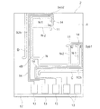
図1において、本実施形態に係る6軸力センサチップ1は、平面形状が好ましくは正方形である半導体基板2を利用して形成されている。正方形の半導体基板2の一辺の長さは例えば5.5mmである。なお基板は半導体基板には限定されない。6軸力センサチップ1の全体形状は、半導体基板2に基づく板状の形状を有している。
In FIG. 1, a six-axis
6軸力センサチップ1は、基板2上に半導体デバイスを形成する場合、好ましくは、一方の表面に半導体製造プロセス技術(フォトリソグラフィ、イオン注入、P−CVD、スパッタリング、RIEなど)を適用して、孔形成配線形成などを施し製作される。
When the semiconductor device is formed on the
以上のごとくして本実施形態に係る6軸力センサチップ1は、半導体センサデバイスとして形成されている。
As described above, the six-axis
6軸力センサチップ1において、6軸力センサとして6軸成分を検出する機能部分は、半導体基板2の一方の表面にイオン注入された活性層(または熱拡散層)より成る例えば8個の歪み抵抗素子(またはピエゾ抵抗素子。以下において「抵抗素子」と記し、歪み抵抗素子を意味するものとする。)Sxa1,Sxa2,Sxb1,Sxb2,Sya1,Sya2,Syb1,Syb2によって形成される。総計8個の抵抗素子は、2個ずつの組(Sxa1,Sxa2),(Sxb1,Sxb2),(Sya1,Sya2),(Syb1,Syb2)で、後述される略T字形状の4つの連結部5A〜5Dの各々における作用部4との境界縁近傍に沿って配置されている。
In the 6-axis
さらに6軸力センサチップ1には、8個の抵抗素子のそれぞれに対応して、個別に、上記と同様な活性層(熱拡散層)より成る温度補償用抵抗素子11が形成されている。温度補償用抵抗素子11は総数で8個形成されている。8個の温度補償用抵抗素子11は、後述される作用部4における4ヶ所の非変形領域部に配置されている。
Further, in the six-axis
図1に明確に示されるように、半導体基板2は、板材の厚み方向に貫通して形成された8つの孔A,B,C,D,K,L,M,Nを有している。6軸力センサチップ1は、8つの孔A,B,C,D,K,L,M,Nにより複数の領域に機能的に分離されている。
As clearly shown in FIG. 1, the
孔A,B,C,D,K,L,M,Nのいずれも相対的に狭い幅を有するスリット状の形状を有している。孔A,B,C,Dはほぼ直線状スリットの形状を有し、孔K,L,M,Nは略L字型のスリット形状を有している。直線形状の貫通孔A,B,C,Dの各々の両端部は、外側に向かって湾曲形状で折り曲げられた形状を有している。略L字型の貫通孔K,L,M,Nの各々の両端部は、内側に向かって湾曲形状で折り曲げられた折曲げ形状部K−1,L−1,M−1,N−1を有している。さらに略L字型の貫通孔K,L,M,Nの各々では、両端部の折曲げ形状部K−1,L−1,M−1,N−1のそれぞれに対して、同じ形状でかつ折曲げ形状が同じ向きとなるようなスリット状孔部K−2,L−2,M−2,N−2が形成されている。孔部K−2,L−2,M−2,N−2のそれぞれは、対応する折曲げ形状部K−1,L−1,M−1,N−1に対して、略平行であり、かつ所定の一定距離の位置関係にある。 Each of the holes A, B, C, D, K, L, M, and N has a slit-like shape having a relatively narrow width. The holes A, B, C, and D have a substantially straight slit shape, and the holes K, L, M, and N have a substantially L-shaped slit shape. Both end portions of each of the straight through holes A, B, C, and D have a shape bent in a curved shape toward the outside. Both end portions of the substantially L-shaped through holes K, L, M, and N are bent shape portions K-1, L-1, M-1, and N-1 that are bent inwardly. have. Further, each of the substantially L-shaped through holes K, L, M, and N has the same shape as the bent shape portions K-1, L-1, M-1, and N-1 at both ends. In addition, slit-shaped holes K-2, L-2, M-2, and N-2 are formed so that the bent shapes are in the same direction. Each of the hole portions K-2, L-2, M-2, and N-2 is substantially parallel to the corresponding bent shape portions K-1, L-1, M-1, and N-1. And a predetermined fixed distance.
上記のごとく8つの貫通孔A,B,C,D,K,L,M,Nを形成することによって、6軸力センサチップ1を形成する半導体基板2は、中央部に位置する正方形に類似する平面形状を有した作用部4と、この作用部4を囲むような位置にあるほぼ正方形リング形状の支持部3と、作用部4と支持部3の間に位置して四辺の各部分に対応して両者を連結する略T字形状の4つの連結部5A,5B,5C,5Dとから構成される。
By forming the eight through holes A, B, C, D, K, L, M, and N as described above, the
作用部4は、半導体基板2に孔K,L,M,Nを形成することによって形成される。また略T字形状の4つの連結部5A,5B,5C,5Dは、半導体基板2に孔A,B,C,D,K,L,M,Nを形成することにより、孔A,B,C,Dと孔K,L,M,Nとの間に形成される。
The
4つの連結部5A〜5Dは、それぞれ、ほぼT字梁となっており、橋梁部5Aaおよび弾性部5Ab、橋梁部5Baおよび弾性部5Bb、橋梁部5Caおよび弾性部5Cb、橋梁部5Daおよび弾性部5Dbを備える。連結部5A〜5Dの各々の橋梁部(5Aa,5Ba,5Ca,Da)は、前述した孔K,L,M,Nの両端部の折曲げ形状部K−1,L−1,M−1,N−1によって、その間の部分として形成されている。
Each of the four connecting
上記の形状および構造を有する半導体基板2に関して、周囲の支持部3は、例えば6軸力センサのユニットに組み付けられるとき、下面から支持台座で支持される部分である。また作用部4は、外部から連結ロッド等を介して外力や荷重等(以下「外力」と記す)が伝達されるとき、当該外力の作用を直接に受ける部分である。作用部4は、通常、その中央部で外力を受けるように構成される。また連結部5A,5B,5C,5Dは、作用部4が外力を受けて変形や位置の変化を生じたとき、これに連動して変形や位置変化を顕著に生じ、固定部、作用部、連結部等の中で最も応力が生じる部分(起歪部)である。
With respect to the
上記の歪み抵抗素子は、起歪部である連結部5A,5B,5C,5Dの表面部に形成される。なお連結部(5A,5B,5C,5D)の上において歪み抵抗素子が配置される場所は、必ずしも連結部で最も応力が生じる場所とは限らない。歪み抵抗素子は、その形成プロセスや配線ルート等、他の様々な要件をも考慮して、最適位置に配置される。
The strain resistance element is formed on the surface portions of the connecting
また上記の作用部4は、外力が印加または入力される中央部(外力作用領域部)4Aと、中央部4Aの周囲に位置する4隅に相当する4つの角部4Bとから形成される。破線で示した円4Cは、外力等を伝達する連結ロッドが接続される連結領域である。円4Cの直径は例えば1.6mmである。作用部4における4つの角部4Bの外縁部は、孔K,L,N,Mによって自由端として形成されている。従って4つの角部4Bの自由端近傍の領域は、中央部4Aに外力が加わったときでも、その部分自体に変形を生じない非変形領域部となっている。非変形領域部である4つの角部4Bの各々には、前述した通り、孔K,L,N,Mに付加されたスリット状孔部K−2,L−2,M−2,N−2が形成されている。
Moreover, said
作用部4では、その中央部4Aに外力が印加され、その周囲の4つのT字梁の連結部5A〜5Dは、それぞれ、橋梁部5Aaおよび弾性部5Ab、橋梁部5Baおよび弾性部5Bb、橋梁部5Caおよび弾性部5Cb、橋梁部5Daおよび弾性部5Dbを備えている。連結部5A〜5Dの弾性部5Ab,5Bb,5Cb,5Dbは、それぞれ、孔A,B,C,Dの内側領域において、支持部3に対して、その長手方向における両端部で接続されている。連結部5A〜5Dの橋梁部5Aa,5Ba,5Ca,5Daは、それぞれ、長手方向における一方の端部(内側端部)が、作用部4の一辺に相当する部分に接続され、また、他方の端部(外側端部)が対応する弾性部に接続されている。橋梁部と弾性部からなる連結部、連結部と作用部との間の接続部分、連結部と支持部との間の接続部分は、半導体基板2として一体的に形成されている。
In the
橋梁部5Aa,5Ba,5Ca,5Daと、弾性部5Ab,5Bb,5Cb,5Dbおよび作用部4との各接続部は、作用部4に印加される外力による応力を分散させ、印加される外力に対する強度を持たせるため、円弧状に加工、好ましくはR加工されている。
Each connecting part of the bridge parts 5Aa, 5Ba, 5Ca, 5Da, the elastic parts 5Ab, 5Bb, 5Cb, 5Db and the
図1において、例えば抵抗素子Sya1,Sya2は、連結部5Aにおいて、作用部4と橋梁部5Aaとの接続部近傍に形成されている。すなわち連結部5Aの表面において、作用部4に印加される外力に対応して応力が生じ、それにより歪みが最も顕著に発生する部分(起歪部)に配置するように形成されている。さらに抵抗素子Sya1,Sya2は、橋梁部5Aaの幅方向に並び、かつそれらの長手方向が橋梁部5Aaの長軸方向に対して平行となるように形成されている。また孔Lの端部L−1の孔縁と抵抗素子Sya1との間の距離と、孔Kの端部K−1の孔縁と抵抗素子Syb2との間の距離とは等しくなるように設定されている。
In FIG. 1, for example, resistance elements Sya1 and Sya2 are formed in the vicinity of the connecting portion between the
また抵抗素子Sya1に対応する温度補償用抵抗素子11は、孔Lの端部L−1に対応する孔部L−2の近傍の所定位置に形成される。端部L−1に対する抵抗素子Sya1の配置箇所周辺の構造と、孔部L−2に対する温度補償用抵抗素子11の配置箇所周辺の構造とは同じである。すなわち、抵抗素子Sya1の配置箇所周辺構造と、対応する温度補償用抵抗素子11の配置箇所周辺構造とは同じである。
The temperature compensating
同様に、抵抗素子Sya2に対応する温度補償用抵抗素子11は、孔Kの端部K−1に対応する孔部K−2の近傍の所定位置に形成される。端部K−1に対する抵抗素子Sya2の配置箇所周辺構造と、孔部K−2に対する温度補償用抵抗素子11の配置箇所周辺構造とは同じである。すなわち、抵抗素子Sya2の配置箇所周辺構造と、対応する温度補償用抵抗素子11の配置箇所周辺構造とは同じである。
Similarly, the temperature compensating
他の抵抗素子Syb1,Syb2、抵抗素子Sxa1,Sxa2、抵抗素子Sxb1,Sxb2についても、上述した抵抗素子Sya1,Sya2と同様に、それぞれ、作用部4および橋梁部5Caの接続部近傍、作用部4および橋梁部5Baの接続部近傍、作用部4および橋梁部5Daの接続部近傍に配置するよう形成されている。さらに、抵抗素子Syb1,Syb2,Sxa1,Sxa2,Sxb1,Sxb2の配置箇所周辺構造と、各抵抗素子に対応する温度補償用抵抗素子11の配置箇所周辺構造とが同じである点についても、それぞれが対応する折曲げ形状部K−1,L−1,M−1,N−1および孔部K−2,L−2,M−2,N−2について成り立つ。
The other resistance elements Syb1 and Syb2, the resistance elements Sxa1 and Sxa2, and the resistance elements Sxb1 and Sxb2 are similar to the above-described resistance elements Sya1 and Sya2, respectively, in the vicinity of the connection part of the
半導体基板2の周縁には、各辺に沿って所要の幅にてほぼ正方形リング状のGND(接地(GROUND))配線12が形成されている。GND配線12には所要数のGND電極パッドが接続されている。
A substantially square ring-shaped GND (GROUND)
半導体基板2では、さらに、各辺のそれぞれに沿って10個の信号電極パッド13が形成されている。また複数の斜線部分14は電気配線の配線パターンの配線領域のイメージを示している。配線パターン14は、実際上、所要本数の配線で形成されている。
In the
上記配線パターン14の一部の具体的な配線例を図4に示す。図4では、孔Nの周辺部における角部4Bでの抵抗素子Syb1,Sxb2およびそれぞれに対応する温度補償用抵抗素子11に関する配線パターン14の具体的な配線構造を示している。図4において、図1で示した要素と同一の要素には同一の符号を付している。
A specific wiring example of a part of the
上記のような孔構造、この孔構造に基づいて形成される作用部や連結部等、歪み抵抗素子、温度補償用抵抗素子、複数の電極、配線パターン等が作りられた半導体基板2において、符号15で示すごときX軸、Y軸、Z軸から成る3軸直交座標系が定義されている。
In the
図2を参照して1つの歪み抵抗素子(例えばSyb1)と1つの温度補償用抵抗素子11との配置関係、それぞれの配置箇所周辺構造、配線パターン14について説明する。
With reference to FIG. 2, the arrangement relationship between one strain resistance element (for example, Syb1) and one temperature compensating
図2は、図1における孔Nの端部N−1および孔部N−2と、これらの近傍に配置される抵抗素子Syb1およびこれに対応する温度補償用抵抗素子11の部分を拡大して示した半導体基板2の要部拡大平面図である。
FIG. 2 is an enlarged view of the end N-1 and the hole N-2 of the hole N in FIG. 1, the resistance element Syb1 arranged in the vicinity thereof, and the temperature
図2では、孔Nにおける抵抗素子Syb1側の一方の端部の折曲げ形状部N−1と、この折曲げ形状部N−1の近傍に形成された孔部N−2が示される。折曲げ形状部N−1と孔部N−2は同寸法および同形状であり、さらにその折曲げ形状に関して同じ向きを向くように形成されている。折曲げ形状部N−1に対する抵抗素子Syb1の配置箇所と、孔部N−1に対する温度補償用抵抗素子11の配置箇所は同じである。すなわち、折曲げ形状部N−1に対する抵抗素子Syb1の位置および孔縁からの距離(d1)と、孔部N−1に対する温度補償用抵抗素子11の位置および孔縁からの距離(d1)とはそれぞれ等しい。また、連結部5の橋梁部5Caに配置された抵抗素子Syb1と、作用部4の角部4Bに配置された温度補償用抵抗素子11との間の距離は可能限り小さくなるように設計される。よって、抵抗素子Syb1の配置箇所周辺構造と、温度補償用抵抗素子11の配置箇所周辺構造とは同じとなる。その結果、抵抗素子Syb1と温度補償用抵抗素子11の各々の温度条件、伝熱条件、または熱による基板の微小変形に起因する歪みの影響等の温度特性が等しくなる。ここで、「温度条件が等しい」とは温度環境が同じであり、同等の熱影響を受けることをいい、また「伝熱条件が等しい」とは熱の伝わり方に基づく温度の変化が同じであり、同等の伝熱量特性を有することをいう。
FIG. 2 shows a bent shape portion N-1 at one end of the hole N on the resistance element Syb1 side, and a hole portion N-2 formed in the vicinity of the bent shape portion N-1. The bent shape portion N-1 and the hole portion N-2 have the same dimensions and the same shape, and are formed to face the same direction with respect to the bent shape. The location where the resistance element Syb1 is disposed with respect to the bent shape portion N-1 is the same as the location where the temperature compensating
本実施形態の形状および構造によれば、孔Nの折曲げ形状部N−1と孔部N−2とが同形および同寸法であるために、これらの孔を流れる気体による伝熱条件(放熱性など)が等しくなる。 According to the shape and structure of the present embodiment, since the bent shape portion N-1 and the hole portion N-2 of the hole N have the same shape and the same size, heat transfer conditions (heat radiation) by the gas flowing through these holes Sex, etc.) are equal.
図2を参照して説明した抵抗素子Syb1、これに対応する温度補償用抵抗素子11、折曲げ形状部N−1、孔部N−2によって形成される構造は、他の7つの抵抗素子Sxa1,Sxa2,Sxb1,Sxb2,Sya1,Sya2,Syb2のそれぞれについても同様に適用される。
The structure formed by the resistance element Syb1 described with reference to FIG. 2, the temperature
次に、図3を参照して、抵抗素子Syb1と温度補償用抵抗素子11との間の配線パターン14による電気的な接続関係を説明する。
Next, with reference to FIG. 3, the electrical connection relationship by the
温度補償用抵抗素子11と抵抗素子Syb1はブリッジ回路の半回路(ハーフブリッジ)を成す結線構造で構成されている。抵抗素子Syb1と温度補償用抵抗素子11との間の接続点は信号配線21を経由してGND配線12に接続される。また抵抗素子Syb1の他端は信号配線22で信号電極パッド13に接続され、温度補償用抵抗素子11の他端は信号配線23を介して信号電極パッド13に接続されている。
The temperature compensating
図2および図3に示した電気配線の構造によれば、温度補償用抵抗素子11の信号配線23の方が抵抗素子Syb1の信号配線22に比較して必然的に長くなる。信号配線23と信号配線22の長さの差異に起因する初期抵抗値のずれは、配線長さ比、幅比、厚さ比等などを適宜に変えることにより、調整することができる。これにより、歪み抵抗素子および温度補償用抵抗素子の初期抵抗値を均一にすることができる。
2 and 3, the
上記の配線抵抗値の調整の一例を図5に示す。図5では、孔Nの周辺部における角部4Bでの抵抗素子Syb1,Sxb2およびそれぞれに対応する温度補償用抵抗素子11に関する配線パターン14での抵抗値を調整するための具体的な配線構造を示している。図5において、図1で示した要素と同一の要素には同一の符号を付している。この配線構造では、配線パターン14において、配線長さによって抵抗値を適宜に調整する部分31,32,33,34,35,36を設け、歪み抵抗素子に関する配線の抵抗値と、温度補償用抵抗素子に関する配線の抵抗値とを同一にするように調整を行っている。なお、図5において符号37で指摘された部分は抵抗減調整用の配線パターン部分である。
An example of the adjustment of the wiring resistance value is shown in FIG. In FIG. 5, a specific wiring structure for adjusting the resistance value in the
抵抗素子Syb1と温度補償用抵抗素子11に関する図3に示した上記結線構造は、他の7つの抵抗素子Sxa1,Sxa2,Sxb1,Sxb2,Sya1,Sya2,Syb2のそれぞれについても適用される。
The connection structure shown in FIG. 3 relating to the resistance element Syb1 and the temperature compensating
6軸力センサチップ1は、歪み抵抗素子とこれに対応する温度補償用抵抗素子の配置箇所周辺構造を同じとしたので、歪み抵抗素子とこれに対応する温度補償用抵抗素子との間で初期抵抗値の差異を低減でき、初期抵抗値のバラツキによる各チップ間の差異を低減して再現性を向上することができ、精度の高い温度補償を行って高精度の応力検出性能を実現することができる。
Since the six-axis
次に、図6に本発明の他の実施形態を示す。図6は図2と同様な図であり、図6において図2で説明した要素と実質的に同一の要素には同一の符号を付し、その説明を省略する。本実施形態に係る6軸力センサチップ1では、孔Nの端部の折曲げ形状部N−1に対して、前述の孔部N−2の代わりに孔部N−3が形成される。孔部N−3は、その形状および寸法は折曲げ形状部N−1の形状および寸法と同じであり、かつ向きが反対となっている。また同時に、孔部N−3は、その形状および寸法は、右隣の孔Mの折曲げ形状部M−1の形状および寸法と同じであり、かつ向きが同じとなっている。
Next, FIG. 6 shows another embodiment of the present invention. FIG. 6 is a diagram similar to FIG. 2. In FIG. 6, elements that are substantially the same as those described in FIG. 2 are given the same reference numerals, and descriptions thereof are omitted. In the six-axis
図6に示されるごとく、抵抗素子Syb1は孔Mの折曲げ形状部M−1に接近させて配置され、温度補償用抵抗素子11は孔部N−3に接近して配置されている。この場合において、抵抗素子Syb1の配置箇所周辺構造と、温度補償用抵抗素子11の配置箇所周辺構造とはまったく同じである。
As shown in FIG. 6, the resistance element Syb1 is arranged close to the bent shape part M-1 of the hole M, and the temperature compensating
抵抗素子Syb1と温度補償用抵抗素子11の各配置箇所周辺構造を上記のごとく形成することにより、抵抗素子Syb1と温度補償用抵抗素子11における温度条件および伝熱条件を同じすることができ、前述した実施形態と同等の効果を達成することができる。
By forming the peripheral structure of each location of the resistive element Syb1 and the temperature compensating
次に、6軸力センサチップ1の各軸の出力バランスを良好するという観点からの本発明の他の実施形態を説明する。
Next, another embodiment of the present invention from the viewpoint of improving the output balance of each axis of the six-axis
前述した通り6軸力センサチップ1のベース部材は半導体基板12である。半導体基板12は、結晶方位を有しているので、これを考慮せずに、例えばX軸方向に作られる歪み抵抗素子や温度補償用抵抗素子をY軸方向に作られる歪み抵抗素子等と同形のものとすると、X軸方向の歪み抵抗素子等の初期抵抗値とY軸方向の歪み抵抗素子等の初期抵抗値との間で差異が生じる。そこで、それぞれ平面形状が長方形で膜状に形成されるX軸方向の歪み抵抗素子等とY軸方向の歪み抵抗素子等の少なくともいずれか一方について、半導体基板の結晶方位を考慮して、長手方向の長さ寸法、幅寸法、深さ(厚さ)寸法、イオン注入された注入要素(キャリア)の濃度等の少なくともいずれか1つの要素を適宜に変化させ、それらの抵抗値を積極的に異ならせることで、歪み抵抗素子等の初期抵抗値に最適にする。これによって、各軸の出力バランスを良好にすることができ、高精度な応力検出を行うことができる。
As described above, the base member of the six-axis
例えば、X軸方向(基板の抵抗値の高い軸)に平行に配置される歪み抵抗素子の長さをY軸(基板の抵抗値の低い軸)に比べて短くすると、X軸方向とY軸方向に配置される歪み抵抗値の初期抵抗値を均一化することができる。例えば、X軸のものをY軸のものに比べて1%短くすると、素子の抵抗値をY軸のものと1%差異をつけることができ、基板の結晶方位に起因するXY軸間の初期抵抗値の差異を調整することができる。これにより、X軸方向の歪み抵抗素子の抵抗値とY軸方向の歪み抵抗素子の抵抗値を調整して、出力バランスを最適にすることができる。 For example, if the length of a strain resistance element arranged in parallel to the X-axis direction (axis with a high resistance value of the substrate) is shorter than the Y-axis (axis with a low resistance value of the substrate), the X-axis direction and the Y-axis The initial resistance value of the strain resistance value arranged in the direction can be made uniform. For example, if the X-axis is 1% shorter than the Y-axis, the resistance value of the element can be different from that of the Y-axis by 1%. The difference in resistance value can be adjusted. Thereby, the output balance can be optimized by adjusting the resistance value of the strain resistance element in the X-axis direction and the resistance value of the strain resistance element in the Y-axis direction.
以上の実施形態で説明された構成、形状、大きさおよび配置関係については本発明が理解・実施できる程度に概略的に示したものにすぎず、また数値および各構成の組成(材質)については例示にすぎない。従って本発明は、説明された実施形態に限定されるものではなく、特許請求の範囲に示される技術的思想の範囲を逸脱しない限り様々な形態に変更することができる。 The configurations, shapes, sizes, and arrangement relationships described in the above embodiments are merely shown to the extent that the present invention can be understood and implemented, and the numerical values and the compositions (materials) of the respective configurations are as follows. It is only an example. Therefore, the present invention is not limited to the described embodiments, and can be variously modified without departing from the scope of the technical idea shown in the claims.
本発明は、外力等が加わった時に高い精度で温度補償が行われ高精度の応力検出を行える6軸力センサチップ等を製作し、高い精度での応力検出に利用される。 The present invention produces a six-axis force sensor chip that can perform temperature compensation with high accuracy when external force is applied and can detect stress with high accuracy, and is used for stress detection with high accuracy.
1 6軸力センサチップ
2 半導体基板
3 支持部
4 作用部
4A 中央部(外力作用領域部)
4B 角部(非変形領域部)
11 温度補償用抵抗素子
14 配線パターン
A〜D 孔
K〜N 孔
Sxa1,Sxa2 歪み抵抗素子
Sya1,Sya2 歪み抵抗素子
Sxb1,Sxb2 歪み抵抗素子
Syb1,Syb2 歪み抵抗素子
DESCRIPTION OF
4B Corner (non-deformation area)
DESCRIPTION OF
Claims (7)
前記作用部が外力を受け変形が生じたときに連動して変形する起歪部であって前記連結部に設けられる歪み抵抗素子と、
前記非変形領域部に設けられる温度補償用抵抗素子とを備え、
前記歪み抵抗素子と前記温度補償用抵抗素子は、
前記作用部の中心を基準に点対称の位置関係にあって、かつ、前記中心から実質的に同一の距離に設けられており、
前記ベース部材は、
複数のスリット状の孔により、前記作用部、前記支持部、及び前記連結部とからなる複数の領域に機能的に分離されており、中央部に前記作用部の前記外力作用領域部を、前記外力作用領域部の周囲の領域に前記作用部の非変形領域部を備え、
前記孔のいくつかは、その両端部が内側に向かって湾曲状に折り曲げられた折り曲げ形状部と、この折り曲げ形状部と同じ形状のスリット状孔部とを有し、
前記起歪部に設けられた前記歪み抵抗素子の配列箇所近傍の所定位置に前記折り曲げ形状部が形成され、
前記非変形領域部に設けられた温度補償用抵抗素子の配列箇所近傍の所定位置に前記スリット状孔部が形成され、前記非変形領域部は、前記連結部と前記作用部との間を前記スリット状孔部により分離することで前記作用部の外縁部に自由端として形成され、
前記ベース部材が備える前記作用部と前記支持部と前記連結部は前記ベース部材に複数の所定の孔を形成することにより作られ、前記歪み抵抗素子の周辺に形成される前記孔と同じ形状で同じ向きの孔が前記温度補償用抵抗素子の周辺に形成されている配置箇所周辺構造を有することを特徴とする力覚センサ用チップ。 An external force acting region part to which an external force is applied or an external force is input, an action part having a non-deformation region part that does not deform in itself even if an external force is applied or an external force is input, and the action part is supported A base member provided with a support part and a connecting part that is located between the action part and the support part and connects the two;
A strain-resisting element that is deformed in conjunction with deformation when the acting part receives external force and undergoes deformation;
A temperature compensation resistance element provided in the non-deformation region,
The strain resistance element and the temperature compensating resistance element are:
It is in a point-symmetric positional relationship with respect to the center of the action part, and is provided at substantially the same distance from the center.
The base member is
A plurality of slit-shaped holes are functionally separated into a plurality of regions composed of the action portion, the support portion, and the connection portion, and the external force action region portion of the action portion is disposed in the center portion. A non-deformation region portion of the action portion is provided in a region around the external force action region portion,
Some of the holes have a bent shape portion whose both end portions are bent inwardly, and a slit-like hole portion having the same shape as the bent shape portion,
The bent shape portion is formed at a predetermined position in the vicinity of the arrangement location of the strain resistance elements provided in the strain generating portion,
The slit-shaped hole is formed at a predetermined position in the vicinity of the arrangement portion of the temperature compensating resistance elements provided in the non-deformation region, and the non-deformation region is formed between the connection portion and the action portion. Formed as a free end on the outer edge of the working part by separating with a slit-shaped hole,
The action part, the support part, and the connection part included in the base member are formed by forming a plurality of predetermined holes in the base member, and have the same shape as the holes formed around the strain resistance element. A force sensor chip having an arrangement location peripheral structure in which holes in the same direction are formed in the periphery of the temperature compensating resistance element.
前記作用部が外力を受け変形が生じたときに連動して変形する起歪部であって前記連結部に設けられる歪み抵抗素子と、
前記非変形領域部に設けられる温度補償用抵抗素子とを備え、
前記歪み抵抗素子と前記温度補償用抵抗素子は、
前記作用部の中心を基準に点対称の位置関係にあって、かつ、前記中心から実質的に同一の距離に設けられており、
前記ベース部材は、
複数のスリット状の孔により、前記作用部、前記支持部、及び前記連結部とからなる複数の領域に機能的に分離されており、中央部に前記作用部の前記外力作用領域部を、前記外力作用領域部の周囲の領域に前記作用部の非変形領域部を備え、
前記孔のいくつかは、その両端部が内側に向かって湾曲状に折り曲げられた折り曲げ形状部と、この折り曲げ形状部と同じ形状のスリット状孔部とを有し、
前記起歪部に設けられた前記歪み抵抗素子の配列箇所近傍の所定位置に前記折り曲げ形状部が形成され、
前記非変形領域部に設けられた温度補償用抵抗素子の配列箇所近傍の所定位置に前記スリット状孔部が形成され、前記非変形領域部は、前記連結部と前記作用部との間を前記スリット状孔部により分離することで前記作用部の外縁部に自由端として形成され、
前記ベース部材が備える前記作用部と前記支持部と前記連結部は前記ベース部材に複数の所定の孔を形成することにより作られ、前記歪み抵抗素子の周辺に形成される前記孔と同じ形状で反対向きの孔が前記温度補償用抵抗素子の周辺に形成されていることを特徴とする力覚センサ用チップ。 An external force acting region part to which an external force is applied or an external force is input, an action part having a non-deformation region part that does not deform in itself even if an external force is applied or an external force is input, and the action part is supported A base member provided with a support part and a connecting part that is located between the action part and the support part and connects the two;
A strain-resisting element that is deformed in conjunction with deformation when the acting part receives external force and undergoes deformation;
A temperature compensation resistance element provided in the non-deformation region,
The strain resistance element and the temperature compensating resistance element are:
It is in a point-symmetric positional relationship with respect to the center of the action part, and is provided at substantially the same distance from the center.
The base member is
A plurality of slit-shaped holes are functionally separated into a plurality of regions composed of the action portion, the support portion, and the connection portion, and the external force action region portion of the action portion is disposed in the center portion. A non-deformation region portion of the action portion is provided in a region around the external force action region portion,
Some of the holes have a bent shape portion whose both end portions are bent inwardly, and a slit-like hole portion having the same shape as the bent shape portion,
The bent shape portion is formed at a predetermined position in the vicinity of the arrangement location of the strain resistance elements provided in the strain generating portion,
The slit-shaped hole is formed at a predetermined position in the vicinity of the arrangement portion of the temperature compensating resistance elements provided in the non-deformation region, and the non-deformation region is formed between the connection portion and the action portion. Formed as a free end on the outer edge of the working part by separating with a slit-shaped hole,
The action part, the support part, and the connection part included in the base member are formed by forming a plurality of predetermined holes in the base member, and have the same shape as the holes formed around the strain resistance element. A force sensor chip, wherein a hole in the opposite direction is formed around the temperature compensating resistor element.
前記ベース部材の上に形成される複数の前記歪み抵抗素子の各々の初期抵抗値は、前記ベース部材の表面上で定められた直交2軸のそれぞれに応じて、前記結晶方位に配慮して異なる値としたことを特徴とする請求項1〜5のいずれか1項記載の力覚センサ用チップ。 The base member is formed of a semiconductor substrate having a crystal orientation,
The initial resistance value of each of the plurality of strain resistance elements formed on the base member is different in consideration of the crystal orientation according to each of the two orthogonal axes defined on the surface of the base member. The force sensor chip according to claim 1, wherein the force sensor chip is a value.
Priority Applications (2)
| Application Number | Priority Date | Filing Date | Title |
|---|---|---|---|
| JP2006334679A JP5174343B2 (en) | 2006-12-12 | 2006-12-12 | Force sensor chip |
| US12/000,405 US7707899B2 (en) | 2006-12-12 | 2007-12-12 | Force sensor chip |
Applications Claiming Priority (1)
| Application Number | Priority Date | Filing Date | Title |
|---|---|---|---|
| JP2006334679A JP5174343B2 (en) | 2006-12-12 | 2006-12-12 | Force sensor chip |
Publications (3)
| Publication Number | Publication Date |
|---|---|
| JP2008145342A JP2008145342A (en) | 2008-06-26 |
| JP2008145342A5 JP2008145342A5 (en) | 2009-12-17 |
| JP5174343B2 true JP5174343B2 (en) | 2013-04-03 |
Family
ID=39582077
Family Applications (1)
| Application Number | Title | Priority Date | Filing Date |
|---|---|---|---|
| JP2006334679A Expired - Fee Related JP5174343B2 (en) | 2006-12-12 | 2006-12-12 | Force sensor chip |
Country Status (2)
| Country | Link |
|---|---|
| US (1) | US7707899B2 (en) |
| JP (1) | JP5174343B2 (en) |
Families Citing this family (12)
| Publication number | Priority date | Publication date | Assignee | Title |
|---|---|---|---|---|
| JP5243704B2 (en) * | 2006-08-24 | 2013-07-24 | 本田技研工業株式会社 | Force sensor |
| JP5243988B2 (en) * | 2009-02-10 | 2013-07-24 | 本田技研工業株式会社 | Multi-axis force sensor and acceleration sensor |
| US8745571B2 (en) | 2011-02-14 | 2014-06-03 | International Business Machines Corporation | Analysis of compensated layout shapes |
| US9003897B2 (en) | 2012-05-10 | 2015-04-14 | Honeywell International Inc. | Temperature compensated force sensor |
| US9581511B2 (en) * | 2013-10-15 | 2017-02-28 | Meggitt (Orange County), Inc. | Microelectromechanical pressure sensors |
| US10203254B2 (en) * | 2016-09-12 | 2019-02-12 | Apple Inc. | Strain sensor with thermally conductive element |
| JP6760575B2 (en) * | 2016-10-07 | 2020-09-23 | ミネベアミツミ株式会社 | Sensor chip, strain generator, force sensor device |
| JP7025981B2 (en) * | 2018-04-12 | 2022-02-25 | 株式会社小野測器 | Torque measuring device |
| JP2021071305A (en) * | 2019-10-29 | 2021-05-06 | ミネベアミツミ株式会社 | Force sensor device |
| JP2022142118A (en) * | 2021-03-16 | 2022-09-30 | ミネベアミツミ株式会社 | Sensor chip and force sensor device |
| JP2022142117A (en) * | 2021-03-16 | 2022-09-30 | ミネベアミツミ株式会社 | Sensor chip, and force sensor device |
| JP2022142116A (en) * | 2021-03-16 | 2022-09-30 | ミネベアミツミ株式会社 | Strain body and force sensor device |
Family Cites Families (26)
| Publication number | Priority date | Publication date | Assignee | Title |
|---|---|---|---|---|
| US3985025A (en) * | 1975-01-20 | 1976-10-12 | Ormond Alfred N | Shear measuring flexure isolated load cells |
| JPS5814751B2 (en) * | 1977-03-17 | 1983-03-22 | 株式会社日立製作所 | Diaphragm strain gauge |
| US4221134A (en) * | 1979-08-20 | 1980-09-09 | Ekstrom Jr Regner A | Differential pressure transducer with strain gauge |
| JPS5660066A (en) * | 1979-10-19 | 1981-05-23 | Nec Corp | Semiconductor strain detector |
| JPS5780532A (en) * | 1980-11-07 | 1982-05-20 | Hitachi Ltd | Semiconductor load converter |
| JPS57169643A (en) * | 1981-04-13 | 1982-10-19 | Yamato Scale Co Ltd | Load cell for multiple components of force |
| US5207554A (en) * | 1982-09-21 | 1993-05-04 | Fujitsu Limited | Supporting device |
| CA1237739A (en) * | 1982-09-21 | 1988-06-07 | Kazuo Asakawa | Supporting device |
| JPS62213280A (en) * | 1986-03-14 | 1987-09-19 | Nissan Motor Co Ltd | Semiconductor acceleration sensor |
| JPH0617834B2 (en) * | 1987-04-24 | 1994-03-09 | 株式会社エンプラス研究所 | Force detector |
| US4905523A (en) * | 1987-04-24 | 1990-03-06 | Wacoh Corporation | Force detector and moment detector using resistance element |
| US5095762A (en) * | 1988-07-14 | 1992-03-17 | University Of Hawaii | Multidimensional force sensor |
| JP2560140B2 (en) * | 1990-08-03 | 1996-12-04 | 日産自動車株式会社 | Semiconductor device |
| US6314823B1 (en) * | 1991-09-20 | 2001-11-13 | Kazuhiro Okada | Force detector and acceleration detector and method of manufacturing the same |
| JP2548347Y2 (en) * | 1991-12-03 | 1997-09-17 | 大和製衡株式会社 | Load cell |
| JPH05215627A (en) * | 1992-02-04 | 1993-08-24 | Kazuhiro Okada | Device for detecting force, acceleration, and magnetism in multidimensional direction |
| JP4141574B2 (en) | 1999-03-19 | 2008-08-27 | エランテック デバイシーズ コーポレイション | Thick film circuit board for pointing stick |
| JP3870895B2 (en) * | 2002-01-10 | 2007-01-24 | 株式会社村田製作所 | Angular velocity sensor |
| US6823744B2 (en) * | 2002-01-11 | 2004-11-30 | Honda Giken Kogyo Kabushiki Kaisha | Six-axis force sensor |
| US7021154B2 (en) * | 2002-09-24 | 2006-04-04 | Kabushiki Kaisha Toyota Chuo Kenkyusho | Force sensing element |
| JP4045979B2 (en) * | 2003-02-26 | 2008-02-13 | 株式会社デンソー | Pressure detection device |
| JP4192084B2 (en) * | 2003-06-17 | 2008-12-03 | ニッタ株式会社 | Multi-axis sensor |
| JP2005106679A (en) * | 2003-09-30 | 2005-04-21 | Nitta Ind Corp | Multiaxial sensor unit and multiaxial sensor using the same |
| JP4680566B2 (en) * | 2004-10-26 | 2011-05-11 | 本田技研工業株式会社 | Multi-axis force sensor chip and multi-axis force sensor using the same |
| US6988412B1 (en) * | 2004-11-30 | 2006-01-24 | Endevco Corporation | Piezoresistive strain concentrator |
| JP2006242797A (en) * | 2005-03-04 | 2006-09-14 | Matsushita Electric Ind Co Ltd | Distortion sensor and its manufacturing method |
-
2006
- 2006-12-12 JP JP2006334679A patent/JP5174343B2/en not_active Expired - Fee Related
-
2007
- 2007-12-12 US US12/000,405 patent/US7707899B2/en active Active
Also Published As
| Publication number | Publication date |
|---|---|
| JP2008145342A (en) | 2008-06-26 |
| US7707899B2 (en) | 2010-05-04 |
| US20080156112A1 (en) | 2008-07-03 |
Similar Documents
| Publication | Publication Date | Title |
|---|---|---|
| JP5174343B2 (en) | Force sensor chip | |
| JP5007083B2 (en) | Force sensor chip | |
| JP4958501B2 (en) | Force sensor chip and external force transmission mechanism | |
| JP5507306B2 (en) | Force sensor chip and acceleration sensor chip | |
| JP5303101B2 (en) | Force sensor chip | |
| JP4680566B2 (en) | Multi-axis force sensor chip and multi-axis force sensor using the same | |
| US7500406B2 (en) | Multiaxial sensor | |
| US7360456B2 (en) | Six-axis sensor | |
| US6915709B2 (en) | Force detection device | |
| JP2007010379A (en) | Force sensor | |
| JP6611762B2 (en) | Strain gauge and multi-axis force sensor | |
| WO2019009368A1 (en) | Strain gauge and multiple axis force sensor | |
| JP2022191485A (en) | Multi-axis tactile sensor | |
| JP5046321B2 (en) | 3-axis force sensor | |
| JP2013002942A (en) | Force sensor chip | |
| JP6611761B2 (en) | Strain gauge and multi-axis force sensor | |
| JPH05149811A (en) | Axial force sensor for six components | |
| JP6767559B2 (en) | Strain gauge and multi-axial force sensor | |
| JP2006242675A (en) | Resistance type sensor | |
| JP6836641B2 (en) | Strain gauge and 3-axis force sensor | |
| JP6837113B2 (en) | Strain gauge and multi-axial force sensor | |
| JP2008292509A (en) | Force sensor | |
| JP2006058211A (en) | Strain gauge type sensor | |
| JPH02203229A (en) | Force detecting device | |
| JP2019045207A (en) | Pressure sensor |
Legal Events
| Date | Code | Title | Description |
|---|---|---|---|
| A521 | Request for written amendment filed |
Free format text: JAPANESE INTERMEDIATE CODE: A523 Effective date: 20091104 |
|
| A621 | Written request for application examination |
Free format text: JAPANESE INTERMEDIATE CODE: A621 Effective date: 20091104 |
|
| A977 | Report on retrieval |
Free format text: JAPANESE INTERMEDIATE CODE: A971007 Effective date: 20110826 |
|
| A131 | Notification of reasons for refusal |
Free format text: JAPANESE INTERMEDIATE CODE: A131 Effective date: 20110906 |
|
| A521 | Request for written amendment filed |
Free format text: JAPANESE INTERMEDIATE CODE: A523 Effective date: 20111104 |
|
| RD03 | Notification of appointment of power of attorney |
Free format text: JAPANESE INTERMEDIATE CODE: A7423 Effective date: 20120416 |
|
| A131 | Notification of reasons for refusal |
Free format text: JAPANESE INTERMEDIATE CODE: A131 Effective date: 20120529 |
|
| A521 | Request for written amendment filed |
Free format text: JAPANESE INTERMEDIATE CODE: A523 Effective date: 20120726 |
|
| TRDD | Decision of grant or rejection written | ||
| A01 | Written decision to grant a patent or to grant a registration (utility model) |
Free format text: JAPANESE INTERMEDIATE CODE: A01 Effective date: 20121225 |
|
| A61 | First payment of annual fees (during grant procedure) |
Free format text: JAPANESE INTERMEDIATE CODE: A61 Effective date: 20121228 |
|
| R150 | Certificate of patent or registration of utility model |
Ref document number: 5174343 Country of ref document: JP Free format text: JAPANESE INTERMEDIATE CODE: R150 |
|
| LAPS | Cancellation because of no payment of annual fees |