JP5172103B2 - X-ray computed tomography apparatus, collimator for x-ray computed tomography apparatus, and manufacturing method thereof - Google Patents
X-ray computed tomography apparatus, collimator for x-ray computed tomography apparatus, and manufacturing method thereof Download PDFInfo
- Publication number
- JP5172103B2 JP5172103B2 JP2006113892A JP2006113892A JP5172103B2 JP 5172103 B2 JP5172103 B2 JP 5172103B2 JP 2006113892 A JP2006113892 A JP 2006113892A JP 2006113892 A JP2006113892 A JP 2006113892A JP 5172103 B2 JP5172103 B2 JP 5172103B2
- Authority
- JP
- Japan
- Prior art keywords
- collimator
- ray
- groove
- plate
- computed tomography
- Prior art date
- Legal status (The legal status is an assumption and is not a legal conclusion. Google has not performed a legal analysis and makes no representation as to the accuracy of the status listed.)
- Active
Links
- 238000002591 computed tomography Methods 0.000 title claims description 67
- 238000004519 manufacturing process Methods 0.000 title claims description 50
- 238000001514 detection method Methods 0.000 claims description 60
- 238000000034 method Methods 0.000 claims description 57
- 238000010586 diagram Methods 0.000 description 36
- 238000012986 modification Methods 0.000 description 29
- 230000004048 modification Effects 0.000 description 29
- 239000000853 adhesive Substances 0.000 description 27
- 230000001070 adhesive effect Effects 0.000 description 27
- 238000012545 processing Methods 0.000 description 17
- 239000004918 carbon fiber reinforced polymer Substances 0.000 description 14
- 230000000694 effects Effects 0.000 description 9
- 239000000463 material Substances 0.000 description 9
- 229920005989 resin Polymers 0.000 description 9
- 239000011347 resin Substances 0.000 description 9
- 238000003780 insertion Methods 0.000 description 7
- 230000037431 insertion Effects 0.000 description 7
- 239000003822 epoxy resin Substances 0.000 description 6
- 230000035699 permeability Effects 0.000 description 6
- 229920000647 polyepoxide Polymers 0.000 description 6
- -1 polyethylene terephthalate Polymers 0.000 description 6
- 239000005020 polyethylene terephthalate Substances 0.000 description 6
- 229920000139 polyethylene terephthalate Polymers 0.000 description 6
- 229920000049 Carbon (fiber) Polymers 0.000 description 5
- 239000004917 carbon fiber Substances 0.000 description 5
- 238000012423 maintenance Methods 0.000 description 5
- VNWKTOKETHGBQD-UHFFFAOYSA-N methane Chemical compound C VNWKTOKETHGBQD-UHFFFAOYSA-N 0.000 description 5
- 230000005540 biological transmission Effects 0.000 description 4
- 238000006243 chemical reaction Methods 0.000 description 4
- 238000003384 imaging method Methods 0.000 description 4
- 238000004891 communication Methods 0.000 description 3
- 238000009434 installation Methods 0.000 description 3
- 238000007781 pre-processing Methods 0.000 description 3
- 238000002834 transmittance Methods 0.000 description 3
- 0 C*1C(C)(C)CCC1 Chemical compound C*1C(C)(C)CCC1 0.000 description 2
- 239000000470 constituent Substances 0.000 description 2
- 238000012937 correction Methods 0.000 description 2
- 239000011159 matrix material Substances 0.000 description 2
- 230000002093 peripheral effect Effects 0.000 description 2
- 238000003860 storage Methods 0.000 description 2
- OKTJSMMVPCPJKN-UHFFFAOYSA-N Carbon Chemical compound [C] OKTJSMMVPCPJKN-UHFFFAOYSA-N 0.000 description 1
- ZOKXTWBITQBERF-UHFFFAOYSA-N Molybdenum Chemical compound [Mo] ZOKXTWBITQBERF-UHFFFAOYSA-N 0.000 description 1
- 238000010521 absorption reaction Methods 0.000 description 1
- 230000001133 acceleration Effects 0.000 description 1
- 230000003321 amplification Effects 0.000 description 1
- 238000003491 array Methods 0.000 description 1
- 230000000903 blocking effect Effects 0.000 description 1
- 229910052799 carbon Inorganic materials 0.000 description 1
- 230000002542 deteriorative effect Effects 0.000 description 1
- 238000011161 development Methods 0.000 description 1
- 239000000428 dust Substances 0.000 description 1
- 238000010894 electron beam technology Methods 0.000 description 1
- 239000000835 fiber Substances 0.000 description 1
- 238000010438 heat treatment Methods 0.000 description 1
- 229910052751 metal Inorganic materials 0.000 description 1
- 239000002184 metal Substances 0.000 description 1
- 229910052750 molybdenum Inorganic materials 0.000 description 1
- 239000011733 molybdenum Substances 0.000 description 1
- 238000003199 nucleic acid amplification method Methods 0.000 description 1
- 230000003287 optical effect Effects 0.000 description 1
- 210000000056 organ Anatomy 0.000 description 1
- 238000003825 pressing Methods 0.000 description 1
- 230000035945 sensitivity Effects 0.000 description 1
- 239000007787 solid Substances 0.000 description 1
- WFKWXMTUELFFGS-UHFFFAOYSA-N tungsten Chemical compound [W] WFKWXMTUELFFGS-UHFFFAOYSA-N 0.000 description 1
- 229910052721 tungsten Inorganic materials 0.000 description 1
- 239000010937 tungsten Substances 0.000 description 1
- 230000000007 visual effect Effects 0.000 description 1
- XLYOFNOQVPJJNP-UHFFFAOYSA-N water Substances O XLYOFNOQVPJJNP-UHFFFAOYSA-N 0.000 description 1
Images


Description
本発明は、X線CT(Computer Tomography)装置に用いられるコリメータ、当該コリメータの製造方法、及び当該コリメータを有するX線CT装置に関する。 The present invention relates to a collimator used in an X-ray CT (Computer Tomography) apparatus, a method for manufacturing the collimator, and an X-ray CT apparatus having the collimator.
周知の通り、X線CT装置は、X線が被検体内で受けた吸収量に基づいて臓器等の組織のX線吸収率を水のそれを基準としたCT値という指標として計算(再構成)することによって画像(断層像)を得るものである。 As is well known, the X-ray CT apparatus calculates (reconstructs) the X-ray absorption rate of a tissue such as an organ as an index of CT value based on that of water based on the amount of X-rays received in the subject. ) To obtain an image (tomographic image).
このX線CT装置においては、各X線検出素子に入射するX線の形状を整形すると共に散乱X線を除去するために、例えばX線検出器のX線入射側においてコリメータが設けられる。従来の一体型構造を持つコリメータ(以下、「一体型コリメータ」と呼ぶ。)の構成の一例を図35に示す。図35に示すように、一体型コリメータは、被検体体軸に沿ったスライス方向に対して並列配置された円弧形状の上下サポートを有している。また、この上下のサポートにはそれぞれX線焦点(X線源の発光点を想定)を向くようにコリメータ単板を挿入できる上下で対になった溝が形成されており、この溝に、平坦化されたコリメータ単板を挿入して、単板の溝挿入部分を接着剤で硬化することで、コリメータを一体構造として形成する。コリメータ単板は、上下サポートの溝によって支えられると共に、自らの剛性によって単板の反りを劣化させることなく、入射するX線を整形する。 In this X-ray CT apparatus, a collimator is provided, for example, on the X-ray incident side of the X-ray detector in order to shape the shape of the X-ray incident on each X-ray detection element and to remove scattered X-rays. An example of the configuration of a conventional collimator having an integrated structure (hereinafter referred to as “integrated collimator”) is shown in FIG. As shown in FIG. 35, the integrated collimator has arcuate upper and lower supports arranged in parallel in the slice direction along the subject body axis. The upper and lower supports have a pair of upper and lower grooves into which a collimator single plate can be inserted so as to face the X-ray focal point (assuming the emission point of the X-ray source). The collimator single plate is inserted and the groove insertion portion of the single plate is hardened with an adhesive, thereby forming the collimator as an integral structure. The collimator single plate is supported by the grooves of the upper and lower supports, and shapes incident X-rays without deteriorating the warpage of the single plate due to its own rigidity.
この様な一体型コリメータは、X線CT装置のうち、例えばコリメータ単板のスライス方向の長さがおよそ100mm未満であるものであれば、コリメータ単板をあらかじめ平坦化処理しておくことで、コリメータ単板の剛性だけで、およそ20μmレベルの反りの少ないコリメータを形成することができる。 Such an integrated collimator is an X-ray CT apparatus in which, for example, if the length of the collimator single plate in the slice direction is less than about 100 mm, the collimator single plate is previously flattened, A collimator with less warpage of about 20 μm level can be formed only by the rigidity of a single collimator plate.
ところで、X線CT装置では、スライス方向の検出範囲を拡大する開発の流れにある。例えば、現在開発されつつある256列のマルチスライス検出器を有するX線CT装置では、スライス方向の検出範囲が現行の4倍程度を想定している。このため、従来の一体型コリメータの構成では、コリメータ単板の剛性だけでは単板の平面度、反りを維持することが困難となる。そのため、個々の検出器(検出器ユニット)を取り付ける際、アライメントができなくなり、各X線検出素子に入射するX線の立体角を好適に限定することができず、適切な断層像を取得することができない。 By the way, in the X-ray CT apparatus, there is a development flow to expand the detection range in the slice direction. For example, an X-ray CT apparatus having a 256-slice multi-slice detector currently being developed assumes that the detection range in the slice direction is about four times the current detection range. For this reason, in the configuration of the conventional integrated collimator, it is difficult to maintain the flatness and warpage of the single plate only by the rigidity of the single collimator plate. For this reason, when individual detectors (detector units) are attached, alignment cannot be performed, the solid angle of the X-rays incident on each X-ray detection element cannot be suitably limited, and an appropriate tomographic image is acquired. I can't.
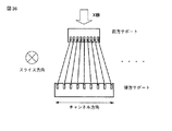
この問題を解決するため、例えば図36に示すように、検出器の20チャンネル程度をカバーするモジュール構造のコリメータ(以下、「モジュール型コリメータ」と呼ぶ。)が提案されている。このモジュール型コリメータは、図36に示す様に、チャンネル方向に沿ってX線検出器の検出面を全てカバーするように複数配置される。モジュール型コリメータは、前方サポートと後方サポートとを有しており、それぞれにはコリメータ単板を挿入する溝が形成されている。この溝は、コリメータ単板をX線焦点に向かせる必要があるため、前方サポートと後方サポートにそれぞれピッチが異なるように形成されている。これにより、前方サポートと後方サポートで対になっている溝にコリメータ単板を挿入することで、コリメータ単板群は裾広がりの構成を成し、結果的に全てのコリメータ単板がX線焦点を向くように形成される。 In order to solve this problem, for example, as shown in FIG. 36, a collimator having a module structure covering about 20 channels of the detector (hereinafter referred to as “module type collimator”) has been proposed. As shown in FIG. 36, a plurality of the module type collimators are arranged so as to cover the entire detection surface of the X-ray detector along the channel direction. The module-type collimator has a front support and a rear support, and a groove for inserting a collimator single plate is formed in each. Since it is necessary to make the collimator single plate face the X-ray focal point, this groove is formed so that the pitch is different between the front support and the rear support. Thus, by inserting the collimator single plate into the groove paired with the front support and the rear support, the collimator single plate group forms a hem-widening configuration, and as a result, all the collimator single plates are in the X-ray focus. It is formed to face.
この様なモジュール型コリメータは、サポートの端面または中心の単板の基準面からの直角度を調整して組立てることで、X線焦点に対して正対したモジュール型コリメータを形成することができる。また、コリメータ単板のスライス方向の検出範囲が200mm程度以上と、コリメータ単板の平坦化が困難となってくる領域でも、前方及び後方サポートにおいてスライス方向に形成した溝に単板を挿入することで、反りは矯正され、平面度は現行並を維持したコリメータを構成できることを確認している。この結果、検出器とのアライメントも達成することができている。 Such a modular collimator can be assembled by adjusting the perpendicularity from the end face of the support or the reference plane of the center single plate to form a modular collimator facing the X-ray focal point. In addition, even when the collimator single plate has a detection range in the slice direction of about 200 mm or more and flattening of the collimator single plate is difficult, the single plate should be inserted into the grooves formed in the slice direction on the front and rear supports. It has been confirmed that the collimator can be constructed with the warpage corrected and the flatness maintained at the same level as the current one. As a result, alignment with the detector can also be achieved.
しかしながら、以上述べたモジュール型コリメータにおいても、例えば次のような問題がある。 However, the above-described module type collimator also has the following problems, for example.
すなわち、モジュール型コリメータにおいては、検出器モジュールに対し、コリメータを取り付ける際の取り付け面の不安定要因が解消できない。例えば、X線検出においては、10μmレベルのゴミが取り付け面に介在するだけでも、約1m先のX線焦点の位置は拡大されて振られてしまう。そのため、モジュール型コリメータ間のつなぎ目部分で、X線焦点を結ぶ連続性に段差が生まれてしまう。その結果、ポーラーレスポンス特性つまりX線焦点が経時的に移動したとき、検出器に落ちる影の変動分に許容できないアンバランス量が発生することが無視できなくなり、画像にアーチファクトが生じる原因になる。 That is, in the modular collimator, the unstable factor of the mounting surface when the collimator is mounted on the detector module cannot be resolved. For example, in X-ray detection, the position of the X-ray focal point about 1 m ahead is enlarged and shaken even if dust of 10 μm level is interposed on the mounting surface. Therefore, a step is created in the continuity connecting the X-ray focal points at the joint between the module type collimators. As a result, when the polar response characteristic, that is, the X-ray focal point moves with time, it is impossible to ignore the occurrence of an unbalance amount that is unacceptable for the fluctuation of the shadow falling on the detector, which causes an artifact in the image.
本発明は、上記事情に鑑みてなされたもので、X線焦点の連続性を失わず、コリメータ単板の平坦度を維持することで、好適なX線のコリメートを実現することができるX線CT装置用コリメータ、当該コリメータ製造方法、及びX線CT装置を提供することを目的とする。 The present invention has been made in view of the above circumstances, and it is possible to realize a suitable X-ray collimation by maintaining the flatness of a single collimator plate without losing the continuity of the X-ray focal point. It aims at providing the collimator for CT apparatuses, the said collimator manufacturing method, and an X-ray CT apparatus.
本発明は、上記目的を達成するため、次のような手段を講じている。 In order to achieve the above object, the present invention takes the following measures.
請求項1に記載の発明は、X線を曝射するX線曝射ユニットと、被検体を介して前記X線曝射ユニットと対向して配置され検出面に入射したX線を検出するX線検出ユニットと、散乱X線を除去するために前記検出面上に設けられるコリメータユニットと、を具備し、前記コリメータユニットは、所定の方向に沿って配列される複数のコリメータ板と、前記コリメータ板の配列方向に沿って形成された複数の第1の溝を有する第1の支持部材と、前記第1の支持部材と並列して設けられ、前記コリメータ板の配列方向に沿って前記複数の第1の溝と対応するように形成された複数の第2の溝を有する第2の支持部材と、相対する前記第1の溝及び前記第2の溝にはめ込まれた前記複数のコリメータ板の前記検出面側の辺をはめ込むための複数の第3の溝を有し、前記コリメータ板の前記検出面側に設けられる第3の支持部材と、前記第1の溝及び前記第2の溝並びに前記第3の溝にはめ込まれた前記複数のコリメータ板の前記X線曝射ユニット側の辺をはめ込むための複数の第4の溝を有し、前記コリメータ板の前記X線曝射ユニット側に設けられる第4の支持部材と、を有し、前記X線曝射ユニットから前記検出面へ向かうX線入射方向と実質的に平行になるように、前記各コリメータ板を前記第1乃至第4のいずれの溝にもはめ込んで4辺で支持すること、を特徴とするX線コンピュータ断層撮影装置である。
請求項9に記載の発明は、X線を曝射するX線曝射ユニットと、被検体を介して前記X線曝射ユニットと対向して配置され検出面に入射したX線を検出するX線検出ユニットと、を具備するX線コンピュータ断層撮影装置に用いられ、散乱X線を除去するために前記検出面上に設けられるコリメータユニットであって、所定の方向に沿って配列される複数のコリメータ板と、前記コリメータ板の配列方向に沿って形成された複数の第1の溝を有する第1の支持部材と、前記第1の支持部材と並列して設けられ、前記コリメータ板の配列方向に沿って前記複数の第1の溝と対応するように形成された複数の第2の溝を有する第2の支持部材と、相対する前記第1の溝及び前記第2の溝にはめ込まれた前記複数のコリメータ板の前記検出面側の辺をはめ込むための複数の第3の溝を有し、前記コリメータ板の前記検出面側に設けられる第3の支持部材と、前記第1の溝及び前記第2の溝並びに前記第3の溝にはめ込まれた前記複数のコリメータ板の前記X線曝射ユニット側の辺をはめ込むための複数の第4の溝を有し、前記コリメータ板の前記X線曝射ユニット側に設けられる第4の支持部材と、を有し、前記X線曝射ユニットから前記検出面へ向かうX線入射方向と実質的に平行になるように、前記各コリメータ板を前記第1乃至第4のいずれの溝にもはめ込んで4辺で支持すること、を具備することを特徴とするX線コンピュータ断層撮影装置用コリメータである。
請求項17に記載の発明は、X線を曝射するX線曝射ユニットと、被検体を介して前記X線曝射ユニットと対向して配置され検出面に入射したX線を検出するX線検出ユニットと、を具備するX線コンピュータ断層撮影装置に用いられ、散乱X線を除去するために前記検出面上に設けられるコリメータの製造方法であって、前記X線曝射ユニットから前記検出面へ向かうX線入射方向に沿って形成された複数の第1の溝を有する第1の支持ユニットと、前記X線曝射ユニットから前記検出面へ向かうX線入射方向に沿って前記複数の第1の溝と対応するように形成された複数の第2の溝を有する第2の支持ユニットとを、側面部材を用いて組み立て、相対する前記第1の溝及び前記第2の溝にはめ込まれた前記コリメータ板の前記検出面側の辺をはめ込むための複数の第3の溝を有する第3の支持ユニットを、前記第1の支持ユニット及び前記第2の支持ユニットの前記検出面側に固定し、相対する前記第1の溝、前記第2の溝、前記第3の溝のそれぞれにコリメータ単板をはめ込み、第4の支持部材が有する複数の第4の溝に前記複数のコリメータ板の前記X線曝射ユニット側の辺をはめ込むと共に、当該第4の支持部材を前記コリメータ板の前記X線曝射ユニット側に設けることで、前記各コリメータ板の4辺を支持すること、を具備することを特徴とするX線コンピュータ断層撮影装置用コリメータ製造方法である。
According to the first aspect of the present invention, an X-ray exposure unit that emits X-rays, and an X-ray that is disposed to face the X-ray exposure unit via a subject and detects an X-ray incident on a detection surface. A collimator unit provided on the detection surface for removing scattered X-rays, wherein the collimator unit includes a plurality of collimator plates arranged along a predetermined direction, and the collimator A first support member having a plurality of first grooves formed along the arrangement direction of the plates; and provided in parallel with the first support member; A second support member having a plurality of second grooves formed to correspond to the first grooves, and the first collimator plate and the plurality of collimator plates fitted in the second grooves. Plural for fitting the sides on the detection surface side And a third groove, and a third supporting member provided on the detection surface side of the collimator plate, said first grooves and said plurality of fitted into said second groove and said third groove A plurality of fourth grooves for fitting the side of the collimator plate on the X-ray exposure unit side, and a fourth support member provided on the X-ray exposure unit side of the collimator plate. such that said X-ray irradiation unit becomes the X-ray incident direction substantially parallel towards the detection surface, supported by the four sides of each collimator plate is fitted to the first to fourth one groove X-ray computed tomography apparatus characterized by the above.
The invention according to
According to the seventeenth aspect of the present invention, an X-ray exposure unit that emits X-rays, and an X-ray that is disposed to face the X-ray exposure unit via a subject and detects an X-ray incident on a detection surface. A collimator for use in an X-ray computed tomography apparatus comprising a ray detection unit and provided on the detection surface for removing scattered X-rays, wherein the detection is performed from the X-ray exposure unit. A first support unit having a plurality of first grooves formed along the X-ray incident direction toward the surface, and the plurality of the plurality of X-rays along the X-ray incident direction from the X-ray exposure unit toward the detection surface. A second support unit having a plurality of second grooves formed to correspond to the first grooves is assembled using a side member, and is fitted into the opposed first and second grooves. On the detection surface side of the collimator plate A third support unit having a plurality of third grooves for fitting the first support unit and the second support unit to the detection surface side of the first support unit and the second support unit. A collimator single plate is fitted into each of the second groove and the third groove, and the sides on the X-ray irradiation unit side of the plurality of collimator plates are fitted into the plurality of fourth grooves of the fourth support member. And providing the fourth support member on the X-ray irradiation unit side of the collimator plate to support four sides of each collimator plate. X-ray computed tomography It is a collimator manufacturing method for apparatuses.
以上本発明によれば、X線焦点の連続性を失わず、コリメータ単板の平坦度を維持することで、好適なX線のコリメートを実現することができるX線CT装置用コリメータ、当該コリメータ製造方法、及びX線CT装置を実現することができる。 As described above, according to the present invention, a collimator for an X-ray CT apparatus capable of realizing suitable X-ray collimation by maintaining the flatness of a collimator single plate without losing continuity of the X-ray focal point, and the collimator. A manufacturing method and an X-ray CT apparatus can be realized.
以下、本発明の第1実施形態及び第2実施形態を図面に従って説明する。なお、以下の説明において、略同一の機能及び構成を有する構成要素については、同一符号を付し、重複説明は必要な場合にのみ行う。 Hereinafter, first and second embodiments of the present invention will be described with reference to the drawings. In the following description, components having substantially the same function and configuration are denoted by the same reference numerals, and redundant description will be given only when necessary.
(第1実施形態)
図1は、本実施形態に係るX線CT装置10のブロック構成図を示している。同図に示すように、本X線CT装置10は、撮影系Aと処理・表示系Bとから構成されている。以下、それぞれが具備する構成要素について説明する。
(First embodiment)
FIG. 1 shows a block diagram of an
撮影系Aは、被検体にX線を曝射し当該被検体を透過したX線を検出して投影データ(又は生データ)を取得する。なお、X線CTシステムの撮影系には、X線管球と2次元検出器システムとが一体として被検体の周囲を回転する回転/回転(ROTATE/ROTATE) タイプ、リング状に多数の検出素子がアレイされ、X線管球のみが被検体の周囲を回転する固定/回転(STATIONARY/ROTATE)タイプ、電子ビームを偏向させることで電子的にX線源の位置をターゲット上で移動させるタイプ等様々なタイプがあり、いずれのタイプでも本発明を適用可能である。ここでは、現在、主流を占めている回転/回転タイプのX線CT装置を例として説明する。 The imaging system A obtains projection data (or raw data) by exposing the subject to X-rays and detecting the X-rays transmitted through the subject. The X-ray CT system has an X-ray tube and a two-dimensional detector system that rotate around the subject as a single unit (ROTATE / ROTATE). Is a fixed / rotation (STATIONARY / ROTATE) type in which only the X-ray tube rotates around the subject, a type in which the position of the X-ray source is moved electronically on the target by deflecting the electron beam, etc. There are various types, and the present invention can be applied to any type. Here, a rotation / rotation type X-ray CT apparatus, which currently occupies the mainstream, will be described as an example.
図1に示すように、撮影系Aは、X線管球101、回転リング102、2次元検出器システム103、データ収集回路(DAS)104、非接触データ伝送装置105、架台駆動部107、スリップリング108、X線管球側コリメータ及びX線検出器側コリメータ(共に図1には図示せず)を有している。
As shown in FIG. 1, the imaging system A includes an
X線管球101は、X線を発生する真空管であり、回転リング102に設けられている。当該X線管球101には、X線の曝射に必要な電力(管電流、管電圧)が高電圧発生装置109からスリップリング108を介して供給される。X線管球101は、供給された高電圧により電子を加速させターゲットに衝突させることで、有効視野領域FOV内に載置された被検体に対してX線を曝射する。
The
なお、X線管球101と被検体との間には、当該X線管球101から曝射されるX線ビームの形状をコーン状(四角錐状)又はファンビーム状に整形するX線管球側コリメータ(図示せず)が設けられている。
An X-ray tube that shapes the shape of the X-ray beam exposed from the
2次元検出器システム103は、被検体を透過したX線を検出する検出器システムであり、X線管球101に対向する向きで回転リング102に取り付けられている。当該2次元検出器システム103には、シンチレータとフォトダイオードとの組み合わせで構成される複数の検出素子が検出面を形成し、被検体の体軸方向(スライス方向)とそれに直交するチャンネル方向とに関してマトリクス状に配列されている。
The two-
なお、検出素子において入射X線を電荷に変換する方式として、直接変換方式と間接変換方式とがある。本実施形態は、いずれの方式にも拘泥されない。 There are a direct conversion method and an indirect conversion method as a method of converting incident X-rays into electric charges in the detection element. This embodiment is not limited to any method.
X線管球101及び検出器システム103は、回転リング102に設けられている。この回転リング102は、架台駆動部107により駆動され、1回転あたり1秒以下という高速で被検体の回りを回転する。
The
データ収集回路(DAS)104は、DASチップが配列された複数のデータ収集素子列を有し、2次元検出器システム103で検出されたM×Nの全チャンネルに関する膨大なデータ(1ビューあたりのM×Nチャンネル分のデータを以下「生データ」という)を入力し、増幅処理、A/D変換処理等の後、一括して光通信を応用した非接触データ伝送装置105を介して固定側のデータ処理ユニットに伝送する。
The data acquisition circuit (DAS) 104 has a plurality of data acquisition element arrays in which DAS chips are arranged, and has a large amount of data (all per view) about all M × N channels detected by the two-
X線検出器側コリメータは、2次元検出器システム103の各検出素子に入射するX線を整形するものであり、2次元検出器システム103のX線入射側に設けられる。
The X-ray detector side collimator shapes the X-rays incident on each detection element of the two-
次に、処理・表示系Bについて説明する。処理・表示系Bは、前処理装置106、高電圧発生装置109、ホストコントローラ110、記憶装置111、再構成装置114、入力装置115、表示装置116、画像処理部118、ネットワーク通信装置119、データ/制御バス300を具備している。
Next, the processing / display system B will be described. The processing / display system B includes a preprocessing device 106, a high
前処理装置106は、非接触データ伝送装置105を介して、DAS104から生データを受け取り、感度補正やX線強度補正を実行する。なお、当該前処理装置106によって前処理が施された生データは、「投影データ」と呼ばれる。
The preprocessing device 106 receives raw data from the
架台駆動部107は、診断用開口内に挿入された被検体の体軸方向に平行な中心軸のまわりに、X線管球101と2次元検出器システム103とを一体で回転させる等の駆動制御を行う。
The
高電圧発生装置109は、スリップリング108を介して、X線の曝射に必要な電力をX線管球101に供給する装置であり、高電圧変圧器、フィラメント加熱変換器、整流器、高電圧切替器等から成る。この高電圧発生装置109によるX線管球101への高電圧供給は、スリップリング108により行われる。
The
ホストコントローラ110は、撮影処理、データ処理、画像処理等の各種処理等の各処理に関する統括的な制御を行う。
The
記憶装置111は、収集した生データ、投影データ、CT画像データ等の画像データを記憶する。
The
再構成装置114は、所定の再構成パラメータ(再構成領域サイズ、再構成マトリクスサイズ、関心部位を抽出するための閾値等)に基づいて投影データを再構成処理することで、所定のスライス分の再構成画像データを生成する。一般に、再構成処理には、コーンビーム再構成(Feldkamp法、ASSR法など)とファンビーム再構成とがあるが、いずれの手法も実行可能である。
The
入力装置115は、キーボードや各種スイッチ、マウス等を備え、オペレータを介してスライス厚やスライス数等の各種スキャン条件を入力可能な装置である。
The
画像処理部118は、再構成装置114により生成された再構成画像データに対して、ウィンドウ変換、RGB処理等の表示のための画像処理を行い、表示装置116に出力する。また、画像処理部118は、オペレータの指示に基づき、任意断面の断層像、任意方向からの投影像、3次元表面画像等のいわゆる疑似3次元画像の生成を行い、表示装置116に出力する。出力された画像データは、表示装置116においてX線CT画像として表示される。
The
ネットワーク通信装置119は、ネットワークを介して、他の装置やRIS(Ragiology Information System)等のネットワークシステムと種々のデータの送受信を行う。
The
データ/制御バス300は、各ユニット間を接続し、各種データ、制御信号、アドレス情報等を送受信するための信号線である。
The data /
(コリメータ)
次に、X線検出器側コリメータの詳細について説明する。このX線検出器側コリメータは、スライス方向の検出範囲が比較的大きくなった場合であっても、X線焦点の連続性、コリメータ単板の平坦度の維持を担保する構造を有している。
(Collimator)
Next, details of the X-ray detector side collimator will be described. This X-ray detector side collimator has a structure that ensures the continuity of the X-ray focus and the flatness of the collimator single plate even when the detection range in the slice direction becomes relatively large. .
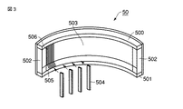
図2は、X線検出器側コリメータ50の設置態様の概略を説明するための図である。同図に示すように、X線検出器側コリメータ50は、2次元検出器システム103のX線入射側において、2次元検出器システム103の形状に沿って(すなわち、円弧状に)設置される。
FIG. 2 is a diagram for explaining an outline of an installation mode of the X-ray
図3は、X線検出器側コリメータ50の構成を説明するための図である。同図に示すように、X線検出器側コリメータ50は、上方サポート500、下方サポート501、側面部材502、突き当て板503、コリメータ単板504を有している。なお、サポート500、サポート501については、スライス方向に沿って配置される被検体の上下を基準として、上方及び下方を定義した。この定義は便宜上のものであり、従ってサポートに関する上下の区別は必須のものではない。
FIG. 3 is a diagram for explaining the configuration of the X-ray
上方サポート500及び下方サポート501は、それぞれ2次元検出器システム103の形状に対応した円弧形状に形成されており、また、コリメータ単板504を挿入するための溝505を有している。この溝505は、挿入されたコリメータ単板を含む平面内にX線焦点が存在するように、X線入射方向に沿って同ピッチで形成されている。上方サポート500と下方サポート501とは、対応する溝505が互いに対向するように、側面部材502によって並列して固定される。
The
なお、溝505は、図4に示すように、y軸方向(チャンネル方向)から見た場合三角形状を有している。これは、溝505をコリメータ単板504へ挿入する際の利便性を考慮したものである。しかしながら、これに拘泥することなく、コリメータ単板504を支持するものであれば、溝505はどのような形状であってもよい。
As shown in FIG. 4, the
突き当て板503は、2次元検出器システム103の形状(すなわち、上方サポート500及び下方サポート501の形状)に対応した円弧形状に形成された板であり、上方サポート500及び下方サポート501が有する溝505と同ピッチで形成された溝506を有する。この突き当て板503は、X線耐性、加工性、X線透過性、機械構造的強度の良好な素材、例えばポリエチレンテレフタレート、エポキシ樹脂その他のカーボンファイバー樹脂を用いて生成されている。突き当て板503は、自身の溝506と上方サポート500及び下方サポート501の溝505とが対応するように、上方サポート500及び下方サポート501の円弧形状の外側(外円弧側、すなわちX線検出器の検出面側)において固定される。
The
コリメータ単板504は、タングステン、モリブデン等の剛性、X線遮断性、機械構造的強度に優れた金属等から形成される。このコリメータ単板504は、図4に示すように上方サポート500及び下方サポート501の溝505、及び突き当て板503の溝506に挿入され、その3辺によって支持されながら、スライス方向に対して略垂直な方向に沿って複数配置される。なお、溝505及び溝506とコリメータ単板504との間は、接着剤によって固定される。
The collimator
(突き当て板の溝形成方法)
次に、突き当て板503の溝506の形成方法について説明する。
(Method for forming groove of abutting plate)
Next, a method for forming the
図5は、突き当て板503の溝506の形成方法を説明するための図である。同図において、まず、例えば2〜3mm厚程度のカーボン繊維強化プラスチック(CFRP樹脂)などX線透過率の高い材料を用いて、(溝506のない)突き当て板503の形状・サイズを有するCFRP板51を形成する。
FIG. 5 is a diagram for explaining a method of forming the
次に、溝506のチャネル方向の幅と同等の厚みを有するブレード52を用いて、CFRP板51にスライス方向に沿った溝506を形成する。このとき、図6に示すように、コリメータ単板504挿入側(X線管球側)の溝幅Aとコリメータ単板504突き当て側(X線検出器側)の溝幅aとを比較した場合、溝幅A>溝幅aとなるように、CFRP板51の厚み方向に対してテーパ状に溝506を形成する。これは、図7に示すように、上方サポート500及び下方サポート501の円弧面に沿って固定するために突き当て板503を円弧状に変形した場合に、溝幅Aと溝幅aとを略等しくし、突き当て板503に対してコリメータ単板504が略垂直に設置されるようにするためである。
Next, the
従って、溝幅Aの値は、突き当て板503を上方サポート500及び下方サポート501に固定した状態(すなわち、図7の状態)で溝幅Aと溝幅aとを略等しくするためには、当該固定した状態の突き当て板503の曲率及び溝幅aに基づいて決定することが好ましい。
Therefore, the value of the groove width A is set so that the groove width A and the groove width a are substantially equal in a state where the
また、突き当て板503を上方サポート500及び下方サポート501に固定した状態で溝幅A>溝幅aとなるように、図6に示す状態で溝幅A>>溝幅aとして溝506を形成する構成(すなわち溝幅Aを溝幅aよりも明らかに大きくする構成)としてもよい。この様な構成とすれば、突き当て板503を上方サポート500及び下方サポート501に固定した状態でも溝506はテーパ形状を有することになり、コリメータ単板504を挿入し易く、且つセルフアライメントで調芯することができる。
Further, the
なお、本実施形態では、突き当て板503は、上方サポート500及び下方サポート501をカバーする一体物で構成した(図3参照)。しかしながら、これに拘泥する趣旨ではなく、例えば溝加工の制約上等の理由により、複数で上方サポート500及び下方サポート501をカバーする分割構造にしても良い。分割構成とした場合には、そのつなぎ目部分はテーパ形状にしておき、オーバーラップさせるか、ちょうどコリメータ単板の影に配置することが好ましい。これにより、つなぎ目の影響を回避することができる。
In the present embodiment, the abutting
(コリメータ製造方法)
次に、第1の実施形態に係る検出器側コリメータ50の製造方法について説明する。
(Collimator manufacturing method)
Next, a method for manufacturing the detector-
図8は、検出器側コリメータ50の製造工程の流れを示したフローチャートである。同図に示すように、まず、上方サポート500、下方サポート501と、側面部材502とを組み立て、X線検出器側コリメータ50の外枠を形成する(ステップS1)。
FIG. 8 is a flowchart showing the flow of the manufacturing process of the detector-
次に、上方サポート500及び下方サポート501にそれぞれ形成された溝505に接着剤を塗布し(ステップS2)、突き当て板503を円弧形状に弾性変形させて、上方サポート500及び下方サポート501の外周側の円弧側面にネジ締め等で組み立てる(ステップS3)。
Next, an adhesive is applied to the
次に、突き当て板503の溝506に接着剤を塗布し(ステップS4)、コリメータ単板504を上方サポート500及び下方サポート501の溝505、突き当て板503の溝506に挿入する(ステップS5)。
Next, an adhesive is applied to the
次に、硬化炉に入れ接着剤を硬化させることにより、コリメータ単板504の3辺が溝505及び溝506において支持された検出器側コリメータ50が完成する(ステップS6)。
Next, the
以上述べた構成によれば、以下の効果を得ることができる。 According to the configuration described above, the following effects can be obtained.
本検出器側コリメータは一体型構造をしており、その上下サポートにおいて形成された溝によって、コリメータ単板のX線焦点に対する角度が決定される。そのため、従来のモジュール型コリメータの様に複数モジュール間におけるX線焦点のずれが発生することがなく、X線焦点の連続性を確保することができる。その結果、好適なX線のコリメートを実現することができる。 The detector-side collimator has an integral structure, and the angle of the collimator single plate with respect to the X-ray focal point is determined by the grooves formed in the upper and lower supports. Therefore, unlike the conventional module type collimator, the X-ray focal point is not shifted between a plurality of modules, and the continuity of the X-ray focal point can be ensured. As a result, a suitable X-ray collimation can be realized.
また、本検出器側コリメータは一体型構造であるから、従来のモジュール型コリメータの様に複数モジュール間のアライメントを必要としない。従って、X線CT装置の設置及びメンテナンスにおける作業負担を軽減させることができる。 Further, since the detector-side collimator has an integral structure, alignment between a plurality of modules is not required unlike a conventional module-type collimator. Therefore, it is possible to reduce the work burden in the installation and maintenance of the X-ray CT apparatus.
また、本検出器側コリメータはコリメータ単板の3辺を支持する構成となっている。従って、従来の2辺を支持する構成と比較して、コリメータ単板の平坦度を好適に維持することができる。その結果、コリメータ単板の反りを修正するためのメンテナンスをする必要がなくなり、作業負担を軽減させることができると共に、X線CT画像の撮影において適切なX線のコリメートを実現することができる
(第2の実施形態)
次に、本発明の第2の実施形態に係る検出器側コリメータ50、及びこれを具備するX線CT装置10について説明する。第2の実施形態は、第1の実施形態に比して、コリメータ単板の平坦性維持をさらに担保することを目的とするものである。
Further, the detector-side collimator is configured to support the three sides of the collimator single plate. Therefore, the flatness of the collimator single plate can be suitably maintained as compared with the conventional configuration supporting two sides. As a result, it is not necessary to perform maintenance for correcting the warpage of the collimator single plate, the work load can be reduced, and appropriate X-ray collimation can be realized in the imaging of X-ray CT images. Second embodiment)
Next, the detector-
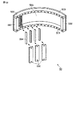
図9は、第2の実施形態に係るX線CT装置10が有する検出器側コリメータ50の構成を示した図である。同図に示すように、本実施形態に係る検出器側コリメータ50は、図3に示した構成に加えて、内周側の円弧側面にガイド板510をさらに具備する。
FIG. 9 is a diagram illustrating a configuration of a detector-
ガイド板510は、検出器側コリメータ50の形状(すなわち、上方サポート500及び下方サポート501の形状)に対応した円弧形状に形成された板であり、溝505及び溝506と同ピッチで形成されたスリット511を有する。このスリット511は、少なくともコリメータ単板504を通過させ得る幅及び高さを有している。
The
また、ガイド板510は、突き当て板503と同様に、X線耐性、加工性、X線透過性、機械構造的強度の良好な素材、例えばポリエチレンテレフタレート、エポキシ樹脂その他のカーボンファイバー樹脂を用いて生成されている。ガイド板510は、自身のスリット511と溝505及び溝506とが対応するように、上方サポート500及び下方サポート501の円弧形状の内側(内円弧側)において、図10(a)に示す様に固定される。
The
なお、ガイド板510は、次の様にして製造することができる。すなわち、図10(b)に示すように、例えばカーボン繊維強化プラスチック(CFRP樹脂)などX線透過率の高い材料を用いて、(スリット511のない)ガイド板510の形状・サイズを有するCFRP板53を形成する。
The
次に、スリット511のチャネル方向の幅と同等の厚みを有するブレード54を用いて、CFRP板53にスライス方向に沿ったスリット511を形成することで、ガイド板510を製造することができる。なお、図10(c)に、スリット511に沿った平面によるガイド板510の断面図を例示した。
Next, the
(コリメータ製造方法)
次に、第2の実施形態に係る検出器側コリメータ50の製造方法について説明する。
(Collimator manufacturing method)
Next, a method for manufacturing the detector-
図11は、検出器側コリメータ50の製造工程の流れを示したフローチャートである。同図におけるステップS11乃至ステップS14までの工程は、図8に示したステップS1乃至ステップS4までの工程と略同様であるので、その説明は省略する。
FIG. 11 is a flowchart showing the flow of the manufacturing process of the detector-
突き当て板503の溝506に接着剤を塗布した後、スリット入りガイド板510を上方サポート500及び下方サポート501に組み付ける(ステップS15)。この組み付けの後、ガイド板510のスリット511からコリメータ単板504を挿入し、コリメータ単板504を上方サポート500及び下方サポート501の溝505、突き当て板503の溝506に挿入する(ステップS16)。
After applying an adhesive to the
次に、スリット511に接着剤を塗布した後(ステップS17)、硬化炉に入れ接着剤を硬化させることにより、コリメータ単板504の4辺が溝505、溝506、スリット511において支持された検出器側コリメータ50が完成する(ステップS18)。
Next, after the adhesive is applied to the slit 511 (step S17), the adhesive is cured by putting it in a curing furnace, so that the four sides of the collimator
以上述べた構成によれば、第1の実施形態において説明した効果に加えて、コリメータ単板の平坦性をより高精度に維持することができる。従って、スライス方向の検出範囲がより広大な場合であっても、コリメータ単板の平坦性を好適に維持することが可能である。 According to the configuration described above, in addition to the effects described in the first embodiment, the flatness of the collimator single plate can be maintained with higher accuracy. Therefore, even if the detection range in the slice direction is wider, it is possible to favorably maintain the flatness of the collimator single plate.
(第3の実施形態)
本発明の第3の実施形態に係る検出器側コリメータ、及びこれを具備するX線CT装置について説明する。本検出器側コリメータは、上方サポート、下方サポート、一体型である突き当て板、一体型である内径カバーにより、コリメータ単板を4辺によって支持する構造をもつものである。
(Third embodiment)
A detector-side collimator according to a third embodiment of the present invention and an X-ray CT apparatus including the same will be described. This detector-side collimator has a structure in which a collimator single plate is supported by four sides by an upper support, a lower support, an integral butting plate, and an integral inner diameter cover.
図12は、第3の実施形態に係るX線CT装置10が有する検出器側コリメータ50の構成を示した図である。同図に示すように、本実施形態に係る検出器側コリメータ50は、上方サポート500、下方サポート501、側面部材502、突き当て板503、一体型である内径カバー520、複数のコリメータ単板504を具備している。
FIG. 12 is a diagram illustrating a configuration of a detector-
突き当て板503は一体構造であり、コリメータ単板504の一辺を挿入するための溝506を有している。
The
内径カバー520は、上方サポート500及び下方サポート501の形状(すなわち、円弧形状)に形成された板である。内径カバー520は、コリメータ単板504を上方サポート500及び下方サポート501の内径側から支持するカバーであり、コリメータ単板504の一辺を挿入するための溝521を有している。この内径カバー520は、突き当て板503と同様に、X線耐性、加工性、X線透過性、機械構造的強度の良好な素材、例えばポリエチレンテレフタレート、エポキシ樹脂その他のカーボンファイバー樹脂を用いて生成されている。
The
図13は、内径カバー520の溝521の形成方法を説明するための図である。同図において、まず、例えば2〜3mm厚程度のカーボン繊維強化プラスチック(CFRP樹脂)などX線透過率の高い材料を用いて、(溝521のない)内径カバー520の形状・サイズを有するCFRP板55を形成する。
FIG. 13 is a view for explaining a method of forming the
次に、溝521のチャネル方向の幅と同等の厚みを有するブレード52を用いて、CFRP板55にスライス方向に沿った溝521を形成する。このとき、図14に示すように、コリメータ単板504挿入側(X線検出器側)の溝幅Bとコリメータ単板504突き当て側(X線管球側)の溝幅bとを比較した場合、溝幅B<溝幅bとなるように、CFRP板55の厚み方向に対してテーパ状に溝521を形成する。これは、図15に示すように、上方サポート500及び下方サポート501の円弧面に沿って固定するために内径カバー520を円弧状に変形した場合に、溝幅Bと溝幅bとを略等しくし、内径カバー520に対してコリメータ単板504が略垂直に設置されるようにするためである。
Next, the
従って、溝幅Bの値は、内径カバー520を上方サポート500及び下方サポート501に固定した状態(すなわち、図15の状態)で溝幅Bと溝幅bとを略等しくするためには、当該固定した状態の内径カバー520の曲率及び溝幅bに基づいて決定することが好ましい。
Therefore, in order to make the groove width B and the groove width b substantially equal in a state where the
(コリメータ製造方法)
次に、本実施形態に係る検出器側コリメータ50の製造方法について説明する。
(Collimator manufacturing method)
Next, a method for manufacturing the detector-
図16は、検出器側コリメータ50の製造工程の流れを示したフローチャートである。同図におけるステップS21乃至ステップS24までの工程は、図8に示したステップS1乃至ステップS4までの工程と略同様であるので、その説明は省略する。
FIG. 16 is a flowchart showing the flow of the manufacturing process of the detector-
突き当て板503の溝506に接着剤を塗布した後、コリメータ単板504を、上方サポート500及び下方サポート501の溝505、突き当て板503の溝506に挿入する(ステップS25)。
After applying an adhesive to the
次に、内径カバー520の溝521に接着剤を塗布した後(ステップS26)、各コリメータ単板504を各溝521に挿入しながら内径カバー520を、上方サポート500、下方サポート501、側面部材502に装着する(ステップS27)。なお、各コリメータ単板504を各溝521に挿入させる際、必要に応じて、内径カバー520を挿入方向に沿って押圧する、又はコリメータ単板504側及び内径カバー520の少なくとも一方を振動させながら押圧するようにしてもよい。
Next, after applying an adhesive to the
次に、コリメータ50を硬化炉に入れ接着剤を硬化させる(ステップS28)。以上の各処理により、コリメータ単板504の4辺が溝505、溝506、溝521において支持された検出器側コリメータ50が完成する。
Next, the
なお、溝505、溝506、溝521への接着剤は、必須ではない。例えば、接着剤がなくても十分に各コリメータ単板504を支持できる場合には、少なくとも一つの溝あるいは全ての溝への接着剤塗布を省略してもよい。この点は、他の実施形態においても同様である。
Note that the adhesive to the
(変形例)
次に、本実施形態の変形例について説明する。本変形例に係る検出器側コリメータ50は、溝521を有しない内径カバーにより、コリメータ単板504の4辺のうちの一辺を支持するものである。
(Modification)
Next, a modification of this embodiment will be described. The detector-
図17は、本変形例に係る検出器側コリメータ50の構成を示した図である。同図に示すように、検出器側コリメータ50は、一体型であり且つコリメータ単板504を挿入するための溝を有しない内径カバー525を具備している。
FIG. 17 is a diagram showing a configuration of a detector-
内径カバー525は、溝521が形成されていない点以外は、内径カバー520の構成と同様である。この内径カバー525は、図18に示すように、各コリメータ単板504の一辺(すなわち、X線管101側の一辺)を押しつけるようにして、上方サポート500、下方サポート501、側面部材502に組み付けられる。コリメータ単板504は、内径カバー525によって押圧されることで、その一辺を支持される。
The
(コリメータ製造方法)
次に、本変形例に係る検出器側コリメータ50の製造方法について説明する。
(Collimator manufacturing method)
Next, a method for manufacturing the detector-
図19は、検出器側コリメータ50の製造工程の流れを示したフローチャートである。同図におけるステップS31乃至ステップS35までの工程は、図16に示したステップS21乃至ステップS25までの工程と略同様であるので、その説明は省略する。
FIG. 19 is a flowchart showing the flow of the manufacturing process of the detector-
コリメータ単板504の挿入後、内径カバー525が各コリメータ単板504のX線管球101側の一辺を押圧するように、内径カバー525を上方サポート500、下方サポート501、側面部材502に組み付ける(ステップS36)。
After the collimator
次に、コリメータ50を硬化炉に入れ接着剤を硬化させる(ステップS37)。以上の各処理により、コリメータ単板504の4辺が溝505、溝506、内径カバー525において支持された検出器側コリメータ50が完成する。
Next, the
以上述べた構成によれば、第1の実施形態と同様の効果に加えて、次の新たな効果を実現することができる。 According to the configuration described above, in addition to the same effects as those of the first embodiment, the following new effects can be realized.
本検出器側コリメータでは、コリメータ単板は、その4辺によって支持される。従って、従来の二辺支持、三辺支持の場合に比して、コリメータ単板の平坦度が高い検出器側コリメータを実現することができる。その結果、理想的なコリメーションを実現することができる。特に、スライス方向の検出範囲がより広大な場合であっても、コリメータ単板の平坦性を好適に維持することが可能である。 In this detector side collimator, the collimator single plate is supported by its four sides. Therefore, a detector-side collimator having a high flatness of a single collimator plate can be realized as compared with the conventional two-side support and three-side support. As a result, ideal collimation can be realized. In particular, even if the detection range in the slice direction is wider, it is possible to favorably maintain the flatness of the collimator single plate.
また、コリメータ単板は、4辺によって均等に支持される。このため、1回転あたり1秒以下という高速で被検体の体軸を中心として回転する際の大きな加速度発生時においてもコリメータ単板の剛性を高く維持できる。コリメータ単板の平坦性が狂うことも少ない。その結果、メンテナンス時におけるコリメータ単板の平坦性回復に関する作業を軽減することができる。 Moreover, the collimator single plate is equally supported by the four sides. For this reason, the rigidity of the collimator single plate can be maintained high even when a large acceleration is generated when rotating around the body axis of the subject at a high speed of 1 second or less per rotation. The flatness of the collimator single plate is less likely to go wrong. As a result, it is possible to reduce work related to restoration of flatness of the collimator single plate during maintenance.
(第4の実施形態)
本発明の第4の実施形態に係る検出器側コリメータ、及びこれを具備するX線CT装置について説明する。本検出器側コリメータは、上方サポート、下方サポート、一体型である突き当て板、モジュール型である内径カバーにより、コリメータ単板を4辺によって支持する構造をもつものである。
(Fourth embodiment)
A detector-side collimator and an X-ray CT apparatus including the same according to a fourth embodiment of the present invention will be described. This detector-side collimator has a structure in which a collimator single plate is supported by four sides by an upper support, a lower support, an integral butting plate, and a module-type inner diameter cover.
図20Aは、第4の実施形態に係るX線CT装置10が有する検出器側コリメータ50の構成を示した図である。同図に示すように、本実施形態に係る検出器側コリメータ50は、上方サポート500、下方サポート501、側面部材502、突き当て板503、モジュール型である内径カバー530、複数のコリメータ単板504を具備している。
FIG. 20A is a diagram illustrating a configuration of a detector-
突き当て板503は一体構造であり、コリメータ単板504の一辺を挿入するための溝506を有している。
The
内径カバー530は、上方サポート500及び下方サポート501の曲率(すなわち、円弧の曲率)に対応した円弧状の形状をチャンネル方向に関して持つ板であり、チャンネル方向に沿って複数配列される。内径カバー530は、コリメータ単板504を上方サポート500及び下方サポート501の内径側から支持するカバーであり、コリメータ単板504の一辺を挿入するための溝531を有している。この内径カバー530は、突き当て板503と同様に、X線耐性、加工性、X線透過性、機械構造的強度の良好な素材、例えばポリエチレンテレフタレート、エポキシ樹脂その他のカーボンファイバー樹脂を用いて生成されている。
The
また、内径カバー530は、溝531とは異なる溝532を有している。内径カバー530をチャンネル方向に沿って複数配列した場合には、隣り合う内径カバー530の溝532は、図20B、図20Cに示すように、コリメータ単板504を挿入するための溝531を形成する。この様に隣り合う内径カバー530の溝532によって形成される溝531にコリメータ単板504を挿入することで、チャンネル方向に配列された内径カバー530のつなぎ目におけるX線検出への影響を、回避することができる。
Further, the
なお、内径カバー530は、図20Bの様に一定間隔dをもってチャンネル方向に配列される構成、或いは図25Dの様に隣同士が接触するようにチャンネル方向に配列される構成、のいずれであってもよい。いずれの構成であっても、溝532のチャンネル方向幅は、隣り合う内径カバー530の溝532により溝533が形成されるように設計される。
The
このような内径カバー530は、第3の実施形態に係る内径カバー520と略同様の手法によって生成することができる。
Such an
(コリメータ製造方法)
次に、本実施形態に係る検出器側コリメータ50の製造方法について説明する。
(Collimator manufacturing method)
Next, a method for manufacturing the detector-
図21は、検出器側コリメータ50の製造工程の流れを示したフローチャートである。同図におけるステップS41乃至ステップS45までの工程は、図19に示したステップS31乃至ステップS35までの工程と略同様であるので、その説明は省略する。
FIG. 21 is a flowchart showing the flow of the manufacturing process of the detector-
コリメータ単板504の挿入後、モジュール化された各内径カバー530の溝531及び532に接着剤を塗布した後(ステップS46)、各コリメータ単板504を各溝531に挿入しながら各内径カバー530を、上方サポート500、下方サポート501、側面部材502に組み付ける(ステップS47)。なお、各コリメータ単板504を各溝531及び溝532に挿入させる際、必要に応じて、内径カバー530を挿入方向に沿って押圧する、又はコリメータ単板504側及び内径カバー530の少なくとも一方を振動させながら押圧するようにしてもよい。
After the collimator
次に、コリメータ50を硬化炉に入れ接着剤を硬化させる(ステップS48)。以上の各処理により、コリメータ単板504の4辺が溝505、溝506、溝521において支持された検出器側コリメータ50が完成する。
Next, the
(変形例)
次に、本実施形態の変形例について説明する。本変形例に係る検出器側コリメータ50は、溝532を有しないモジュール化された内径カバーにより、コリメータ単板504の4辺のうちの一辺を支持するものである。
(Modification)
Next, a modification of this embodiment will be described. The detector-
図22は、本変形例に係る検出器側コリメータ50の構成を示した図である。同図に示すように、検出器側コリメータ50は、モジュール化され且つコリメータ単板504を挿入するための溝を有しない内径カバー533を具備している。
FIG. 22 is a diagram showing a configuration of a detector-
内径カバー533は、溝531が形成されていない点以外は、内径カバー530の構成と同様である。各内径カバー533は、図18に示した例と同様に、各コリメータ単板504の一辺(すなわち、X線管101側の一辺)を押しつけるようにして、上方サポート500、下方サポート501、側面部材502に組み付けられる。コリメータ単板504は、内径カバー533によって押圧されることで、その一辺を支持される。
The
(コリメータ製造方法)
次に、本変形例に係る検出器側コリメータ50の製造方法について説明する。
(Collimator manufacturing method)
Next, a method for manufacturing the detector-
図23は、検出器側コリメータ50の製造工程の流れを示したフローチャートである。同図におけるステップS51乃至ステップS55までの工程は、図21に示したステップS41乃至ステップS45までの工程と略同様であるので、その説明は省略する。
FIG. 23 is a flowchart showing the flow of the manufacturing process of the detector-
コリメータ単板504の挿入後、内径カバー533が各コリメータ単板504のX線管球101側の一辺を押圧するように、内径カバー533を上方サポート500、下方サポート501、側面部材502に組み付ける(ステップS56)。
After the collimator
次に、コリメータ50を硬化炉に入れ接着剤を硬化させる(ステップS57)。以上の各処理により、コリメータ単板504の4辺が溝505、溝506、内径カバー533において支持された検出器側コリメータ50が完成する。
Next, the
以上述べた構成によれば、第3の実施形態と同様の効果に加えて、次の新たな効果を実現することができる。すなわち、コリメータ単板の一辺を支持する内径カバーは、モジュール化されているため、部分的に分解が可能である。従って、一部のコリメータ単板の調整、交換等が必要である場合、そのコリメータ単板を支持する内径カバーを取り外すのみでよい。結果、メンテナンス時における作業負担や費用を軽減することができる。 According to the configuration described above, in addition to the same effects as those of the third embodiment, the following new effects can be realized. That is, the inner diameter cover that supports one side of the collimator plate is modularized and can be partially disassembled. Accordingly, when adjustment or replacement of some collimator single plates is necessary, it is only necessary to remove the inner diameter cover that supports the collimator single plates. As a result, it is possible to reduce the work burden and cost during maintenance.
(第5の実施形態)
本発明の第5の実施形態に係る検出器側コリメータ、及びこれを具備するX線CT装置について説明する。本検出器側コリメータは、上方サポート、下方サポート、一体型である内径カバー、モジュール型である突き当て板により、コリメータ単板を4辺によって支持する構造をもつものである。
(Fifth embodiment)
A detector-side collimator and an X-ray CT apparatus including the same according to a fifth embodiment of the present invention will be described. This detector-side collimator has a structure in which a collimator single plate is supported by four sides by an upper support, a lower support, an integrated inner diameter cover, and a module-type abutting plate.
図24は、第5の実施形態に係るX線CT装置10が有する検出器側コリメータ50の構成を示した図である。同図に示すように、本実施形態に係る検出器側コリメータ50は、上方サポート500、下方サポート501、側面部材502、モジュール化された突き当て板540、一体型である内径カバー520、複数のコリメータ単板504を具備している。
FIG. 24 is a diagram illustrating a configuration of a detector-
図25Aは、突き当て板540の外観を示した図である。同図に示すように、突き当て板540は、チャンネル方向に沿って複数配列される。突き当て板540は、コリメータ単板504の一辺を挿入するための溝541を有している。この突き当て板540は、突き当て板503と同様に、X線耐性、加工性、X線透過性、機械構造的強度の良好な素材、例えばポリエチレンテレフタレート、エポキシ樹脂その他のカーボンファイバー樹脂を用いて生成されている。また、突き当て板540は、突き当て板503と略同様の手法によって生成することができる(図13、図14、図15等参照)。
FIG. 25A is a view showing the appearance of the
また、突き当て板540は、溝541とは異なる溝542を有している。図25A、図25Bに示すように、突き当て板540をチャンネル方向に沿って複数配列した場合には、隣り合う突き当て板540の溝542は、コリメータ単板504を挿入するための溝543を形成する。この様に隣り合う突き当て板540の溝542によって形成される溝543にコリメータ単板504を挿入することで、チャンネル方向に配列された突き当て板540つなぎ目におけるX線検出への影響を、回避することができる。
The
なお、突き当て板540は、図25Aの様に一定間隔dをもってチャンネル方向に配列される構成、或いは図25Cの様に隣同士が接触するようにチャンネル方向に配列される構成、のいずれであってもよい。いずれの構成であっても、溝542のチャンネル方向幅は、隣り合う突き当て板540の溝542により溝543が形成されるように設計される。
Note that the
(コリメータ製造方法)
次に、本実施形態に係る検出器側コリメータ50の製造方法について説明する。
(Collimator manufacturing method)
Next, a method for manufacturing the detector-
図26は、検出器側コリメータ50の製造工程の流れを示したフローチャートである。同図に示すように、まず、上方サポート500、下方サポート501と、側面部材502とを組み立て、X線検出器側コリメータ50の外枠を形成する(ステップS61)。次に、上方サポート500及び下方サポート501にそれぞれ形成された溝505に接着剤を塗布し(ステップS62)、モジュール化された各突き当て板540を円弧形状に弾性変形させて、上方サポート500及び下方サポート501の外周側の円弧側面にネジ締め等で組み立てる(ステップS63)。
FIG. 26 is a flowchart showing the flow of the manufacturing process of the detector-
次に、各突き当て板540の溝541、溝542に接着剤を塗布し(ステップS64)、コリメータ単板504を上方サポート500及び下方サポート501の溝505、各突き当て板540の溝541に挿入する(ステップS65)。
Next, an adhesive is applied to the
次に、内径カバー520の溝521に接着剤を塗布した後(ステップS66)、各コリメータ単板504を各溝521に挿入しながら内径カバー520を、上方サポート500、下方サポート501、側面部材502に組み付ける(ステップS67)。なお、各コリメータ単板504を各溝521に挿入させる際、必要に応じて、内径カバー520を挿入方向に沿って押圧する、又はコリメータ単板504側及び内径カバー520の少なくとも一方を振動させながら押圧するようにしてもよい。
Next, after applying an adhesive to the
次に、コリメータ50を硬化炉に入れ接着剤を硬化させる(ステップS68)。以上の各処理により、コリメータ単板504の4辺が溝505、溝521、溝541、溝542において支持された検出器側コリメータ50が完成する。
Next, the
(変形例)
次に、本実施形態の変形例について説明する。本変形例に係る検出器側コリメータ50は、溝521を有しない内径カバー525により、コリメータ単板504の4辺のうちの一辺を支持するものである。
(Modification)
Next, a modification of this embodiment will be described. The detector-
図27は、本変形例に係る検出器側コリメータ50の構成を示した図である。同図に示すように、検出器側コリメータ50は、モジュール化された突き当て板540、一体型であり且つコリメータ単板504を挿入するための溝を有しない内径カバー525を具備している。
FIG. 27 is a diagram showing a configuration of a detector-
(コリメータ製造方法)
次に、本変形例に係る検出器側コリメータ50の製造方法について説明する。
(Collimator manufacturing method)
Next, a method for manufacturing the detector-
図28は、検出器側コリメータ50の製造工程の流れを示したフローチャートである。同図におけるステップS71乃至ステップS75までの工程は、図26に示したステップS61乃至ステップS65までの工程と略同様であるので、その説明は省略する。
FIG. 28 is a flowchart showing the flow of the manufacturing process of the detector-
コリメータ単板504の挿入後、内径カバー525が各コリメータ単板504のX線管球101側の一辺を押圧するように、内径カバー525を上方サポート500、下方サポート501、側面部材502に組み付ける(ステップS76)。
After the collimator
次に、コリメータ50を硬化炉に入れ接着剤を硬化させる(ステップS77)。以上の各処理により、コリメータ単板504の4辺が溝505、溝541、内径カバー525において支持された検出器側コリメータ50が完成する。
Next, the
以上述べた構成によれば、第3の実施形態と同様の効果に加えて、次の新たな効果を実現することができる。すなわち、コリメータ単板の一辺を支持する突き当て板は、モジュール化されているため、部分的に分解が可能である。従って、一部のコリメータ単板の調整、交換等が必要である場合、そのコリメータ単板を支持する突き当て板を取り外すのみでよい。結果、メンテナンス時における作業負担や費用を軽減することができる。 According to the configuration described above, in addition to the same effects as those of the third embodiment, the following new effects can be realized. That is, the abutting plate that supports one side of the collimator single plate is modularized and can be partially disassembled. Accordingly, when adjustment or replacement of some collimator single plates is necessary, it is only necessary to remove the butting plate that supports the collimator single plates. As a result, it is possible to reduce the work burden and cost during maintenance.
(第6の実施形態)
本発明の第6の実施形態に係る検出器側コリメータ、及びこれを具備するX線CT装置について説明する。本検出器側コリメータは、上方サポート、下方サポート、突き当て板、上方内径カバー及び下方内径カバーにより、コリメータ単板を4辺によって支持する構造をもつものである。
(Sixth embodiment)
A detector-side collimator and an X-ray CT apparatus including the same according to a sixth embodiment of the present invention will be described. This detector-side collimator has a structure in which a collimator single plate is supported by four sides by an upper support, a lower support, a butting plate, an upper inner diameter cover, and a lower inner diameter cover.
図29は、第6の実施形態に係るX線CT装置10が有する検出器側コリメータ50の構成を示した図である。同図に示すように、本実施形態に係る検出器側コリメータ50は、上方サポート500、下方サポート501、側面部材502、突き当て板503、一体型である上方内径カバー550、一体型である下方内径カバー551、複数のコリメータ単板504を具備している。
FIG. 29 is a diagram illustrating a configuration of a detector-
上方内径カバー550及び下方内径カバー551は、それぞれ上方サポート500及び下方サポート501の曲率(すなわち、円弧の曲率)に対応した円弧状の形状をチャンネル方向に関して持つ板である。上方内径カバー550は、コリメータ単板504を上方サポート500の内径側から支持するカバーであり、コリメータ単板504の一辺を挿入するための溝552を有している。この上方内径カバー550及び下方内径カバー551は、突き当て板503と同様に、X線耐性、加工性、X線透過性、機械構造的強度の良好な素材、例えばポリエチレンテレフタレート、エポキシ樹脂その他のカーボンファイバー樹脂を用いて生成されている。
The upper
なお、上方内径カバー550及び下方内径カバー551は、第3の実施形態に係る内径カバー520と略同様の手法によって生成することができる。
Note that the upper
(コリメータ製造方法)
次に、本実施形態に係る検出器側コリメータ50の製造方法について説明する。
(Collimator manufacturing method)
Next, a method for manufacturing the detector-
図30は、検出器側コリメータ50の製造工程の流れを示したフローチャートである。同図におけるステップS81乃至ステップS85までの工程は、図16に示したステップS21乃至ステップS25までの工程と略同様であるので、その説明は省略する。
FIG. 30 is a flowchart showing the flow of the manufacturing process of the detector-
コリメータ単板504の挿入後、上方内径カバー550の溝552に接着剤を塗布した後(ステップS86)、各コリメータ単板504を各溝552に挿入しながら、上方内径カバー550を上方サポート500、側面部材502に組み付ける。また、下方内径カバー551の溝552に接着剤を塗布した後、各コリメータ単板504を各溝552に挿入しながら、下方内径カバー550を下方サポート501、側面部材502に組み付ける(ステップS87)。なお、各コリメータ単板504を各溝552に挿入させる際、必要に応じて、上方内径カバー550(下方内径カバー551)を挿入方向に沿って押圧する、又はコリメータ単板504側及び上方内径カバー550(下方内径カバー551)の少なくとも一方を振動させながら押圧するようにしてもよい。
After the collimator
次に、コリメータ50を硬化炉に入れ接着剤を硬化させる(ステップS88)。以上の各処理により、コリメータ単板504の4辺が溝505、溝506、溝552において支持された検出器側コリメータ50が完成する。
Next, the
(変形例)
次に、本実施形態の変形例について説明する。本変形例に係る検出器側コリメータ50は、溝552を有しない上方内径カバー555及び下方内径カバー556により、コリメータ単板504の4辺のうちの一辺を支持するものである。
(Modification)
Next, a modification of this embodiment will be described. The detector-
図31は、本変形例に係る検出器側コリメータ50の構成を示した図である。同図に示すように、検出器側コリメータ50は、コリメータ単板504を挿入するための溝を有しない上方内径カバー555及び下方内径カバー556を具備している。
FIG. 31 is a diagram showing a configuration of a detector-
上方内径カバー555及び下方内径カバー556は、溝552が形成されていない点以外は、上方内径カバー550及び下方内径カバー551の構成と同様である。上方内径カバー555及び下方内径カバー556は、図32に示した例と同様に、各コリメータ単板504の一辺(すなわち、X線管101側の一辺)を押しつけるようにして、上方サポート500等に組み付けられる。コリメータ単板504は、上方内径カバー555及び下方内径カバー556によって押圧されることで、その一辺を支持される。
The upper
(コリメータ製造方法)
次に、本変形例に係る検出器側コリメータ50の製造方法について説明する。
(Collimator manufacturing method)
Next, a method for manufacturing the detector-
図33は、検出器側コリメータ50の製造工程の流れを示したフローチャートである。同図におけるステップS91乃至ステップS95までの工程は、図30に示したステップS81乃至ステップS85までの工程と略同様であるので、その説明は省略する。
FIG. 33 is a flowchart showing the flow of the manufacturing process of the detector-
コリメータ単板504の挿入後、上方内径カバー555が各コリメータ単板504のX線管球101側の一辺を押圧するように、上方内径カバー555を上方サポート500、側面部材502に組み付ける。また、下方内径カバー556が各コリメータ単板504のX線管球101側の一辺を押圧するように、下方内径カバー556を上方サポート500、側面部材502に組み付ける。(ステップS96)。
After the collimator
次に、コリメータ50を硬化炉に入れ接着剤を硬化させる(ステップS97)。以上の各処理により、コリメータ単板504の4辺が溝505、溝506、上方内径カバー555、下方内径カバー556において支持された検出器側コリメータ50が完成する。
Next, the
以上述べた構成によれば、第3の実施形態と同様の効果を実現することが可能である。 According to the configuration described above, it is possible to achieve the same effect as that of the third embodiment.
なお、本発明は上記実施形態そのままに限定されるものではなく、実施段階ではその要旨を逸脱しない範囲で構成要素を変形して具体化できる。 Note that the present invention is not limited to the above-described embodiment as it is, and can be embodied by modifying the constituent elements without departing from the scope of the invention in the implementation stage.
(1)第2の実施形態において説明したガイド板510は、上方サポート500及び下方サポート501をカバーする一体物で構成した(図9、図10参照)。しかしながら、これに拘泥する趣旨ではなく、例えば溝加工の制約上等の理由により、複数で上方サポート500及び下方サポート501をカバーする分割構造にしても良い。分割構成とした場合には、突き当て板503と同様、そのつなぎ目部分はテーパ形状にしておき、オーバーラップさせるか、ちょうどコリメータ単板の影に配置することが好ましい。
(1) The
(2)各実施形態において説明した突き当て板503、ガイド板510は、モジュール型コリメータに適用することも可能である。これにより、モジュール型コリメータにおいて、コリメータ単板の平坦性を従来より高精度に維持することが可能となる。
(2) The
(3)各実施形態において説明した検出器側コリメータを完全な一体構造とせず、複数個(例えば、3、4個)のコリメータユニットを連結して構成するようにしてもよい。この場合には、各コリメータユニットにおいて各実施形態及び上記(1)、(2)の変形例で説明した構成を適用することが可能である。 (3) The detector-side collimator described in each embodiment may be configured by connecting a plurality of (for example, three, four) collimator units instead of a completely integrated structure. In this case, in each collimator unit, it is possible to apply the configurations described in the embodiments and the modified examples (1) and (2).
(4)第6の実施形態に係る検出器側コリメータにおいて、例えば図34に示すように、上方内径カバー及び下方内径カバーの少なくとも一方をモジュール化する構成としてもよい。 (4) In the detector-side collimator according to the sixth embodiment, for example, as shown in FIG. 34, at least one of the upper inner diameter cover and the lower inner diameter cover may be modularized.
また、上記実施形態に開示されている複数の構成要素の適宜な組み合わせにより、種々の発明を形成できる。例えば、実施形態に示される全構成要素から幾つかの構成要素を削除してもよい。さらに、異なる実施形態にわたる構成要素を適宜組み合わせてもよい。 In addition, various inventions can be formed by appropriately combining a plurality of components disclosed in the embodiment. For example, some components may be deleted from all the components shown in the embodiment. Furthermore, constituent elements over different embodiments may be appropriately combined.
以上本発明によれば、X線焦点の連続性を失わず、コリメータ単板の平坦度を維持することで、好適なX線のコリメートを実現することができるX線CT装置用コリメータ、当該コリメータ製造方法、及びX線CT装置を実現することができる。 As described above, according to the present invention, a collimator for an X-ray CT apparatus capable of realizing suitable X-ray collimation by maintaining the flatness of a collimator single plate without losing continuity of the X-ray focal point, and the collimator. A manufacturing method and an X-ray CT apparatus can be realized.
10…X線CT装置、101…X線管球、102…回転リング、103…2次元検出器システム、104…データ収集回路(DAS)、105…非接触データ伝送装置、107…架台駆動部、108…スリップリング、50…X線検出器側コリメータ、500…上方サポート、501…下方サポート、502…側面部材、503…突き当て板、504…コリメータ単板、505、506…溝、A…撮影系、B…処理・表示系
DESCRIPTION OF
Claims (17)
被検体を介して前記X線曝射ユニットと対向して配置され検出面に入射したX線を検出するX線検出ユニットと、
散乱X線を除去するために前記検出面上に設けられるコリメータユニットと、を具備し、
前記コリメータユニットは、
所定の方向に沿って配列される複数のコリメータ板と、
前記コリメータ板の配列方向に沿って形成された複数の第1の溝を有する第1の支持部材と、
前記第1の支持部材と並列して設けられ、前記コリメータ板の配列方向に沿って前記複数の第1の溝と対応するように形成された複数の第2の溝を有する第2の支持部材と、
相対する前記第1の溝及び前記第2の溝にはめ込まれた前記複数のコリメータ板の前記検出面側の辺をはめ込むための複数の第3の溝を有し、前記コリメータ板の前記検出面側に設けられる第3の支持部材と、
前記第1の溝及び前記第2の溝並びに前記第3の溝にはめ込まれた前記複数のコリメータ板の前記X線曝射ユニット側の辺をはめ込むための複数の第4の溝を有し、前記コリメータ板の前記X線曝射ユニット側に設けられる第4の支持部材と、を有し、
前記X線曝射ユニットから前記検出面へ向かうX線入射方向と実質的に平行になるように、前記各コリメータ板を前記第1乃至第4のいずれの溝にもはめ込んで4辺で支持すること、
を特徴とするX線コンピュータ断層撮影装置。 An X-ray exposure unit that emits X-rays;
An X-ray detection unit that detects X-rays that are arranged to face the X-ray exposure unit via a subject and are incident on a detection surface;
A collimator unit provided on the detection surface for removing scattered X-rays,
The collimator unit is
A plurality of collimator plates arranged along a predetermined direction;
A first support member having a plurality of first grooves formed along the arrangement direction of the collimator plates;
A second support member provided in parallel with the first support member and having a plurality of second grooves formed so as to correspond to the plurality of first grooves along the arrangement direction of the collimator plates When,
A plurality of third grooves for fitting the sides on the detection surface side of the plurality of collimator plates fitted in the first groove and the second groove facing each other, and the detection surface of the collimator plate A third support member provided on the side;
A plurality of fourth grooves for fitting said first groove and said second groove and said third of said X-ray irradiation unit side edges of the plurality of collimator plates fitted in the groove, A fourth support member provided on the X-ray exposure unit side of the collimator plate,
The As from the X-ray irradiation unit becomes the X-ray incident direction substantially parallel towards the detection surface, the support with four sides is fitted also each collimator plate to the first to fourth one groove about,
X-ray computed tomography apparatus.
前記コリメータユニットは前記X線検出ユニットに対応した前記円弧形状を有することを特徴とする請求項1乃至6のうちいずれか一項記載のX線コンピュータ断層撮影装置。 The X-ray detection unit has an arc shape,
The X-ray computed tomography apparatus according to claim 1, wherein the collimator unit has the arc shape corresponding to the X-ray detection unit.
所定の方向に沿って配列される複数のコリメータ板と、
前記コリメータ板の配列方向に沿って形成された複数の第1の溝を有する第1の支持部材と、
前記第1の支持部材と並列して設けられ、前記コリメータ板の配列方向に沿って前記複数の第1の溝と対応するように形成された複数の第2の溝を有する第2の支持部材と、
相対する前記第1の溝及び前記第2の溝にはめ込まれた前記複数のコリメータ板の前記検出面側の辺をはめ込むための複数の第3の溝を有し、前記コリメータ板の前記検出面側に設けられる第3の支持部材と、
前記第1の溝及び前記第2の溝並びに前記第3の溝にはめ込まれた前記複数のコリメータ板の前記X線曝射ユニット側の辺をはめ込むための複数の第4の溝を有し、前記コリメータ板の前記X線曝射ユニット側に設けられる第4の支持部材と、を有し、
前記X線曝射ユニットから前記検出面へ向かうX線入射方向と実質的に平行になるように、前記各コリメータ板を前記第1乃至第4のいずれの溝にもはめ込んで4辺で支持すること、
を具備することを特徴とするX線コンピュータ断層撮影装置用コリメータ。 An X-ray exposure unit that emits X-rays, and an X-ray detection unit that is disposed to face the X-ray exposure unit through a subject and detects X-rays incident on a detection surface. A collimator unit used on a line computed tomography apparatus and provided on the detection surface to remove scattered X-rays,
A plurality of collimator plates arranged along a predetermined direction;
A first support member having a plurality of first grooves formed along the arrangement direction of the collimator plates;
A second support member provided in parallel with the first support member and having a plurality of second grooves formed so as to correspond to the plurality of first grooves along the arrangement direction of the collimator plates When,
A plurality of third grooves for fitting the sides on the detection surface side of the plurality of collimator plates fitted in the first groove and the second groove facing each other, and the detection surface of the collimator plate A third support member provided on the side;
A plurality of fourth grooves for fitting said first groove and said second groove and said third of said X-ray irradiation unit side edges of the plurality of collimator plates fitted in the groove, A fourth support member provided on the X-ray exposure unit side of the collimator plate,
The As from the X-ray irradiation unit becomes the X-ray incident direction substantially parallel towards the detection surface, the support with four sides is fitted also each collimator plate to the first to fourth one groove about,
A collimator for an X-ray computed tomography apparatus.
前記コリメータユニットは前記X線検出ユニットに対応した前記円弧形状を有することを特徴とする請求項9乃至14のうちいずれか一項記載のX線コンピュータ断層撮影装置用コリメータ。 The X-ray detection unit has an arc shape,
15. The collimator for an X-ray computed tomography apparatus according to any one of claims 9 to 14, wherein the collimator unit has the arc shape corresponding to the X-ray detection unit.
前記X線曝射ユニットから前記検出面へ向かうX線入射方向に沿って形成された複数の第1の溝を有する第1の支持ユニットと、前記X線曝射ユニットから前記検出面へ向かうX線入射方向に沿って前記複数の第1の溝と対応するように形成された複数の第2の溝を有する第2の支持ユニットとを、側面部材を用いて組み立て、
相対する前記第1の溝及び前記第2の溝にはめ込まれた前記コリメータ板の前記検出面側の辺をはめ込むための複数の第3の溝を有する第3の支持ユニットを、前記第1の支持ユニット及び前記第2の支持ユニットの前記検出面側に固定し、
相対する前記第1の溝、前記第2の溝、前記第3の溝のそれぞれにコリメータ単板をはめ込み、
第4の支持部材が有する複数の第4の溝に前記複数のコリメータ板の前記X線曝射ユニット側の辺をはめ込むと共に、当該第4の支持部材を前記コリメータ板の前記X線曝射ユニット側に設けることで、前記各コリメータ板の4辺を支持すること、
を具備することを特徴とするX線コンピュータ断層撮影装置用コリメータ製造方法。 An X-ray exposure unit that emits X-rays, and an X-ray detection unit that is disposed to face the X-ray exposure unit through a subject and detects X-rays incident on a detection surface. A method of manufacturing a collimator used in a line computed tomography apparatus and provided on the detection surface to remove scattered X-rays,
A first support unit having a plurality of first grooves formed along an X-ray incident direction from the X-ray irradiation unit toward the detection surface, and an X from the X-ray irradiation unit toward the detection surface Assembling a second support unit having a plurality of second grooves formed to correspond to the plurality of first grooves along the line incident direction using a side member,
A third support unit having a plurality of third grooves for fitting the sides on the detection surface side of the collimator plate fitted in the first groove and the second groove facing each other; Fixing to the detection surface side of the support unit and the second support unit;
A collimator single plate is fitted in each of the first groove, the second groove, and the third groove facing each other,
The side of the plurality of collimator plates on the X-ray exposure unit side is fitted into the plurality of fourth grooves of the fourth support member, and the fourth support member is connected to the X-ray exposure unit of the collimator plate. By providing on the side, supporting the four sides of each collimator plate,
A method for manufacturing a collimator for an X-ray computed tomography apparatus, comprising:
Priority Applications (1)
| Application Number | Priority Date | Filing Date | Title |
|---|---|---|---|
| JP2006113892A JP5172103B2 (en) | 2005-04-15 | 2006-04-17 | X-ray computed tomography apparatus, collimator for x-ray computed tomography apparatus, and manufacturing method thereof |
Applications Claiming Priority (3)
| Application Number | Priority Date | Filing Date | Title |
|---|---|---|---|
| JP2005118772 | 2005-04-15 | ||
| JP2005118772 | 2005-04-15 | ||
| JP2006113892A JP5172103B2 (en) | 2005-04-15 | 2006-04-17 | X-ray computed tomography apparatus, collimator for x-ray computed tomography apparatus, and manufacturing method thereof |
Publications (2)
| Publication Number | Publication Date |
|---|---|
| JP2006314779A JP2006314779A (en) | 2006-11-24 |
| JP5172103B2 true JP5172103B2 (en) | 2013-03-27 |
Family
ID=37535950
Family Applications (1)
| Application Number | Title | Priority Date | Filing Date |
|---|---|---|---|
| JP2006113892A Active JP5172103B2 (en) | 2005-04-15 | 2006-04-17 | X-ray computed tomography apparatus, collimator for x-ray computed tomography apparatus, and manufacturing method thereof |
Country Status (1)
| Country | Link |
|---|---|
| JP (1) | JP5172103B2 (en) |
Families Citing this family (8)
| Publication number | Priority date | Publication date | Assignee | Title |
|---|---|---|---|---|
| US8003950B2 (en) | 2008-01-18 | 2011-08-23 | Kabushiki Kaisha Toshiba | Radiation detector, X-ray CT apparatus, and method for manufacturing radiation detector |
| JP2009232955A (en) * | 2008-03-26 | 2009-10-15 | Toshiba Corp | X-ray ct apparatus, collimator and manufacturing method of collimator |
| JP2009285050A (en) * | 2008-05-28 | 2009-12-10 | Ge Medical Systems Global Technology Co Llc | Collimator plate fixing structure, radiation detecting device, and radiological diagnostic apparatus |
| JP5610461B2 (en) * | 2009-10-23 | 2014-10-22 | ジーイー・メディカル・システムズ・グローバル・テクノロジー・カンパニー・エルエルシー | Collimator module, X-ray detector and X-ray CT apparatus |
| EP2662023A1 (en) * | 2011-01-07 | 2013-11-13 | Kabushiki Kaisha Toshiba, Inc. | Collimator and x-ray computed tomography apparatus |
| JP5972606B2 (en) * | 2012-03-02 | 2016-08-17 | 東芝メディカルシステムズ株式会社 | Collimator, X-ray detector unit and X-ray computed tomography apparatus |
| JP2020507419A (en) * | 2017-02-16 | 2020-03-12 | アナロジック コーポレイション | Scatter removal collimator for radiation imaging modality |
| KR20230092510A (en) * | 2021-12-17 | 2023-06-26 | 한국해양과학기술원 | Back Scattering Radiography Imaging System for Precise Searching of Container Hazardous Cargo and Method for Controlling the Same |
Family Cites Families (7)
| Publication number | Priority date | Publication date | Assignee | Title |
|---|---|---|---|---|
| US5357553A (en) * | 1994-02-28 | 1994-10-18 | Ferlic Daniel J | Radiographic grid |
| JP3730319B2 (en) * | 1996-06-21 | 2006-01-05 | 株式会社東芝 | X-ray computed tomography system |
| JPH10314157A (en) * | 1997-05-15 | 1998-12-02 | Hitachi Medical Corp | X-ray detector and x-ray ct device |
| US6115448A (en) * | 1997-11-26 | 2000-09-05 | General Electric Company | Photodiode array for a scalable multislice scanning computed tomography system |
| JP2000014665A (en) * | 1998-06-29 | 2000-01-18 | Hitachi Medical Corp | Radiation detecting element, radiation detector using the same, and computerized tomography device |
| JP3977558B2 (en) * | 1998-10-20 | 2007-09-19 | 株式会社東芝 | Two-dimensional array type X-ray detector, method for manufacturing X-ray detector, and CT scanner device using two-dimensional array type X-ray detector |
| JP2001051063A (en) * | 1999-08-09 | 2001-02-23 | Hitachi Medical Corp | Radiation detector and x-ray ct device using it |
-
2006
- 2006-04-17 JP JP2006113892A patent/JP5172103B2/en active Active
Also Published As
| Publication number | Publication date |
|---|---|
| JP2006314779A (en) | 2006-11-24 |
Similar Documents
| Publication | Publication Date | Title |
|---|---|---|
| EP1713090B1 (en) | X-ray CT apparatus collimator and X-ray CT apparatus | |
| JP5172103B2 (en) | X-ray computed tomography apparatus, collimator for x-ray computed tomography apparatus, and manufacturing method thereof | |
| JP6224352B2 (en) | Collimator plate, collimator module, radiation detection apparatus, radiation imaging apparatus, and collimator module assembly method | |
| WO2012093695A1 (en) | Collimator and x-ray computed tomography apparatus | |
| US9380987B2 (en) | X-ray CT device | |
| US8976935B2 (en) | Collimator grid and an associated method of fabrication | |
| US7235790B2 (en) | Methods and apparatus for radiation detection | |
| JP5727277B2 (en) | X-ray CT system | |
| CN108366769A (en) | Radioscopic image captures equipment | |
| JP2009232955A (en) | X-ray ct apparatus, collimator and manufacturing method of collimator | |
| JP4718970B2 (en) | X-ray collimator apparatus and X-ray CT apparatus | |
| JP4225726B2 (en) | Post-patient collimator and method of manufacturing post-patient collimator | |
| JP2000093418A (en) | X-ray detector and x-ray imaging instrument | |
| JP6307268B2 (en) | Collimator for use in CT system | |
| JPH105207A (en) | X-ray computerized tomographic apparatus | |
| US8003950B2 (en) | Radiation detector, X-ray CT apparatus, and method for manufacturing radiation detector | |
| JP3774518B2 (en) | X-ray CT scanner | |
| JP6818592B2 (en) | Collimator, radiation detector, and radiation inspection equipment | |
| JP2014018592A (en) | Collimator module, radiation detector and radioactive tomographic device | |
| JP4594699B2 (en) | X-ray computed tomography system | |
| JP2004093489A (en) | X-ray detector, x-ray imaging device, and x-ray ct device | |
| JP2009028110A (en) | X-ray ct system and filter plate for use in it | |
| JPH11206750A (en) | Radiation irradiation positioning, radiation irradiation/ detection device and radiation tomographic device | |
| JP2005324052A (en) | X-ray ct scanner | |
| JP4794528B2 (en) | Radiation detector |
Legal Events
| Date | Code | Title | Description |
|---|---|---|---|
| A521 | Request for written amendment filed |
Free format text: JAPANESE INTERMEDIATE CODE: A523 Effective date: 20061027 |
|
| A521 | Request for written amendment filed |
Free format text: JAPANESE INTERMEDIATE CODE: A821 Effective date: 20061030 |
|
| A621 | Written request for application examination |
Free format text: JAPANESE INTERMEDIATE CODE: A621 Effective date: 20090409 |
|
| A131 | Notification of reasons for refusal |
Free format text: JAPANESE INTERMEDIATE CODE: A131 Effective date: 20110809 |
|
| A521 | Request for written amendment filed |
Free format text: JAPANESE INTERMEDIATE CODE: A523 Effective date: 20111011 |
|
| A131 | Notification of reasons for refusal |
Free format text: JAPANESE INTERMEDIATE CODE: A131 Effective date: 20120403 |
|
| RD04 | Notification of resignation of power of attorney |
Free format text: JAPANESE INTERMEDIATE CODE: A7424 Effective date: 20120529 |
|
| A521 | Request for written amendment filed |
Free format text: JAPANESE INTERMEDIATE CODE: A523 Effective date: 20120604 |
|
| TRDD | Decision of grant or rejection written | ||
| A01 | Written decision to grant a patent or to grant a registration (utility model) |
Free format text: JAPANESE INTERMEDIATE CODE: A01 Effective date: 20121204 |
|
| A61 | First payment of annual fees (during grant procedure) |
Free format text: JAPANESE INTERMEDIATE CODE: A61 Effective date: 20121226 |
|
| R150 | Certificate of patent or registration of utility model |
Ref document number: 5172103 Country of ref document: JP Free format text: JAPANESE INTERMEDIATE CODE: R150 |
|
| S111 | Request for change of ownership or part of ownership |
Free format text: JAPANESE INTERMEDIATE CODE: R313117 |
|
| R350 | Written notification of registration of transfer |
Free format text: JAPANESE INTERMEDIATE CODE: R350 |
|
| S533 | Written request for registration of change of name |
Free format text: JAPANESE INTERMEDIATE CODE: R313533 |
|
| R350 | Written notification of registration of transfer |
Free format text: JAPANESE INTERMEDIATE CODE: R350 |