JP5169080B2 - Production equipment and production method of alloyed hot dip galvanized steel sheet - Google Patents
Production equipment and production method of alloyed hot dip galvanized steel sheet Download PDFInfo
- Publication number
- JP5169080B2 JP5169080B2 JP2007228474A JP2007228474A JP5169080B2 JP 5169080 B2 JP5169080 B2 JP 5169080B2 JP 2007228474 A JP2007228474 A JP 2007228474A JP 2007228474 A JP2007228474 A JP 2007228474A JP 5169080 B2 JP5169080 B2 JP 5169080B2
- Authority
- JP
- Japan
- Prior art keywords
- cooling
- heat
- furnace
- steel plate
- steel sheet
- Prior art date
- Legal status (The legal status is an assumption and is not a legal conclusion. Google has not performed a legal analysis and makes no representation as to the accuracy of the status listed.)
- Active
Links
Images


Description
本発明は,鋼板をめっき浴に浸漬した後,めっき浴に続いて合金化処理することによって,合金化溶融亜鉛系めっき鋼板を製造する製造設備及び製造方法に関する。 The present invention relates to a manufacturing equipment and a manufacturing method for manufacturing an alloyed hot-dip galvanized steel sheet by immersing a steel sheet in a plating bath and then alloying the plating bath.
合金化溶融亜鉛系めっき鋼板の製造設備を用いて合金化溶融亜鉛系めっき鋼板を製造する場合には,まず,めっき浴槽内に440〜480℃の溶融亜鉛を満たしためっき浴内に鋼板を浸漬させた後にガスワイピングノズルから鋼板の両面にガスを噴射することによって鋼板の表面のめっき付着量を調整する。次いで,付着量調整の際に400〜460℃程度まで冷却された鋼板を,合金化炉内で再度480〜650℃程度まで加熱し,鋼板中の鉄と付着した亜鉛を反応させる事により,鉄-亜鉛合金めっき鋼板を得る。一般に,合金化溶融亜鉛系めっき鋼板の合金層は主に摺動性に劣るζ相,摺動性に優れるδ1相,密着性に劣るΓ相から構成され,摺動性及び密着性に優れたδ1相を主体とする合金層を得る事が良い。 When manufacturing an alloyed hot dip galvanized steel sheet using a manufacturing facility for alloyed hot dip galvanized steel sheet, first immerse the steel sheet in a plating bath filled with hot zinc at 440 to 480 ° C. in the plating bath. Then, the amount of plating adhesion on the surface of the steel sheet is adjusted by injecting gas from the gas wiping nozzle to both surfaces of the steel sheet. Next, the steel sheet cooled to about 400 to 460 ° C. during the adjustment of the adhesion amount is heated again to about 480 to 650 ° C. in the alloying furnace, and the iron in the steel sheet reacts with the adhered zinc to thereby react the iron. -Obtain zinc alloy plated steel sheet. In general, the alloy layer of alloyed hot-dip galvanized steel sheet is mainly composed of ζ phase, which has poor slidability, δ 1 phase, which has excellent slidability, and Γ phase, which has poor adhesion. It is preferable to obtain an alloy layer mainly composed of δ 1 phase.
合金化反応により生じる合金相は鋼板温度により異なり,鋼板の摺動性及び密着性に優れるδ1相は490〜650℃付近で得られる事が知られている。従来の合金化溶融亜鉛系めっき鋼板の製造方法では,鋼板を合金化設備の合金化炉(即ち,加熱帯)で加熱することによって490〜650℃に昇温していたが,加熱速度が遅い為に,昇温過程で470〜490℃(一般に,ζ相生成温度と呼ばれる)に長時間保持されてしまっていた。このため,鋼板表面に一旦大量のζ相が生成され,その後,このζ相がδ1相に変態する過程を取っていた。この場合,鋼板表面の合金結晶形状はζ相由来の針状結晶が主体であり,その大きな針状結晶の表面に変態した小さな柱状結晶のδ1が存在する。この鋼板表面はζ相主体の表面に比べると摺動性に優れるが,490〜650℃の温度領域で直接生成したδ1柱状結晶主体の表面に比べると摺動性に劣るため,望ましくない。 It is known that the alloy phase produced by the alloying reaction varies depending on the steel plate temperature, and the δ 1 phase, which is excellent in the slidability and adhesion of the steel plate, can be obtained at around 490 to 650 ° C. In the conventional method for producing a galvannealed steel sheet, the steel sheet is heated to 490-650 ° C. by heating it in an alloying furnace (ie, heating zone) of the alloying equipment, but the heating rate is slow. For this reason, it has been maintained at a temperature of 470 to 490 ° C. (generally called the ζ phase generation temperature) for a long time in the temperature rising process. For this reason, a large amount of ζ phase was once generated on the surface of the steel sheet, and then this ζ phase was transformed into δ 1 phase. In this case, the alloy crystal shape on the surface of the steel sheet is mainly acicular crystals derived from the ζ phase, and there is a small columnar crystal δ 1 transformed on the surface of the large acicular crystals. The surface of the steel sheet is excellent in slidability as compared with the surface mainly composed of ζ phase, but is not desirable because it is inferior in slidability compared with the surface mainly composed of δ 1 columnar crystals formed in a temperature range of 490 to 650 ° C.
また,鋼板を合金化設備の途中又は出口にある保熱帯で合金化反応を終了させる過程においては,従来は大気により冷却を行っていたが,冷却速度が遅い為に,合金層表面がδ1化してから冷却すると合金層下部がΓ相化して合金層と鋼板との密着性が悪化してしまう。逆に,合金層下部のΓ相化が進まないように鋼板を早めに冷却すると表面の未合金化が生じ,最適なδ1主体の合金層を得ることができなかった。 Also, in the process of terminating the alloying reaction in the middle of the alloying facility or at the exit of the alloying facility, the alloying reaction was conventionally cooled by the atmosphere, but due to the slow cooling rate, the surface of the alloy layer is δ 1 If the alloy layer is cooled after being cooled, the lower part of the alloy layer turns into a Γ phase and the adhesion between the alloy layer and the steel sheet deteriorates. On the other hand, if the steel sheet was cooled early so that the Γ phase formation at the lower part of the alloy layer did not progress, surface unalloying occurred, and an optimal δ 1 -based alloy layer could not be obtained.
上述した問題を解決するため,表面ζ相生成,及び界面Γ相生成を抑制する技術として,合金化設備の合金化炉(即ち,加熱帯)に誘導加熱炉等を用いて昇温速度を上げる方法,保熱後の冷却速度を上げる方法,めっき付着量を適切に制御する方法,若しくはめっき浴中及びめっき層中のAl濃度を適切に制御する方法等が研究されてきた。 In order to solve the above-mentioned problems, as a technique for suppressing the formation of the surface ζ phase and the interface Γ phase, the heating rate is increased by using an induction heating furnace or the like in the alloying furnace (ie, heating zone) of the alloying equipment. Studies have been made on methods, methods for increasing the cooling rate after heat retention, methods for appropriately controlling the amount of plating, or methods for appropriately controlling the Al concentration in the plating bath and the plating layer.
例えば,特許文献1には,固定型の保熱帯及び固定型の冷却帯を備えた従来公知の合金化設備に適用する最適な条件の一例として,鋼板を30℃/sec以上の昇温速度で加熱し,470〜510℃で保持し,420℃以下まで30℃/sec以上の冷却速度で冷却する製造条件が開示されている。また,特許文献2では,移動型の保熱帯と移動型の冷却帯を入れ替えてヒートパターンを可変とする合金化設備の技術が開示されている。さらに,特許文献3では,保熱と冷却を切替えるようにした炉を備えた合金化設備の技術が開示されている。また,特許文献4では,加熱ガスによる保熱と冷却ガスによる冷却を同一領域内で行うようにした炉を備えた合金化設備の技術が開示されている。さらに,特許文献5では,鋼板の入側に加熱ガスの供給口を有する保熱領域が設けられ,この保熱領域で冷却も行うようにした炉を備えた合金化設備の技術が開示されている。具体的には,この保熱領域を複数のゾーンに分割し,各ゾーンの境目にゾーン内の雰囲気を排気する排気ダクトを設置すると共に,各ゾーン内に冷却装置を設置し,各ゾーン内で保熱と冷却を選択的に行うようにしている。
For example, in
しかしながら,実製造プロセスにおいては製造仕様等の外因により最適な保熱温度及び保熱時間が常に変動するため,特許文献1に記載の製造条件を適用する固定型の保熱帯及び固定型の冷却帯を備えた従来公知の合金化設備では,合金化反応を終了させるべき最適点にて冷却を開始することが難しく,実質的には最適な製造条件を維持する事が困難である。
However, in the actual manufacturing process, the optimum heat retention temperature and heat retention time are constantly fluctuating due to external factors such as production specifications. Therefore, the fixed heat retention and the fixed cooling zone to which the manufacturing conditions described in
一方,特許文献2に記載の移動型の保熱帯と移動型の冷却帯を備えた合金化設備の場合には,変動する最適な製造条件に合わせて,保熱帯及び冷却帯を移動させることは可能であるが,保熱炉及び冷却炉の双方を入れ替えるのに時間を要するため,製造スケジュールに多大な制約を与えるものであり,その運用が困難である。
On the other hand, in the case of the alloying equipment provided with the mobile retentive and the mobile cooling zone described in
また,特許文献3には,保熱と冷却を切替ることが可能な炉を備えた合金化設備が開示されているが,その構成及び機能等の詳細については,全く記載がなく,保熱と冷却を切替える際の応答性については,特許文献2と同様に時間を要し,その運用が困難であると考えられる。
Further, Patent Document 3 discloses an alloying facility equipped with a furnace capable of switching between heat retention and cooling, but there is no description at all regarding the details of the configuration, function, and the like. As for the responsiveness when switching between cooling and cooling, it takes time as in
また,特許文献4には,加熱ガスによる保熱と冷却ガスによる冷却を同一領域内で行う炉が開示されているが,例えば加熱ガスによる保熱を行った後,冷却ガスによる冷却を行った場合,加熱ガスの排気手段がないため,領域内で加熱ガスと冷却ガスが混合し,十分な冷却が困難である。なお,特許文献4には,この保熱と冷却を行う領域内に電気的誘導加熱とガス冷却装置を交互に配置して,保熱と冷却の機能を達成するとの記載があるが,その構成等の詳細については全く記載がなく,保熱と冷却を切替える際の応答性については,時間を要し,その運用が困難であると考えられる。 Patent Document 4 discloses a furnace that performs heat retention using a heating gas and cooling using a cooling gas in the same region. For example, after performing heat retention using a heating gas, cooling is performed using a cooling gas. In this case, since there is no means for exhausting the heated gas, the heated gas and the cooling gas are mixed in the region, and sufficient cooling is difficult. In Patent Document 4, there is a description that electric induction heating and a gas cooling device are alternately arranged in the heat retaining and cooling region to achieve the function of heat retaining and cooling. Details are not described at all, and the response when switching between heat retention and cooling takes time, and its operation is considered difficult.
さらに,特許文献5には,保熱と冷却を選択的に行うようにしたゾーンを複数有する炉が開示されているが,保熱のための加熱ガスの供給口が保熱領域の入側のみ,即ち複数のゾーンに対して1つしか設けられていないため,各保熱ゾーンで保熱を十分に行うことが困難である。また,加熱ガスの供給口が保熱領域の入側に設けられているために,鋼板の冷却を行った後,保熱を行う処理を行うことができない。さらに,各ゾーンにおいて冷却を行った後,保熱を行った場合には,ゾーン内の雰囲気の変更に時間がかかり,応答性が悪く,その運用が困難である。また,ブロック長さ単位でしか,ゾーン長さが変えられないために,ゾーン長さの可変性が低く,ゾーン間にはゾーン分割部材を設置しているために保熱のための加熱ガスがゾーン分割部材にさえぎられて保温性が低下する。
Further,
本発明は,上記課題に鑑み,鋼種,めっき付着量,及びその他の外的要因の急な変化に対応して,常に最適な製造条件で合金化溶融亜鉛系めっき鋼板を製造することができ,高品質で摺動性及び密着性に優れた合金化溶融亜鉛系めっき鋼板を従来よりも容易に製造することが可能な製造設備及び製造方法を提供することをその目的とする。 In view of the above-mentioned problems, the present invention can always produce an alloyed hot-dip galvanized steel sheet under optimum production conditions in response to a sudden change in the steel type, coating amount, and other external factors. It is an object of the present invention to provide a production facility and a production method capable of producing a high-quality alloyed hot-dip galvanized steel sheet excellent in slidability and adhesion more easily than in the past.
上記の目的を達成するため,本発明者らは亜鉛系めっき合金化メカニズム並びに亜鉛めっき系合金化設備及びその操業について広く研究を行った。これにより以下の知見を得た。 In order to achieve the above-mentioned object, the present inventors have extensively researched on a zinc-based plating alloying mechanism, a galvanizing alloying facility and its operation. As a result, the following findings were obtained.
製品仕様として与えられ,合金化条件を変化させる外的要因となる主なものは,a)めっき付着量,b)鋼種(母材成分),c)めっき浴成分,d)その他である。まず「a)めっき付着量」についてであるが,めっき付着量が多いときは,亜鉛めっき中へFe分を拡散させる保熱時間を長くするか拡散させる保熱温度を上げることが必要となる。めっき付着量が少ないときはこの逆である。 The main factors that are given as product specifications and are external factors that change the alloying conditions are a) the amount of coating, b) the steel type (base material component), c) the plating bath component, and d) others. First, regarding “a) plating adhesion amount”, when the plating adhesion amount is large, it is necessary to lengthen the heat retention time for diffusing Fe into the galvanizing or raise the heat retention temperature for diffusion. The reverse is true when the amount of plating is small.
次に,「b)鋼種(母材成分)」及び「c)めっき浴成分」についてであるが,母材成分にC,P,Mn等が多い場合又はめっき浴成分にAlが多い場合には,亜鉛めっき中へのFe分の拡散が遅くなるので,亜鉛めっき中へFe分を拡散させる保熱時間を長くするか拡散させる保熱温度を上げることが必要となる。前記C,P,Mn等及びAl等の成分が少ないときはこの逆である。また,鋼種によっては,最初の加熱にて適量のFe分を合金層中に噴出させた後に,直ちに冷却して過剰なFe分の噴出による外観不良を防止し適温で保持することにより,δ1相主体の合金層を形成することができる。 Next, "b) Steel grade (base material component)" and "c) Plating bath component". When the base material component contains a large amount of C, P, Mn, etc. or when the plating bath component contains a large amount of Al. Since the diffusion of Fe into galvanization slows down, it is necessary to lengthen the heat retention time for diffusing Fe into galvanization or increase the heat retention temperature for diffusion. The reverse is true when there are few components such as C, P, Mn and Al. Further, the type of steel, a suitable amount of the Fe component after jetted into alloy layer at the initial heating, by retaining in preventing poor appearance caused by ejection of excessive Fe content suitable temperature and immediately cooled, [delta] 1 A phase-based alloy layer can be formed.
上記「a)めっき付着量」及び「b)鋼種(母材成分)」は,製品仕様の変化によって,ラインの途中から大きく急に変更しなければならない場合がある。この場合は応答性の良い切替えを行なわないと大きく歩留まり落ちを生じさせることとなる。ただし,「c)めっき浴成分」は製造途中で急に変更することがほとんどない。 “A) Amount of plating” and “b) Steel type (base material component)” may have to be changed abruptly from the middle of the line due to changes in product specifications. In this case, if the switching with good responsiveness is not performed, a large yield drop will occur. However, “c) Plating bath component” is rarely changed suddenly during production.
上記「d)その他」としては,例えば,めっき製造ラインは焼鈍ライン等と接続されているため,上記「a)めっき付着量」,「b)鋼種(母材成分)」及び「c)めっき浴成分」と全く関係なく製造条件(特に通板速度)が変更になる場合等があげられる。 As “d) other”, for example, since the plating production line is connected to an annealing line or the like, the above “a) coating amount”, “b) steel type (base material component)” and “c) plating bath For example, the manufacturing conditions (especially the plate passing speed) are changed regardless of the “component”.
亜鉛めっき中へのFe分の拡散を調整するには保熱温度か保熱時間を調整する方法が考えられる。まず,保熱温度で拡散の調整を行なうことは,応答性の高い加熱炉を用いて広く行なわれている。しかし,保熱温度が高温のとき外観不良が生じることがあり,低温のときはζ層が生成されてしまうことがあるので,適切に対応できない場合がある。保熱時間で拡散の調整を行なうには,通板速度を調整する方法と保熱炉の炉長を変化させる方法が考えられる。このとき,通板速度を調整する方法では生産量に影響したり,製造設備における他の要因による速度限界を越えていたりするので,これによる調整範囲は狭い。保熱炉の炉長を変化させる方法としては上記特許文献2の案があるが,既述したように応答性が悪く非効率である。
In order to adjust the diffusion of the Fe component into the galvanizing, a method of adjusting the heat retention temperature or the heat retention time can be considered. First, the adjustment of diffusion at the heat retention temperature is widely performed using a highly responsive heating furnace. However, appearance defects may occur when the heat retention temperature is high, and a ζ layer may be generated when the temperature is low. In order to adjust the diffusion by the heat insulation time, there are a method of adjusting the plate feed speed and a method of changing the length of the heat insulation furnace. At this time, the method of adjusting the plate feeding speed affects the production volume, or exceeds the speed limit due to other factors in the manufacturing equipment, and thus the adjustment range is narrow. As a method of changing the furnace length of the heat insulation furnace, there is a proposal of the above-mentioned
以上の事に鑑み,本発明によれば,鋼板をめっき浴に浸漬した後,合金化処理する合金化溶融亜鉛系めっき鋼板の製造設備において,
めっき浴槽の上方に設置され,30℃/sec以上の昇温速度及び500℃以上の到達温度の加熱能力を有する急速加熱炉と,
前記急速加熱炉の上方に設置され,前記急速加熱炉を退出した鋼板に対し保熱及び冷却の少なくともいずれか一方を行う保熱冷却兼用炉とを有し,
前記保熱冷却兼用炉は,鋼板を500℃以上かつ650℃以下に保熱する保熱手段を有する保熱領域及び鋼板を5℃/sec以上の平均冷却速度で冷却する冷却手段を有する冷却領域から構成されており,炉内における両領域の長さの比率を任意に設定可能であり,かつ,前記保熱領域と冷却領域の配置構成を任意に設定可能であり,
前記保熱冷却兼用炉内においては,通板する鋼板の両面に対向配置された,少なくとも1対の前記保熱手段と,通板する鋼板の両面に対向配置された,少なくとも1対の前記冷却手段とが,鋼板の通板方向に沿って交互に配置され,
前記冷却手段は,吹付ノズルから冷却媒体を鋼板に噴射し,
前記吹付ノズルは,その噴射口が鋼板の板幅方向に平行な軸を中心に回転可能に構成され,
前記保熱領域及び前記冷却領域の境界にある前記吹付ノズルが冷却ガスを鋼板に垂直に噴射し,気体の流れの壁を形成可能であることを特徴とする,合金化溶融亜鉛系めっき鋼板の製造設備が提供される。
In view of the above, according to the present invention, in a production facility for an alloyed hot dip galvanized steel sheet that is subjected to alloying treatment after the steel sheet is immersed in a plating bath,
A rapid heating furnace installed above the plating bath, having a heating rate of 30 ° C./sec or more and a heating capability of an ultimate temperature of 500 ° C. or more;
A heat retaining and cooling combined furnace that is installed above the rapid heating furnace and performs at least one of heat retaining and cooling on the steel sheet exiting the rapid heating furnace;
The heat-retaining and cooling furnace includes a heat-retaining region having a heat-retaining means for keeping the steel plate at 500 ° C. or more and 650 ° C. or less, and a cooling region having a cooling means for cooling the steel plate at an average cooling rate of 5 ° C./sec or more. are composed of a arbitrarily set the ratio of the length of the two regions in the furnace, and, Ri arbitrarily settable der an arrangement of the heat retaining region and the cooling region,
In the heat insulation and cooling combined use furnace, at least one pair of the heat insulation means disposed opposite to both surfaces of the steel plate to be passed through and at least one pair of the cooling disposed opposite to both surfaces of the steel plate to be passed through. Means are alternately arranged along the plate passing direction of the steel plate,
The cooling means sprays a cooling medium from the spray nozzle onto the steel plate,
The spray nozzle is configured such that its injection port is rotatable about an axis parallel to the plate width direction of the steel plate,
In the alloyed hot-dip galvanized steel sheet, the spray nozzle at the boundary between the heat retaining area and the cooling area can inject a cooling gas perpendicularly to the steel sheet to form a gas flow wall . Manufacturing equipment is provided.
本発明によれば,合金化溶融亜鉛系めっき製造設備が,保熱領域と冷却領域の炉内での比率を任意に設定することが可能で,かつ,保熱領域と冷却領域の配置構成を任意に設定可能である保熱冷却兼用炉を有しているので,炉内において鋼板を保熱する保熱領域と鋼板を冷却する冷却領域,かつ,保熱領域と冷却領域の配置構成を設定することができる。特に,合金化溶融亜鉛系めっき鋼板を製造する際に,鋼種,めっき付着量,及びその他の外的要因の急な変化に対応して,加熱された鋼板を保熱する保熱帯と冷却する冷却帯の領域,かつ,保熱領域と冷却領域の配置構成を適切に設定し,例えば鋼板を保熱後に冷却する,あるいは逆に冷却後に保熱するという処理手順を実行することができ,常に最適な製造条件で合金化溶融亜鉛系めっきを製造することができる。 According to the present invention, the alloyed hot dip galvanizing production facility can arbitrarily set the ratio of the heat retaining region and the cooling region in the furnace, and the arrangement of the heat retaining region and the cooling region can be changed. Since it has a heat-retaining and cooling furnace that can be set arbitrarily, the heat-retaining area that keeps the steel sheet in the furnace, the cooling area that cools the steel sheet, and the arrangement of the heat-retaining area and the cooling area are set. can do. In particular, when manufacturing alloyed hot-dip galvanized steel sheets, heat retention and cooling to keep heated steel sheets in response to sudden changes in steel grade, coating weight, and other external factors. Appropriately set the arrangement of the belt area and the heat retaining area and the cooling area, for example, the steel plate can be cooled after heat retention, or conversely, the heat treatment can be performed after cooling. Alloyed hot dip galvanizing can be manufactured under various manufacturing conditions.
上記合金化溶融亜鉛系めっき鋼板の製造設備において,前記保熱手段は,鋼板を熱風加熱する送風装置を有していてもよい。 In the production facility for the alloyed hot-dip galvanized steel sheet, the heat retaining means may have a blower that heats the steel sheet with hot air.
上記合金化溶融亜鉛系めっき鋼板の製造設備において,前記保熱手段は,前記送風装置の下流側に排気装置を有していてもよい。 In the production facility for the alloyed hot-dip galvanized steel sheet, the heat retaining means may have an exhaust device downstream of the blower.
上記合金化溶融亜鉛系めっき鋼板の製造設備において,前記保熱手段は,鋼板を輻射加熱する輻射加熱装置を有していてもよい。
In the production facility for the alloyed hot dip galvanized steel sheet, the heat retaining means may include a radiant heating device for radiantly heating the steel sheet.
上記合金化溶融亜鉛系めっき鋼板の製造設備は,前記保熱冷却兼用炉内において,当該保熱冷却兼用炉の上部及び/又は前記保熱領域と前記冷却領域との境界になり得る箇所に排気口が配設されていてもよい。 The production facility for the alloyed hot dip galvanized steel sheet is exhausted in the heat insulation / cooling combined use furnace at the upper part of the heat insulation / cooling combined use furnace and / or at a location that can be a boundary between the heat retention area and the cooling area. A mouth may be provided.
上記合金化溶融亜鉛系めっき鋼板の製造設備において,前記急速加熱炉と前記保熱冷却兼用炉との間に,鋼板を500℃以上かつ650℃以下に保熱する保熱専用炉が配設されていてもよい。 In the alloyed hot-dip galvanized steel sheet manufacturing facility, a dedicated heat insulation furnace for keeping the steel sheet at 500 ° C. or more and 650 ° C. or less is disposed between the rapid heating furnace and the heat and cooling combined use furnace. It may be.
別の観点における本発明によれば,前記の製造設備を用いて,鋼板をめっき浴に浸漬した後,合金化処理する合金化溶融亜鉛系めっき鋼板の製造方法が提供される。 According to another aspect of the present invention, there is provided a method for producing an alloyed hot-dip galvanized steel sheet, in which the steel sheet is immersed in a plating bath and then alloyed using the production equipment.
本発明によれば,合金化溶融亜鉛系めっき鋼板を製造する際に,鋼種,めっき付着量,及びその他の外的要因の急な変化に対応して,加熱された鋼板を保熱する保熱帯と冷却する冷却帯の領域,かつ,保熱領域と冷却領域の配置構成を適切に設定することによって,常に最適な製造条件で合金化溶融亜鉛系めっき鋼板を従来よりも容易に製造することができ,高品質で摺動性及び密着性に優れた合金化溶融亜鉛系めっき鋼板を製造することが可能になる。特に,保熱帯及び冷却帯の領域,かつ,保熱領域と冷却領域の配置構成を設定する際の応答性が高いため,その運用が容易化される。 According to the present invention, when producing an alloyed hot dip galvanized steel sheet, it is possible to keep the heated steel sheet warm in response to a sudden change in the steel type, the coating amount, and other external factors. By appropriately setting the cooling zone area to be cooled and the arrangement of the heat retaining area and the cooling area, it is always easier to manufacture galvannealed steel sheets under optimum manufacturing conditions than before. This makes it possible to produce high-quality galvannealed steel sheets with excellent slidability and adhesion. In particular, the operation is facilitated because of the high responsiveness when setting the arrangement of the heat retention area and the cooling zone and the arrangement of the heat retention area and the cooling area.
以下,図面を参照しながら,本発明の好適な実施形態について説明をする。なお,本明細書及び図面において,実質的に同一の機能構成を有する要素については,同一の符号を付することにより重複説明を省略する。 Hereinafter, preferred embodiments of the present invention will be described with reference to the drawings. In the present specification and drawings, elements having substantially the same functional configuration are denoted by the same reference numerals, and redundant description is omitted.
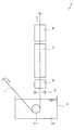
図1は,本発明の実施の形態に係る合金化溶融亜鉛系めっき鋼板の製造設備1の構成図である。図1に示すように,製造設備1は,めっき浴槽2の鉛直方向上方に,下から順に,ガスワイピングノズル5,急速加熱炉6,保熱冷却兼用炉7及び冷却炉8を配置した構成を有する。めっき浴槽2内には,めっき浴10として440〜480℃の溶融亜鉛めっき等が満たされている。製造設備1は,図1の矢印に示すように,鋼板Iをめっき浴槽2内に上方から下方に所定の傾斜角度で進入させ,めっき浴10に浸漬させた後に,めっき浴槽2内に設けたサポートロール11の案内によって,鋼板Iを鉛直方向上方(即ち,通板方向)に進行させてめっき浴10から退出させ,ガスワイピングノズル5,急速加熱炉6,保熱冷却兼用炉7及び冷却炉8を順に通板させることによって鋼板Iを合金化処理するように構成されている。
FIG. 1 is a configuration diagram of a
ガスワイピングノズル5は,めっき浴10から退出して通板する鋼板Iの両面に対向配置され,鋼板Iの両面にガスを吹付けることによって,鋼板Iの表面に付着しためっきの付着量を調整するように構成されている。
The
急速加熱炉6は,誘導加熱炉及び/又はバーナ加熱炉により構成される。本実施の形態では,急速加熱炉6は,鋼板Iを30℃以上/secの昇温速度で加熱し,鋼板Iを500℃以上の到達温度に到達させることが可能な加熱能力を備えている。
The
冷却炉8は,その炉内に,鋼板Iの両面に対向配置したノズル(図示せず)を鋼板Iの通板方向に沿って複数備え,保熱冷却兼用炉7から退出した鋼板Iに対して,これらのノズルから冷風を噴射することによって,鋼板Iを冷却するように構成されている。なお,ノズルから噴射されるのは,冷風以外にもミスト又はフォグ等であってもよい。
The cooling
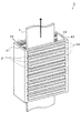
図2は,保熱冷却兼用炉7の斜視図である。図3は,保熱冷却兼用炉7の側面構成図である。
FIG. 2 is a perspective view of the heat and cooling combined
保熱冷却兼用炉7は,図2に示すように,開放した上下面を備えた直方体形状の本体20内を鋼板Iが鉛直方向上向きに通板するように構成されている。本体20内には,図3に示すように,通板する鋼板Iの両面に対向配置され,鋼板Iを両面から輻射加熱可能な保熱手段21が通板方向に沿って8対設けられている。また,本体20内には,鋼板Iの両面に対向配置され,鋼板Iの両面に冷却ガスを噴射可能な吹付ノズル22が通板方向に沿って8対設けられ,その下流側であって,本体20の上部には本体20内の雰囲気を排気する排気口43が形成されている。本実施の形態では,保熱手段21の各対と吹付ノズル22の各対が,通板方向に沿って所定間隔で交互に配置されている。また,本実施の形態では,保熱手段21として電気ヒーターを用いており,吹付ノズル22としてフラットノズルを用いている。
As shown in FIG. 2, the heat insulating and
保熱手段21は,対向配置した各対毎に,その保熱動作を個別に制御可能である。これにより,保熱手段21の各対を個別に作動させたり,停止させたりして,鋼板Iを加熱し保熱する保熱状態と,鋼板Iの加熱を停止する停止状態とを切替えることが可能である。 The heat retaining means 21 can individually control the heat retaining operation for each of the opposed pairs. Thereby, each pair of the heat retaining means 21 can be individually operated or stopped to switch between a heat retaining state in which the steel plate I is heated and retained and a stopped state in which the heating of the steel plate I is halted. Is possible.
吹付ノズル22は,その噴射口を鋼板Iの板幅方向に平行な軸を中心に回転させることによって,冷却ガスを噴射する噴射方向を調整できるように構成されている。これにより,吹付けノズル22の噴射方向を鋼板Iの面に対して垂直に(即ち,噴射方向を水平方向に)設定したり,鋼板Iの面に対して傾斜するように(即ち,噴射方向が水平方向に対して傾斜するように)設定することが可能である。吹付ノズル22は,対向配置した各対毎に,冷却ガスの噴射動作を個別に制御可能である。これにより,吹付ノズル22の各対の噴射方向を個別に設定し,さらに,各対を個別に作動させたり,停止させたりして,冷却ガスを鋼板Iに噴射する噴射状態と,吹付ノズル22の噴射を停止させた停止状態とを切替えることが可能である。
The
保熱冷却兼用炉7は,合金化する鋼板Iの鋼種,めっき付着量及び通板速度(ラインスピードとも呼ぶ)等の合金化条件に応じて,急速加熱炉6側(即ち,鋼板Iの入側)において鋼板Iを保熱する保熱領域15と,冷却炉8側(即ち,鋼板Iの出側)において鋼板Iを冷却する冷却領域16との比率を変更可能な構成を有する。保熱領域15は,保熱冷却兼用炉7の入側から通板方向に沿って連続する保熱手段21を作動させて保熱状態にすると共に,保熱状態にした保熱手段21の上流(即ち,鉛直方向下方)にある吹付ノズル22を全て停止させて停止状態にすることによって設定される。これに対して,冷却領域16は,残り全ての保熱手段21を停止させて停止状態にすると共に,残り全ての吹付ノズル22を作動させて噴射状態にすることによって設定される。
The heat-retaining and
以上の構成を有する保熱冷却兼用炉7は,保熱領域15で通板される鋼板Iを保熱温度500℃以上に保熱可能であり,且つ冷却領域16で通板される鋼板Iを5℃/sec以上の平均冷却速度で冷却可能であるように構成されている。
The combined heat and
以上のように構成された本発明の実施の形態に係る製造設備1を用いて合金化溶融亜鉛系めっき鋼板を製造する方法を図1〜図3を用いて説明する。
A method for producing an alloyed hot-dip galvanized steel sheet using the
まず,図1に示すように,鋼種Aの鋼板Iを矢印方向に通板速度Bで通板し,めっき浴槽2内のめっき浴10中に浸漬させてから,鉛直方向上方に進行させ,めっき浴10から退出させる。めっき浴10から退出させた鋼板Iを,ガスワイピングノズル5の処理領域に進入させ,鋼板Iの両面にガスを吹付け,鋼板Iの表面に付着しためっきを吹飛ばすことによって,鋼板Iのめっき付着量をCに調整する。
First, as shown in FIG. 1, a steel plate I of steel type A is passed in the direction of the arrow at a passing speed B, immersed in the
次いで,鋼板Iをガスワイピングノズル5の処理領域から退出させ,急速加熱炉6に進入させる。そして急速加熱炉6内で鋼板Iを通板させながら,鋼板Iを30℃/sec以上の昇温速度で加熱し,鋼板Iを500℃以上,好ましくは650℃以下の到達温度に到達させる。
Next, the steel plate I is withdrawn from the processing region of the
その後,急速加熱炉6において,鋼板Iが所定温度に達した後,鋼板Iを急速加熱炉6から退出させ,保熱冷却兼用炉7に進入させる。なお,保熱冷却兼用炉7は,鋼板Iの鋼種,通板速度及びめっき付着量等の製造条件に基づいて,保熱領域15及び冷却領域16の比率が最適となるように予め設定しておく。例えば,鋼板Iが鋼種A,通板速度がB,めっき付着量がCという製造条件で溶融亜鉛系めっき鋼板を製造する場合には,図3に示すように,保熱冷却兼用炉7の下側で鋼板Iを保熱し,保熱冷却兼用炉7の上側で鋼板Iを冷却するのが適切である場合について詳述する。
Thereafter, in the
この場合には,保熱冷却兼用炉7内の下側の保熱領域15にある4対の保熱手段21が保熱状態(図3中では,斜線により保熱状態を示した)に設定される一方で,上側の冷却領域16にある4対の保熱手段21が停止状態に設定される。そして,保熱冷却兼用炉7内の上側の冷却領域16にある3対の吹付ノズル22が噴射状態(図3中では,点線矢印により噴射状態を示した)に設定される一方で,下側の保熱領域15にある3対の吹付ノズル22が停止状態に設定される。
In this case, the four pairs of heat retaining means 21 in the lower
上述したように保熱領域15及び冷却領域16の比率を設定した保熱冷却兼用炉7内で鋼板Iを通板速度Bで通板させながら,鋼板Iが保熱領域15を進行する間,4対の保熱手段21を用いて鋼板Iを輻射加熱し,保熱温度500℃以上かつ650℃以下に保熱する。次いで,鋼板Iを保熱領域15から冷却領域16に進行させ,鋼板Iが冷却領域16を進行する間,通板速度Bで通板させながら,5対の吹付ノズル22から冷却ガスを鋼板Iに向けて噴射し,5℃/sec以上の平均冷却速度で冷却する。
While passing the steel plate I at the plate speed B in the heat insulating and
そして,保熱冷却兼用炉7から退出させ,冷却炉8に進入させる。冷却炉8内で鋼板Iを通板速度Bで通板させながら,ノズル(図示せず)を用いて冷風,ミスト又はフォグを噴射し,鋼板Iを冷却する。以上の一連の合金化処理によって,鋼種Aの鋼板Iから最適な合金層を有する合金化溶融亜鉛系めっき鋼板が製造される。
Then, it exits from the heat insulation and cooling combined
なお,図3に示すように,保熱冷却兼用炉7が保熱領域15及び冷却領域16の両方を有するように設定する場合には,冷却領域16を構成する吹付ノズル22の全ての対のうちで,通板方向において最も保熱領域15側にある(即ち,保熱領域15及び冷却領域16の境界にある)吹付ノズル22の対を,その噴射方向が鋼板Iの面に対して垂直になるように(即ち,水平方向に平行になるように)設定する。これにより,保熱領域15及び冷却領域16の境界では,吹付ノズル22から噴射された冷却ガスは,エアカーテンのように保熱領域15及び冷却領域16の間に気体の壁を形成し,保熱領域15側の加熱された雰囲気が冷却領域16側に進入すること防止する。一方,冷却領域16を構成する残りの吹付ノズル22の対は,その噴射方向が鋼板Iの面に対して通板方向(即ち,鉛直方向)を向くように(即ち,水平方向に対して上向きに傾斜するように)設定する。これにより,冷却領域16の雰囲気(冷却ガスを含む)が鋼板Iの通板方向に沿って進行し,保熱冷却兼用炉7及び冷却炉8の排気口43の間から外部に退出する流れが形成され,内部の圧力は一定に保たれる。なお,排気口43は,所定の内部圧力に保つために,少なくとも保熱冷却兼用炉7の上部又は保熱領域15と冷却領域16との境界になりえる箇所に形成してもよい。
As shown in FIG. 3, when the heat-retaining and
上記では,保熱冷却兼用炉7の保熱領域15及び冷却領域16の配置について,鋼板Iを保熱後に冷却する場合について述べてきたが,鋼種によっては,加熱の後に直ちに冷却し,その後に保熱を行うように設定し,δ1相主体の亜鉛めっきを形成することがよい場合がある(図示せず)。かかる場合,例えば,保熱冷却兼用炉7の下流側は吹付ノズル22にて鋼板Iの冷却を行い,上流側は保熱手段21によって保熱手段21によって鋼板Iの保熱を行う。
In the above description, the arrangement of the
上記では,保熱冷却兼用炉7が,保熱冷却兼用炉7が保熱領域15及び冷却領域16の両方を有する場合について説明したが,保熱領域15及び冷却領域16のいずれか一方だけを有するように設定してもよい。図4は,その一例として,鋼種D,通板速度E,及びめっき付着量Fという製造条件に基づいて,保熱領域15だけを有するように設定された保熱冷却兼用炉7の側面構成図である。この場合には,図4に示すように,保熱冷却兼用炉7の保熱手段21が全て保熱状態に設定されると共に,吹付ノズル22が全て停止状態に設定されている。
In the above description, the case where the heat retention / cooling combined
以上の実施の形態によれば,鋼板Iから合金化溶融亜鉛系めっき鋼板を製造する際に,鋼板Iの鋼種,通板速度及びめっき付着量等の製造条件に基づいて,保熱冷却兼用炉7内での保熱領域15及び冷却領域16の比率を変更し,合金化処理における保熱過程及び冷却過程を製造条件に応じて最適に設定するようにしたので,未合金化部分を発生させずにζ相及びΓ相を低減させ,δ1相を主体とする高品質の合金化溶融亜鉛系めっき鋼板を適切に製造することができる。さらに,保熱冷却兼用炉7内に通板方向に沿って交互に配置した保熱手段21及び吹付ノズル22を個別に制御し,保熱冷却兼用炉7内での保熱領域15及び冷却領域16の比率を切替えるようにしたことによって,切替えの応答性が高くなり,各製造条件に応じた保熱領域15及び冷却領域16の比率の切替えを従来よりも短時間で完了し,合金化溶融亜鉛系めっき鋼板の製造を即座に開始できるため,運用が非常に容易化される。
According to the above embodiment, when producing an alloyed hot dip galvanized steel sheet from the steel sheet I, the heat and cooling combined use furnace is based on the production conditions such as the steel type of the steel sheet I, the plate passing speed, and the coating amount. 7, the ratio of the
さらに,冷却領域16を構成する吹付ノズル22の対のうちで,通板方向において最も保熱領域15側にある吹付ノズル22の対の冷却ガスの噴射方向が,鋼板Iの面に対して垂直になるように設定したことによって,保熱冷却兼用炉7が保熱領域15及び冷却領域16の両方を有する場合に,最も保熱領域15側にある吹付ノズル22の対から噴射する冷却ガスが保熱領域15及び冷却領域16の間にエアカーテンと同じ原理で気体の流れの壁を形成し,保熱領域15及び冷却領域16の温度干渉を低減し,各々の保熱効果及び冷却効果を高めることが可能になる。さらに,冷却領域16において,その雰囲気(冷却ガスを含む)が鋼板Iの通板方向に沿って進行し,保熱冷却兼用炉7及び冷却炉8の間から外部に退出する流れを形成するようにしたことによって,鋼板Iを冷却し温度が上昇した冷却ガスを退出させ,常に低温の冷却ガスで鋼板Iを冷却することが可能になる。
Further, among the pair of
保熱冷却兼用炉7が,鋼板Iを熱風加熱する保熱手段40を有するようにしてもよい。図5は,このような構成を採用した本発明の第2の実施の形態に係る合金化溶融亜鉛系めっき鋼板の製造設備1が備える保熱冷却兼用炉7の全体図である。
The heat-retaining and
図5に示すように,第2の実施の形態では,保熱冷却兼用炉7の本体20内の入側に,通板する鋼板Iの両面に対向配置され,本体20内に熱風を送込むことによって,鋼板Iを両面から熱風加熱可能な送風装置41が1対設けられている。この1対の送風装置41の下流(即ち,鉛直方向上方)には,第1の実施の形態と同様に,鋼板Iの両面に対向配置され,鋼板Iの両面に冷却ガスを噴射可能な吹付ノズル22が通板方向に沿って8対設けられ,その下流側には排気口43が配置されている。また,本体20内には,鋼板Iの両面に対向配置され,本体20内の雰囲気を排気可能な排気装置42が通板方向に沿って4対設けられている。第2の実施の形態では,2対の吹付ノズル22と,1対の排気装置42が通板方向に沿って所定間隔で交互に配置されている。
As shown in FIG. 5, in the second embodiment, hot air is sent into the
保熱冷却兼用炉7の保熱手段40は,上述した1対の送風装置41と,4対の排気装置42を有する。第2の実施の形態では,排気装置42として開閉可能な装置を用いている。保熱手段40の送風装置41及び排気装置42は,対向配置した各対毎に,その動作を個別に制御可能である。例えば,保熱冷却兼用炉7が保熱領域15を有するように設定する場合には,送風装置41を作動させて送風状態に設定し,保熱領域15を有さないように設定する場合には,送風装置41を停止させて停止状態に設定することができる。また,保熱冷却兼用炉7が保熱領域15を有するように設定する場合には,排気装置42の各対を個別に開閉し,本体20内の雰囲気を排気する排気状態と,排気を行わない閉鎖状態とを切替えることが可能である。
The heat retaining means 40 of the heat retaining and cooling combined
第2の実施の形態では,保熱冷却兼用炉7が保熱領域15を有するように設定する場合には,保熱領域15の最も下流(即ち,鉛直方向上方)にある排気装置42の対を開放して排気状態に設定し,残りの排気装置42の対を全て閉鎖して閉鎖状態に設定する。これにより,図5に一点鎖線で示すように,送風状態の送風装置41から送風された熱風は,鋼板Iを保熱しながら,本体20内の保熱領域15を通板方向に沿って進行し,排気状態の排気装置42から退出するように流れる。
In the second embodiment, when the heat-retaining and cooling combined
以上の第2の実施の形態によれば,保熱冷却兼用炉7内の冷却領域16を通板する鋼板Iを冷却ガスで冷却することに加え,保熱領域15を通板する鋼板Iを熱風で保熱するようにしたことによって,保熱領域15から冷却領域16の比率を切替える際に,本体20内の雰囲気を即座に入替ることができ,切替えの応答性がさらに高くなる。これにより,各製造条件に応じた保熱領域15及び冷却領域16の比率の切替えがさらに短時間で完了し,運用がさらに容易化される。
According to the second embodiment described above, in addition to cooling the steel plate I passing through the
さらに,保熱手段40の排気装置42を保熱領域15と冷却領域16の境界になり得る箇所に配設したことによって,保熱領域15側の加熱された雰囲気を冷却領域16に進行させずに外部に排気することができ,保熱領域15及び冷却領域16の温度干渉を低減し,各々の保熱効果及び冷却効果を高めることが可能になる。特に,第1の実施の形態で説明したように,保熱領域15と冷却領域16の境界にある吹付ノズル22から鋼板Iの面に垂直に冷却ガスを噴射し,エアカーテンとして機能させる場合には,保熱領域15及び冷却領域16の温度干渉をさらに低減させ,各々の保熱効果及び冷却効果を一層,高めることができる。なお,第2の実施形態は,第1の実施形態で得られるその他の効果も同様に得られる。図5では,送風装置41は,本体の最も上流側(即ち,鉛直方向下方)に設定され,保熱の後に冷却を行う配置になり,鋼種ごとに配置を変更することはできないが,送風装置41を本体20の中央部に追加,又は送風装置41の設置位置を本体20の中央部に変更することによって,冷却の後に保熱を行う配置にすることも可能である。
Further, by arranging the
以上,添付図面を参照しながら本発明の好適な実施形態について説明したが,本発明は係る例に限定されない。当業者であれば,特許請求の範囲に記載された技術的思想の範疇内において,各種の変更例又は修正例に想到し得ることは明らかであり,それらについても当然に本発明の技術的範囲に属するものと了解される。 As mentioned above, although preferred embodiment of this invention was described referring an accompanying drawing, this invention is not limited to the example which concerns. It is obvious for those skilled in the art that various changes or modifications can be conceived within the scope of the technical idea described in the claims. It is understood that it belongs to.
上述した実施形態においては,保熱冷却兼用炉7が,鋼板Iの両面に対向配置された8対の保熱手段21及び吹付ノズル22を有する場合について説明したが,保熱手段21及び吹付ノズル22は任意の個数であってもよい。
In the above-described embodiment, the case where the heat-retaining and
上述した実施形態においては,保熱冷却兼用炉7内において,1対の吹付ノズル22と1対の保熱手段21が通板方向に沿って交互に配置されている場合,並びに2対の吹付ノズル22と1対の保熱手段21が通板方向に沿って交互に配置されている場合について説明したが,任意の個数の対の保熱手段21と任意の個数の対の吹付ノズル22を通板方向に沿って交互に配置するようにしてもよい。また,その際に,通板方向に沿って連続して配置した吹付けノズル22の対をまとめて制御するようにしてもよい。同様に,通板方向に沿って連続して配置した保熱手段21の対をまとめて制御するようにしてもよい。
In the above-described embodiment, when the pair of
上述した実施形態においては,保熱冷却兼用炉7を,図3に示すように,鋼種がA,通板速度がB及びめっき付着量がCである製造条件に基づいて保熱領域15及び冷却領域16の両方を有するように設定した場合と,図4に示すように,鋼種がD,通板速度がE及びめっき付着量がFである製造条件に基づいて保熱冷却兼用炉7が保熱領域15だけを有するように設定した場合について説明したが,保熱冷却兼用炉7を,(1)保熱領域15だけを有する設定,(2)冷却領域16だけを有する設定,及び(3)保熱領域15及び冷却領域16の両方を有する設定,の3つの設定(1)〜(3)の間で任意に設定を変更してもよい。また,その際に,保熱領域15及び冷却領域16の比率,及び保熱領域15と冷却領域16の配置を任意に設定してもよい。
In the above-described embodiment, as shown in FIG. 3, the heat-retaining and
上述した実施形態においては,製造設備1は,めっき浴槽2の上方に,下から順に,ガスワイピングノズル5,急速加熱炉6,保熱冷却兼用炉7及び冷却炉8が配置されている場合について説明したが,製造設備1その他の構成であってもよい。特に,急速加熱炉6と保熱冷却兼用炉7との間に,鋼板Iを500℃以上かつ650℃以下に保熱する保熱専用炉を配設し,保熱冷却兼用炉7以外でも鋼板Iの保熱を行うようにしてもよい。
In the embodiment described above, the
上述した実施形態においては,保熱冷却兼用炉7の保熱手段40の送風装置41が1対の場合について説明したが,保熱冷却兼用炉7に任意の数の送風装置41を設けてもよい。また,送風装置41の配置構成は任意であってもよい。例えば,図5に示す保熱冷却兼用炉7内の下から2番目に配置された吹付ノズル22の対の上に,図5に示す送風装置41とは別の1対の送風装置41を対向配置してもよい。保熱冷却兼用炉7の長さが長い場合には,このように別の送風装置41を配置することにより,冷却帯を保熱帯に切替える時間を短縮し,応答性を上げることができる。
In the above-described embodiment, the case where the pair of the
上述した実施形態においては,保熱冷却兼用炉7の保熱手段40の送風装置41が本体20内に熱風を送込んで鋼板Iを熱風加熱する場合について説明したが,送風装置41が冷却領域16内にある場合には,送風装置41から本体20内に冷風を送込んで鋼板Iを冷風冷却するようにしてもよい。
In the above-described embodiment, the case where the
本発明の実施例を比較例との比較で説明する。 Examples of the present invention will be described in comparison with comparative examples.
まず,保熱冷却兼用炉によって,鋼板の保熱後に冷却を行う場合について述べる。本発明の製造設備及び従来式の製造設備を用いて,表1に示す各成分構成の鋼種の試験材から,各種の製造条件の下で合金化溶融亜鉛系めっき鋼板を製造した結果を表2に示す。なお,本発明の製造設備が有する保熱冷却兼用炉の通板方向の長さを25mとした。従来式の製造設備については,固定型の保熱炉の通板方向の長さを14.2m,固定型の冷却炉の通板方向の長さを10.8mとした。また,めっき浴中のAl濃度は,本発明の製造設備及び従来式の製造設備の両方で,0.134質量%とした。 First, the case where cooling is performed after heat insulation of the steel sheet by a heat insulation and cooling furnace will be described. Table 2 shows the results of producing alloyed hot-dip galvanized steel sheets under various production conditions from the test materials of the steel types having the components shown in Table 1 using the production equipment of the present invention and the conventional production equipment. Shown in In addition, the length of the plate | board direction of the heat-retaining-cooling combined use furnace which the manufacturing equipment of this invention has was 25 m. For the conventional manufacturing equipment, the length of the fixed heat-retaining furnace in the plate passing direction was 14.2 m, and the length of the fixed cooling furnace in the plate passing direction was 10.8 m. In addition, the Al concentration in the plating bath was set to 0.134% by mass in both the manufacturing equipment of the present invention and the conventional manufacturing equipment.

表2における合金層評価では,製造した合金化溶融亜鉛系めっき鋼板の合金層が,δ1相を主体とする最適な合金層になっている場合には○印で示し,ζ相及びΓ相が過多である場合には△印で示し,合金化不良の状態になっている場合には×印で示した。 In the evaluation of the alloy layer in Table 2, when the alloy layer of the manufactured galvannealed steel sheet is an optimum alloy layer mainly composed of δ 1 phase, it is indicated by ○, and the ζ phase and Γ phase When the amount is excessive, it is indicated by Δ, and when it is in a state of poor alloying, it is indicated by ×.
まず,合金化溶融亜鉛系めっき鋼板を製造する際の条件のうちで,めっき付着量が変化する場合について考察する。表2に示すように,試験材1を用いた本発明による実施例No.1〜3では,めっき付着量が各々32〜62(g/m2)と変化した場合に,通板速度142(m/min)及び急速加熱炉の昇温速度を36.4(℃/sec)を変更せずに,保熱冷却兼用炉の保熱領域及び冷却領域の比率を変更することによって,試験材1を最適に保熱し,いずれの場合にも通板速度を変化させることなく最適な合金層を有する合金化溶融亜鉛系めっき鋼板を製造することができ,めっき付着量の変化においても,焼鈍炉等のライン内の他の設備に影響を与えることなく対応が可能となった。
First, let us consider the case where the amount of plating adhesion changes among the conditions for producing galvannealed steel sheets. As shown in Table 2, in Examples Nos. 1 to 3 using the
これに対して,試験材1を用いた従来技術による比較例No.6〜8では,めっき付着量が31,46,61(g/m2)と変化した場合に,通板速度を155,142,122(m/min)と各々変更することによって,試験材1に対する最適な保熱時間の確保を試みたが,比較例No.6では,本設備の通板速度の上限155(m/min)に達してしまい,試験材1に対する最適な保熱時間4(sec)を確保できずに,製造した合金化溶融亜鉛系めっき鋼板の合金層が,合金化不良を生じてしまっている。さらに,比較例No.8では,試験材1に対する最適な保熱時間7(sec)を確保できて最適な合金層を有する合金化溶融亜鉛系めっき鋼板を製造できたが,通板速度が122(m/min)と非常に遅いため,生産効率が非常に低下してしまった。このように,めっき付着量の変化において,通板速度のみによる対応では,設備上の通板速度の上限のために対応が不可能になったり,生産効率に大きく影響を与えてしまう。
On the other hand, in comparative examples No. 6 to 8 according to the prior art using the
また,試験材1を用いた従来技術による比較例No.9,10では,めっき付着量が61,31(g/m2)と各々変化した場合に,保熱時間を変更せずに,急速加熱炉の昇温速度を51.0,23.7(℃/sec)と各々変更することによって,試験材1を最適に保熱しようとした。しかしながら,比較例No.9では,昇温速度が51.0(℃/sec)と高すぎるために,合金化不良が発生してしまった。また,比較例No.10では,昇温速度が23.7(℃/sec)と低すぎるために,製造した合金化溶融亜鉛系めっき鋼板の合金層は,ζ相及びΓ相が過多な状態になってしまった。
Further, in Comparative Examples Nos. 9 and 10 using the
また,合金化溶融亜鉛系めっき鋼板を製造する際の条件のうちで,鋼種が変化する場合について考察する。表2に示すように,本発明による実施例No.4では,鋼種を試験材1から試験材2に代えて合金化溶融亜鉛系めっき鋼板を製造している。この場合にも,保熱冷却兼用炉の保熱領域及び冷却領域の比率を調整することによって,試験材2を最適に保熱し,最適な合金層を有する合金化溶融亜鉛系めっき鋼板を製造することができた。
In addition, we consider the case where the steel grade changes among the conditions when manufacturing galvannealed steel sheets. As shown in Table 2, in Example No. 4 according to the present invention, the steel type is changed from the
これに対して,従来技術による比較例No.11では,鋼種を試験材1から試験材2に代えて合金化溶融亜鉛系めっき鋼板を製造しているが,試験材2を最適に保熱することができず,製造した合金化溶融亜鉛系めっき鋼板の合金層は,Γ相が過多な状態になってしまった。
On the other hand, in Comparative Example No. 11 according to the prior art, the alloyed hot dip galvanized steel sheet is manufactured by changing the steel type from the
また,合金化溶融亜鉛系めっき鋼板を製造する際の条件のうちで,通板速度が変化する場合について考察する。表2に示すように,試験材2を用いた本発明による実施例No.5では,同じ試験材2を用いた実施例No.4の通板速度142(m/min)と比較して,115(m/min)と低くなっている。この場合にも,保熱冷却兼用炉の保熱領域及び冷却領域の比率を調整することによって,試験材2を最適に保熱し,最適な合金層を有する合金化溶融亜鉛系めっき鋼板を製造することができた。
In addition, we consider the case where the plate feed speed changes among the conditions for producing galvannealed steel sheets. As shown in Table 2, in Example No. 5 using the
次に,保熱冷却兼用炉によって,鋼板の冷却後に保熱を行う場合について述べる。本発明の製造設備及び従来式の製造設備を用いて,表3に示す成分構成の鋼種の試験材から,各種の製造条件の下で合金化溶融亜鉛系めっき鋼板を製造した結果を表4に示す。なお,本発明の製造設備が有する保熱冷却兼用炉の通板方向の長さを25mとした。従来式の製造設備については,固定型の保熱炉の通板方向の長さを14.2m,固定型の冷却炉の通板方向の長さを10.8mとした。また,めっき浴中のAl濃度は,本発明の製造設備及び従来式の製造設備の両方で,0.134質量%とした。 Next, the case where heat insulation is performed after the steel plate is cooled by a heat insulation and cooling furnace will be described. Table 4 shows the results of producing alloyed hot-dip galvanized steel sheets under various production conditions from test materials of the steel types having the composition shown in Table 3 using the production equipment of the present invention and conventional production equipment. Show. In addition, the length of the plate | board direction of the heat-retaining-cooling combined use furnace which the manufacturing equipment of this invention has was 25 m. For the conventional manufacturing equipment, the length of the fixed heat-retaining furnace in the plate passing direction was 14.2 m, and the length of the fixed cooling furnace in the plate passing direction was 10.8 m. In addition, the Al concentration in the plating bath was set to 0.134% by mass in both the manufacturing equipment of the present invention and the conventional manufacturing equipment.
表4における合金層評価では,製造した合金化溶融亜鉛系めっき鋼板の合金層が,δ1相を主体とする最適な合金層になっている場合には○印で示し,ζ相及びΓ相が過多である場合には△印で示し,合金化不良の状態になっている場合には×印で示した。 In the evaluation of the alloy layer in Table 4, when the alloy layer of the manufactured alloyed hot dip galvanized steel sheet is an optimum alloy layer mainly composed of δ 1 phase, it is indicated by ○, and ζ phase and Γ phase When the amount is excessive, it is indicated by Δ, and when it is in a state of poor alloying, it is indicated by ×.
鋼種によっては,最初の加熱にて適量のFe分を合金層中に噴出させた後に,直ちに冷却して過剰なFe分の噴出による外観不良を防止し,適温で保持することでδ1相主体の合金層を形成することが良い場合がある。表4に示すように,試験材3を用いた本発明による実施例No.12と13では,本発明の製造設備を使用すれば,先の実施例と同様,通板速度をそれぞれ140(m/min)と105(m/min)に変化させても,保熱冷却兼用炉の保熱領域及び冷却領域の比率を調整することによって,急速加熱炉の出側温度及び保熱冷却兼用炉における冷却後の保持温度を常に最適に維持できた。これによって,最適な合金層を有する合金化溶融亜鉛系めっき鋼板を製造することができた。 The type of steel, a suitable amount of the Fe component after jetted alloy layer, immediately cooled to prevent appearance failure by ejecting the excessive Fe content, [delta] 1 main phase by holding at an appropriate temperature in the first heating It may be good to form an alloy layer. As shown in Table 4, Example No. according to the present invention using the test material 3 was used. In Nos. 12 and 13, if the manufacturing equipment of the present invention is used, as in the previous embodiment, even if the plate passing speed is changed to 140 (m / min) and 105 (m / min), respectively, the heat and cooling function is used. By adjusting the ratio of the heat retention area and cooling area of the furnace, the exit temperature of the rapid heating furnace and the retention temperature after cooling in the combined heat and cooling furnace could always be maintained optimally. As a result, an alloyed hot-dip galvanized steel sheet with an optimal alloy layer could be manufactured.
これに対して,試験材3を用いた従来技術による比較例No.14では,No.12と13と同じ急速加熱炉の出側温度である553℃としても,保熱冷却兼用炉において,鋼板の冷却を行わず553℃の保持温度で保持してしまうと,過剰なFe分の噴出により,合金化溶融亜鉛系めっき鋼板の合金層は外観不良となった。 In contrast, Comparative Example No. 1 according to the prior art using the test material 3 was used. 14, no. Even if the outlet temperature of the same rapid heating furnace as 12 and 13 is 553 ° C, if the steel plate is not cooled in the combined heat and cooling furnace and kept at the holding temperature of 553 ° C, the excess Fe content is ejected. As a result, the alloy layer of the galvannealed steel sheet became poor in appearance.
また,試験材3を用いた従来技術による比較例No.15では,過剰なFe分の噴出を抑制するために,急速加熱炉の出側温度を530℃に下げると,Fe分の拡散量が不十分であったため,合金化溶融亜鉛系めっき鋼板の合金層は合金化不良となった。 In addition, Comparative Example No. according to the prior art using the test material 3 was used. In No. 15, when the outlet temperature of the rapid heating furnace was lowered to 530 ° C. in order to suppress the ejection of excessive Fe content, the amount of diffusion of Fe content was insufficient. The layer was poorly alloyed.
また,試験材3を用いた従来技術による比較例No.16と17には,急速加熱炉の出側に固定式の冷却炉を配置した場合の結果を示す。鋼板の冷却後の保持温度を最適に維持しようとすると,通板速度の調整が必要となり,No.16と17の通板速度をそれぞれ140(m/min)と105(m/min)とした。かかる場合,No.16では最適な保持温度で保持でき,最適な合金層を有する合金化溶融亜鉛系めっき鋼板を製造することができた。しかしながら,No.17では,保持温度が不足してFe分の拡散量が不十分であったため,合金化溶融亜鉛系めっき鋼板の合金層は合金化不良となった。 In addition, Comparative Example No. according to the prior art using the test material 3 was used. 16 and 17 show the results when a fixed cooling furnace is arranged on the exit side of the rapid heating furnace. In order to maintain the holding temperature after cooling the steel plate optimally, it is necessary to adjust the feeding speed. The plate passing speeds of 16 and 17 were 140 (m / min) and 105 (m / min), respectively. In such a case, no. No. 16 could be maintained at an optimal holding temperature, and an alloyed hot-dip galvanized steel sheet having an optimal alloy layer could be produced. However, no. In No. 17, since the holding temperature was insufficient and the diffusion amount of Fe was insufficient, the alloy layer of the galvannealed steel sheet was inferior in alloying.
本発明は,合金化溶融亜鉛系めっき鋼板を製造する溶融亜鉛系めっき鋼板の製造設備に特に有用である。 INDUSTRIAL APPLICABILITY The present invention is particularly useful for a production facility for hot dip galvanized steel sheets for producing galvannealed steel sheets.
1 合金化溶融亜鉛系めっき鋼板の製造設備
2 めっき浴槽
5 ガスワイピングノズル
6 急速加熱炉
7 保熱冷却兼用炉
8 冷却炉
10 めっき浴
11 サポートロール
15 保熱領域
16 冷却領域
20 本体
21,40 保熱手段
22 吹付ノズル
41 送風装置
42 排気装置
43 排気口
I 鋼板
DESCRIPTION OF
Claims (7)
めっき浴槽の上方に設置され,30℃/sec以上の昇温速度及び500℃以上の到達温度の加熱能力を有する急速加熱炉と,
前記急速加熱炉の上方に設置され,前記急速加熱炉を退出した鋼板に対し保熱及び冷却の少なくともいずれか一方を行う保熱冷却兼用炉とを有し,
前記保熱冷却兼用炉は,鋼板を500℃以上かつ650℃以下に保熱する保熱手段を有する保熱領域及び鋼板を5℃/sec以上の平均冷却速度で冷却する冷却手段を有する冷却領域から構成されており,炉内における両領域の長さの比率を任意に設定可能であり,かつ,前記保熱領域と冷却領域の配置構成を任意に設定可能であり,
前記保熱冷却兼用炉内においては,通板する鋼板の両面に対向配置された,少なくとも1対の前記保熱手段と,通板する鋼板の両面に対向配置された,少なくとも1対の前記冷却手段とが,鋼板の通板方向に沿って交互に配置され,
前記冷却手段は,吹付ノズルから冷却媒体を鋼板に噴射し,
前記吹付ノズルは,その噴射口が鋼板の板幅方向に平行な軸を中心に回転可能に構成され,
前記保熱領域及び前記冷却領域の境界にある前記吹付ノズルが冷却ガスを鋼板に垂直に噴射し,気体の流れの壁を形成可能であることを特徴とする,合金化溶融亜鉛系めっき鋼板の製造設備。 In a manufacturing facility for alloyed hot-dip galvanized steel sheets, which are immersed in a plating bath and then alloyed,
A rapid heating furnace installed above the plating bath, having a heating rate of 30 ° C./sec or more and a heating capability of an ultimate temperature of 500 ° C. or more;
A heat retaining and cooling combined furnace that is installed above the rapid heating furnace and performs at least one of heat retaining and cooling on the steel sheet exiting the rapid heating furnace;
The heat-retaining and cooling furnace includes a heat-retaining region having a heat-retaining means for keeping the steel plate at 500 ° C. or more and 650 ° C. or less, and a cooling region having a cooling means for cooling the steel plate at an average cooling rate of 5 ° C./sec or more. are composed of a arbitrarily set the ratio of the length of the two regions in the furnace, and, Ri arbitrarily settable der an arrangement of the heat retaining region and the cooling region,
In the heat insulation and cooling combined use furnace, at least one pair of the heat insulation means disposed opposite to both surfaces of the steel plate to be passed through and at least one pair of the cooling disposed opposite to both surfaces of the steel plate to be passed through. Means are alternately arranged along the plate passing direction of the steel plate,
The cooling means sprays a cooling medium from the spray nozzle onto the steel plate,
The spray nozzle is configured such that its injection port is rotatable about an axis parallel to the plate width direction of the steel plate,
In the alloyed hot-dip galvanized steel sheet, the spray nozzle at the boundary between the heat retaining area and the cooling area can inject a cooling gas perpendicularly to the steel sheet to form a gas flow wall . production equipment.
Using any of the manufacturing facilities of the claims 1 to 6, was dipped steel sheet in a plating bath, a manufacturing method of alloyed hot-dip galvanized steel sheet to an alloying treatment.
Priority Applications (1)
| Application Number | Priority Date | Filing Date | Title |
|---|---|---|---|
| JP2007228474A JP5169080B2 (en) | 2006-10-13 | 2007-09-04 | Production equipment and production method of alloyed hot dip galvanized steel sheet |
Applications Claiming Priority (3)
| Application Number | Priority Date | Filing Date | Title |
|---|---|---|---|
| JP2006280593 | 2006-10-13 | ||
| JP2006280593 | 2006-10-13 | ||
| JP2007228474A JP5169080B2 (en) | 2006-10-13 | 2007-09-04 | Production equipment and production method of alloyed hot dip galvanized steel sheet |
Publications (2)
| Publication Number | Publication Date |
|---|---|
| JP2008115462A JP2008115462A (en) | 2008-05-22 |
| JP5169080B2 true JP5169080B2 (en) | 2013-03-27 |
Family
ID=39501648
Family Applications (1)
| Application Number | Title | Priority Date | Filing Date |
|---|---|---|---|
| JP2007228474A Active JP5169080B2 (en) | 2006-10-13 | 2007-09-04 | Production equipment and production method of alloyed hot dip galvanized steel sheet |
Country Status (1)
| Country | Link |
|---|---|
| JP (1) | JP5169080B2 (en) |
Families Citing this family (3)
| Publication number | Priority date | Publication date | Assignee | Title |
|---|---|---|---|---|
| MX2017005114A (en) * | 2014-10-24 | 2017-07-14 | Nippon Steel & Sumitomo Metal Corp | Cooling device for hot-dip plated steel sheet. |
| KR101639904B1 (en) * | 2014-12-19 | 2016-07-15 | 주식회사 포스코 | Apparatus for cooling of coated strip |
| CN107447099A (en) * | 2016-05-31 | 2017-12-08 | 宝钢工业炉工程技术有限公司 | Silicon strip steel heat treatment stove controls cooling section hot blast cooling device |
Family Cites Families (10)
| Publication number | Priority date | Publication date | Assignee | Title |
|---|---|---|---|---|
| JPS5838492B2 (en) * | 1979-01-22 | 1983-08-23 | 新日本製鐵株式会社 | Continuous annealing equipment for surface treatment original plates |
| JPS63121644A (en) * | 1986-11-10 | 1988-05-25 | Kawasaki Steel Corp | Heating furnace |
| JPH01283352A (en) * | 1988-05-10 | 1989-11-14 | Kawasaki Steel Corp | Galvanealing furnace |
| JPH07116580B2 (en) * | 1988-10-28 | 1995-12-13 | 川崎製鉄株式会社 | Alloying furnace with holding zone with cooling function |
| JP2970920B2 (en) * | 1989-01-31 | 1999-11-02 | 川崎製鉄株式会社 | Alloying furnace and operating method thereof |
| JP2848074B2 (en) * | 1992-01-06 | 1999-01-20 | 日本鋼管株式会社 | Galvanizing steel strip alloying equipment |
| JPH05247619A (en) * | 1992-03-03 | 1993-09-24 | Nippon Steel Corp | Vertical type galvannealing furnace for manufacturing galvannealed steel sheet |
| JPH10265924A (en) * | 1997-03-26 | 1998-10-06 | Kawasaki Steel Corp | Production of galvannealed steel sheet excellent in plating adhesion |
| JP3603534B2 (en) * | 1997-04-25 | 2004-12-22 | 住友金属工業株式会社 | Black spot flaw prevention device for hot-dip galvanized steel sheet |
| JPH11269625A (en) * | 1998-03-25 | 1999-10-05 | Sumitomo Metal Ind Ltd | Hot dip galvannealed steel sheet and its production |
-
2007
- 2007-09-04 JP JP2007228474A patent/JP5169080B2/en active Active
Also Published As
| Publication number | Publication date |
|---|---|
| JP2008115462A (en) | 2008-05-22 |
Similar Documents
| Publication | Publication Date | Title |
|---|---|---|
| KR101178614B1 (en) | Apparatus and process for producing steel sheet plated by hot dipping with alloyed zinc | |
| EP2116313B1 (en) | Device and method for cooling hot-rolled steel strip | |
| US8202471B2 (en) | Furnace configured for use in both the galvannealing and galvanizing of a metal strip | |
| JP5169080B2 (en) | Production equipment and production method of alloyed hot dip galvanized steel sheet | |
| JPH0681093A (en) | Hot dip metal coating equipment for strip | |
| JP3617473B2 (en) | Method for producing hot dip galvanized steel sheet | |
| KR101048167B1 (en) | Continuous hot dip plating device that provides excellent surface quality and manufacturing method using the same | |
| JP5444729B2 (en) | Method for producing hot dip galvanized steel sheet and continuous hot dip galvanizing apparatus | |
| US5628842A (en) | Method and apparatus for continuous treatment of a strip of hot dip galvanized steel | |
| KR101353547B1 (en) | Cooling device of continuous galvanizing line | |
| JPS6229492B2 (en) | ||
| KR101518572B1 (en) | Plating strip manufacturing apparatus | |
| JP2005113244A (en) | Facility for manufacturing galvannealed steel sheet and method for operating the same | |
| JP6784625B2 (en) | Continuous annealing furnace and method of annealing steel sheets | |
| JP4941477B2 (en) | Alloying furnace for hot dip galvanizing | |
| JPH02163358A (en) | Production of zero spangle steel sheet | |
| KR101505271B1 (en) | Gas wiping apparatus and method of manufacturing galvannealed steel sheet using the same | |
| KR800000533B1 (en) | Continuous plating apparatus for steel strip | |
| JP4363189B2 (en) | Alloying furnace for hot dip galvanizing | |
| JP2002275544A (en) | Method and equipment for continuously cooling steel strip | |
| JP2005194588A (en) | Alloying furnace for hot dip galvanizing |
Legal Events
| Date | Code | Title | Description |
|---|---|---|---|
| A621 | Written request for application examination |
Free format text: JAPANESE INTERMEDIATE CODE: A621 Effective date: 20090916 |
|
| A977 | Report on retrieval |
Free format text: JAPANESE INTERMEDIATE CODE: A971007 Effective date: 20100402 |
|
| A131 | Notification of reasons for refusal |
Free format text: JAPANESE INTERMEDIATE CODE: A131 Effective date: 20120911 |
|
| A521 | Written amendment |
Free format text: JAPANESE INTERMEDIATE CODE: A523 Effective date: 20121106 |
|
| TRDD | Decision of grant or rejection written | ||
| A01 | Written decision to grant a patent or to grant a registration (utility model) |
Free format text: JAPANESE INTERMEDIATE CODE: A01 Effective date: 20121204 |
|
| A61 | First payment of annual fees (during grant procedure) |
Free format text: JAPANESE INTERMEDIATE CODE: A61 Effective date: 20121217 |
|
| R151 | Written notification of patent or utility model registration |
Ref document number: 5169080 Country of ref document: JP Free format text: JAPANESE INTERMEDIATE CODE: R151 |
|
| FPAY | Renewal fee payment (event date is renewal date of database) |
Free format text: PAYMENT UNTIL: 20160111 Year of fee payment: 3 |
|
| S533 | Written request for registration of change of name |
Free format text: JAPANESE INTERMEDIATE CODE: R313533 |
|
| R350 | Written notification of registration of transfer |
Free format text: JAPANESE INTERMEDIATE CODE: R350 |