JP5168564B2 - Monitoring device and method, and program - Google Patents
Monitoring device and method, and program Download PDFInfo
- Publication number
- JP5168564B2 JP5168564B2 JP2008187825A JP2008187825A JP5168564B2 JP 5168564 B2 JP5168564 B2 JP 5168564B2 JP 2008187825 A JP2008187825 A JP 2008187825A JP 2008187825 A JP2008187825 A JP 2008187825A JP 5168564 B2 JP5168564 B2 JP 5168564B2
- Authority
- JP
- Japan
- Prior art keywords
- face image
- image
- face
- imaging
- position information
- Prior art date
- Legal status (The legal status is an assumption and is not a legal conclusion. Google has not performed a legal analysis and makes no representation as to the accuracy of the status listed.)
- Expired - Fee Related
Links
Images


Landscapes
- Pinball Game Machines (AREA)
Description
本発明は、監視装置および方法、並びにプログラムに関し、特に、個別の顔画像を認識できるようにすると共に、広い範囲を監視できるようにした監視装置および方法、並びにプログラムに関する。 The present invention relates to a monitoring apparatus, method, and program, and more particularly, to a monitoring apparatus, method, and program that can recognize individual face images and monitor a wide range.
遊技店は遊技人口の減少や機器入れ替えなどの環境により競合店との競争が激化する中、熾烈な遊技客獲得競争を繰り広げている。遊技店は固定遊技客を取り込むために、近隣の遊技店と差別化を図り、独自の経営戦略を展開している。 Amusement stores are intensifying competition to acquire players as competition with competing stores intensifies due to the decrease in gaming population and equipment replacement. In order to attract fixed players, amusement stores are differentiating from neighboring amusement stores and are developing their own management strategies.
具体的には、来店した遊技客の動向を把握し、遊技客のニーズにあったサービスの提供をしようと、会員カードを発行しているところもあるが、会員カードを持参しない、または、会員カードを持参しても専用の読取装置に挿入しないなどの実態により十分に把握できていないのが現状である。 Specifically, some members have issued membership cards in order to grasp the trends of the players who visit the store and provide services that meet the needs of the players, but do not bring membership cards or members The current situation is that even if a card is brought, it cannot be fully grasped due to the fact that it is not inserted into a dedicated reader.
そこで、この問題を解決するために顔認証装置が提案されている。近年、この顔認証装置の性能向上により、遊技客一人一人をある程度の精度で特定することが可能となっている。 Therefore, a face authentication device has been proposed to solve this problem. In recent years, it has become possible to identify each player with a certain degree of accuracy by improving the performance of the face authentication apparatus.
しかしながら、顔認証により遊技客を特定するため、遊技客の顔を検出するためのカメラの設置位置が重要となる。 However, in order to identify the player by face authentication, the camera installation position for detecting the player's face is important.
また、この顔認証装置では、遊技客一人一人の顔画像と遊技情報を組み合わせて管理することにより、どのような人がどのくらいの遊技をしているのかという情報を定量化することが求められている。また、一方で従来から不良客による不正行為を映像で監視し、記録するために遊技台および遊技台周辺を撮像領域とする監視カメラ装置が求められている。 In addition, in this face authentication device, it is required to quantify information on what kind of person is playing what kind of game by managing each player's face image and game information in combination. Yes. On the other hand, there has been a demand for a monitoring camera device having an imaging area around a gaming table and a gaming table in order to monitor and record illegal acts by defective customers.
そこで、遊技中の遊技客顔画像を遊技台毎に取得して、顔画像照合することで顧客管理を行う発明が提案されている(特許文献1参照)。 Therefore, an invention has been proposed in which customer face images during a game are acquired for each gaming stand and customer management is performed by collating face images (see Patent Document 1).
また、不良客による不正行為を画像にて監視し、記録するための監視カメラ装置が提案されている(特許文献2参照)。 In addition, a monitoring camera device for monitoring and recording fraudulent acts by defective customers has been proposed (see Patent Document 2).
ところで、上述の特許文献1,2に記載の技術においては、各々個別の画像取得カメラおよび画像処理装置を必要としており、個別の異なる画像処理装置を一体化しようとした場合、顔画像照合にて取得する画像の撮像領域は遊技客を特定するために狭い範囲の撮像画像を取得する必要がある一方で、監視カメラ装置にて取得する画像の撮像領域は、様々な不正行為を監視し、記録する必要があるため遊技台および遊技台周辺を撮像領域とする広い範囲の撮像画像を取得する必要がある。
By the way, in the technologies described in
従って、遊技客の特定と遊技情報の管理をする顧客管理機能と、不正行為を監視する監視機能を同時に満足するためには、1つのカメラでできるだけ広い画角の画像を取得する必要がある。 Therefore, in order to satisfy the customer management function for identifying the player and managing the game information and the monitoring function for monitoring the fraudulent act at the same time, it is necessary to acquire an image with the widest possible angle of view with one camera.
しかしながら、カメラの画角を広げると画像内に複数の遊技客の顔が入ってきてしまい、ターゲットとする遊技客を特定しにくい状態となる。 However, when the angle of view of the camera is widened, a plurality of player faces are included in the image, and it becomes difficult to specify the target player.
このように、上述した用途の異なる2つの画像処理機能を一体化することによりメリットだけでなく、デメリットが生じてしまうことがあった。 As described above, there are cases where not only a merit but also a demerit are caused by integrating the two image processing functions having different applications described above.
本発明はこのような状況に鑑みてなされたものであり、個別の顔画像を認識できるようにすると共に、広い範囲を監視できるようにするものである。 The present invention has been made in view of such a situation, and makes it possible to recognize individual face images and to monitor a wide range.
本発明の一側面の監視装置は、画像を撮像する撮像手段と、前記撮像手段により撮像された画像より顔画像と、前記顔画像が検出された顔画像の検出位置とを検出する顔画像検出手段と、前記撮像手段が設置される位置を示す設置位置情報と、前記画像における前記顔画像が検出される適正位置を示す適正位置情報とを対応付けてテーブルとして記憶する記憶手段と、前記撮像手段が設置される位置を示す設置位置情報に対応する、前記画像における前記顔画像が検出される適正位置情報を、前記テーブルより読み出す読出手段と、前記読出手段により読み出された前記適正位置情報に基づいた適正位置と、前記顔画像検出手段により検出された顔画像の検出位置とが一致するとき、前記顔画像を出力する出力手段とを含む。 According to an aspect of the present invention, there is provided a monitoring apparatus that detects an image capturing unit that captures an image, a face image from the image captured by the image capturing unit, and a detection position of the face image from which the face image is detected. Storage means for associating and storing, as a table, installation position information indicating a position where the imaging means is installed, and appropriate position information indicating an appropriate position where the face image is detected in the image, and the imaging Read-out means for reading out the appropriate position information for detecting the face image in the image corresponding to the installation position information indicating the position where the means is installed from the table, and the appropriate position information read out by the read-out means Output means for outputting the face image when the appropriate position based on the face and the detection position of the face image detected by the face image detection means match.
前記顔画像検出手段には、前記顔画像のサイズを計算するサイズ計算手段と、前記顔画像における顔向きを示す顔向き情報を測定する顔向き情報測定手段とをさらに含ませるようにすることができる。 The face image detecting means may further include a size calculating means for calculating the size of the face image, and a face orientation information measuring means for measuring face orientation information indicating the face orientation in the face image. it can.
前記設置位置情報には、前記撮像手段が設置される設置位置を示す設置位置情報に加えて、前記撮像手段の撮像角度を示す撮像角度情報をさらに含ませるようにすることができる。
前記顔画像検出手段には、前記顔画像のサイズを計算するサイズ計算手段と、前記顔画像における顔向きを示す顔向き情報を測定する顔向き情報測定手段とを含ませるようにすることができ、前記設置位置情報には、前記撮像手段が設置される設置位置を示す情報に加えて、前記撮像手段の撮像角度を示す撮像角度情報をさらに含ませるようにすることができる。
The installation position information may further include imaging angle information indicating an imaging angle of the imaging unit in addition to installation position information indicating the installation position where the imaging unit is installed.
The face image detecting means can include a size calculating means for calculating the size of the face image and a face orientation information measuring means for measuring face orientation information indicating the face orientation in the face image. In addition to the information indicating the installation position where the imaging unit is installed, the installation position information may further include imaging angle information indicating the imaging angle of the imaging unit.
前記記憶手段には、前記撮像手段が設置される位置を示す設置位置情報、および前記撮像角度情報と、前記画像における前記顔画像が検出される適正位置を示す適正位置情報、前記サイズ、および前記顔向きとを対応付けてテーブルとして記憶させ、前記読出手段には、前記設置位置情報、および前記撮像角度情報に対応する、前記画像における前記顔画像が検出される適正位置情報を、前記テーブルより読み出させ、前記出力手段には、前記サイズが所定サイズよりも大きく、かつ、前記顔向きが所定の範囲である場合、前記読出手段により読み出された前記適正位置情報に基づいた適正位置と、前記顔検出手段により検出された顔画像の検出位置とが一致するとき、前記顔画像を出力させるようにすることができる。 The storage means includes installation position information indicating a position where the imaging means is installed, imaging angle information, appropriate position information indicating an appropriate position where the face image is detected in the image, the size, and the A face direction is associated with each other and stored as a table, and the reading unit stores, from the table, appropriate position information for detecting the face image in the image corresponding to the installation position information and the imaging angle information. When the size is larger than a predetermined size and the face orientation is in a predetermined range, the output unit reads the appropriate position based on the appropriate position information read by the reading unit, and The face image can be output when the detection position of the face image detected by the face detection means matches.
本発明の一側面の監視方法は、画像を撮像する撮像手段と、前記撮像手段により撮像された画像より顔画像を検出する顔画像検出手段と、前記撮像手段が設置される位置を示す設置位置情報と、前記画像における前記顔画像が検出される適正位置を示す適正位置情報とを対応付けてテーブルとして記憶する記憶手段と、前記撮像手段が設置される位置を示す設置位置情報に対応する、前記画像における前記顔画像が検出される適正位置情報を、前記テーブルより読み出す読出手段と、前記読出手段により読み出された前記適正位置情報に基づいた適正位置と、前記顔画像検出手段により検出された顔画像の検出位置とが一致するとき、前記顔画像を出力する出力手段とを含む監視装置の監視方法であって、前記撮像手段による、前記画像を撮像する撮像ステップと、前記顔画像検出手段による、前記撮像ステップの処理により撮像された画像より顔画像と、前記顔画像が検出された顔画像の検出位置とを検出する顔画像検出ステップと、前記読出手段による、前記撮像手段が設置される位置を示す設置位置情報と、前記画像における前記顔画像が検出される適正位置を示す適正位置情報とを対応付けてテーブルより、前記撮像手段が設置される位置を示す設置位置情報に対応する、前記画像における前記顔画像が検出される適正位置情報を読み出す読出ステップと、前記読出手段による、前記読出ステップの処理により読み出された前記適正位置情報に基づいた適正位置と、前記顔画像検出ステップの処理により検出された顔画像の検出位置とが一致するとき、前記顔画像を出力する出力ステップとを含む。 The monitoring method according to one aspect of the present invention includes an imaging unit that captures an image, a face image detection unit that detects a face image from an image captured by the imaging unit, and an installation position that indicates a position where the imaging unit is installed Corresponding to storage position information indicating the position where the imaging means is installed, and storage means for storing information and appropriate position information indicating the appropriate position where the face image is detected in the image in association with each other, The reading unit that reads out the appropriate position information from which the face image is detected in the image from the table, the correct position based on the proper position information read out by the reading unit, and the face image detecting unit are detected. When the detected position of the face image matches, the monitoring method of the monitoring device includes an output means for outputting the face image, wherein the image is taken by the imaging means. A face image detection step of detecting a face image from the image picked up by the processing of the image pickup step by the face image detection means, and a detection position of the face image from which the face image is detected, The imaging means is installed from a table by associating the installation position information indicating the position where the imaging means is installed by the reading means with the appropriate position information indicating the appropriate position where the face image is detected in the image. A reading step for reading out the appropriate position information for detecting the face image in the image corresponding to the installation position information indicating the position to be detected, and the appropriate position information read out by the processing of the reading step by the reading means. when the proper position based, and the detected position of the face image detected by the processing of the facial image detection step match, to output the face images And an output step.
本発明の一側面のプログラムは、画像を撮像する撮像手段と、前記撮像手段により撮像された画像より顔画像を検出する顔画像検出手段と、前記撮像手段が設置される位置を示す設置位置情報と、前記画像における前記顔画像が検出される適正位置を示す適正位置情報とを対応付けてテーブルとして記憶する記憶手段と、前記撮像手段が設置される位置を示す設置位置情報に対応する、前記画像における前記顔画像が検出される適正位置情報を、前記テーブルより読み出す読出手段と、前記読出手段により読み出された前記適正位置情報に基づいた適正位置と、前記顔画像検出手段により検出された顔画像の検出位置とが一致するとき、前記顔画像を出力する出力手段とを含む監視装置を制御するコンピュータに、前記撮像手段による、前記画像を撮像する撮像ステップと、前記顔画像検出手段による、前記撮像ステップの処理により撮像された画像より顔画像と、前記顔画像が検出された顔画像の検出位置とを検出する顔画像検出ステップと、前記読出手段による、前記撮像手段が設置される位置を示す設置位置情報と、前記画像における前記顔画像が検出される適正位置を示す適正位置情報とを対応付けてテーブルより、前記撮像手段が設置される位置を示す設置位置情報に対応する、前記画像における前記顔画像が検出される適正位置情報を読み出す読出ステップと、前記読出手段による、前記読出ステップの処理により読み出された前記適正位置情報に基づいた適正位置と、前記顔画像検出ステップの処理により検出された顔画像の検出位置とが一致するとき、前記顔画像を出力する出力ステップとを制御させる。 The program according to one aspect of the present invention includes an imaging unit that captures an image, a face image detection unit that detects a face image from an image captured by the imaging unit, and installation position information indicating a position where the imaging unit is installed. And a storage unit that associates and stores as a table appropriate position information indicating an appropriate position where the face image is detected in the image, and corresponds to installation position information indicating a position where the imaging unit is installed, The appropriate position information for detecting the face image in the image is read by the reading means, the appropriate position based on the appropriate position information read by the reading means, and detected by the face image detecting means. When the detection position of the face image coincides with the computer that controls the monitoring device including the output unit that outputs the face image, An image capturing step for capturing an image; a face image detecting step for detecting a face image from the image captured by the process of the image capturing step by the face image detecting means; and a detection position of the face image from which the face image is detected. And the setting means by the reading means indicating the position at which the imaging means is installed and the appropriate position information indicating the appropriate position at which the face image is detected in the image in association with each other from the table. A reading step for reading appropriate position information for detecting the face image in the image corresponding to setting position information indicating a position where the image is set; and the appropriateness read by the processing of the reading step by the reading means when the proper position based on the position information, the detected position of the face image detected by the processing of the facial image detection step matches the face image Thereby controlling the output step of outputting.
本発明の一側面は、画像が撮像され、撮像された画像より顔画像と、前記顔画像が検出された顔画像の検出位置とが検出され、設置される位置を示す設置位置情報と、前記画像における前記顔画像が検出される適正位置を示す適正位置情報とが対応付けてテーブルとして記憶され、設置される位置を示す設置位置情報に対応する、前記画像における前記顔画像が検出される適正位置情報が、前記テーブルより読み出され、読み出された前記適正位置情報に基づいた適正位置と、検出された顔画像の検出位置とが一致するとき、前記顔画像が出力される。 One aspect of the present invention is that an image is picked up, a face image is detected from the picked-up image, a detection position of the face image from which the face image is detected, and installation position information indicating a position where the image is installed; Appropriate position information indicating an appropriate position where the face image is detected in the image is stored in association with the table, and the face image in the image corresponding to the installation position information indicating the position where the face image is installed is detected. The position information is read from the table, and when the appropriate position based on the read appropriate position information matches the detected position of the detected face image, the face image is output.
本発明の一側面の監視装置における、画像を撮像する撮像手段とは、例えば、カメラであり、前記撮像手段により撮像された画像より顔画像と、前記顔画像が検出された顔画像の検出位置とを検出する顔画像検出手段とは、例えば、顔画像検出処理部、前記撮像手段が設置される位置を示す設置位置情報と、前記画像における前記顔画像が検出される適正位置を示す適正位置情報とを対応付けてテーブルとして記憶する記憶手段とは、例えば、カメラ位置情報データベースであり、前記撮像手段が設置される位置を示す設置位置情報に対応する、前記画像における前記顔画像が検出される適正位置情報を、前記テーブルより読み出す読出手段とは、例えば、パラメータ読出部であり、前記読出手段により読み出された前記適正位置情報に基づいた適正位置と、前記顔画像検出手段により検出された顔画像の検出位置とが一致するとき、前記顔画像を出力する出力手段とは、例えば、顔画像切り出し部である。 In the monitoring device according to one aspect of the present invention, the image capturing unit that captures an image is, for example, a camera, and a face image from the image captured by the image capturing unit and a detection position of the face image from which the face image is detected Are, for example, a face image detection processing unit, installation position information indicating a position where the imaging unit is installed, and an appropriate position indicating an appropriate position where the face image is detected in the image Storage means for storing information in association with each other as a table is, for example, a camera position information database, and the face image in the image corresponding to installation position information indicating a position where the imaging means is installed is detected. The reading means for reading the appropriate position information from the table is, for example, a parameter reading unit, and is based on the appropriate position information read by the reading means. And Value positions, when the detected position of the face image detected by the facial image detection means coincide, an output means for outputting the face image is, for example, a face image clipping unit.
すなわち、カメラで広い範囲を撮像するように設置されても、設置されたカメラに撮像された画像のうち、顔画像が抽出される際に、カメラにより撮像された画像内の顔画像の位置の情報と、顔画像が検出される適正位置の情報とを比較し、一致したときに、その顔画像を用いた顔認証処理を実行させる。 That is, even if the camera is installed so as to capture a wide range, when the face image is extracted from the images captured by the installed camera, the position of the face image in the image captured by the camera is detected. The information is compared with information on an appropriate position where the face image is detected. When the information matches, the face authentication process using the face image is executed.
結果として、画像が撮像された後、顔認識に最良とされる画像位置に顔画像が存在するときにのみ、顔画像を抽出して顔認証処理に利用することができるので、監視用の広い画角を備えたカメラと、遊技客を識別するための顔画像認識に用いられる狭い画角のカメラとを区別して設置する必要がなくなり、顔認証処理の認証精度を低減させること無く、広い画角の監視カメラのみを利用することができるので、カメラの設置コストを低減させることが可能となる。 As a result, after the image is captured, the face image can be extracted and used for the face authentication process only when the face image exists at the image position that is best for face recognition. It is no longer necessary to distinguish between a camera with a field of view and a camera with a narrow field of view used for facial image recognition to identify a player, and a wide image without reducing the authentication accuracy of face authentication processing. Since only the corner surveillance camera can be used, the installation cost of the camera can be reduced.
本発明によれば、顔認証処理の認証精度を低減させること無く、広い画角の監視カメラのみを利用することができるので、カメラの設置コストを低減させることが可能となる。 According to the present invention, it is possible to use only a surveillance camera with a wide angle of view without reducing the authentication accuracy of the face authentication process, so that the installation cost of the camera can be reduced.
以下に本発明の実施の形態を説明するが、本発明の構成要件と、発明の詳細な説明に記載の実施の形態との対応関係を例示すると、次のようになる。この記載は、本発明をサポートする実施の形態が、発明の詳細な説明に記載されていることを確認するためのものである。従って、発明の詳細な説明中には記載されているが、本発明の構成要件に対応する実施の形態として、ここには記載されていない実施の形態があったとしても、そのことは、その実施の形態が、その構成要件に対応するものではないことを意味するものではない。逆に、実施の形態が構成要件に対応するものとしてここに記載されていたとしても、そのことは、その実施の形態が、その構成要件以外の構成要件には対応しないものであることを意味するものでもない。 Embodiments of the present invention will be described below. Correspondences between the configuration requirements of the present invention and the embodiments described in the detailed description of the present invention are exemplified as follows. This description is to confirm that the embodiments supporting the present invention are described in the detailed description of the invention. Accordingly, although there are embodiments that are described in the detailed description of the invention but are not described here as embodiments corresponding to the constituent elements of the present invention, It does not mean that the embodiment does not correspond to the configuration requirements. Conversely, even if an embodiment is described here as corresponding to a configuration requirement, that means that the embodiment does not correspond to a configuration requirement other than the configuration requirement. It's not something to do.
すなわち、本発明の一側面の監視装置は、画像を撮像する撮像手段(例えば、図8のカメラ38)と、前記撮像手段により撮像された画像より顔画像と、前記顔画像が検出された顔画像の検出位置とを検出する顔画像検出手段(例えば、図8の顔画像検出処理部112)と、前記撮像手段が設置される位置を示す設置位置情報と、前記画像における前記顔画像が検出される適正位置を示す適正位置情報とを対応付けてテーブルとして記憶する記憶手段(例えば、図8のカメラ位置情報データベース23)と、前記撮像手段が設置される位置を示す設置位置情報に対応する、前記画像における前記顔画像が検出される適正位置情報を、前記テーブルより読み出す読出手段(例えば、図8のパラメータ読出部151)と、前記読出手段により読み出された前記適正位置情報に基づいた適正位置と、前記顔画像検出手段により検出された顔画像の検出位置とが一致するとき、前記顔画像を出力する出力手段(例えば、図8の顔画像切り出し部122)とを含む。
That is, the monitoring device according to one aspect of the present invention includes an imaging unit that captures an image (for example, the
前記顔画像検出手段には、前記顔画像のサイズを計算するサイズ計算手段(例えば、図8のサイズ計算部134)と、前記顔画像における顔向きを示す顔向き情報を測定する顔向き情報測定手段(例えば、図8の顔向き測定部135)とをさらに含ませるようにすることができる。 The face image detection means includes a size calculation means for calculating the size of the face image (for example, a size calculation unit 134 in FIG. 8), and face orientation information measurement for measuring face orientation information indicating the face orientation in the face image. A means (for example, the face orientation measuring unit 135 in FIG. 8) can be further included.
前記設置位置情報(例えば、図11の設置位置)には、前記撮像手段が設置される設置位置を示す情報に加えて、前記撮像手段の撮像角度を示す撮像角度情報(例えば、図11の撮像方向)をさらに含ませるようにすることができる。
前記顔画像検出手段には、前記顔画像のサイズを計算するサイズ計算手段(例えば、図8のサイズ計算部134)と、前記顔画像における顔向きを示す顔向き情報を測定する顔向き情報測定手段(例えば、図8の顔向き測定部135)とを含ませるようにすることができ、前記設置位置情報(例えば、図11の設置位置)には、前記撮像手段が設置される設置位置を示す情報に加えて、前記撮像手段の撮像角度を示す撮像角度情報(例えば、図11の撮像方向)をさらに含ませるようにすることができる。
In the installation position information (for example, the installation position in FIG. 11), in addition to the information indicating the installation position at which the imaging unit is installed, the imaging angle information (for example, the imaging in FIG. 11) indicating the imaging angle of the imaging unit. Direction) can be further included.
The face image detection means includes a size calculation means for calculating the size of the face image (for example, a size calculation unit 134 in FIG. 8), and face orientation information measurement for measuring face orientation information indicating the face orientation in the face image. Means (for example, the face orientation measuring unit 135 in FIG. 8), and the installation position information (for example, the installation position in FIG. 11) includes an installation position where the imaging means is installed. In addition to the information shown, imaging angle information (for example, the imaging direction in FIG. 11) indicating the imaging angle of the imaging means can be further included.
前記記憶手段(例えば、図8のカメラ位置情報データベース23)には、前記撮像手段が設置される位置を示す設置位置情報、および前記撮像角度情報と、前記画像における前記顔画像が検出される適正位置を示す適正位置情報、前記サイズ、および前記顔向きとを対応付けてテーブルとして記憶させ、前記読出手段(例えば、図8のパラメータ読出部151)には、前記設置位置情報、および前記撮像角度情報に対応する、前記画像における前記顔画像が検出される適正位置情報を、前記テーブルより読み出させ、前記出力手段(例えば、図8の顔画像切り出し部122)には、前記サイズが所定サイズよりも大きく、かつ、前記顔向きが所定の範囲である場合、前記読出手段により読み出された前記適正位置情報に基づいた適正位置と、前記顔検出手段により検出された顔画像の検出位置とが一致するとき、前記顔画像を出力させるようにすることができる。
In the storage means (for example, the camera
本発明の一側面の監視方法は、画像を撮像する撮像手段と、前記撮像手段により撮像された画像より顔画像を検出する顔画像検出手段と、前記撮像手段が設置される位置を示す設置位置情報と、前記画像における前記顔画像が検出される適正位置を示す適正位置情報とを対応付けてテーブルとして記憶する記憶手段と、前記撮像手段が設置される位置を示す設置位置情報に対応する、前記画像における前記顔画像が検出される適正位置情報を、前記テーブルより読み出す読出手段と、前記読出手段により読み出された前記適正位置情報に基づいた適正位置と、前記顔画像検出手段により検出された顔画像の検出位置とが一致するとき、前記顔画像を出力する出力手段とを含む監視装置の監視方法であって、前記撮像手段による、前記画像を撮像する撮像ステップ(例えば、図15のステップS1)と、前記顔画像検出手段による、前記撮像ステップの処理により撮像された画像より顔画像と、前記顔画像が検出された顔画像の検出位置とを検出する顔画像検出ステップ(例えば、図15のステップS2)と、前記読出手段による、前記撮像手段が設置される位置を示す設置位置情報と、前記画像における前記顔画像が検出される適正位置を示す適正位置情報とを対応付けてテーブルより、前記撮像手段が設置される位置を示す設置位置情報に対応する、前記画像における前記顔画像が検出される適正位置情報を読み出す読出ステップ(例えば、図15のステップS6)と、前記読出手段による、前記読出ステップの処理により読み出された前記適正位置情報に基づいた適正位置と、前記顔画像検出ステップの処理により検出された顔画像の検出位置とが一致するとき、前記顔画像を出力する出力ステップ(例えば、図15のステップS8)とを含む。 The monitoring method according to one aspect of the present invention includes an imaging unit that captures an image, a face image detection unit that detects a face image from an image captured by the imaging unit, and an installation position that indicates a position where the imaging unit is installed Corresponding to storage position information indicating the position where the imaging means is installed, and storage means for storing information and appropriate position information indicating the appropriate position where the face image is detected in the image in association with each other, The reading unit that reads out the appropriate position information from which the face image is detected in the image from the table, the correct position based on the proper position information read out by the reading unit, and the face image detecting unit are detected. When the detected position of the face image matches, the monitoring method of the monitoring device includes an output means for outputting the face image, wherein the image is taken by the imaging means. An imaging step (for example, step S1 in FIG. 15), a face image from the image captured by the face image detection unit by the processing of the imaging step, and a detection position of the face image from which the face image is detected. A face image detection step to detect (for example, step S2 in FIG. 15), installation position information indicating a position where the imaging unit is installed by the reading unit, and an appropriate position where the face image is detected in the image. A reading step (for example, FIG. 5) for reading out appropriate position information for detecting the face image in the image corresponding to the installation position information indicating the position where the imaging means is installed from a table in association with the appropriate position information shown. 15 step S6), and an appropriate position based on the appropriate position information read out by the process of the reading step by the reading means, When the detected position of the face image detected by the processing of Kikao image detection step match, comprising an output step of outputting the face image (e.g., step S8 in FIG. 15) and.
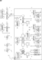
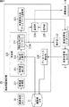
図1は、本発明に係る遊技店の監視システムの一実施の形態の構成を示す図である。 FIG. 1 is a diagram showing a configuration of an embodiment of a game shop monitoring system according to the present invention.
遊技店1−1乃至1−nは、いわゆるパチンコ店、パチスロ店、または、カジノ店である。また、これらの遊技店1−1乃至1−nは、系列店舗または顔画像管理センタや第3者遊技店管理センタの加盟店であって、複数の店舗を統括的に管理する必要のある店舗である。各遊技店1−1乃至1−nは、顔画像管理バス6および第3者遊技店管理バス7により接続されており、それらのバスおよびインターネット等に代表される公衆通信回線網8,9を介して、相互にそれぞれ顔画像情報、および第3者遊技店管理情報を授受している。尚、以降において、遊技店1−1乃至1−nのそれぞれについて、特に区別する必要がない場合、単に、遊技店1と称するものとし、その他の構成についても同様に称するものとする。
The game stores 1-1 to 1-n are so-called pachinko stores, pachislot stores, or casino stores. These amusement stores 1-1 to 1-n are affiliated stores or affiliated stores of the face image management center or the third party amusement store management center, and stores that need to manage a plurality of stores in an integrated manner. It is. Each of the game stores 1-1 to 1-n is connected by a face
顔画像管理バス6は、主に各遊技店1の顔画像認識装置20により管理される顔画像情報を流通させるための伝送路として機能する。また、第3者遊技店管理バス7は、主に各遊技店1の媒体貸出管理装置27により管理される媒体貸出管理情報を流通させるための伝送路として機能する。
The face
顔画像管理センタ2は、顔画像管理センタを管理運営する事業者により使用されるサーバであり、顔画像管理データベース(以降、DBとも称するものとする)3で管理されている登録遊技者DBを各遊技店1により生成される未登録遊技者DBに基づいて更新すると供に、更新した最新の登録遊技者DBを各遊技店1の顔画像認識装置20に対して配信する。
The face
第3者遊技店管理センタ4は、第3者遊技店管理センタを管理運営する事業者により使用されるサーバであり、第3者遊技店管理データベース(DB)5で管理されている媒体貸出管理情報からなるDBを各遊技店1より供給されてくる情報に基づいて更新すると供に、更新した最新の媒体貸出管理情報を各遊技店1の媒体貸出管理装置27に対して配信する。
The third-party amusement
顔画像認識装置20は、カメラ38−1乃至38−mにより撮像された画像より画像処理ユニット39−1乃至39−mにより抽出されて、顔画像情報バス31を介して供給されてくる顔画像の情報に基づいて、顔画像情報データベース21に予め登録されている顔画像と照合し、一致する場合、登録遊技者の来店を携帯端末19に通知したり、LCD(Liquid Crystal Display)または有機EL(Electronic Luminescence)などからなる表示部22に表示する。また、顔画像情報データベース21に予め登録されている顔画像と照合し、一致しない場合、顔画像認識装置20は、顔画像管理データベース3にアクセスし、未登録者として未登録遊技者DBに登録する。
The face
遊技店管理装置24は、いわゆるホールコンピュータと呼ばれるものであり、遊技店管理情報バス30を介して遊技台36−1乃至36−mの動作を監視している。遊技店管理装置24は、遊技台36の出玉もしくはメダルの払い出しの情報、各遊技台36−1乃至36−mの遊技者の呼び出し情報、またはエラーの発生などの監視状況に応じて、所定の処理を実行し、実行結果をLCDや有機ELなどからなる表示部25に表示する。遊技店管理装置24は、計数機35、遊技台36−1乃至36−m、および遊技台周辺端末37−1乃至37−mのそれぞれより供給されてくる情報を、それぞれを識別する識別情報(例えば、遊技台番号)とを対応付けて遊技台管理データベース26により管理する。また、遊技店管理装置24は、遊技台36のそれぞれに設けられているカメラ38を識別するカメラID毎に、遊技台36本体のどのあたりに設置されたかを示す設置位置情報(カメラ38の設置位置、および撮像方向)と、カメラ38により画像が撮像されたとき、その画像内において、遊技者の顔画像を最も認識し易い画像内の適正位置(画像内位置、画サイズ、および顔向きの情報を含む)とを対応付けて適正パラメータとして記憶しており、適正パラメータからなるカメラ位置情報データベース23として管理している。また、カメラ位置情報データベース23は、顔画像情報バス31を介して画像処理ユニット39よりアクセス可能である。これにより、画像処理ユニット39は、それぞれのカメラ38の設置位置の情報に対応する画像内の適正パラメータを読み出し、その画像内の適正位置と略一致する位置の顔画像のみを顔画像認識装置20に供給する。
The game
媒体貸出管理装置27は、精算販売機33、および貸出機34からの情報に基づいて、貸し出される遊技媒体の媒体貸出管理情報を媒体貸出管理データベース29を用いて管理すると供に、媒体貸出管理データベース29に登録されている媒体貸出管理情報を更新する際、その更新情報を、第3者遊技店管理バス7および公衆通信回線網9を介して第3者遊技店管理センタ4に送る。さらに、媒体貸出管理装置27は、第3者遊技店管理バス7および公衆通信回線網9を介して第3者遊技店管理センタ4により供給されてくる媒体貸出管理情報を取得し、媒体貸出管理データベース29に蓄積させる。
The medium
貸出機34は、遊技者が遊技台36で遊技する際、現金やプリペイドカードなどにより所定の金額を受け付けると、金額に応じた個数の遊技媒体を貸し出す。この際、貸出機34は、受け付けた現金やプリペイドカードの残数などの情報と供に、貸し出した遊技媒体の個数の情報を媒体貸出管理装置27に供給する。これにより、媒体貸出管理装置27は、受け付けた現金やプリペイドカードの残数などの情報と供に、貸し出した遊技媒体の個数の情報を媒体貸出管理データベース29に登録する。
The lending machine 34 lends a number of game media according to the amount when the player accepts a predetermined amount by cash or a prepaid card when playing on the gaming table 36. At this time, the lending machine 34 supplies information on the number of lent gaming media to the medium
精算販売機33は、貸球を借りるための度数をつけてプリペイドカードを販売する。このとき、精算販売機33は、販売したプリペイドカードの度数と払いうけた金額とを媒体貸出管理装置27に供給する。また、精算販売機33は、プリペイドカードなどの度数として貸し出した遊技媒体の残数に基づいて現金を精算して払い出す。このとき、精算販売機33は、プリペイドカードの残数と払い戻した現金の金額を媒体貸出管理装置27に供給する。
The
計数機35は、遊技者が遊技台36により遊技することにより獲得した遊技媒体の数を、計数し、計数結果を磁気カードやレシートなどとして出力する。 The counter 35 counts the number of game media acquired by the player playing on the game table 36, and outputs the counting result as a magnetic card or a receipt.
遊技台36−1乃至36−mは、遊技者により所定の操作がなされることにより、遊技を実行し、いわゆる小当たりや大当たりに応じて、遊技球、または、メダルを払い出す。 The game machines 36-1 to 36-m execute a game when a predetermined operation is performed by the player, and pay out a game ball or a medal according to a so-called small hit or big hit.
遊技台周辺端末37−1乃至37−mは、各遊技台36−1乃至36−mに対応して設けられている、いわゆる台間機であり、台間球貸機(原理的には、貸出機34と同様のもの)などが設けられている。また、遊技台周辺端末37は、遊技台36を遊技する遊技者の顔画像情報を取得し、遊技台識別情報(遊技台番号)と共に顔画像認識装置20に送信する。尚、図1においては、顔画像情報を取得する機能として、遊技者の顔画像を取得するカメラ38−1乃至38−mが設けられている例が示されている。
The game console peripheral terminals 37-1 to 37-m are so-called pedestrian machines provided corresponding to the respective game machines 36-1 to 36-m. The same as the lending machine 34) is provided. Further, the gaming machine peripheral terminal 37 acquires the face image information of the player who plays the
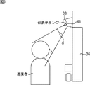
カメラ38−1乃至38−mは、例えば、図2で示されるように、各遊技台36−1乃至36−4のそれぞれの上部に設けられた台表示ランプ61−1乃至61−4の下部に図3で示されるように、読取範囲δ内に遊技者が撮像できるように設け、顔画像を撮像するようにしてもよく、このようにすることにより、各カメラIDは、同時に遊技台IDとして使用することが可能となる。 For example, as shown in FIG. 2, the cameras 38-1 to 38-m are arranged below the table display lamps 61-1 to 61-4 provided on the respective upper sides of the game tables 36-1 to 36-4. As shown in FIG. 3, a face image may be taken so that the player can take an image within the reading range δ. Can be used.
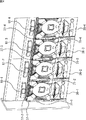
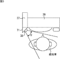
また、カメラ38−1乃至38−mは、例えば、図4で示されるように、遊技台周辺端末37−1乃至37−4に凸部71−1乃至71−4を設け、図5で示されるように読取範囲θ内に遊技者の顔画像が撮像できるように設けるようにしてもよい。 Further, as shown in FIG. 4, the cameras 38-1 to 38-m are provided with convex portions 71-1 to 71-4 on the gaming machine peripheral terminals 37-1 to 37-4, as shown in FIG. As described above, it may be provided so that a player's face image can be captured within the reading range θ.
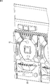
さらに、カメラ38−1乃至38−mは、例えば、図6で示されるように、遊技台36の中央部(遊技台36の盤面上)に設けるようにして、撮像するようにしてもよい。すなわち、図6の設置部81にカメラ38が設置されることにより、図7で示されるように、読取範囲φ内に遊技者を撮像する。
Further, for example, as shown in FIG. 6, the cameras 38-1 to 38-m may be provided at the center of the game table 36 (on the board surface of the game table 36) to take an image. That is, by installing the
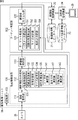
次に、図8を参照して、画像処理ユニット39の構成例について説明する。
Next, a configuration example of the
画像処理ユニット39は、顔画像検出部101、ターゲット特定部102、および記録部103より構成されている。顔画像検出部101は、カメラ38より供給されてくる画像より顔画像を検出して、ターゲット特定部102に供給する。ターゲット特定部102は、供給されてきた顔画像のうち顔画像の認識処理に適正な顔画像をターゲットとして特定し、ターゲットとして特定した顔画像を顔画像認識装置20に供給する。記録部103は、カメラ38より供給されてくる画像を順次、監視画像として記録する。尚、カメラ38は、比較的広角度の画像を撮像しているため、遊技台正面に着座している遊技者のみならず、その背後の画像も記録することができる。したがって、各画像処理ユニット39の記録部103で記録されている画像を用いることにより、遊技台36の周辺の不正行為などを監視することもできる。
The
顔画像検出部101は、画像取得部111、顔画像検出処理部112、および顔画像取得部113を備えている。画像取得部111は、カメラ38により撮像された画像を取得し、顔画像検出処理部112に供給する。顔画像検出処理部112は、画像取得部111より供給されてきた画像内に、顔を構成する部位の配置などのパターンにより顔画像からなる矩形画像を抽出して顔画像取得部113に供給する。
The face
顔画像検出処理部112は、顔画像抽出部131、信頼度計算部132、位置計算部133、サイズ計算部134、および顔向き測定部135を備え、顔画像を抽出すると共に、信頼度、画像内における顔画像の位置、顔画像のサイズ、および顔画像における顔向きの情報を検出する。
The face image
顔画像抽出部131は、撮像された画像の色などから肌が露出した部分であって、目や鼻といった特徴的な部位(器官)の配置などから顔画像を抽出(検出)する。信頼度計算部132は、顔画像として検出された顔画像における、顔画像としての信頼度を計算する。具体的には、信頼度計算部132は、例えば、目、鼻、口、または、耳などの顔画像を構成する各器官の位置を認識し、各器官の配置や距離などに基づいて、標準的な配置、および距離との比率を求めて、これらを正規化するなどした値を信頼度として計算する。
The face
位置計算部133は、例えば、図9で示されるように、矩形状の顔画像FPの左上、右上、左下、および右下の座標を、例えば、ピクセル単位で求め、これらの座標を顔画像の位置として計算する。 For example, as illustrated in FIG. 9, the position calculation unit 133 obtains the coordinates of the upper left, upper right, lower left, and lower right of the rectangular face image FP, for example, in units of pixels, and calculates these coordinates of the face image. Calculate as position.
サイズ計算部134は、位置計算部133により求められた顔画像の座標の情報に基づいて、縦および横方向のサイズを、例えば、ピクセル単位で計算する。位置計算部133は、顔画像として検出された矩形状の顔画像FPの4箇所の角の座標位置を計算する。 The size calculator 134 calculates the vertical and horizontal sizes, for example, in units of pixels based on the coordinate information of the face image obtained by the position calculator 133. The position calculation unit 133 calculates the coordinate positions of the four corners of the rectangular face image FP detected as the face image.
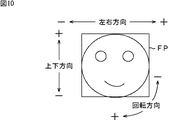
顔向き測定部135は、器官として抽出された目、鼻、口、または耳などの配置から顔の向きを特定する情報を測定する。より具体的には、顔向き測定部135は、上下方向測定部141、左右方向測定部142、および回転方向測定部143を備えており、上下方向測定部141を制御することにより、図10で示されるように、顔画像の上下方向の角度を測定させ、左右方向測定部142を制御して、図10で示されるように、左右方向の角度を測定させ、さらに、回転方向測定部143を制御して、図10で示されるように、顔画像の中心を軸として回転角度を測定させる。
The face orientation measurement unit 135 measures information for specifying the face orientation from the arrangement of the eyes, nose, mouth, ears, or the like extracted as an organ. More specifically, the face direction measurement unit 135 includes an up / down
顔画像取得部113は、顔画像検出処理部112より供給されてくる顔画像をのうち、信頼度の高いものをターゲット特定部102に送信する。この際、顔画像には、撮像された画像の撮像時刻、撮像したカメラ38を識別するカメラIDと共に、顔画像のサイズ(a(pixel)×b(pixel))、上下方向の角度、左右方向の角度、および回転角度を含む顔向き情報(s,t,u)(=sは上下方向の角度であり、tは左右方向の角度であり、uは回転角度である)、並びに、顔画像の画像内位置(e,f,g,h)(=(左上の座標,右上の座標,左下の座標,右下の座標))が付加された状態でターゲット特定部102に供給される。
The face
ターゲット特定部102は、ターゲット判定部121、および顔画像切り出し部122より構成されている。
The
ターゲット判定部121は、顔画像検出部101より供給されてきた顔画像に含まれているカメラIDに基づいて、カメラ位置情報データベース23より適正パラメータを読み出して、顔画像のサイズ、上下方向の角度、左右方向の角度、および回転角度を含む顔向き情報、並びに、顔画像の位置情報に基づいて、顔画像認証処理に適した適正な顔画像であるか否かを判定し、判定結果と共に顔画像を顔画像切り出し部122に供給する。
The
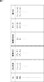
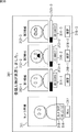
カメラ位置情報データベース23は、例えば、図11で示されるように、カメラIDに対応付けて、設置位置、撮像方向、画像内位置、サイズ、および顔向きの情報からなる適正パラメータが記憶されたテーブルから構成されている。図11においては、カメラID=001のカメラ38は、遊技台36の正面からみて(水平方向,垂直方向)=(x1,y1)の設定位置に、撮像方向が(左右方向の角度,垂直方向の角度)=(θ1,φ1)に向けられて設置されていることが示され、図12で示されるように、撮像される画像P内における領域Z5が適正位置であり、そのサイズが(Apixel×Bpixel)であり、さらに、顔向き情報が(s1,t1,u1)であることが示されている。
For example, as shown in FIG. 11, the camera
また、カメラID=002のカメラ38は、遊技台36の正面からみて(水平方向,垂直方向)=(x2,y2)の設定位置に、撮像方向が(左右方向の角度,垂直方向の角度)=(θ2,φ2)に向けられて設置されていることが示され、図13で示されるように、撮像される画像P内における領域Z11が適正位置であり、そのサイズが(Cpixel×Dpixel)であり、さらに、顔向きが(s2,t2,u2)であることが示されている。
In addition, the
尚、図12,図13においては、左部が遊技台36と、遊技台36におけるカメラ38の設置位置を示しており、右部がカメラ38により撮像された画像Pを水平方向に3領域、垂直方向に4領域に分割し、領域Z1乃至Z12からなる合計12領域に分割した例を示している。尚、画像Pにおける領域分割は、12領域以外の領域数に分割するようにしても良いものである。
In FIG. 12 and FIG. 13, the left part shows the game stand 36 and the installation position of the
さらに、ターゲット判定部121は、パラメータ読出部151、画像内位置判定部152、サイズ判定部153、および顔向き判定部154を備えている。パラメータ読出部151は、カメラIDに基づいて、予めカメラ位置情報データベース23にカメラIDで識別される設置位置、および撮像角度の情報に対応付けて記憶されている、画像内位置、サイズ、および顔向き情報からなる適正パラメータを読み出す。
Further, the
画像内位置判定部152は、適正パラメータのうち、画像内位置の情報と、供給されてきた顔画像に付されている顔画像位置とを比較し、一致するか否かを判定する。すなわち、例えば、顔画像がカメラID=001により撮像された画像によるものである場合、図11で示されるように、適正パラメータとして領域Z5が読み出されるので、顔画像の画像内位置(e,f,g,h)が領域Z5内であるか、または、略領域Z5内に含まれるか否かが判定される。
The in-image
また、サイズ判定部153は、適正パラメータのうち、顔画像のサイズの情報と、供給されてきた顔画像のサイズとを比較し、一致するか否かを判定する。すなわち、例えば、カメラID=001により撮像された画像によるものである場合、図11で示されるように、適正パラメータとしてA×Bが読み出されるので、顔画像のサイズ(a×b)が略同一であるか否かにより一致するか否かが判定される。
Also, the
さらに、顔向き判定部154は、適正パラメータのうち、顔向き情報と、供給されてきた顔画像に付されている顔向き情報とを比較し、一致するか否かを判定する。すなわち、例えば、カメラID=001により撮像された画像によるものである場合、図11で示されるように、適正パラメータとして顔向き情報(s1,t1,u1)が読み出されるので、顔画像の顔向き情報(s,t,u)が略同一であるか否かにより一致するか否かが判定される。
Further, the face
ターゲット判定部121は、これらの判定結果と共に顔画像を顔画像切り出し部122に供給する。
The
顔画像切り出し部122は、ターゲット判定部121の判定結果がいずれも一致している場合、その顔画像を顔画像認証に適したものであるとして顔画像認識装置20に供給する。
If all the determination results of the
次に、図14を参照して、顔画像認識装置20の構成例について説明する。
Next, a configuration example of the face
顔画像取得部221は、画像処理ユニット39より供給される顔画像を取得し、照合部222に供給する。照合部222は、顔画像取得部221により取得された顔画像と、顔画像情報DB21に予め登録されている登録遊技者の顔画像とを照合し、類似度の高い候補となる顔画像があれば、第3候補までの顔画像を照合結果として表示部22に表示させる。また、照合部222は、類似度の高い候補となる顔画像が存在しない場合、供給されてきた顔画像を未登録遊技者データベース登録部223に供給する。
The face
より詳細には、照合部222の特徴量抽出部231は、顔画像を識別するための特徴量を抽出して、顔画像と共に類似度計算部232に供給する。類似度計算部232は、顔画像情報DB21に登録されている登録遊技者の顔画像の特徴量を抽出すると供に、特徴量抽出部231より供給されてくる特徴量とを用いて、顔画像情報DB21に登録されている全ての登録遊技者の顔画像との類似度を求め、顔画像取得部221より供給されてきた顔画像、および、類似度が上位3位までの顔画像を類似度判定部233に供給する。より具体的には、類似度計算部232は、例えば、目と目の間隔、あごから額までの長さと、あごから鼻までの長さの比率などの各種の顔の特徴量に基づいて、それぞれの差分和、平均比率、または比率和などを類似度として求める。
More specifically, the feature
類似度判定部233は、類似度計算部232より供給されてくる類似度を順次バッファ233aに蓄積し、上位3位となる顔画像のそれぞれの類似度のうち、1位となる顔画像との類似度と、所定の閾値とを比較し、比較結果に基づいて、1位となる登録顔画像が、顔画像取得部221より供給されてきた顔画像に対して類似している場合(類似度が高い程類似していることを示す類似度の場合、所定の閾値よりも高いとき、また、類似度が低い程類似していることを示す類似度の場合、所定の閾値よりも低いとき)、上位3位となる顔画像と類似度の情報を表示部22に供給して、表示させると供に、通信部224に供給する。また、類似度判定部233は、1位となる顔画像との類似度と、所定の閾値とを比較し、比較結果に基づいて、1位となる登録顔画像が、顔画像取得部221より供給されてきた顔画像に対して類似していない場合、顔画像取得部221より供給されてきた顔画像を未登録遊技者データベース登録部223に供給する。
The
未登録遊技者データベース登録部223は、照合部222より未登録であるとみなされて供給されてきた、顔画像を顔画像管理データベース3に登録する。
The unregistered player
操作部225は、ボタン、マウス、または、キーボードなどから構成され、上述した類似度が上位3位となる、表示部22に表示された顔画像のいずれかが選択されるとき操作され、操作結果を通信部224に供給する。通信部224は、モデムなどから構成され、操作部225からの操作信号に基づいて、選択された顔画像を携帯端末19に配信する。
The operation unit 225 includes buttons, a mouse, a keyboard, and the like. The operation unit 225 is operated when any one of the face images displayed on the
尚、ここでは、類似度は、例えば、比率和で示されるような登録遊技者として登録されている顔画像に近いほど高い値を示すものであるとし、類似度が所定の閾値よりも高い値であるとき、その類似度に対応する登録遊技者の顔画像であるものとして判定する例について説明する。しかしながら、例えば、類似度が撮像された顔画像と登録遊技者として登録されている顔画像とのそれぞれの特徴量における差分和として表現されている場合、類似度判定部233は、類似度が閾値よりも小さければ、撮像された顔画像が登録遊技者の顔画像であるとみなすことになり、または、平均比率などの場合、0乃至1の範囲で所定の値以上であって、1に近い値であれば、同一の人物であるとみなすことができる。
Here, for example, the similarity indicates a higher value as it is closer to the face image registered as a registered player as indicated by the ratio sum, and the similarity is a value higher than a predetermined threshold value. In this case, an example will be described in which it is determined that the face image of the registered player corresponding to the similarity is. However, for example, when the similarity is expressed as a difference sum in each feature amount between the captured face image and the face image registered as the registered player, the
データベース管理部226は、顔画像管理センタ2より新たな登録遊技者データベースが配信されてくると、新たな登録遊技者データベース252に基づいて、顔画像情報DB21を更新する。
When a new registered player database is distributed from the face
次に、図15のフローチャートを参照して、登録遊技者来店監視処理について説明する。 Next, the registered player visit monitoring process will be described with reference to the flowchart of FIG.
ステップS1において、カメラ38は、設置されている範囲の画像を撮像し、撮像した画像を画像処理ユニット39に供給する。画像処理ユニット39の画像取得部111は、供給された画像を取得し、顔画像検出処理部112に供給する。
In step S <b> 1, the
ステップS2において、顔画像検出処理部112の顔画像抽出部131は、供給された画像より遊技者の顔画像を抽出(検出)する。より具体的には、顔画像抽出部131は、例えば、撮像された画像の色などから肌が露出した部分であって、目や鼻といった特徴的な部位の配置などから顔画像を抽出(検出)する。このとき、信頼度計算部132は、検出された顔画像の信頼度trを計算する。
In step S2, the face
ステップS3において、顔画像検出処理部112は、信頼度計算部132により計算された信頼度trが所定の閾値よりも高いか否かに基づいて、顔画像として抽出された画像が、顔画像であるか否か、すなわち、顔画像が抽出されたか否かを判定する。
In step S3, the face image
ステップS3において、顔画像として抽出された画像が、顔画像ではない、または、顔画像として認識される画像が存在しない、すなわち、顔画像の信頼度trが所定の閾値よりも低く、顔画像が抽出されていないと判定された場合、処理は、ステップS1に戻る。一方、ステップS3において、顔画像が抽出されたと判定された場合、処理は、ステップS4に進む。 In step S3, the image extracted as the face image is not a face image, or there is no image recognized as a face image, that is, the reliability tr of the face image is lower than a predetermined threshold, and the face image is If it is determined that it has not been extracted, the process returns to step S1. On the other hand, if it is determined in step S3 that a face image has been extracted, the process proceeds to step S4.
ステップS4において、顔画像検出処理部112の位置計算部133は、顔画像の画像内位置(e,f,g,h)を計算し、サイズ計算部134は、顔画像の画像内位置(e,f,g,h)より顔画像のサイズ(a×b)を計算し、顔向き測定部135は、上下方向測定部141、左右方向測定部142、および回転方向測定部143を制御して、検出された顔画像の顔向き情報(s,t,u)を計算する。そして、顔画像検出処理部112は、顔画像と共に、その顔画像を含む画像を撮像したカメラ38を識別するカメラID、撮像時刻、信頼度tr、画像内位置(e,f,g,h)、サイズ(a×b)、並びに、顔向き情報(s,t,u)を顔画像取得部113に供給する。顔画像取得部113は、顔画像と共に、その顔画像を含む画像を撮像したカメラ38を識別するカメラID、撮像時刻、信頼度tr、画像内位置(e,f,g,h)、サイズ(a×b)、並びに、顔向き情報(s,t,u)をターゲット特定部102に供給する。
In step S4, the position calculation unit 133 of the face image
ステップS5において、ターゲット特定部102のターゲット判定部121は、供給されてきた顔画像に付されているカメラIDを読み出す。
In step S5, the
ステップS6において、ターゲット判定部121は、パラメータ読出部151を制御して、カメラ位置情報データベース23よりカメラIDに対応する設置位置、撮像方向、画像内位置、サイズ、および顔向きの適正パラメータを読み出す。例えば、カメラIDが001の場合、図11で示されるようなカメラ位置情報データベース23が登録されているようなとき、適正パラメータであるカメラ位置情報として、設置位置(水平方向,垂直方向)=(x1,y1)、撮像方向(左右方向の角度,垂直方向の角度)=(θ1,φ1)、図12で示される画像P内における適正位置(=領域Z5)、顔画像の認証に適正な画像サイズ(Apixel×Bpixel)、および、適正な顔向き情報(s1,t1,u1)が、それぞれ最適パラメータとして読み出される。
In step S <b> 6, the
ステップS7において、ターゲット判定部121は、画像内位置判定部152、サイズ判定部153、および顔向き判定部154を制御して、適正判定処理を実行させ、供給されてきた顔画像に付されている画像内位置(e,f,g,h)、サイズ(a×b)、並びに、顔向き情報(s,t,u)と、適正パラメータとして読み出されたカメラ位置情報である、設置位置(水平方向,垂直方向)=(x1,y1)、撮像方向(左右方向の角度,垂直方向の角度)=(θ1,φ1)、図12で示される画像P内における領適正位置(=領域Z5)、顔画像の認証に適正な画像サイズ(Apixel×Bpixel)、および、適正な顔向き情報(s1,t1,u1)との比較により、供給されてきた顔画像が顔画像認証処理に対して適正であるか否かを判定する。
In step S <b> 7, the
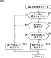
ここで、図16のフローチャートを参照して、適正判定処理について説明する。 Here, the appropriateness determination process will be described with reference to the flowchart of FIG.
ステップS51において、サイズ判定部153は、供給された顔画像のサイズが適正サイズであるか否かを判定する。より具体的には、例えば、カメラIDが001のカメラ38により撮像された画像より抽出された顔画像の場合、供給されてきた顔画像のサイズであるサイズ(a×b)が、適正サイズである(A×B)の近傍のサイズであるか否かが判定される。より詳細には、サイズ判定部153は、例えば、供給されてきた顔画像のサイズであるサイズ(a×b)のうち、水平方向のサイズaが、水平方向の適正なサイズであるサイズAの許容範囲内(A−At)<a<(A+At)(Atは許容範囲)であり、かつ、垂直方向のサイズbが、垂直方向の適正なサイズであるサイズBの許容範囲内(B−Bt)<b<(B+Bt)(Btは許容範囲)であり、適正サイズである(A×B)の近傍のサイズであって、供給されてきた顔画像のサイズが適正サイズであるか否かを判定する。
In step S51, the
すなわち、カメラ38により撮像された顔画像のサイズが適正サイズであるか否かは、カメラ38の設置位置と、顔画像の人物との距離が適切であるか否かが判定されていることに等しい。つまり、遊技台36に向かって着座している遊技者の顔画像をターゲットとしたい場合、遊技台36の着座位置に遊技者が着座したときに、カメラ38で撮像可能な視野内、すなわち、画像内における遊技者の顔画像のサイズとしてとり得るサイズが、カメラ位置情報データベース23に記憶されているので、この処理により、カメラ38の設置位置から、抽出された顔画像の人物までの距離が、適正な距離であるか否かが判定される。
That is, whether or not the size of the face image captured by the
そこで、ステップS51において、例えば、供給されてきた顔画像のサイズであるサイズ(a×b)のうち、水平方向のサイズaが、水平方向のサイズAの許容範囲内(A−At)<a<(A+At)であり、かつ、垂直方向のサイズbが、垂直方向のサイズBの許容範囲内(B−Bt)<b<(B+Bt)であり、適正サイズである(A×B)の近傍のサイズであって、供給されてきた顔画像のサイズが適正サイズであると判定された場合、処理は、ステップS52に進む。 Therefore, in step S51, for example, of the supplied face image size (a × b), the horizontal size a is within an allowable range of horizontal size A (A−At) <a. <(A + At), and the vertical size b is within the allowable range of the vertical size B (B−Bt) <b <(B + Bt), and is close to the appropriate size (A × B) If it is determined that the size of the supplied face image is an appropriate size, the process proceeds to step S52.
ステップS52において、顔向き判定部154は、例えば、供給されてきた顔画像の顔向きが適正であるか否かを判定する。より具体的には、例えば、カメラIDが001のカメラ38により撮像された画像より抽出された顔画像の場合、供給されてきた顔画像の顔向きである顔向き情報(s,t,u)が、適正な顔向き情報(s1,t1,u1)の近傍の角度となっているか否かが判定される。より詳細には、顔向き判定部154は、供給されてきた顔画像の顔向きである顔向き情報(s,t,u)のうち、水平方向の顔向きである角度sが、水平方向の適正な角度s1の許容範囲内(s1−s1t)<s<(s1+s1t)(s1tは許容範囲)であり、かつ、垂直方向の顔向きの角度tが、垂直方向の適正な角度t1の許容範囲内(t1−t1t)<t<(t1+t1t)(t1tは許容範囲)であり、かつ、回転方向の顔向きの角度uが、回転方向の適正な角度u1の許容範囲内(u1−u1t)<u<(u1+u1t)(u1tは許容範囲)であって、供給されてきた顔画像の顔向きが適正であるか否かを判定する。
In step S52, the face
すなわち、顔画像認証処理では、一般に、目、口、鼻、または、耳などの器官の配置などを利用して、登録された顔画像との比較がなされるが、登録されている顔画像は、一般に正面方向から撮像した顔画像であるので、顔向きが正面に近いものから離れるにつれて、正しく認識することができなくなり、認識精度が低下する。そこで、顔画像認証処理に必要とされる顔画像のうち、登録されている顔画像、すなわち、正面方向から撮像した顔向きであって、顔画像認証に適正な顔画像であるか否かが判定される。 That is, in the face image authentication process, generally, the arrangement of an organ such as eyes, mouth, nose, or ear is used for comparison with the registered face image. In general, since the face image is taken from the front direction, the face cannot be correctly recognized as the face is moved away from the one close to the front, and the recognition accuracy is lowered. Therefore, among the face images required for the face image authentication process, it is determined whether or not the registered face image is a face image captured from the front direction and appropriate for face image authentication. Determined.
ステップS52において、顔向き判定部154は、例えば、供給されてきた顔画像の顔向きである顔向き情報(s,t,u)のうち、水平方向の顔向きである角度sが、水平方向の適正な角度sの許容範囲内(s1−s1t)<s<(s1+s1t)(s1tは許容範囲)であり、かつ、垂直方向の顔向きの角度tが、垂直方向の適正な角度tの許容範囲内(t1−t1t)<t<(t1+t1t)(t1tは許容範囲)であり、かつ、回転方向の顔向きの角度uが、回転方向の適正な角度u1の許容範囲内(u1−u1t)<u<(u1+u1t)(u1tは許容範囲)であって、供給されてきた顔画像の顔向きが適正であると判定された場合、処理は、ステップS53に進む。
In step S52, the face
ステップS53において、画像内位置判定部152は、供給されてきた顔画像の画像内位置が適正であるか否かを判定する。より具体的には、例えば、カメラIDが001のカメラ38により撮像された画像より抽出された顔画像の場合、供給されてきた顔画像の画像内位置である画像内位置(e,f,g,h)より、適正な領域である領域Z5の近傍であるか否かが判定される。より詳細には、顔向き判定部154は、供給されてきた顔画像の画像内位置である画像内位置(e,f,g,h)により、画像内位置の重心位置を求め、適正な領域であるZ5の重心位置との距離が所定範囲内であるか否かにより、供給されてきた顔画像の画像内位置が適正であるか否かを判定する。
In step S53, the in-image
すなわち、カメラ38は、固定されており、さらに、監視画像として記録する必要があるため、比較的広角度の広い視野の画像として撮像されている。このため、カメラ38の設置位置と撮像角度により、撮像される画像内における、遊技台36の着座位置に着座している人物の顔画像は様々な画像内位置をとることになる。
That is, since the
例えば、図12の左部で示されるように、遊技台36の正面中央部にカメラ38が設置されるような場合、図12の右部で示されるように、カメラ38で撮像される画像の中央に近い領域Z5に、遊技台36に着座した遊技者の顔画像は配置されて撮像される。しかしながら、図13の左部で示されるように、遊技台36の左上部にカメラ38が設置されるような場合、図13の右部で示されるように、カメラ38で撮像される画像の中央に近い領域Z7に、遊技台36に着座した遊技者の顔画像は配置される。尚、図12,図13においては、カメラ38の撮像方向はいずれも同一の正面方向であるものとする。
For example, as shown in the left part of FIG. 12, when the
そこで、遊技台36に着座している遊技者の顔画像が撮像され得る領域、すなわち、図12であれば、領域Z5を、図13であれば、領域Z7を、それぞれ適正な領域として設定し、その領域に存在する顔画像を遊技台36で遊技する遊技者の顔画像であるものとして特定する。 Therefore, an area where the face image of the player sitting on the game table 36 can be captured, that is, the area Z5 in FIG. 12 and the area Z7 in FIG. 13 are set as appropriate areas. Then, the face image existing in the area is specified as the face image of the player who plays on the game table 36.
ステップS53において、例えば、カメラIDが001の場合、供給されてきた顔画像の画像内位置である画像内位置(e,f,g,h)の重心位置が、適正な領域であるZ5の重心位置との距離が所定範囲内であって、供給されてきた顔画像の画像内位置が適正であると判定されたとき、ステップS54において、ターゲット判定部121は、供給されてきた顔画像が、顔画像認識処理に適した顔画像である、すなわち、ターゲットの顔画像であるものとみなし、顔画像認証に適正な顔画像であることを示す判定結果と共に、その顔画像を顔画像切り出し部122に供給する。
In step S53, for example, when the camera ID is 001, the center of gravity of the position (e, f, g, h) in the image, which is the position in the image of the supplied face image, is the center of gravity of Z5, which is an appropriate region. When it is determined that the distance to the position is within a predetermined range and the position of the supplied face image in the image is appropriate, in step S54, the
一方、ステップS51において、適正サイズではないと判定された場合、ステップS52において、顔向きが適正範囲ではないと判定された場合、または、ステップS53において、画像内位置が適正範囲ではないと判定された場合、ステップS55において、供給されてきた顔画像が、顔画像認識処理に適した顔画像ではないと判定され、判定結果のみが顔画像切り出し部122に供給される。
On the other hand, if it is determined in step S51 that the size is not appropriate, if it is determined in step S52 that the face orientation is not in the proper range, or in step S53, it is determined that the position in the image is not in the proper range. In step S55, it is determined that the supplied face image is not a face image suitable for the face image recognition process, and only the determination result is supplied to the face
すなわち、ターゲット判定部121は、供給されてきた顔画像のうち、顔画像のサイズが適正であり、かつ、顔向きが適正であり、かつ、画像内位置が適正である場合に、その顔画像が、顔画像認証処理に適正な顔画像であるものと判定する。
In other words, the
ここで、図15のフローチャートの説明に戻る。 Now, the description returns to the flowchart of FIG.
ステップS8において、顔画像切り出し部122は、適正判定処理の判定結果が適正であったか否かを判定する。例えば、上述したステップS55の処理により、適正な顔画像ではないと判定された場合、処理は、ステップS1に戻る。
In step S8, the face
一方、ステップS8において、例えば、ステップS54の処理により、適正な顔画像であると判定された場合、ステップS9において、顔画像切り出し部122は、供給されてきた顔画像を顔画像認識装置20に送信する。この際、顔画像切り出し部122は、カメラ38のそれぞれを識別するカメラIDや、撮像時刻の情報などの情報を顔画像に付加して顔画像認識装置20に送信する。
On the other hand, if it is determined in step S8 that the face image is an appropriate face image by the process in step S54, for example, the face
以上の処理により、カメラ38により撮像された画像より抽出された顔画像のうち、顔画像認識処理に適正であると判定された顔画像のみが、顔画像認識装置20に供給されることになるので、顔画像認識に適さないと判定される顔画像については、顔画像認識装置20に供給されないため、顔画像認証処理における認証精度を向上させることが可能になるとと共に認証精度が低い可能性の高い顔画像が、顔画像認識装置20には供給されないことになるので、認識精度の低い顔画像を用いた顔画像認証処理が低減されるので、顔画像認識装置20の処理負荷を低減させることが可能となる。また、遊技台36の遊技者の顔画像を撮像するためのカメラを別途設ける必要がなく、遊技台36に着座した遊技者の顔画像を撮像するためのカメラと、遊技台36周辺の不正行為を監視するための画像を撮像するカメラとを共用することが可能となり、カメラの設置コストを低減することが可能となる。
As a result of the above processing, only the face images determined to be appropriate for the face image recognition process among the face images extracted from the image captured by the
ステップS21において、顔画像認識装置20の顔画像取得部221は、顔画像を取得する。ステップS22において、顔画像取得部221は、供給された顔画像のうち、いずれか未処理の1つを抽出し、特徴量抽出部231に供給する。
In step S21, the face
ステップS23において、照合部222の特徴量抽出部231は、供給されてきた顔画像より特徴量を抽出して、顔画像と供に類似度計算部232に供給する。
In step S23, the feature
ステップS24において、類似度計算部232は、類似度計算処理を実行する。
In step S24, the
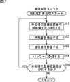
ここで、図17のフローチャートを参照して、類似度計算処理について説明する。 Here, the similarity calculation processing will be described with reference to the flowchart of FIG.
ステップS61において、類似度計算部232は、顔画像情報DB21に登録されている顔画像のうち、未処理の1つの登録遊技者の顔画像を抽出し、処理対象に設定する。
In step S61, the
ステップS62において、類似度計算部232は、処理対象として設定した顔画像情報DB21に登録されている顔画像より、前記特徴量抽出部231より供給されてきた特徴量と同様の特徴量を抽出する。尚、ここで、抽出される特徴量は、顔画像検出部112により抽出される顔画像位置、サイズ、および顔向き情報よりも、より詳細なものであって、認識精度の高いパラメータとなる。
In step S62, the
ステップS63において、類似度計算部232は、特徴量抽出部231より供給された顔画像についての、目と目の間隔、あごから額までの長さと、あごから鼻のまでの長さの比率などの各種の顔の特徴量と、顔画像情報DB21に登録されている顔画像における同様の特徴量とを用いて、それぞれの差分和、平均比率、または比率和などを類似度として計算し、ステップS64において、計算結果である顔画像情報DB21に登録されている顔画像との類似度を類似度判定部233に供給し、バッファ233aに登録させる。
In step S <b> 63, the
ステップS65において、類似度計算部232は、顔画像情報DB21の登録遊技者DB252に未処理の登録遊技者の顔画像が存在するか否かを判定し、未処理の登録遊技者の顔画像が存在する場合、処理は、ステップS61に戻る。すなわち、顔画像情報DB21の全ての登録遊技者の顔画像との類似度が計算されるまで、ステップS61乃至S65の処理が繰り返される。そして、ステップS65において、顔画像情報DB21に未処理の登録遊技者の顔画像が存在しないと判定された場合、類似度計算処理は終了する。
In step S65, the
ここで、図16のフローチャートの説明に戻る。 Now, the description returns to the flowchart of FIG.
ステップS25において、類似度判定部233は、バッファ233aに登録されている類似度の計算結果に基づいて順位を求め、顔画像情報DB21に登録されている顔画像のうちの上位3位までの顔画像と類似度の情報を抽出する。そして、類似度判定部233は、上位3位までの顔画像と類似度の情報に基づいて、最上位の類似度が所定の閾値よりも大きいか否かを判定する。すなわち、類似度判定部233は、最も類似している登録遊技者(顔画像情報DB21に登録されている顔画像のうち、顔画像取得部221により取得された顔画像と最も類似している登録遊技者:ここでは、類似度の最も高い登録遊技者)の類似度を所定の閾値と比較する。
In step S25, the
尚、上述のように、類似度の定義により、撮像された顔画像と最も類似している登録遊技者の顔画像との類似度は、その値そのものが最も高いとは限らないため、類似度と閾値との大小関係はこの例の場合とは異なることがある。 Note that, as described above, the similarity between the face image of the registered player who is most similar to the captured face image is not necessarily the highest because of the definition of the similarity. And the threshold value may differ from those in this example.
ステップS25において、最上位の類似度が所定の閾値よりも大きいと判定された場合、ステップS26において、類似度判定部233は、類似度計算部232より供給されてきた上位3位の顔画像が登録遊技者の顔画像の候補であることを示す報知画面301を表示部22を制御して表示させる。
If it is determined in step S25 that the highest similarity is greater than a predetermined threshold, in step S26, the
このとき、例えば、図18で示されるような報知画面301が、表示部22に表示される。
At this time, for example, a
図18の報知画面301においては、カメラ画像表示欄311が、左中段に設けられており、画像処理ユニット39より供給されてきた顔画像が表示される。また、その右側には、類似度の高い順に第1候補乃至第3候補までの類似度の上位3位の登録遊技者の顔画像表示欄312−1乃至312−3が設けられている。さらに、各登録遊技者の顔画像表示欄312−1乃至312−3の下には、類似度レベル表示欄313−1乃至313−3が設けられており、類似度のレベルが表示されている。図18において、黒で示される領域の横方向の長さが類似度の大きさを示している。
In the
また、類似度レベル表示欄313−1乃至313−3の下には、対応する位置に、ID表示欄314−1乃至314−3が設けられており、各顔画像の顔画像情報DB21における顔画像を識別するIDが表示されており、図18において、左から「00051」、「00018」および「00022」と表示されている。
In addition, ID display fields 314-1 to 314-3 are provided at corresponding positions below the similarity level display fields 313-1 to 313-3, and the face in the face
さらに、ID表示欄314−1乃至314−3の下には、それぞれ対応する位置に、それぞれの候補を選択されるときに操作部225により操作される確定ボタン318−1乃至318−3が設けられている。 Furthermore, below the ID display fields 314-1 to 314-3, confirmation buttons 318-1 to 318-3 operated by the operation unit 225 when each candidate is selected are provided at the corresponding positions. It has been.
また、カメラ画像表示欄311の下には、その顔画像を撮像したカメラを識別するカメラID表示欄315が設けられており、図18においては、カメラ38を識別するためのカメラIDとして「カメラ02」が表示されている。さらに、カメラID表示欄315の下には、時刻表示欄316が設けられており、カメラ38により撮像された時刻が表示されており、図18においては、「18:23:32」と表示されており、カメラ画像表示欄311の顔画像が18時23分32秒に撮像されていることが示されている。
A camera
さらに、時刻表示欄316の下には、別人ボタン317が設けられており、カメラ画像の顔画像が、第1候補乃至第3候補となる登録遊技者の顔画像表示欄312−1乃至312−3のいずれにも似ていないとみなされたとき、操作部225により操作される。
Furthermore, another person button 317 is provided below the
ステップS27において、通信部224は、操作部225が操作されて、候補となる顔画像の何れかが選択されたか否か、すなわち、例えば、図18で示される報知画面301が表示部22に表示されていた場合、確定ボタン318−1乃至318−3のいずれかが操作部225により操作されたか否かを判定する。
In step S27, the communication unit 224 displays on the
ステップS27において、例えば、確定ボタン318−1が操作された場合、第1候補となる顔画像が選択されたとみなされ、ステップS28において、通信部224は、選択された第1候補となる顔画像およびカメラ38により撮像されたカメラ画像を携帯端末19に送信し、該当する登録遊技者が来店したことを通知する。
In step S27, for example, when the confirm button 318-1 is operated, it is considered that the face image to be the first candidate has been selected, and in step S28, the communication unit 224 has the selected face image to be the first candidate. And the camera image imaged with the
ステップS41において、携帯端末19は、登録遊技者の来店が通知されてきたか否かを判定し、通知されてくるまで、その処理を繰り返す。例えば、ステップS41において、ステップS28の処理により、登録遊技者の来店が通知されてきた場合、ステップS42において、携帯端末19は、顔画像認識装置20より送信されてきた登録遊技者の来店の通知を受信すると供に、その通知に併せて送信されてくる登録遊技者の顔画像およびカメラ38により撮像されたカメラ画像を表示する。
In step S41, the
以上の処理により、遊技店1内の係員は、携帯端末19を所持していると、登録遊技者の来店を認識することが可能となる。
By the above processing, the staff in the
また、ステップS29において、顔画像取得部221は、供給された顔画像の全てについて処理を行なったか否かを判定し、未処理の顔画像がある場合、処理は、ステップS22に戻る。すなわち、全ての顔画像について処理が行なわれるまで、ステップS22乃至S30の処理が繰り返される。そして、全ての顔画像について処理が終了したと判定された場合、処理は、ステップS21に戻る。
In step S29, the face
一方、ステップS27において、いずれの候補となる顔画像も選択されず、例えば、図18の報知画面301における別人ボタン317が押下された場合、または、ステップS25において、類似度計算部232より供給されてくる上位3位までの顔画像と類似度の情報に基づいて、最上位の類似度が所定の閾値よりも大きくない場合、すなわち、最も類似している登録遊技者の顔画像であっても類似度が、所定の閾値未満である場合、ステップS30において、類似度判定部233は、画像処理ユニット39より供給されてきた顔画像を未登録遊技者データベース登録部223に供給する。未登録遊技者データベース登録部223は、供給されてきた顔画像を生体管理情報バス6及び公衆通信回線網8を介して顔画像管理データベース3にアクセスし、登録する。
On the other hand, no candidate face image is selected in step S27. For example, when the other person button 317 on the
以上の処理により、顔画像認識装置20により画像処理ユニット39より供給されてきた顔画像が、顔画像情報DB21に登録されていないとみなされると、顔画像管理センタ2により管理されている顔画像管理DB3内に未登録遊技者の顔画像として登録される。
If the face image supplied from the
以上によれば、顔画像による顔画像認証を実行するに当たり、カメラ38の設置位置、および撮像方向に基づいて、顔画像認証処理に適正な顔画像のみを選択的に顔画像認識装置20に供給し、顔画像認証処理を実行させるようにしたので、広角度の監視用のカメラを設けるのみで、監視画像の取得と、顔認証処理とを実現させることができ、顔認証処理に必要なカメラ、および監視用に必要とされるカメラとを、それぞれ設置する必要がないので、設置コストを低減することが可能となる。また、顔認証処理に適正な顔画像のみが顔画像認識装置20に供給されるので、顔画像認証の認証精度を向上させることが可能となる。
According to the above, when executing the face image authentication by the face image, only the face image appropriate for the face image authentication process is selectively supplied to the face
ところで、上述した一連の監視処理は、ハードウェアにより実行させることもできるが、ソフトウェアにより実行させることもできる。一連の処理をソフトウェアにより実行させる場合には、そのソフトウェアを構成するプログラムが、専用のハードウェアに組み込まれているコンピュータ、または、各種のプログラムをインストールすることで、各種の機能を実行することが可能な、例えば汎用のパーソナルコンピュータなどに、記録媒体からインストールされる。 Incidentally, the series of monitoring processes described above can be executed by hardware, but can also be executed by software. When a series of processing is executed by software, a program constituting the software may execute various functions by installing a computer incorporated in dedicated hardware or various programs. For example, it is installed from a recording medium in a general-purpose personal computer or the like.
図19は、汎用のパーソナルコンピュータの構成例を示している。このパーソナルコンピュータは、CPU(Central Processing Unit)1001を内蔵している。CPU1001にはバス1004を介して、入出力インタフェース1005が接続されている。バス1004には、ROM(Read Only Memory)1002およびRAM(Random Access Memory)1003が接続されている。
FIG. 19 shows a configuration example of a general-purpose personal computer. This personal computer incorporates a CPU (Central Processing Unit) 1001. An input /
入出力インタフェース1005には、ユーザが操作コマンドを入力するキーボード、マウスなどの入力デバイスよりなる入力部1006、処理操作画面や処理結果の画像を表示デバイスに出力する出力部1007、プログラムや各種データを格納するハードディスクドライブなどよりなる記憶部1008、LAN(Local Area Network)アダプタなどよりなり、インターネットに代表されるネットワークを介した通信処理を実行する通信部1009が接続されている。また、磁気ディスク(フレキシブルディスクを含む)、光ディスク(CD-ROM(Compact Disc-Read Only Memory)、DVD(Digital Versatile Disc)を含む)、光磁気ディスク(MD(Mini Disc)を含む)、もしくは半導体メモリなどのリムーバブルメディア1011に対してデータを読み書きするドライブ1010が接続されている。
The input /
CPU1001は、ROM1002に記憶されているプログラム、または磁気ディスク、光ディスク、光磁気ディスク、もしくは半導体メモリ等のリムーバブルメディア1011から読み出されて記憶部1008にインストールされ、記憶部1008からRAM1003にロードされたプログラムに従って各種の処理を実行する。RAM1003にはまた、CPU1001が各種の処理を実行する上において必要なデータなども適宜記憶される。
The
尚、本明細書において、記録媒体に記録されるプログラムを記述するステップは、記載された順序に沿って時系列的に行われる処理は、もちろん、必ずしも時系列的に処理されなくとも、並列的あるいは個別に実行される処理を含むものである。 In the present specification, the step of describing the program recorded on the recording medium is not limited to the processing performed in time series in the order described, but of course is not necessarily performed in time series. Or the process performed separately is included.
また、本明細書において、システムとは、複数の装置により構成される装置全体を表すものである。 Further, in this specification, the system represents the entire apparatus constituted by a plurality of apparatuses.
1,1−1乃至1−n 遊技店
2 顔画像管理センタ
3 顔画像管理データベース
4 第3者遊技店管理センタ
5 第3者遊技店管理データベース
6 顔画像管理バス
7 第3者遊技店管理バス
8,9 公衆通信回線網
21 顔画像認識装置
22 顔画像情報データベース
24 遊技店管理装置
26 遊技台管理データベース
27 媒体貸出管理装置
29 媒体貸出管理データベース
30 遊技店管理情報バス
31 顔画像情報バス
33 精算機
34 貸出機
35 計数機
36,36−1乃至36−m 遊技台
37,37−1乃至37−m 遊技台周辺端末
38,38−1乃至38−m カメラ
39,39−1乃至39−m 画像処理ユニット
1, 1-1 to 1-
Claims (7)
前記撮像手段により撮像された画像より顔画像と、前記顔画像が検出された顔画像の検出位置とを検出する顔画像検出手段と、
前記撮像手段が設置される位置を示す設置位置情報と、前記画像における前記顔画像が検出される適正位置を示す適正位置情報とを対応付けてテーブルとして記憶する記憶手段と、
前記撮像手段が設置される位置を示す設置位置情報に対応する、前記画像における前記顔画像が検出される適正位置情報を、前記テーブルより読み出す読出手段と、
前記読出手段により読み出された前記適正位置情報に基づいた適正位置と、前記顔画像検出手段により検出された顔画像の検出位置とが一致するとき、前記顔画像を出力する出力手段と
を含む監視装置。 An imaging means for capturing an image;
Face image detection means for detecting a face image from the image picked up by the image pickup means and a detection position of the face image from which the face image is detected;
Storage means for associating and storing installation position information indicating a position where the imaging means is installed and appropriate position information indicating an appropriate position where the face image is detected in the image;
Reading means for reading from the table the appropriate position information for detecting the face image in the image corresponding to the setting position information indicating the position where the imaging means is set;
Output means for outputting the face image when the appropriate position based on the appropriate position information read by the reading means matches the detection position of the face image detected by the face image detecting means; Monitoring device.
前記顔画像のサイズを計算するサイズ計算手段と、
前記顔画像における顔向きを示す顔向き情報を測定する顔向き情報測定手段とをさらに含む
を含む請求項1に記載の監視装置。 The face image detecting means includes
Size calculating means for calculating the size of the face image;
The monitoring apparatus according to claim 1, further comprising: a face orientation information measuring unit that measures face orientation information indicating a face orientation in the face image.
請求項1に記載の監視装置。 The installation position information further includes imaging angle information indicating an imaging angle of the imaging unit in addition to information indicating an installation position where the imaging unit is installed.
The monitoring apparatus according to claim 1 .
前記顔画像のサイズを計算するサイズ計算手段と、 Size calculating means for calculating the size of the face image;
前記顔画像における顔向きを示す顔向き情報を測定する顔向き情報測定手段とを含み、 And face orientation information measuring means for measuring face orientation information indicating the face orientation in the face image,
前記設置位置情報は、前記撮像手段が設置される設置位置を示す情報に加えて、前記撮像手段の撮像角度を示す撮像角度情報をさらに含む The installation position information further includes imaging angle information indicating an imaging angle of the imaging unit in addition to information indicating an installation position where the imaging unit is installed.
請求項1に記載の監視装置。 The monitoring apparatus according to claim 1.
前記読出手段は、前記設置位置情報、および前記撮像角度情報に対応する、前記画像における前記顔画像が検出される適正位置情報を、前記テーブルより読み出し、
前記出力手段は、前記サイズが所定サイズよりも大きく、かつ、前記顔向きが所定の範囲である場合、前記読出手段により読み出された前記適正位置情報に基づいた適正位置と、前記顔画像検出手段により検出された顔画像の検出位置とが一致するとき、前記顔画像を出力する
請求項4に記載の監視装置。 The storage means includes installation position information indicating a position where the imaging means is installed, the imaging angle information, appropriate position information indicating an appropriate position where the face image is detected in the image, the size, and the face The direction is associated and stored as a table,
The reading means reads, from the table, appropriate position information for detecting the face image in the image corresponding to the installation position information and the imaging angle information,
When the size is larger than a predetermined size and the face orientation is within a predetermined range, the output means detects the appropriate position based on the appropriate position information read by the reading means, and the face image detection When the detected position of the face image detected by the means coincides, the face image is output
The monitoring device according to claim 4 .
前記撮像手段により撮像された画像より顔画像を検出する顔画像検出手段と、
前記撮像手段が設置される位置を示す設置位置情報と、前記画像における前記顔画像が検出される適正位置を示す適正位置情報とを対応付けてテーブルとして記憶する記憶手段と、
前記撮像手段が設置される位置を示す設置位置情報に対応する、前記画像における前記顔画像が検出される適正位置情報を、前記テーブルより読み出す読出手段と、
前記読出手段により読み出された前記適正位置情報に基づいた適正位置と、前記顔画像検出手段により検出された顔画像の検出位置とが一致するとき、前記顔画像を出力する出力手段と
を含む監視装置の監視方法において、
前記撮像手段による、前記画像を撮像する撮像ステップと、
前記顔画像検出手段による、前記撮像ステップの処理により撮像された画像より顔画像と、前記顔画像が検出された顔画像の検出位置とを検出する顔画像検出ステップと、
前記読出手段による、前記撮像手段が設置される位置を示す設置位置情報と、前記画像における前記顔画像が検出される適正位置を示す適正位置情報とを対応付けてテーブルより、前記撮像手段が設置される位置を示す設置位置情報に対応する、前記画像における前記顔画像が検出される適正位置情報を読み出す読出ステップと、
前記読出手段による、前記読出ステップの処理により読み出された前記適正位置情報に基づいた適正位置と、前記顔画像検出ステップの処理により検出された顔画像の検出位置とが一致するとき、前記顔画像を出力する出力ステップと
を含む監視方法。 An imaging means for capturing an image;
Face image detection means for detecting a face image from an image taken by the image pickup means;
Storage means for associating and storing installation position information indicating a position where the imaging means is installed and appropriate position information indicating an appropriate position where the face image is detected in the image;
Reading means for reading from the table the appropriate position information for detecting the face image in the image corresponding to the setting position information indicating the position where the imaging means is set;
Output means for outputting the face image when the appropriate position based on the appropriate position information read by the reading means matches the detection position of the face image detected by the face image detecting means; In the monitoring method of the monitoring device,
An imaging step of imaging the image by the imaging means;
A face image detection step of detecting a face image from the image captured by the processing of the imaging step by the face image detection means, and a detection position of the face image from which the face image was detected;
The imaging means is installed from the table by associating the installation position information indicating the position where the imaging means is installed by the reading means with the appropriate position information indicating the appropriate position where the face image is detected in the image. A reading step of reading out appropriate position information corresponding to the installation position information indicating the position to be detected in which the face image is detected in the image;
When the appropriate position based on the appropriate position information read by the process of the reading step by the reading unit and the detection position of the face image detected by the process of the face image detection step match, An output step of outputting an image.
前記撮像手段により撮像された画像より顔画像を検出する顔画像検出手段と、
前記撮像手段が設置される位置を示す設置位置情報と、前記画像における前記顔画像が検出される適正位置を示す適正位置情報とを対応付けてテーブルとして記憶する記憶手段と、
前記撮像手段が設置される位置を示す設置位置情報に対応する、前記画像における前記顔画像が検出される適正位置情報を、前記テーブルより読み出す読出手段と、
前記読出手段により読み出された前記適正位置情報に基づいた適正位置と、前記顔画像検出手段により検出された顔画像の検出位置とが一致するとき、前記顔画像を出力する出力手段と
を含む監視装置を制御するコンピュータに、
前記撮像手段による、前記画像を撮像する撮像ステップと、
前記顔画像検出手段による、前記撮像ステップの処理により撮像された画像より顔画像と、前記顔画像が検出された顔画像の検出位置とを検出する顔画像検出ステップと、
前記読出手段による、前記撮像手段が設置される位置を示す設置位置情報と、前記画像における前記顔画像が検出される適正位置を示す適正位置情報とを対応付けてテーブルより、前記撮像手段が設置される位置を示す設置位置情報に対応する、前記画像における前記顔画像が検出される適正位置情報を読み出す読出ステップと、
前記読出手段による、前記読出ステップの処理により読み出された前記適正位置情報に基づいた適正位置と、前記顔画像検出ステップの処理により検出された顔画像の検出位置とが一致するとき、前記顔画像を出力する出力ステップと
を制御させるプログラム。 An imaging means for capturing an image;
Face image detection means for detecting a face image from an image taken by the image pickup means;
Storage means for associating and storing installation position information indicating a position where the imaging means is installed and appropriate position information indicating an appropriate position where the face image is detected in the image;
Reading means for reading from the table the appropriate position information for detecting the face image in the image corresponding to the setting position information indicating the position where the imaging means is set;
Output means for outputting the face image when the appropriate position based on the appropriate position information read by the reading means matches the detection position of the face image detected by the face image detecting means; To the computer that controls the monitoring device,
An imaging step of imaging the image by the imaging means;
A face image detection step of detecting a face image from the image captured by the processing of the imaging step by the face image detection means, and a detection position of the face image from which the face image was detected;
The imaging means is installed from the table by associating the installation position information indicating the position where the imaging means is installed by the reading means with the appropriate position information indicating the appropriate position where the face image is detected in the image. A reading step of reading out appropriate position information corresponding to the installation position information indicating the position to be detected in which the face image is detected in the image;
When the appropriate position based on the appropriate position information read by the process of the reading step by the reading unit and the detection position of the face image detected by the process of the face image detection step match, A program that controls the output step for outputting images.
Priority Applications (1)
| Application Number | Priority Date | Filing Date | Title |
|---|---|---|---|
| JP2008187825A JP5168564B2 (en) | 2008-07-18 | 2008-07-18 | Monitoring device and method, and program |
Applications Claiming Priority (1)
| Application Number | Priority Date | Filing Date | Title |
|---|---|---|---|
| JP2008187825A JP5168564B2 (en) | 2008-07-18 | 2008-07-18 | Monitoring device and method, and program |
Publications (2)
| Publication Number | Publication Date |
|---|---|
| JP2010022601A JP2010022601A (en) | 2010-02-04 |
| JP5168564B2 true JP5168564B2 (en) | 2013-03-21 |
Family
ID=41729013
Family Applications (1)
| Application Number | Title | Priority Date | Filing Date |
|---|---|---|---|
| JP2008187825A Expired - Fee Related JP5168564B2 (en) | 2008-07-18 | 2008-07-18 | Monitoring device and method, and program |
Country Status (1)
| Country | Link |
|---|---|
| JP (1) | JP5168564B2 (en) |
Families Citing this family (2)
| Publication number | Priority date | Publication date | Assignee | Title |
|---|---|---|---|---|
| JP2012139351A (en) * | 2010-12-28 | 2012-07-26 | Omron Corp | Image processing device and method, and program |
| JP6753223B2 (en) * | 2016-08-31 | 2020-09-09 | オムロン株式会社 | Face matching system, player management system, face matching method, and program |
Family Cites Families (3)
| Publication number | Priority date | Publication date | Assignee | Title |
|---|---|---|---|---|
| JP4687150B2 (en) * | 2005-03-08 | 2011-05-25 | 日産自動車株式会社 | Direct light detector |
| JP2007293741A (en) * | 2006-04-27 | 2007-11-08 | Omron Corp | Monitoring device and method, registrant verification device, attribute estimation device and method, and program |
| JP2008009849A (en) * | 2006-06-30 | 2008-01-17 | Matsushita Electric Ind Co Ltd | Person tracking device |
-
2008
- 2008-07-18 JP JP2008187825A patent/JP5168564B2/en not_active Expired - Fee Related
Also Published As
| Publication number | Publication date |
|---|---|
| JP2010022601A (en) | 2010-02-04 |
Similar Documents
| Publication | Publication Date | Title |
|---|---|---|
| JP5617627B2 (en) | Monitoring device and method, and program | |
| JP5824806B2 (en) | Facial image management device, facial image management method, and program | |
| US8131023B2 (en) | Monitoring system for acquiring a facial image and performing monitoring processing, method, information processing device, and program thereof | |
| JP4924883B2 (en) | Monitoring device and method, and program | |
| JP5577729B2 (en) | Monitoring device and method, and program | |
| JP5560976B2 (en) | Information processing apparatus and method, and program | |
| JP2009000367A (en) | Monitoring device and method, and program | |
| JP4919057B2 (en) | Monitoring device and method, and program | |
| JP5082724B2 (en) | Image processing apparatus and method, and program | |
| JP5338178B2 (en) | Monitoring device and method, and program | |
| JP2006006590A (en) | Security system | |
| JP2012014568A (en) | Monitoring apparatus and method, and program | |
| JP5168564B2 (en) | Monitoring device and method, and program | |
| JP5292982B2 (en) | Human body detection device and method, monitoring device and method, and program | |
| JP5186756B2 (en) | Information processing apparatus and method, and program | |
| JP5013172B2 (en) | Information processing apparatus and method, and program | |
| JP4760717B2 (en) | Monitoring device and method, and program | |
| JP4877005B2 (en) | Monitoring device and method, and program | |
| JP4807267B2 (en) | Monitoring device and method, and program | |
| JP5338173B2 (en) | Monitoring device and method, and program | |
| JP5589421B2 (en) | Image processing apparatus, image processing method, and program | |
| JP2008085584A (en) | Monitoring device and method, monitoring system, and program | |
| JP4807291B2 (en) | Monitoring device and method, monitoring system, and program | |
| JP2013022073A (en) | Information processing equipment and method, and program | |
| JP5549418B2 (en) | Information processing apparatus and method, and program |
Legal Events
| Date | Code | Title | Description |
|---|---|---|---|
| A621 | Written request for application examination |
Free format text: JAPANESE INTERMEDIATE CODE: A621 Effective date: 20110510 |
|
| A977 | Report on retrieval |
Free format text: JAPANESE INTERMEDIATE CODE: A971007 Effective date: 20121010 |
|
| A131 | Notification of reasons for refusal |
Free format text: JAPANESE INTERMEDIATE CODE: A131 Effective date: 20121016 |
|
| A521 | Written amendment |
Free format text: JAPANESE INTERMEDIATE CODE: A523 Effective date: 20121106 |
|
| A01 | Written decision to grant a patent or to grant a registration (utility model) |
Free format text: JAPANESE INTERMEDIATE CODE: A01 Effective date: 20121129 |
|
| A61 | First payment of annual fees (during grant procedure) |
Free format text: JAPANESE INTERMEDIATE CODE: A61 Effective date: 20121212 |
|
| LAPS | Cancellation because of no payment of annual fees |