JP2008009849A - Person tracking device - Google Patents
Person tracking device Download PDFInfo
- Publication number
- JP2008009849A JP2008009849A JP2006181403A JP2006181403A JP2008009849A JP 2008009849 A JP2008009849 A JP 2008009849A JP 2006181403 A JP2006181403 A JP 2006181403A JP 2006181403 A JP2006181403 A JP 2006181403A JP 2008009849 A JP2008009849 A JP 2008009849A
- Authority
- JP
- Japan
- Prior art keywords
- face
- person
- detected
- area
- detection
- Prior art date
- Legal status (The legal status is an assumption and is not a legal conclusion. Google has not performed a legal analysis and makes no representation as to the accuracy of the status listed.)
- Pending
Links
Images
Landscapes
- Image Processing (AREA)
- Closed-Circuit Television Systems (AREA)
- Burglar Alarm Systems (AREA)
- Image Analysis (AREA)
Abstract
【課題】適切な顔向きパターンを用いて顔の検出を行い、高精度な人物追跡結果を作成することのできる人物追跡装置を提供する。
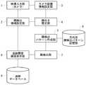
【解決手段】顔検出領域設定部2は、映像から人物の顔領域を検出するための検出領域を設定する。カメラ設置情報設定部3は、カメラの設置位置等の設置パラメータを設定する。顔向き推定部4は、前回検出された顔領域の位置とカメラの設置パラメータを用いて人物の顔の向きを推定する。顔検出パターン作成部5は、顔向き情報を用いて、顔の方向別にあらかじめ用意してある顔検出パターンの集合の中から、次に検出を行う顔の検出パターンを決定する。顔検出部7は、上記の検出領域と顔検出パターンを用いて映像中から人物の顔を検出する。検出された一連の人物の顔画像が同一人物の顔画像の追跡履歴として画面表示される。
【選択図】 図1A person tracking device capable of detecting a face using an appropriate face orientation pattern and creating a highly accurate person tracking result is provided.
A face detection area setting unit 2 sets a detection area for detecting a face area of a person from an image. The camera installation information setting unit 3 sets installation parameters such as a camera installation position. The face orientation estimation unit 4 estimates the face orientation of a person using the previously detected face area position and camera installation parameters. The face detection pattern creating unit 5 uses the face orientation information to determine a face detection pattern to be detected next from a set of face detection patterns prepared in advance for each face direction. The face detection unit 7 detects a human face from the video using the detection area and the face detection pattern. A series of detected face images of a person is displayed on the screen as a tracking history of the face image of the same person.
[Selection] Figure 1
Description
本発明は、監視映像等のビデオ映像から人物の顔を検出して、人物の動きを追跡する人物追跡装置に関するものである。 The present invention relates to a person tracking device that detects a person's face from a video image such as a monitoring image and tracks the movement of the person.
従来、例えばセキュリティ等に有用な情報を提供するために、映像信号を処理して人物を抽出および追跡する人物追跡装置が提案されている。従来の典型的な人物追跡装置は、顔の検出を複数のフレームにおいて連続的に行うことにより人の顔の移動を追跡するように構成されている。また、従来の人物追跡装置は、各フレームにおける顔検出を前回のフレームで顔が検出された領域の近傍のみで行うように構成されている(例えば特許文献1参照)。
しかしながら、従来の人物追跡装置においては、カメラの位置関係を考慮せずに、顔の向きが固定された顔パターンを参照し、この固定された顔パターンと映像を比較して顔を検出していた。その結果、適切な顔パターンが設定されていないために、顔検出が失敗することがあった。そして、顔検出が失敗してしまうと、顔の追跡が途切れてしまい、人物の追跡が失敗するという問題があった。例えば、監視映像等の人物追跡において、画面上に人物が複数人存在して接近している場合や交差した場合に、他人同士を互いに連結してしまうなどの追跡の失敗が発生するという問題があった。 However, in a conventional person tracking device, a face pattern with a fixed face orientation is referenced without considering the positional relationship of the camera, and the face is detected by comparing the fixed face pattern with an image. It was. As a result, face detection may fail because an appropriate face pattern is not set. If face detection fails, face tracking is interrupted and person tracking fails. For example, in tracking a person such as a surveillance video, there is a problem that a tracking failure such as connecting other persons to each other occurs when there are multiple persons on the screen and they are approaching or crossing each other. there were.
特に、監視用途で使用するカメラは上方から撮影するシーンが多く、この場合に撮影される映像は下向き顔になる。しかし、従来はこのような撮像方向が考慮されていないためん、顔検出で取りこぼしてしまうという問題があった。 In particular, a camera used for surveillance purposes has many scenes taken from above, and an image taken in this case has a downward face. However, conventionally, since such an imaging direction is not taken into consideration, there is a problem in that it is missed by face detection.
本発明は、従来の問題を解決するためになされたものであり、その目的は、カメラと人物の位置関係を考慮して、適切な顔向きパターンを用いて顔の検出を行い、高精度な人物追跡結果を作成することのできる人物追跡装置を提供することにある。 The present invention has been made to solve the conventional problems, and its purpose is to detect a face using an appropriate face orientation pattern in consideration of the positional relationship between a camera and a person, and to achieve high accuracy. An object of the present invention is to provide a person tracking device capable of creating a person tracking result.
本発明の人物追跡装置は、カメラで撮影された映像を入力する映像入力手段と、前記映像入力手段で入力された映像から人物の顔領域を検出するための画面上の処理領域である検出領域を設定する顔検出領域設定手段と、前記カメラの設置パラメータを設定するカメラ設置情報設定手段と、前回検出された顔領域の位置と、前記カメラ設置情報設定手段で設定した前記カメラの設置パラメータを用いて、次に検出を行う人物の顔の向きを推定する顔向き推定手段と、前記顔向き推定手段で決定した顔向き情報を用いて、顔の方向別にあらかじめ用意してある顔検出パターンの中から、次に検出を行う顔の検出パターンを決定する顔検出パターン作成手段と、前記顔検出領域設定手段で設定した画面上の検出領域と、前記顔検出パターン作成手段で作成した顔の検出パターンを用いて映像中から人物の顔を検出する顔検出手段と、前記顔検出手段で検出した一連の人物の顔画像を同一人物の顔画像の追跡履歴として画面表示する追跡履歴表示手段を備えている。 The human tracking device according to the present invention includes a video input unit that inputs video captured by a camera, and a detection region that is a processing region on a screen for detecting a human face region from the video input by the video input unit. A face detection area setting means for setting camera installation information setting means for setting camera installation parameters, a position of the face area detected last time, and the camera installation parameters set by the camera installation information setting means. Using face orientation estimating means for estimating the face orientation of a person to be detected next, and face orientation information determined in advance by using the face orientation information determined by the face orientation estimating means. A face detection pattern creation means for determining a face detection pattern to be detected next, a detection area on the screen set by the face detection area setting means, and the face detection pattern creation means The face detection means for detecting a person's face in the video using the face detection pattern created in step 1 and a series of person face images detected by the face detection means are displayed on the screen as the tracking history of the face image of the same person. A tracking history display means is provided.
この構成により、カメラの設置位置等の設置パラメータを用いて映像から人物の顔の向きが推定され、予め用意された顔方向別の顔検出パターンから顔向き情報に応じて顔検出パターンが生成され、この顔検出パターンを用いて映像中から人物の顔が検出される。こうして、カメラと人物の位置関係を考慮して、適切な顔向きパターンを用いて顔の検出を行い、高精度な人物追跡結果を作成することができる。 With this configuration, the orientation of a person's face is estimated from the image using installation parameters such as the installation position of the camera, and a face detection pattern is generated according to the face orientation information from the face detection patterns for each face direction prepared in advance. The face of the person is detected from the video using this face detection pattern. In this way, in consideration of the positional relationship between the camera and the person, it is possible to detect a face using an appropriate face orientation pattern and create a highly accurate person tracking result.
また、本発明の人物追跡装置では、前記顔検出領域設定手段が、直前に人物の顔を検出していない場合は、画面全領域を人物の顔を検出する検出領域として設定するように構成されている。 In the person tracking device of the present invention, the face detection area setting means is configured to set the entire screen area as a detection area for detecting a person's face when the face of the person has not been detected immediately before. ing.
この構成により、人物が画面上の任意の場所に登場した場合でも顔の検出が可能となり、顔検出の失敗を防ぎ、高精度な人物追跡結果を作成することができる。 With this configuration, a face can be detected even when a person appears anywhere on the screen, face detection failure can be prevented, and a highly accurate person tracking result can be created.
また、本発明の人物追跡装置では、前記顔検出領域設定手段が、直前に人物の顔を検出した場合は、直前に検出した顔のサイズと向きの情報から次に検出する顔の検出領域を決定するように構成されている。 In the person tracking device of the present invention, when the face detection area setting unit detects a person's face immediately before, the face detection area to be detected next is detected from information on the size and orientation of the face detected immediately before. Is configured to determine.
この構成により、直前に検出した顔画像と次に検出する顔画像との対応をとることが可能となり、高精度な人物追跡結果を作成することができる。 With this configuration, it is possible to take a correspondence between the face image detected immediately before and the face image detected next, and a highly accurate person tracking result can be created.
また、本発明の人物追跡装置では、前記検出パターン作成手段が、直前に人物の顔を検出していない場合は、顔の正面を中心とした所定の比較的広範囲設定の顔向き範囲の顔パターンを用いて顔の検出パターンを作成するように構成されている。 Further, in the person tracking device of the present invention, when the detection pattern creating means has not detected a person's face immediately before, the face pattern in a predetermined relatively wide face orientation range centered on the front of the face. Is used to create a face detection pattern.
この構成により、人物が監視映像に登場した場合に、顔向きが正面である場合でも、比較的角度の大きい顔向きの場合でも、顔検出の失敗を防ぎ、高精度な人物追跡結果を作成することができる。 With this configuration, when a person appears in a surveillance video, face detection failure is prevented and a highly accurate person tracking result is created regardless of whether the face is facing the front or facing a relatively large angle. be able to.
また、本発明の人物追跡装置では、前記検出パターン作成手段が、直前に人物の顔を検出した場合は、前記顔向き推定手段で決定した顔向きを中心とした範囲の顔パターンを用いて顔の検出パターンを作成するように構成されている。 In the person tracking device of the present invention, when the detection pattern creating unit detects a human face immediately before, a face pattern in the range centered on the face direction determined by the face direction estimating unit is used. Is configured to create a detection pattern.
この構成により、カメラと人物の位置関係を考慮して、適切な顔向きパターンを用いて顔の検出を行い、高精度な人物追跡結果を作成することができる。 With this configuration, it is possible to detect a face using an appropriate face orientation pattern in consideration of the positional relationship between the camera and the person, and to create a highly accurate person tracking result.
本発明の別の態様は、映像を処理して人物を抽出および追跡する人物追跡映像処理方法であり、カメラで撮影された映像を入力し、前記映像から人物の顔領域を検出するための画面上の処理領域である検出領域を設定し、前記カメラの設置パラメータを設定し、前回検出された顔領域の位置と、前記カメラの設置パラメータを用いて、次に検出を行う人物の顔の向きを推定し、推定された顔向き情報を用いて、顔の方向別にあらかじめ用意してある顔検出パターンの中から、次に検出を行う顔の検出パターンを決定し、画面上の前記検出領域と、決定された前記顔の検出パターンを用いて映像中から人物の顔を検出し、検出した一連の人物の顔画像を同一人物の顔画像の追跡履歴として画面表示する。この態様によっても、上述の本発明の利点が得られる。 Another aspect of the present invention is a person tracking image processing method for extracting and tracking a person by processing an image, and a screen for inputting an image taken by a camera and detecting a face area of the person from the image Set the detection area that is the upper processing area, set the installation parameters of the camera, and use the position of the face area detected last time and the installation parameters of the camera, the direction of the face of the person to be detected next Then, using the estimated face orientation information, a face detection pattern to be detected next is determined from face detection patterns prepared in advance for each face direction, and the detection area on the screen is determined. Then, using the determined face detection pattern, a human face is detected from the video, and the detected series of human face images are displayed as a tracking history of the same person's face image. This aspect also provides the above-described advantages of the present invention.
本発明は、監視映像等のビデオ映像において、カメラと人物の位置関係を考慮して、適切な顔向きパターンを用いて顔の検出を行い、高精度な人物追跡結果を作成することのできるという効果を有する人物追跡装置を提供できる。 The present invention can detect a face using an appropriate face orientation pattern in a video image such as a monitoring image in consideration of the positional relationship between a camera and a person, and can create a highly accurate person tracking result. A person tracking device having an effect can be provided.
以下、本発明の実施の形態の人物追跡装置について、図面を用いて説明する。 Hereinafter, a person tracking device according to an embodiment of the present invention will be described with reference to the drawings.
本発明の実施の形態に係る人物追跡装置を図1に示す。 FIG. 1 shows a person tracking apparatus according to an embodiment of the present invention.
図1において、本実施の形態の人物追跡装置は、監視映像等のビデオ映像を撮影するカメラを含み、カメラから出力された映像信号をデジタル画像データ等に変換してパソコン等の処理装置に入力する映像入力部1と、映像入力部1で出力された画像データを入力して、人物の顔領域を検出するための画面上の処理領域である検出領域を設定する顔検出領域設定部2と、映像入力部1で設置されているカメラの高さや取り付け角度、カメラの視野角を含む設置パラメータの設定を行うカメラ設置情報設定部3と、前回検出された顔領域の画面位置とカメラ設置情報設定部3で設定したカメラの設置パラメータから次に検出を行う顔の向きを推定する顔向き推定部4と、顔の様々な方向に対してあらかじめ用意してある複数の顔検出パターンである顔検出パターン集合を記憶した方向別顔検出パターン記憶部6と、顔向き推定部4で決定した顔向き情報を用いて、方向別顔検出パターン記憶部6を参照し、顔検出パターン集合の中から、次に検出を行う顔の検出パターンを決定する顔検出パターン作成部5と、顔検出領域設定部2で設定した検出領域に対して顔検出パターン作成部5で作成した顔検出パターンで人物の顔領域の検出を行う顔検出部7と、顔検出部7で検出した顔領域と前回検出した顔領域との対応をとり、追跡データベース9に格納して、検出した一連の顔画像を同一人物の追跡結果として画面に表示を行う追跡履歴画面表示部8とを有する。
In FIG. 1, the person tracking apparatus according to the present embodiment includes a camera that captures video images such as surveillance images, converts a video signal output from the camera into digital image data and the like, and inputs the digital image data to a processing device such as a personal computer. A video input unit 1 for inputting, and a face detection region setting
以上のように構成された人物追跡装置について、図を用いてその動作を説明する。 The operation of the person tracking device configured as described above will be described with reference to the drawings.
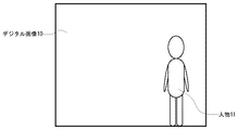
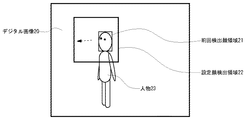
映像入力部1は、リアルタイムに映像が出力される監視カメラ等のデバイスによって構成され、撮影された映像信号が出力される。この映像信号に対して、キャプチャーボード等の映像入力デバイスによって、処理装置へのデータの移動処理および映像信号から図2に示すデジタル画像10(RGBカラー画像)への変換処理等が行われる。なお、本発明の範囲内で、映像入力部1にカメラが含まれなくてよい。映像入力部1は、カメラで撮影された録画映像を入力する構成であってもよい。 The video input unit 1 is configured by a device such as a monitoring camera that outputs video in real time, and a captured video signal is output. The video signal is subjected to a data movement process to the processing device and a conversion process from the video signal to the digital image 10 (RGB color image) shown in FIG. 2 by a video input device such as a capture board. Note that the video input unit 1 may not include a camera within the scope of the present invention. The video input unit 1 may be configured to input a recorded video shot by a camera.
顔検出領域設定部2は、映像入力部1で出力されたデジタル画像10から人物11の顔領域の検出を行うための処理領域である検出領域の設定を行う。本装置の起動時、および直前の一定時間内に人物の顔を検出していない場合は、顔検出領域設定部2は、デジタル画像10の全領域を顔検出の検出領域に設定する。これは、人物が画面内に登場する前であるので、画面内の任意の位置に人物が登場しても対応できるようにするためである。直前の一定時間内に人物の顔を検出した場合は、顔検出領域設定部2は、直前に検出した顔のサイズと向きの情報から顔検出の検出領域を決定する。
The face detection
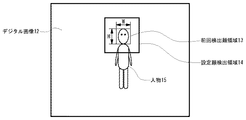
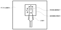
図3は、顔サイズが小さく顔向きがほぼ正面の場合の顔検出領域の設定処理を説明する図である。図4は、顔サイズが大きく顔向きがほぼ正面の場合の顔検出領域の設定処理を説明する図である。図3の前回検出顔領域13および図4の前回検出顔領域17は、直前の処理で検出された顔領域である。前回検出顔領域17は前回検出顔領域13よりも顔サイズが大きい。一般的に、画面上の顔サイズが大きい場合は、単位時間に移動する画面上の移動距離も大きくなる。このため、顔検出領域設定部2は、前回検出した顔領域のサイズが大きければ次に顔を検出する処理領域のサイズ(設定顔検出領域)も大きく設定をする。以上のことから、図4の設定顔検出領域18は図3の設定顔検出領域14よりも大きく設定される。
FIG. 3 is a diagram for explaining a face detection area setting process when the face size is small and the face direction is almost the front. FIG. 4 is a diagram for explaining the face detection area setting process when the face size is large and the face direction is almost the front. The last detected face area 13 in FIG. 3 and the last detected face area 17 in FIG. 4 are face areas detected in the immediately preceding process. The previously detected face area 17 has a larger face size than the previously detected face area 13. In general, when the face size on the screen is large, the moving distance on the screen that moves in unit time also increases. For this reason, if the size of the face area detected last time is large, the face detection
図5は、顔サイズが大きく顔向きが右横向きの場合の顔検出領域の設定処理を説明する図である。図5の前回検出顔領域21は、図4の前回検出顔領域17とほぼ同じサイズと仮定する。この場合、図5の設定顔検出領域22の領域サイズと図4の設定顔検出領域18の領域サイズは同じである。ただし、図5の場合は右方向に顔が向いているため、次に検出される顔領域は画面左方向にずれる可能性が高くなる。そこで、顔検出領域設定部2は、図5の設定顔検出領域22を、前回検出顔領域21の中心から画面左方向にずらして設定する。このずれは、前回検出した顔の向きの大きさに比例して設定される。
FIG. 5 is a diagram for explaining the processing for setting the face detection area when the face size is large and the face orientation is right sideways. It is assumed that the previously detected face area 21 in FIG. 5 is approximately the same size as the previously detected face area 17 in FIG. In this case, the area size of the set face detection area 22 in FIG. 5 and the area size of the set face detection area 18 in FIG. 4 are the same. However, in the case of FIG. 5, since the face is directed to the right, the face area detected next is likely to be shifted to the left on the screen. Therefore, the face detection
このようにして、直前に人物の顔が検出されている場合、顔検出領域設定部2は、(1)直前の人物の顔サイズに応じて、顔サイズが大きいほど検出領域サイズも大きくなるように検出領域を設定し、かつ、(2)直前の人物の顔向きに応じて、前回検出された顔領域の中心から顔向き方向にずれた位置に検出領域を設定し、さらに、(3)顔の向きが大きくなるほど(顔の向きがカメラに対して正面から離れるほど)検出領域のずれ量が大きくなるように検出領域を設定する。 In this way, when a human face is detected immediately before, the face detection area setting unit 2 (1) increases the detection area size as the face size increases according to the face size of the previous person. And (2) a detection area is set at a position shifted from the center of the face area detected last time in the face direction according to the face direction of the immediately preceding person, and (3) The detection area is set so that the displacement amount of the detection area increases as the face direction increases (as the face direction moves away from the front of the camera).
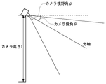
カメラ設置情報設定部3は、映像入力部1のカメラの設置パラメータの設定を装置に対して行う。図6は、カメラの設置パラメータを説明する図である。設置パラメータは、後述する顔向き推定に必要なカメラの設置位置および姿勢とカメラ仕様のパラメータである。本実施の形態では、設置パラメータとして、図6に示すように、カメラの設置高さT、カメラの俯角θ、カメラの視野角φ等を装置に設定する。 The camera installation information setting unit 3 sets the camera installation parameters of the video input unit 1 for the apparatus. FIG. 6 is a diagram illustrating camera installation parameters. The installation parameters are camera installation positions and postures necessary for face orientation estimation, which will be described later, and camera specification parameters. In the present embodiment, as shown in FIG. 6, camera installation height T, camera depression angle θ, camera viewing angle φ, and the like are set in the apparatus as installation parameters.
この設置パラメータの設定は、例えば、カメラが設置されたときに行われる。設置パラメータが、操作者によりキーボード等の入力デバイスを用いて入力されてよい。カメラ設置情報設定部3は、入力された設置パラメータの設定処理を行う。具体的には、設置パラメータが装置内のメモリ等に記憶され、必要に応じて読み出される。また別の例では、カメラに設置パラメータが保持されていてよい。この設置パラメータが映像入力部1からカメラ設置情報設定部3に供給され、装置に設定され、人物追跡のために使用される。この場合、設置パラメータは、必要に応じて任意のタイミングで映像入力部1から取得されてよい。 The setting of the installation parameter is performed when the camera is installed, for example. The installation parameter may be input by an operator using an input device such as a keyboard. The camera installation information setting unit 3 performs setting processing for the input installation parameters. Specifically, the installation parameters are stored in a memory or the like in the apparatus and are read out as necessary. In another example, the installation parameter may be held in the camera. The installation parameters are supplied from the video input unit 1 to the camera installation information setting unit 3, set in the apparatus, and used for person tracking. In this case, the installation parameter may be acquired from the video input unit 1 at an arbitrary timing as necessary.
顔向き推定部4は、前回検出された顔領域の画面位置とカメラ設置情報設定部3で設定したカメラの設置パラメータから次に検出を行う顔の向きを推定する。本実施の形態では、前回と今回での顔向きの変化量が小さいと仮定して、前回検出された顔領域の顔向きが、次に検出を行う顔の向きとして求められる。 The face orientation estimation unit 4 estimates the orientation of the face to be detected next from the screen position of the face area detected last time and the camera installation parameters set by the camera installation information setting unit 3. In the present embodiment, assuming that the amount of change in the face direction between the previous time and the current time is small, the face direction of the face area detected last time is obtained as the face direction to be detected next.
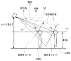
図7は、顔の向きを推定する処理を説明する図である。図7においては、人物A、Bの顔向き算出処理が示されており、添え字a、bは、人物A、Bに対応する。ここでは、まず、添え字a、bを省略して、顔向き算出処理について説明する。 FIG. 7 is a diagram illustrating a process for estimating the face direction. In FIG. 7, the face orientation calculation processing of the persons A and B is shown, and the subscripts a and b correspond to the persons A and B. Here, first, the face orientation calculation process will be described with the subscripts a and b omitted.
図7において、カメラ設置情報設定部3では、カメラの設置高さT、カメラの俯角θ、カメラの視野角φが設定されて既知の値である。この情報と、前回検出された顔領域の中心位置座標Pと、人物の身長Hを用いて、人物の顔向きαが算出される。ここでは、人物が歩行している場合を想定している。 In FIG. 7, the camera installation information setting unit 3 sets the camera installation height T, the camera depression angle θ, and the camera viewing angle φ, which are known values. Using this information, the center position coordinate P of the face area detected last time, and the person's height H, the face orientation α of the person is calculated. Here, it is assumed that a person is walking.
本実施の形態において、人物の身長Hは、通常の頭の上までの高さではなく、顔中心Pまでの高さである。人物の身長Hとしては、人物の平均身長が用いられる。身長Hは、カメラの設置パラメータと共に予め本装置に記憶されていてよい。 In the present embodiment, the height H of the person is not the height up to the normal head, but the height up to the face center P. As the height H of the person, the average height of the person is used. The height H may be stored in advance in this apparatus together with the camera installation parameters.
また、顔中心位置座標Pは、後段の顔検出結果に基づき決定される。例えば顔検出にて両目、鼻および口が抽出され、これら両目、鼻および口を包含する矩形が求められ、この矩形の中心点が顔中心として決定される。 The face center position coordinate P is determined based on the face detection result in the subsequent stage. For example, both eyes, nose and mouth are extracted by face detection, a rectangle including both eyes, nose and mouth is obtained, and the center point of this rectangle is determined as the face center.
本実施の形態では、人物の顔向きαは下記のように定義される。図において、線Lは、カメラと人物の顔中心Pを結ぶ線である。線Lhは、人物の身長Hを通る水平線である。そして、顔向きαは、水平線Lhに対する線Lの角度である。 In the present embodiment, the human face orientation α is defined as follows. In the figure, a line L is a line connecting the camera and the face center P of the person. A line Lh is a horizontal line passing through the height H of the person. The face orientation α is an angle of the line L with respect to the horizontal line Lh.
顔向きαは以下のようにして算出できる。まず、カメラ高さTとカメラ俯角θから、図7のカメラの光軸L0が決定される。次に、光軸L0と視野角φと、映像内の顔中心位置座標Pから、顔中心Pとカメラを結ぶラインLが決定される。ここでは、視野角φを用いて任意の位置に光軸L0に垂直な画像投影面が設定され、顔中心座標Pが投影面上にプロットされ、顔中心座標Pがカメラと結ばれてラインLが得られる。そして、ラインLと水平線Lhの角度が求められる。上記の原理に従ったプログラムが用意され、顔向き推定部4で実行されればよい。 The face orientation α can be calculated as follows. First, the optical axis L0 of the camera in FIG. 7 is determined from the camera height T and the camera depression angle θ. Next, a line L connecting the face center P and the camera is determined from the optical axis L0, the viewing angle φ, and the face center position coordinates P in the video. Here, an image projection plane perpendicular to the optical axis L0 is set at an arbitrary position using the viewing angle φ, the face center coordinate P is plotted on the projection plane, and the face center coordinate P is connected to the camera to form a line L Is obtained. Then, the angle between the line L and the horizontal line Lh is obtained. A program in accordance with the above principle may be prepared and executed by the face direction estimation unit 4.
図7の例では、人物Aの顔向きαaと、人物Bの顔向きαbが算出される。人物Bの方が人物Aよりもカメラに近づいている。そのため、人物Bの顔向きαbの方が人物Aの顔向きαaよりも大きく算出される。 In the example of FIG. 7, the face orientation αa of the person A and the face orientation αb of the person B are calculated. The person B is closer to the camera than the person A. Therefore, the face direction αb of the person B is calculated to be larger than the face direction αa of the person A.
上述の図7では、上下方向の顔向きαが算出された。横方向の顔向きβは以下のように算出される。 In FIG. 7 described above, the face direction α in the vertical direction is calculated. The face direction β in the horizontal direction is calculated as follows.
本実施の形態は、顔が正面を向いているとき(より詳細には、光軸を通る鉛直面に平行な方向を顔が向いているとき)、横方向の顔向きβが0である。そして、顔が真横を向いているとき、横方向の顔向きβが90度である。 In the present embodiment, when the face is facing the front (more specifically, when the face is facing a direction parallel to the vertical plane passing through the optical axis), the lateral face direction β is zero. When the face is facing sideways, the face direction β in the horizontal direction is 90 degrees.
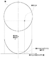
顔向きβを算出するために、顔の法線ベクトルが算出される。ここでは、顔が例えば球体に近似される。球体の中心と顔中心を結ぶベクトルが、顔の法線ベクトルである。まず、顔を円に近似し、円の中での顔中心点(本実施の形態では両目、鼻、口を包含する矩形の中心点)を特定すれば、上記の近似球体面上での顔中心の法線ベクトルが定まる。そして、法線ベクトルの横方向の顔向きβが算出される。顔向きβは、上方から見たときの光軸と法線ベクトルの角度である。より詳細には、法線ベクトルと光軸が、水平面に投影される。水平面上での法線ベクトルと光軸の角度が、横方向の顔向きに相当する。顔向き推定部4では、上記の原理に従ったプログラムが用意され、実行され、これにより顔向きβが算出される。 In order to calculate the face orientation β, a normal vector of the face is calculated. Here, the face is approximated to a sphere, for example. The vector connecting the center of the sphere and the center of the face is the normal vector of the face. First, if the face is approximated to a circle and the face center point in the circle (in this embodiment, the center point of a rectangle including both eyes, nose and mouth) is specified, the face on the above approximate sphere surface The center normal vector is determined. Then, the horizontal face direction β of the normal vector is calculated. The face direction β is an angle between the optical axis and the normal vector when viewed from above. More specifically, the normal vector and the optical axis are projected onto the horizontal plane. The normal vector on the horizontal plane and the angle of the optical axis correspond to the horizontal face orientation. The face orientation estimation unit 4 prepares and executes a program according to the above principle, thereby calculating the face orientation β.
その他、顔向き推定部4は、本装置の起動時、および直前の一定時間内に人物の顔を本装置が検出していない場合には、上下方向および横方向の顔向きを0とする。ここでは、顔向きを判断できないので、後段の処理を適当に行うために、カメラに対して顔が正面を向いているものとして、顔向きを設定する。 In addition, the face direction estimation unit 4 sets the face direction in the vertical direction and the horizontal direction to 0 when the apparatus is activated and when the apparatus has not detected a human face within a certain period of time. Since the face orientation cannot be determined here, the face orientation is set on the assumption that the face is facing the front with respect to the camera in order to appropriately perform the subsequent processing.
図8は、上記のようにして算出される横方向の顔向きβを示している。顔が球体であるとすると、横方向の顔向きβは、球体上の顔中心Pの経度に相当する。したがって、顔中心Pが顔の中で横にずれるほど、顔向きβが大きくなる。 FIG. 8 shows the face direction β in the horizontal direction calculated as described above. If the face is a sphere, the lateral face direction β corresponds to the longitude of the face center P on the sphere. Therefore, the face direction β increases as the face center P shifts laterally in the face.
次に、顔検出パターン作成部5は、顔向き推定部4で決定した顔向き情報を用いて、顔検出パターン集合から、次に検出を行う顔の検出パターンを決定する。顔検出パターン集合は、顔の様々な方向に対してあらかじめ用意してある多数の顔検出パターンからなる。顔検出パターン集合は、方向別顔検出パターン記憶部6に記憶されており、顔検出パターン5により参照される。
Next, the face detection
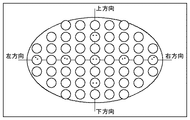
図9は、方向別顔検出パターンを説明する図である。顔向きには、上方向、下方向、右方向、左方向の4方向の向きが存在するため、それぞれの向きに対応した顔検出パターンをマトリクス状に配置してあらかじめ用意しておく。図9における各々の丸い絵が、それぞれの顔向きに対応した顔検出パターンを表している。また、図9の例では、上下方向に最大7つ、左右方向に最大9つの顔検出パターンを配置しているが、この配置間隔はこれよりも多くても少なくても構わない。 FIG. 9 is a diagram illustrating a face detection pattern for each direction. Since there are four directions of the face direction, upward, downward, rightward, and leftward, face detection patterns corresponding to the respective directions are arranged in a matrix and prepared in advance. Each round picture in FIG. 9 represents a face detection pattern corresponding to each face direction. In the example of FIG. 9, a maximum of seven face detection patterns are arranged in the vertical direction and a maximum of nine face detection patterns are arranged in the horizontal direction, but this arrangement interval may be larger or smaller.
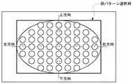
次に顔検出パターンを作成する処理を以下に説明する。本装置の起動時、および直前の一定時間内に人物の顔を検出していない場合は、図10に示すように、図9の全ての方向の顔検出パターンを選択して次に検出を行う顔検出パターンとして設定する。これは、人物が画面内に登場する前なので、画面内に任意の顔向きで人物が登場しても対応できるようにするためである。 Next, processing for creating a face detection pattern will be described below. If the face of a person has not been detected at the time of activation of this apparatus or within a certain period of time immediately before, the face detection patterns in all directions in FIG. 9 are selected and then detected as shown in FIG. Set as face detection pattern. This is because before a person appears on the screen, it is possible to cope with the appearance of a person with any face orientation on the screen.
より詳細には、前述の顔向き推定処理で、本装置の起動時、および直前の一定時間内に人物の顔を検出していない場合、顔の向きは正面に設定されている(顔向きが上下方向に0であり、左右方向にも0である)。この場合、正面方向の顔検出パターン(図10の中央の顔パターン)を中心として顔パターン選択枠が設定される。顔パターン選択枠は、全方向の顔検出パターンを網羅するように広く設定される。そして、この顔パターン選択枠内の顔検出パターンが選択される。こうして、直前に人物の顔を検出していない場合は、顔の正面を中心とした顔向きが比較的広い範囲の顔パターンを用いて顔の検出パターンが作成される。 More specifically, in the face orientation estimation process described above, the face orientation is set to the front (when the face orientation is set) when the face of the person is not detected when the apparatus is started up and within a certain period of time immediately before. 0 in the vertical direction and 0 in the horizontal direction). In this case, a face pattern selection frame is set around the face detection pattern in the front direction (the center face pattern in FIG. 10). The face pattern selection frame is set widely so as to cover face detection patterns in all directions. Then, a face detection pattern within the face pattern selection frame is selected. Thus, when the face of a person has not been detected immediately before, a face detection pattern is created using a face pattern having a relatively wide range of face orientations centered on the front of the face.
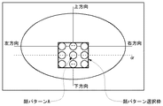
一方、直前の一定時間内に人物の顔を検出した場合は、顔向き推定部4で決定した顔向き情報を用いる。顔向き推定部4で推定された顔向きが上下方向α(α<0)で、左右方向0の場合は、図11に示すように顔パターンAを中心としてその周辺の所定範囲から選択した顔パターン(図11の顔パターン選択枠内の顔検出パターン)のみを次に検出を行う顔検出パターンとして設定する。図11では、選択枠内の顔検出パターンとして、上下方向に3つ、左右方向に3つのパターンを選択しているが、本発明の範囲内でこれよりも多くても少なくても構わない。 On the other hand, when the face of a person is detected within a certain period of time immediately before, the face orientation information determined by the face orientation estimation unit 4 is used. When the face direction estimated by the face direction estimation unit 4 is the vertical direction α (α <0) and the horizontal direction is 0, the face selected from a predetermined range around the face pattern A as shown in FIG. Only the pattern (the face detection pattern in the face pattern selection frame in FIG. 11) is set as the face detection pattern to be detected next. In FIG. 11, three patterns in the vertical direction and three patterns in the horizontal direction are selected as the face detection patterns in the selection frame. However, the number may be more or less within the scope of the present invention.
図11の例では、横方向の顔向きが0である。横方向の顔向きが0でない場合にも同様である。顔向きに対応する位置の顔パターンを中心とする顔パターン選択枠が設定され、選択枠内の顔パターンが選択される。例えば、図11の例で、仮に横方向の顔向きが0でなければ、顔パターン選択枠が横方向へと顔向きと同じ方向にずらされる。 In the example of FIG. 11, the horizontal face direction is zero. The same applies when the horizontal face orientation is not zero. A face pattern selection frame centering on the face pattern at the position corresponding to the face orientation is set, and the face pattern in the selection frame is selected. For example, in the example of FIG. 11, if the face direction in the horizontal direction is not 0, the face pattern selection frame is shifted in the same direction as the face direction in the horizontal direction.
このようにして、顔検出パターン作成部5は、(1)直前に人物の顔を検出していない場合は、図10に示されるように、顔の正面を中心とした顔向きが比較的広い所定の基準範囲の顔パターンを用いて顔の検出パターンを作成し、(2)直前に人物の顔を検出した場合は、図11に示されるように、顔向き推定部4で決定した顔向きを中心とした所定の周辺範囲((1)よりも狭く設定された縮小範囲)の顔向きに対応する顔パターンを選択して顔の検出パターンを作成する。 In this way, the face detection pattern creation unit 5 (1) has a relatively wide face orientation centered on the front of the face as shown in FIG. 10 when the face of a person has not been detected immediately before. When a face detection pattern is created using a face pattern in a predetermined reference range, and (2) a human face is detected immediately before, the face orientation determined by the face orientation estimation unit 4 as shown in FIG. A face detection pattern is created by selecting a face pattern corresponding to the face direction in a predetermined peripheral range centering on (a reduction range set narrower than (1)).
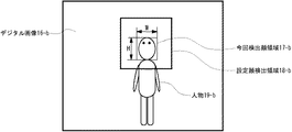
顔検出部7は、顔検出領域設定部2で設定した検出領域に対して顔検出パターン作成部5で作成した顔検出パターンで人物の顔領域の検出を行う。具体例として、顔検出領域設定部2で設定した検出領域が図4の設定顔検出領域18になり、顔検出パターン作成部5で作成した顔検出パターンが図11の顔パターン選択枠内の顔検出パターンになった場合について説明する。図12のデジタル画像16−bは、図4のデジタル画像16の微小時間後の画像とする。この場合、顔検出領域設定部2で設定した顔検出領域は、図12の設定顔検出領域18−bであるので、この領域に対して、顔検出パターン作成部5で作成した図11の顔パターン選択枠内の顔検出パターンを用いて顔検出を行う。この結果、図12の今回検出顔領域17−bが検出される。
The
顔検出処理では、顔検出パターンと映像のパターンマッチングが行われてよい。顔検出パターンとマッチする領域が、人物の顔として検出される。このとき、上述の処理で顔パターン選択枠内から選択された複数の顔検出パターンの各々が映像と比較され、マッチング度が最大の領域が検出されてよい。簡単な例としては、パターンマッチングでは、映像の領域をずらしながら、顔検出パターンと映像の差分が求められる。そして、差分が最小になる領域が探索される。ただし、本発明の範囲内で、顔検出処理は上記に限定されないことはもちろんであり、各種の検出処理が適用可能なことはもちろんである。 In the face detection process, face detection pattern and image pattern matching may be performed. A region that matches the face detection pattern is detected as a human face. At this time, each of the plurality of face detection patterns selected from the face pattern selection frame by the above-described processing may be compared with the video, and an area having the maximum matching degree may be detected. As a simple example, in pattern matching, the difference between the face detection pattern and the video is obtained while shifting the video area. Then, a region where the difference is minimized is searched. However, the face detection process is not limited to the above within the scope of the present invention, and various detection processes can be applied.
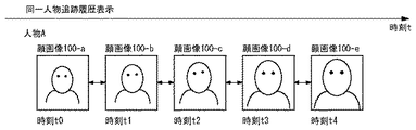
追跡履歴画面表示部8は、顔検出部7で今回検出した顔画像と前回検出した顔画像との対応をとり、顔画像を追跡データベース9に格納して、一連の顔画像を画面に表示する。本実施の形態では、前回検出された顔画像から、上述のようにして今回の検出領域と顔検出パターンが設定されている。追跡履歴画面表示部8は、これら情報を用いて顔画像が検出されたということは、検出された顔画像は前回検出された顔画像と対応すると判断する。具体的には、前回検出を行った画像を図4のデジタル画像16、今回検出した画像を図12のデジタル画像16−bとすると、図4の前回検出顔画像17と図12の今回検出顔画像17−bが同一人物として対応がとれ、追跡データベース9に同一人物として格納される。このようにして次々と対応する顔画像が検出され、追跡データベースには、同一人物毎に時系列の顔画像が保存される。この時系列に保存された一連の顔画像は、画面に表示をして確認することができるようにする。図13は、同一人物の追跡履歴を画面表示した例を説明する図である。このように、同一人物に対して、時系列に顔画像100−a、100−b、100−c、100−d、100−eを画面に表示する。
The tracking history
追跡履歴画面表示部8までの処理を行った場合は、顔検出領域設定部2の処理に戻り、上記説明の処理を繰り返して、人物の追跡を行い、追跡データベース9に追跡結果の蓄積を継続する。
When the processing up to the tracking history
以上に、本発明の実施の形態に係る人物追跡装置について説明した。本実施の形態によれば、上述のように、カメラの設置位置等の設置パラメータを用いて映像から人物の顔の向きが推定され、予め用意された顔方向別の顔検出パターンから顔向き情報に応じて顔検出処理で使用する顔検出パターンが作成され、この顔検出パターンを用いて映像中から人物の顔が検出される。こうして、カメラと人物の位置関係を考慮して、適切な顔向きパターンを用いて顔の検出を行い、高精度な人物追跡結果を作成することができる。 The person tracking apparatus according to the embodiment of the present invention has been described above. According to the present embodiment, as described above, the orientation of a person's face is estimated from the video using the installation parameters such as the installation position of the camera, and the face orientation information is obtained from the face detection patterns for each face direction prepared in advance. Accordingly, a face detection pattern used in the face detection process is created, and the face of the person is detected from the video using the face detection pattern. In this way, in consideration of the positional relationship between the camera and the person, it is possible to detect a face using an appropriate face orientation pattern and create a highly accurate person tracking result.
また、本実施の形態によれば、直前に人物の顔を検出していない場合は、画面全領域が人物の顔を検出する検出領域として設定される。これにより、人物が画面上の任意の場所に登場した場合でも顔の検出が可能となり、顔検出の失敗を防ぎ、高精度な人物追跡結果を作成することができる。 Further, according to the present embodiment, when a person's face is not detected immediately before, the entire screen area is set as a detection area for detecting a person's face. This makes it possible to detect a face even when a person appears anywhere on the screen, prevent face detection failure, and create a highly accurate person tracking result.
また、本実施の形態によれば、直前に人物の顔を検出した場合は、直前に検出した顔のサイズと向きの情報から次に検出する顔の検出領域が決定される。これにより、直前に検出した顔画像と次に検出する顔画像との対応をとることが可能となり、高精度な人物追跡結果を作成することができる。 Further, according to the present embodiment, when a human face is detected immediately before, a face detection area to be detected next is determined from information on the size and orientation of the face detected immediately before. As a result, it is possible to take correspondence between the face image detected immediately before and the face image detected next, and a highly accurate person tracking result can be created.
また、本実施の形態によれば、直前に人物の顔を検出していない場合は、顔の正面を中心とした所定の比較的広範囲設定の顔向き範囲の顔パターンを用いて顔の検出パターンが作成される。これにより、人物が監視映像に登場した場合に、顔向きが正面である場合でも、比較的角度の大きい顔向きの場合でも、顔検出の失敗を防ぎ、高精度な人物追跡結果を作成することができる。 Further, according to the present embodiment, when a human face has not been detected immediately before, a face detection pattern using a face pattern in a predetermined relatively wide face orientation range centered on the front of the face is used. Is created. This prevents face detection failures and creates highly accurate person tracking results when a person appears in a surveillance video, regardless of whether the face is facing the front or a face with a relatively large angle. Can do.
また、本実施の形態によれば、直前に人物の顔を検出した場合は、顔向き推定処理で決定した顔向きを中心とした範囲の顔パターンを用いて顔の検出パターンが作成される。これにより、カメラと人物の位置関係を考慮して、適切な顔向きパターンを用いて顔の検出を行い、高精度な人物追跡結果を作成することができる。 Further, according to the present embodiment, when a human face is detected immediately before, a face detection pattern is created using a face pattern in a range centered on the face orientation determined by the face orientation estimation process. This makes it possible to detect a face using an appropriate face orientation pattern in consideration of the positional relationship between the camera and the person, and to create a highly accurate person tracking result.
以上に本発明の好適な実施の形態を説明した。しかし、本発明は上述の実施の形態に限定されず、当業者が本発明の範囲内で上述の実施の形態を変形可能なことはもちろんである。 The preferred embodiments of the present invention have been described above. However, the present invention is not limited to the above-described embodiments, and it goes without saying that those skilled in the art can modify the above-described embodiments within the scope of the present invention.
以上のように、本発明にかかる人物追跡装置は、監視映像等のビデオ映像において、カメラと人物の位置関係を考慮して、適切な顔向きパターンを用いて顔の検出を行い、高精度な人物追跡結果を作成することができるという効果を有し、人物の行動を監視する用途や人物の検索を行うためのデータベースを構築する人物追跡装置等として有用である。 As described above, the human tracking device according to the present invention detects a face using an appropriate face orientation pattern in a video image such as a monitoring image in consideration of the positional relationship between the camera and the person, and has high accuracy. It has the effect that a person tracking result can be created, and is useful as a person tracking device for constructing a database for searching for a person or a purpose for monitoring a person's behavior.
1 映像入力部
2 顔検出領域設定部
3 カメラ設置情報設定部
4 顔向き推定部
5 顔検出パターン作成部
6 方向別顔検出パターン記憶部
7 顔検出部
8 追跡履歴画面表示部
9 追跡データベース部
DESCRIPTION OF SYMBOLS 1 Image |
Claims (6)
前記映像入力手段で入力された映像から人物の顔領域を検出するための画面上の処理領域である検出領域を設定する顔検出領域設定手段と、
前記カメラの設置パラメータを設定するカメラ設置情報設定手段と、
前回検出された顔領域の位置と、前記カメラ設置情報設定手段で設定した前記カメラの設置パラメータを用いて、次に検出を行う人物の顔の向きを推定する顔向き推定手段と、
前記顔向き推定手段で決定した顔向き情報を用いて、顔の方向別にあらかじめ用意してある顔検出パターンの中から、次に検出を行う顔の検出パターンを決定する顔検出パターン作成手段と、
前記顔検出領域設定手段で設定した画面上の検出領域と、前記顔検出パターン作成手段で作成した顔の検出パターンを用いて映像中から人物の顔を検出する顔検出手段と、
前記顔検出手段で検出した一連の人物の顔画像を同一人物の顔画像の追跡履歴として画面表示する追跡履歴表示手段を備えたことを特徴とする人物追跡装置。 Video input means for inputting video captured by the camera;
Face detection area setting means for setting a detection area which is a processing area on a screen for detecting a human face area from the video input by the video input means;
Camera installation information setting means for setting the installation parameters of the camera;
A face direction estimating means for estimating the face direction of a person to be detected next, using the position of the face area detected last time and the camera installation parameters set by the camera installation information setting means;
Using the face orientation information determined by the face orientation estimating means, a face detection pattern creating means for determining a face detection pattern to be detected next from face detection patterns prepared in advance for each face direction;
A detection area on the screen set by the face detection area setting means, and a face detection means for detecting a human face in the video using the face detection pattern created by the face detection pattern creation means;
A person tracking apparatus comprising tracking history display means for displaying a series of person face images detected by the face detecting means on the screen as a tracking history of face images of the same person.
前記映像から人物の顔領域を検出するための画面上の処理領域である検出領域を設定し、
前記カメラの設置パラメータを設定し、
前回検出された顔領域の位置と、前記カメラの設置パラメータを用いて、次に検出を行う人物の顔の向きを推定し、
推定された顔向き情報を用いて、顔の方向別にあらかじめ用意してある顔検出パターンの中から、次に検出を行う顔の検出パターンを決定し、
画面上の前記検出領域と、決定された前記顔の検出パターンを用いて映像中から人物の顔を検出し、
検出した一連の人物の顔画像を同一人物の顔画像の追跡履歴として画面表示することを特徴とする人物追跡映像処理方法。 Enter the video shot with the camera,
Set a detection area that is a processing area on the screen for detecting a human face area from the video,
Set the installation parameters of the camera,
Using the position of the face area detected last time and the installation parameters of the camera, the direction of the face of the person to be detected next is estimated,
Using the estimated face orientation information, a face detection pattern to be detected next is determined from face detection patterns prepared in advance for each face direction,
Detecting a human face from the video using the detection area on the screen and the determined face detection pattern,
A person tracking video processing method characterized in that a series of detected face images of a person is displayed on the screen as a tracking history of the face image of the same person.
Priority Applications (1)
| Application Number | Priority Date | Filing Date | Title |
|---|---|---|---|
| JP2006181403A JP2008009849A (en) | 2006-06-30 | 2006-06-30 | Person tracking device |
Applications Claiming Priority (1)
| Application Number | Priority Date | Filing Date | Title |
|---|---|---|---|
| JP2006181403A JP2008009849A (en) | 2006-06-30 | 2006-06-30 | Person tracking device |
Publications (1)
| Publication Number | Publication Date |
|---|---|
| JP2008009849A true JP2008009849A (en) | 2008-01-17 |
Family
ID=39067975
Family Applications (1)
| Application Number | Title | Priority Date | Filing Date |
|---|---|---|---|
| JP2006181403A Pending JP2008009849A (en) | 2006-06-30 | 2006-06-30 | Person tracking device |
Country Status (1)
| Country | Link |
|---|---|
| JP (1) | JP2008009849A (en) |
Cited By (13)
| Publication number | Priority date | Publication date | Assignee | Title |
|---|---|---|---|---|
| JP2010022601A (en) * | 2008-07-18 | 2010-02-04 | Omron Corp | Monitoring device, method, and program |
| JP2011029737A (en) * | 2009-07-22 | 2011-02-10 | Hitachi Kokusai Electric Inc | Surveillance image retrieval apparatus and surveillance system |
| JP2011191987A (en) * | 2010-03-15 | 2011-09-29 | Omron Corp | Reporting device and reporting system |
| JP2011193198A (en) * | 2010-03-15 | 2011-09-29 | Omron Corp | Monitoring camera terminal |
| JP2013042514A (en) * | 2012-09-21 | 2013-02-28 | Omron Corp | Target image detection device, control method therefor, control program, recording medium with the program recorded thereon, and electronic apparatus provided with target image detection device |
| EP2237552A3 (en) * | 2009-04-03 | 2014-01-01 | FUJIFILM Corporation | Autofocus system |
| US9189683B2 (en) | 2008-03-14 | 2015-11-17 | Omron Corporation | Target image detection device, controlling method of the same, control program and recording medium recorded with program, and electronic apparatus equipped with target image detection device |
| JP2017033132A (en) * | 2015-07-30 | 2017-02-09 | パナソニックIpマネジメント株式会社 | Face authentication apparatus |
| WO2018168042A1 (en) * | 2017-03-14 | 2018-09-20 | オムロン株式会社 | Image analysis device, image analysis method, and image analysis program |
| JP2019037004A (en) * | 2018-11-26 | 2019-03-07 | キヤノン株式会社 | Image processing apparatus, control method thereof, and program |
| US10475237B2 (en) | 2014-09-26 | 2019-11-12 | Canon Kabushiki Kaisha | Image processing apparatus and control method thereof |
| CN112419637A (en) * | 2019-08-22 | 2021-02-26 | 北京奇虎科技有限公司 | Security image data processing method and device |
| JP7132392B1 (en) * | 2021-05-12 | 2022-09-06 | レノボ・シンガポール・プライベート・リミテッド | Electronic device and control method |
-
2006
- 2006-06-30 JP JP2006181403A patent/JP2008009849A/en active Pending
Cited By (19)
| Publication number | Priority date | Publication date | Assignee | Title |
|---|---|---|---|---|
| US9189683B2 (en) | 2008-03-14 | 2015-11-17 | Omron Corporation | Target image detection device, controlling method of the same, control program and recording medium recorded with program, and electronic apparatus equipped with target image detection device |
| JP2010022601A (en) * | 2008-07-18 | 2010-02-04 | Omron Corp | Monitoring device, method, and program |
| EP2237552A3 (en) * | 2009-04-03 | 2014-01-01 | FUJIFILM Corporation | Autofocus system |
| JP2011029737A (en) * | 2009-07-22 | 2011-02-10 | Hitachi Kokusai Electric Inc | Surveillance image retrieval apparatus and surveillance system |
| JP2011191987A (en) * | 2010-03-15 | 2011-09-29 | Omron Corp | Reporting device and reporting system |
| JP2011193198A (en) * | 2010-03-15 | 2011-09-29 | Omron Corp | Monitoring camera terminal |
| JP2013042514A (en) * | 2012-09-21 | 2013-02-28 | Omron Corp | Target image detection device, control method therefor, control program, recording medium with the program recorded thereon, and electronic apparatus provided with target image detection device |
| US10475237B2 (en) | 2014-09-26 | 2019-11-12 | Canon Kabushiki Kaisha | Image processing apparatus and control method thereof |
| JP2017033132A (en) * | 2015-07-30 | 2017-02-09 | パナソニックIpマネジメント株式会社 | Face authentication apparatus |
| WO2018168042A1 (en) * | 2017-03-14 | 2018-09-20 | オムロン株式会社 | Image analysis device, image analysis method, and image analysis program |
| JP2018151919A (en) * | 2017-03-14 | 2018-09-27 | オムロン株式会社 | Image analysis apparatus, image analysis method, and image analysis program |
| US11188781B2 (en) | 2017-03-14 | 2021-11-30 | Omron Corporation | Image analyzer, image analysis method, and image analysis program |
| JP2019037004A (en) * | 2018-11-26 | 2019-03-07 | キヤノン株式会社 | Image processing apparatus, control method thereof, and program |
| CN112419637A (en) * | 2019-08-22 | 2021-02-26 | 北京奇虎科技有限公司 | Security image data processing method and device |
| CN112419637B (en) * | 2019-08-22 | 2024-05-14 | 北京奇虎科技有限公司 | Security image data processing method and device |
| JP7132392B1 (en) * | 2021-05-12 | 2022-09-06 | レノボ・シンガポール・プライベート・リミテッド | Electronic device and control method |
| CN115344110A (en) * | 2021-05-12 | 2022-11-15 | 联想(新加坡)私人有限公司 | Electronic device and control method |
| US12148243B2 (en) | 2021-05-12 | 2024-11-19 | Lenovo (Singapore) Pte. Ltd. | Electronic apparatus and control method |
| CN115344110B (en) * | 2021-05-12 | 2026-04-03 | 联想(新加坡)私人有限公司 | Electronic devices and control methods |
Similar Documents
| Publication | Publication Date | Title |
|---|---|---|
| JP3279479B2 (en) | Video monitoring method and device | |
| JP4991595B2 (en) | Tracking system using particle filter | |
| US10769798B2 (en) | Moving object detection apparatus, moving object detection method and program | |
| JP4586709B2 (en) | Imaging device | |
| JP4373840B2 (en) | Moving object tracking method, moving object tracking program and recording medium thereof, and moving object tracking apparatus | |
| GB2516173A (en) | Tracking assistance device, tracking assistance system and tracking assistance method | |
| US20040141633A1 (en) | Intruding object detection device using background difference method | |
| JP5001930B2 (en) | Motion recognition apparatus and method | |
| JP2012243161A (en) | Image processing apparatus and image processing method | |
| JP2008009849A (en) | Person tracking device | |
| CN102369549A (en) | Device for creating information for positional estimation of matter, method for creating information for positional estimation of matter, and program | |
| US20220004748A1 (en) | Video display method, device and system, and video camera | |
| EP3624443B1 (en) | Surveillance device, surveillance method, computer program, and storage medium | |
| JP4559874B2 (en) | Motion tracking device | |
| JP5253227B2 (en) | Image input device, subject detection method, and program | |
| KR102344227B1 (en) | Moving body detecting device, moving body detecting method, and moving body detecting program | |
| KR20190026625A (en) | Image displaying method, Computer program and Recording medium storing computer program for the same | |
| JP2017147689A (en) | Video editing apparatus, video editing method, and video editing computer program | |
| JP7524713B2 (en) | Information processing device and information processing method | |
| JP6405606B2 (en) | Image processing apparatus, image processing method, and image processing program | |
| JP2006033188A (en) | Monitoring device and monitoring method | |
| US20120165084A1 (en) | Method and apparatus for tracking locations using webcams | |
| JP2004128648A (en) | Intruding object tracking method | |
| JP2018190132A (en) | Computer program for image recognition, image recognition apparatus and image recognition method | |
| JP3980341B2 (en) | Eye position tracking method, eye position tracking device and program therefor |
Legal Events
| Date | Code | Title | Description |
|---|---|---|---|
| A521 | Request for written amendment filed |
Free format text: JAPANESE INTERMEDIATE CODE: A523 Effective date: 20071122 |