JP5168220B2 - Image forming apparatus - Google Patents
Image forming apparatus Download PDFInfo
- Publication number
- JP5168220B2 JP5168220B2 JP2009101874A JP2009101874A JP5168220B2 JP 5168220 B2 JP5168220 B2 JP 5168220B2 JP 2009101874 A JP2009101874 A JP 2009101874A JP 2009101874 A JP2009101874 A JP 2009101874A JP 5168220 B2 JP5168220 B2 JP 5168220B2
- Authority
- JP
- Japan
- Prior art keywords
- image
- memory
- image data
- input
- memory section
- Prior art date
- Legal status (The legal status is an assumption and is not a legal conclusion. Google has not performed a legal analysis and makes no representation as to the accuracy of the status listed.)
- Expired - Fee Related
Links
Images


Description
本発明は、メモリの利用効率を向上させた画像形成装置に関する。 The present invention relates to an image forming apparatus with improved memory utilization efficiency.
画像処理装置に搭載しているメモリは、画像データを格納するのに使用する他、画像データを編集する時などに用いられる。また、画像データの種類によってメモリへの格納の仕方が異なる。 The memory mounted on the image processing apparatus is used not only for storing image data but also for editing image data. Further, the method of storing in the memory differs depending on the type of image data.
そのため、メモリに格納するデータのサイズやデータを格納する頻度は、メモリの利用目的によって異なり、場合によっては、メモリの利用効率が悪くなってしまう。 For this reason, the size of data to be stored in the memory and the frequency of storing the data vary depending on the purpose of use of the memory, and in some cases, the efficiency of use of the memory is deteriorated.
そこで、メモリを予め区分けしておくことで、メモリを使用する際に区分けされた領域のみを使用する技術が既に知られている。 In view of this, there is already known a technique that uses only a divided area when the memory is used by dividing the memory in advance.
図11は、従来の画像処理装置における利用目的毎のメモリ区分を示す模式図である。 FIG. 11 is a schematic diagram showing memory division for each purpose of use in a conventional image processing apparatus.
システム領域90には、プログラムなどの処理を行うために用いられ、ソフトウェア群がHDDから読み出した各プログラムが転送される。
The
プリンタ画像領域91には、画像データが格納される。印刷処理において蓄積印刷を行う場合の画像データや圧縮データはこの区分に格納される。
Image data is stored in the
スタンプ領域92には、スタンプデータが格納される。このスタンプデータは、画像データにスタンプを載せる時のデータとして使用される。
Stamp data is stored in the
回転領域93は、画像データを回転する際に使用される。
The
コピー画像領域94には、コピー画像が格納される。印刷処理において蓄積印刷を行う場合のコピーの画像データはこの区分に格納される。
A copy image is stored in the
スキャナ画像領域95には、スキャナから読み取った画像が格納される。
The
フォーマット変換領域96は、スキャナ画像のフォーマットを別のフォーマットに変換する際に使用される。
The
関連する技術として特許文献1には、メモリの利用効率を高める目的で、画像データの付加情報を基に、カラー画像かモノクロ画像かを判断し、メモリの利用区分を切り替える技術が開示されている。 As a related technique, Patent Document 1 discloses a technique for determining whether a color image or a monochrome image is based on additional information of image data and switching a memory use category for the purpose of improving the use efficiency of the memory. .
しかしながら、図11に示すようなメモリを区分する方法では、設定された区分を後で変更することを想定していない。 However, the method for partitioning the memory as shown in FIG. 11 does not assume that the set partition is changed later.
そのため、大きなデータサイズの画像データを扱う画像処理装置では、画像データを格納するための区分が大きく、他の目的に利用するためのメモリを小さくしているため、他の目的に利用するためのメモリが足りなくなり、該目的のためのデータが扱えなくなるといった問題があった。 Therefore, in an image processing apparatus that handles image data of a large data size, the division for storing the image data is large, and the memory for use for other purposes is reduced, so that it is used for other purposes. There is a problem that the memory is insufficient and data for the purpose cannot be handled.
そこで本発明は、メモリ区分があらかじめ設定されている場合であっても、適切に、大きなデータサイズの画像データを扱うことが可能な画像形成装置を提供することを目的とする。 SUMMARY An advantage of some aspects of the invention is that it provides an image forming apparatus capable of appropriately handling image data having a large data size even when memory divisions are set in advance .
上記目的を達成するため、本発明が提供する画像形成装置は、画像データを蓄積する蓄積手段と、画像データに基づいて画像形成する画像形成手段と、原稿の画像を読み取って画像データとして前記蓄積手段に入力する第1の入力手段と、外部装置から受信した画像データを前記蓄積手段に入力する第2の入力手段と、メモリの使用用途毎の使用可能領域を区分けするための複数のメモリ区分情報を格納する第1の記憶手段と、使用される機能に応じて、前記メモリ区分情報を参照してメモリの使用用途毎の使用可能領域を区分けするメモリ区分手段と、を備え、前記メモリ区分手段は、前記第1の入力手段から入力された画像データと前記第2の入力手段から入力された画像データとが混在する複数の画像データの画像形成が行われるとき、画像形成の速度が優先される場合は、前記複数のメモリ区分情報にかかわらず、前記蓄積手段からの画像処理用のメモリ区分である第1のメモリ区分を、前記使用可能領域として区分けし、前記画像形成手段は、第1のメモリ区分を使用して、前記第1の入力手段から入力された画像データと前記第2の入力手段から入力された画像データとが混在する複数の画像データの画像形成を行うことを特徴とする。 In order to achieve the above object, an image forming apparatus provided by the present invention includes an accumulating unit that accumulates image data, an image forming unit that forms an image based on the image data, and the accumulating unit that reads an image of an original as image data. A first input means for inputting to the means; a second input means for inputting the image data received from the external device to the storage means; and a plurality of memory sections for partitioning the usable area for each usage of the memory first storage means for storing information, depending on the function to be used, the by referring to the memory section information includes a memory section means for dividing the available area for each intended use of the memory, wherein the memory section The means is configured to perform image formation of a plurality of image data in which the image data input from the first input means and the image data input from the second input means are mixed. When priority is given to the speed of image formation, regardless of the plurality of pieces of memory division information, the first memory division, which is a memory division for image processing from the storage means, is divided as the usable area, and The image forming means uses the first memory section, and uses a plurality of image data in which image data input from the first input means and image data input from the second input means are mixed. It is characterized by forming .
本発明によれば、メモリ区分があらかじめ設定されている場合であっても、適切に、大きなデータサイズの画像データを扱うことが可能な画像形成装置を提供することが可能とする。 According to the present invention, it is possible to provide an image forming apparatus capable of appropriately handling image data having a large data size even when memory classification is set in advance .
次に、発明を実施するための最良の形態について図面を参照して詳細に説明する。 Next, the best mode for carrying out the invention will be described in detail with reference to the drawings.
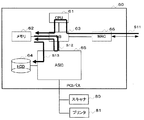
図1は、本発明の実施形態における画像処理装置1の構成図を示す。画像処理装置1は、ソフトウェア群2と、起動部3と、ハードウェア資源4と、を有して構成される。
FIG. 1 is a configuration diagram of an image processing apparatus 1 according to an embodiment of the present invention. The image processing apparatus 1 includes a
起動部3は、画像処理装置1の電源投入時に処理を実行し、ソフトウェア群2を起動する。具体的には、起動部3は、ソフトウェア群2を、外部記憶手段に対応するハードディスク装置(以下、HDDという)などから読み出し、読み出した各プログラムをメモリ領域に転送して起動する。
The
ハードウェア資源4は、エンジン7、メモリ13と、その他ハードウェア資源14とを含む。また、エンジン7は、プリンタ11と、スキャナ12とを含む。
The
ソフトウェア群2は、アプリケーション層5とプラットフォーム6とを含む。ソフトウェア群2の各ソフトウェアは、UNIX(登録商標)などのオペレーティングシステム(以下、OSという)上で、プロセスとして並列実行される。
The
アプリケーション層5は、プリンタ用のアプリケーションであるプリンタアプリ21と、コピー用アプリケーションであるコピーアプリ22と、スキャナ用アプリケーションであるスキャナアプリ23とを含む。各アプリケーションは、画像処理にかかるユーザサービスに対する固有の処理を行う。
The
プラットフォーム6は、アプリケーション層5からの処理要求を解釈してエンジン7の獲得要求を発生するコントロールサービス層9と、コントロールサービス層9からの獲得要求を調停するシステムリソースマネージャ(以下、SRMという)38と、メモリ13を管理するイメージメモリハンドラ(以下、IMHという)41とを含む。アプリケーション層5が必要とする処理は、プラットフォーム6で一元的に実施することが可能である。
The platform 6 interprets a processing request from the
コントロールサービス層9は、ネットワークコントロールサービス(以下、NCSという)31、デリバリーコントロールサービス(以下、DCSという)32、オペレーションパネルコントロールサービス(以下、OCSという)33、エンジンコントロールサービス(以下、ECSという)34、メモリコントロールサービス(以下、MCSという)35、ユーザインフォメーションコントロールサービス(以下、UCSという)36、システムコントロールサービス(以下、SCSという)37などを含む。 The control service layer 9 includes a network control service (hereinafter referred to as NCS) 31, a delivery control service (hereinafter referred to as DCS) 32, an operation panel control service (hereinafter referred to as OCS) 33, and an engine control service (hereinafter referred to as ECS) 34. , A memory control service (hereinafter referred to as MCS) 35, a user information control service (hereinafter referred to as UCS) 36, a system control service (hereinafter referred to as SCS) 37, and the like.
NCS31は、ネットワークI/Oを必要とするアプリケーションに対して共通に利用できるサービスを提供するものであり、ネットワーク側から各プロトコルによって受信したデータを各アプリケーションへの振り分けや、各アプリケーションからのデータをネットワーク側に送信する際の仲介を行う。 The NCS 31 provides a service that can be used in common for applications that require network I / O. Data received from the network side according to each protocol is distributed to each application, and data from each application is distributed. Mediates when sending to the network side.
例えばNCS31は、ネットワークを介して接続されるネットワーク機器とのデータ通信をhttpd(Hyper Text Transfer Protocol Daemon)により、HTTP(Hyper Text Transfer Protocol)で制御する。 For example, the NCS 31 controls data communication with a network device connected via a network by HTTP (Hyper Text Transfer Protocol Daemon) by HTTP (Hyper Text Transfer Protocol).
DCS32は、蓄積文書の配信などの制御を行う。 The DCS 32 performs control such as distribution of stored documents.
OCS33は、オペレータと本体制御との間の情報伝達手段となるオペレーションパネルの制御を行う。 The OCS 33 controls an operation panel serving as information transmission means between the operator and the main body control.
ECS34は、エンジン7の制御を行う。
The ECS 34 controls the
MCS35は、IMH41を利用して、メモリの取得および開放、HDDの利用などの制御を行う。
The MCS 35 uses the
UCS36は、ユーザ情報の管理を行う。 The UCS 36 manages user information.
SCS37は、アプリケーション管理、操作部制御、システム画面表示、LED表示、割り込みアプリケーション制御などの処理を行う。 The SCS 37 performs processing such as application management, operation unit control, system screen display, LED display, and interrupt application control.
SRM38は、エンジン7を利用する上位層からの獲得要求に従って調停を行う。具体的なプロセスは、上位層からの獲得要求に対してハードウェア資源4を利用するためのスケジューリングを行い、要求内容(例えば、プリンタエンジンによる紙搬送と作像動作、メモリ確保、ファイル生成など)を直接実施している。
The SRM 38 performs arbitration according to an acquisition request from a higher layer that uses the
IMH41は、プロセスに対するメモリの割り振り及びプロセスに割り振ったメモリの管理を行う。
The
図2は、画像処理装置1のハードウェア構成を示す図である。画像処理装置1は、コントローラ60と、スキャナ80、プリンタ81とを含む。
FIG. 2 is a diagram illustrating a hardware configuration of the image processing apparatus 1. The image processing apparatus 1 includes a
コントローラ60は、CPU61と、メモリ62と、ノースブリッジ(以下、NBという)63と、HDD64と、ASIC65と、MAC66とを含む。
The
エンジン部80は、コントローラ60のASIC65にPCIバスで接続されている。
The
コントローラ60では、ASIC65にHDD64などが接続されると共に、CPU61とASIC65とがNB63を介して接続されている。
In the
CPU61は、ソフトウェア群2をプロセスとして起動して実行する。
The
メモリ62は、画像処理装置1の描画用記憶手段などとして用いられる。
The
NB63は、CPU61、メモリ62、ASIC65、およびASIC65を接続するためのブリッジである。
The
MAC66は、周辺デバイスの1つでイーサーネット通信を制御する。
The
オペレーションパネル70は、コントローラ60のASIC65に接続されている。オペレーションパネル70には、アプリケーション選択ボタンが存在し、そのボタンを選択すると、選択したアプリケーションが実行される。
The
図3は、PCからの画像データをHDDに蓄積する際のプリントデータ蓄積時のフローを説明する図である。 FIG. 3 is a diagram for explaining a flow at the time of storing print data when image data from the PC is stored in the HDD.
PCから送出された画像データは、MAC66、NB63、CPU61を経由してメモリ62に作像される(ステップS11)。
The image data sent from the PC is imaged in the
作像された画像データは、ASIC65により圧縮され、圧縮された圧縮データがメモリ62に格納される(ステップS12)。
The formed image data is compressed by the
メモリ62に格納された圧縮データは、HDD64に格納される(ステップS13)。
The compressed data stored in the
次に、図4を参照してスキャナから読み取った画像をHDDに蓄積する際のコピーデータ蓄積時のフローを説明する。 Next, a flow at the time of storing copy data when an image read from the scanner is stored in the HDD will be described with reference to FIG.
スキャナ80にて読み取った画像データは、スキャナ80、NB63を経由してメモリ62に格納される(ステップS21)。
The image data read by the
メモリ62に一時格納された画像データは、その後HDD64に格納される(ステップS22)。
The image data temporarily stored in the
次に、図5を参照してHDDに蓄積されている画像を印刷する際の蓄積データ印刷時のフローを説明する。 Next, a flow at the time of printing stored data when printing an image stored in the HDD will be described with reference to FIG.
HDD64に格納されている画像データ、または圧縮データをメモリ62に格納する(ステップS31)。
Image data or compressed data stored in the
ステップS31にてメモリ62に格納した画像データ、または圧縮データをプリンタ31に転送する(ステップS32)。
In step S31, the image data or the compressed data stored in the
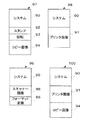
図6は、本発明の実施形態における利用目的毎に区分けしたメモリ区分の模式図である。 FIG. 6 is a schematic diagram of the memory division divided for each purpose of use in the embodiment of the present invention.
コピー用メモリ区分97は、システム領域90と、スタンプ領域92と、回転領域93と、コピー画像領域94と、に区分けされ、コピーを行う時に使用される。
The
プリンタ用メモリ区分98は、システム領域90と、プリンタ画像領域91と、に区分けされ、画像データを印刷する際に使用される。
The
スキャナ用メモリ区分99は、システム領域90と、スキャナ画像領域96と、フォーマット画像領域95と、に区分けされ、スキャナを用いて画像データを取り込む際に使用される。
The
蓄積印刷用メモリ区分100は、システム90領域と、プリンタ画像91領域と、コピー画像94領域と、に区分けされ、蓄積印刷を行う際に使用される。
The storage
図6に示すような実行する機能毎のメモリの区分情報は、予め不揮発性メモリなどに格納されており、実行する機能によって、格納されている区分情報に従ってメモリが区分けされる。 The memory division information for each function to be executed as shown in FIG. 6 is stored in advance in a non-volatile memory or the like, and the memory is divided according to the stored division information by the function to be executed.
図7は、メモリ区分の切替フローを示す模式図である。 FIG. 7 is a schematic diagram showing a memory segment switching flow.
オペレーションパネル70には、アプリケーション選択ボタンである「コピー」「プリンタ」「スキャン」「蓄積」が備えられ、利用者がボタンを押すと(ステップS41)、それぞれ、コピーアプリ22、プリンタアプリ21、スキャンアプリ23、コピーアプリ22が実行される。
The
プリンタを実行した場合、プリンタアプリ21がSCS37、SRM38を経由して、IMH41に対してプリンタ用のメモリマップを使用することを指示する(ステップS42)。
When the printer is executed, the
コピーを実行した場合には、コピーアプリ21がSCS37、SRM38を経由して、IMH1に対してコピー用のメモリマップを使用することを指示する。また、蓄積印刷を実行する場合には、コピーアプリ21がIMH41に対して、後述する設定情報に従って選択されるメモリマップを使用することを指示する(ステップS43)。
When copying is executed, the
スキャナを実行した場合は、スキャナアプリ23がSCS37、SRM38を経由して、IMH41に対してスキャナ用のメモリマップを使用することを指示する(ステップS44)。
When the scanner is executed, the
ところで、HDDには、蓄積印刷(HDDに蓄積された画像を印刷出力する)できる文書が格納されているが、その文書がプリンタ蓄積(PCからの画像をHDDに蓄積)により格納された文書なのか、コピー蓄積(スキャナからの画像をHDDに蓄積)により格納された文書なのかにより、使用するメモリ区分に違いが発生する。 By the way, the HDD stores a document that can be stored and printed (prints and outputs the image stored in the HDD), but the document is a document stored by printer storage (images from the PC are stored in the HDD). Depending on whether the document is stored by copy accumulation (images from the scanner are accumulated in the HDD), a difference occurs in the memory classification to be used.
これは、一般的にプリンタ画像のサイズが、コピー画像のサイズよりも大きいためである。そのため、プリンタ画像の場合には、画像を格納する区分のサイズを大きくとる必要があり、編集用のメモリ区分が存在するコピー用のメモリ区分では、画像を格納できない可能性がある。その結果プリンタ画像は編集が行えず、そのまま出力するのみとなる。 This is because the size of the printer image is generally larger than the size of the copy image. Therefore, in the case of a printer image, it is necessary to increase the size of the section for storing the image, and there is a possibility that the image cannot be stored in the copy memory section where the editing memory section exists. As a result, the printer image cannot be edited and is simply output as it is.
一方、サイズが小さいコピー画像の場合には、編集用のメモリ区分が存在するコピー用のメモリ区分を使用することにより、蓄積されたコピー画像を出力する際にスタンプや回転等の編集を行うことができる。 On the other hand, in the case of a copy image with a small size, by using a copy memory section in which an edit memory section exists, editing such as stamp and rotation is performed when the accumulated copy image is output. Can do.
そこで、蓄積された画像がコピー画像なのかプリンタ画像なのかに応じてメモリ区分を切り替えなければ、ユーザが所望する画像処理ができないことになる。 Therefore, unless the memory division is switched according to whether the stored image is a copy image or a printer image, the image processing desired by the user cannot be performed.
そこで、本実施形態では、蓄積用メモリ区分を使用して印刷する場合に、プリンタ画像(PCから入力されてHDDに蓄積された文書)なのかコピー画像(スキャナから入力されてHDDに蓄積された文書)なのかを判別することで生産性を向上させる。 Therefore, in this embodiment, when printing is performed using the storage memory section, it is a printer image (a document input from a PC and stored in the HDD) or a copy image (input from a scanner and stored in the HDD). Productivity is improved by determining whether it is a document.
例えば、ユーザにより蓄積画像(文書)を複数選択して出力を行うときに、その複数文書のなかにプリンタ画像と、コピー画像と、が混在している場合、プリンタ用メモリ区分及びコピー用メモリ区分を切り替えて使用すると、文書ごとに当該文書に対応したメモリ区分に切替えなければならず、時間がかかることになる。(最初にコピー画像を全て出力してからプリンタ画像を全て出力するように制御した場合であっても、少なくとも1回は切替えが発生する)。 For example, when the user selects and outputs a plurality of stored images (documents), if the printer image and the copy image are mixed in the plurality of documents, the printer memory section and the copy memory section When switching and using, it is necessary to switch to the memory section corresponding to the document for each document, which takes time. (Even if the control is performed so that all the copy images are output first and then all the printer images are output, switching occurs at least once).
一方、本実施形態で示す蓄積用メモリ区分を使用すれば、コピー画像と、プリンタ画像と、でメモリ区分の切り替えを行わずに所望する画像処理(画像編集)を行うことができる。 On the other hand, if the storage memory section shown in this embodiment is used, desired image processing (image editing) can be performed between the copy image and the printer image without switching the memory section.
図8は、蓄積用メモリ区分使用時のフローを示す模式図である。 FIG. 8 is a schematic diagram showing a flow when the storage memory section is used.
ユーザは、後述する設定情報をオペレーションパネル70を使用して不揮発性メモリ68に設定する(ステップS51)。なお、設定情報とは、蓄積用メモリ区分を使用して画像処理を行う際に、処理を行う画像データがプリンタ画像か、あるいはコピー画像か、によって切り替えられるメモリの容量に関する情報である。
The user sets setting information to be described later in the
プリンタを実行して、画像データをHDD64に蓄積した場合、プリンタアプリ21は、蓄積した画像がプリンタ画像であることを示す識別情報とともに画像データをHDD64に蓄積する(ステップS52)。
When the printer is executed and the image data is stored in the
コピーを実行して、画像データをHDD64に蓄積した場合、コピーアプリ22は、蓄積した画像がコピー画像であることを示す識別情報とともに画像データをHDD64に蓄積する。
When copying is performed and image data is stored in the
続いて、不揮発性メモリ68に設定される蓄積画像印刷時に使用するメモリ区分について詳細に説明する。ユーザは、オペレーションパネル70を使用して設定情報を不揮発性メモリに格納する。
Next, the memory classification used when printing the stored image set in the
格納される設定情報としては、例えば、「速度優先」か、「機能優先」か、によって設定される。具体的には、「機能優先」の場合は、機能が優先され、コピーの画像に対して編集を行うことが可能であり、図6のコピー用メモリ区分95に示すようにスタンプ、回転用の区分が存在する。一方、「速度優先」は、編集を行う必要がなく、スピード優先で印刷を行いたい場合などに用いられ、図6の蓄積印刷用メモリ区分98に示すように、スタンプ、回転用の区分が存在しない。
The setting information to be stored is set by, for example, “speed priority” or “function priority”. Specifically, in the case of “function priority”, the function is prioritized and the copy image can be edited. As shown in the
「速度優先」では、図6で示す蓄積印刷用のメモリ区分100のようにメモリ領域を区分けする。
In “speed priority”, the memory area is divided like the
一方、「機能優先」では、図6で示すコピー用メモリ区分97、またはプリンタ用メモリ区分98のようにメモリ領域を区分けする。
On the other hand, in “function priority”, the memory area is divided like the
具体的には、「機能優先」の場合には、蓄積画像に付加されている識別情報を基に、コピーアプリ22は、IMH41に対してコピー用メモリ区分97、またはプリンタ用メモリ区分98のようにメモリの区分切り替えを指示するため、コピー画像とプリンタ画像を同時に印刷するような場合、メモリ切替を指示する時間だけ印刷時間が増加する。
Specifically, in the case of “function priority”, based on the identification information added to the stored image, the
一方、「速度優先」の場合、コピー画像とプリンタ画像を同時に印刷するような場合でも、メモリ区分の切り替え指示を行うことなく、蓄積印刷用のメモリ区分100のようにメモリ領域を最初に区切るだけで良いため、余分な時間を必要としない。
On the other hand, in the case of “speed priority”, even when a copy image and a printer image are printed at the same time, the memory area is first partitioned as in the
図9は、本発明の実施形態における情報処理装置の蓄積印刷時におけるフローチャート図である。 FIG. 9 is a flowchart at the time of accumulation printing of the information processing apparatus according to the embodiment of the present invention.
ユーザにより、オペレーションパネル70の「蓄積」ボタンと、印刷方法(速度優先か機能優先か)と、印刷する蓄積画像と、が選択されると、コピーアプリ22を実行し(ステップS61)、「速度優先」の印刷か、「機能優先」の印刷か、を判断する(ステップS62)。
When the user selects an “Accumulate” button on the
「機能優先」であれば、ユーザにより「印刷開始」ボタンが押されると、印刷する蓄積画像に付加されている識別情報を取得し(ステップS63)、識別情報より、プリンタ画像かコピー画像かを判断する(ステップS64)。 If “function priority” is selected, when the user presses the “print start” button, identification information added to the stored image to be printed is acquired (step S63), and the printer image or copy image is determined from the identification information. Judgment is made (step S64).
プリンタ画像であれば、IMH41に対して「プリンタ用のメモリ区分」を使用するように通知して設定を行い(ステップS65)、印刷を行う(ステップS69)。ユーザにより選択された全てのデータを印刷したか否かを判断し(ステップS70)、残っているデータがあれば、ステップS63からの処理を繰り返す。
If it is a printer image, the
一方、ステップS64の判断にてコピー画像と判断されれば、IMH41に対して「コピー用のメモリ区分」を使用するように通知して設定を行い(ステップS66)、オペレーションパネル70などを通じてユーザに編集を行うかを問い合わせる(ステップS67)。
On the other hand, if the copy image is determined in step S64, the
編集が行われるよう指示を受けた場合には、該指示に従って編集を行った後に(ステップS68)、印刷を行う(ステップS69)。ユーザにより選択された全てのデータを印刷したか否かを判断し(ステップS70)、残っているデータがあれば、ステップS63からの処理を繰り返す。 When an instruction to perform editing is received, editing is performed according to the instruction (step S68), and then printing is performed (step S69). It is determined whether or not all data selected by the user has been printed (step S70), and if there is remaining data, the processing from step S63 is repeated.
また、ステップS62の判断にて「速度優先」と判断されれば、ユーザにより「印刷開始」ボタンが押されると、コピーアプリ22は、IMH41に対して蓄積印刷用のメモリ区分を使用するよう通知して設定する(ステップS71)。
If “speed priority” is determined in step S62, when the user presses the “print start” button, the
蓄積印刷用のメモリ区分を用いて印刷を行い(ステップS72)、ユーザにより選択された全てのデータを印刷したか否かを判断し(ステップS73)、全てのデータを印刷したと判断できるまで印刷を行う。 Printing is performed using the memory category for accumulated printing (step S72), it is determined whether all data selected by the user has been printed (step S73), and printing is performed until it can be determined that all data has been printed. I do.
なお、ステップS67における編集の問い合わせは、予めユーザから指定された画像データを印刷するときにのみ問い合わせるようにしても良い。あるいは、コピー画像と判断された全データについて、自動で同一の編集を行うようにしても良い。また、印刷実行前に選択された全てのデータの識別情報から全ての画像データの種類を判断し、コピー画像がない場合には、予め編集不可である旨を通知するようにしても良い。 The editing inquiry in step S67 may be inquired only when image data designated in advance by the user is printed. Alternatively, the same editing may be automatically performed on all data determined to be copy images. Also, the type of all image data may be determined from the identification information of all data selected before printing, and if there is no copy image, it may be notified in advance that editing is not possible.
図10は、本発明の実施形態における情報処理装置の蓄積印刷時におけるメモリ区分の切り替えを示す模式図である。 FIG. 10 is a schematic diagram showing switching of memory sections during storage printing of the information processing apparatus according to the embodiment of the present invention.
まず、蓄積印刷用メモリ区分として区分けされた領域に対してプリンタ画像91の領域サイズを小さくする(ステップS81)。
First, the area size of the
スタンプ92領域を確保し(ステップS82)、スタンプ92の領域をシステム90の領域とプリンタ画像90の領域の間に配置する(ステップS83)。
The area of the
本発明の実施形態によれば、利用者が指定した情報に基づいて、メモリの利用区分を動的に切替えることで、また、利用者がメモリの利用区分を選択できるようにすることで、今まで以上にメモリの利用効率を高め、また、利用者が、メモリの利用効率を高めた結果発生する制約を選択することが出来る。 According to the embodiment of the present invention, it is possible to dynamically change the memory usage category based on information specified by the user, and to enable the user to select the memory usage category. Thus, the memory utilization efficiency can be further improved, and the user can select a constraint that occurs as a result of the memory utilization efficiency being increased.
以上、実施の形態を説明したが、特許請求の範囲に定義された本発明の広範囲な趣旨および範囲から逸脱することなく、これら実施の形態や具体例に様々な修正および変更が可能である。 Although the embodiments have been described above, various modifications and changes can be made to these embodiments and specific examples without departing from the broad scope and scope of the present invention defined in the claims.
1 画像処理装置
2 ソフトウェア群
3 起動部
4 ハードウェア資源
60 コントローラ
70 オペレーションパネル
80 スキャナ
81 プリンタ
DESCRIPTION OF SYMBOLS 1
Claims (3)
画像データに基づいて画像形成する画像形成手段と、
原稿の画像を読み取って画像データとして前記蓄積手段に入力する第1の入力手段と、
外部装置から受信した画像データを前記蓄積手段に入力する第2の入力手段と、
メモリの使用用途毎の使用可能領域を区分けするための複数のメモリ区分情報を格納する第1の記憶手段と、
使用される機能に応じて、前記メモリ区分情報を参照してメモリの使用用途毎の使用可能領域を区分けするメモリ区分手段と、を備え、
前記メモリ区分手段は、
前記第1の入力手段から入力された画像データと前記第2の入力手段から入力された画像データとが混在する複数の画像データの画像形成が行われるとき、
画像形成の速度が優先される場合は、
前記複数のメモリ区分情報にかかわらず、前記蓄積手段からの画像処理用のメモリ区分である第1のメモリ区分を、前記使用可能領域として区分けし、
前記画像形成手段は、第1のメモリ区分を使用して、前記第1の入力手段から入力された画像データと前記第2の入力手段から入力された画像データとが混在する複数の画像データの画像形成を行う
ことを特徴とする画像形成装置。 Storage means for storing image data;
Image forming means for forming an image based on the image data;
First input means for reading an image of a document and inputting it as image data to the storage means;
Second input means for inputting image data received from an external device to the storage means;
First storage means for storing a plurality of pieces of memory classification information for dividing usable areas for each usage of memory;
According to a function to be used, memory partitioning means for partitioning an available area for each usage of the memory with reference to the memory partition information ,
The memory partitioning means is
When image formation of a plurality of image data in which the image data input from the first input unit and the image data input from the second input unit are mixed is performed,
If speed of image formation is a priority,
Regardless of the plurality of memory partition information, a first memory partition that is a memory partition for image processing from the storage means is partitioned as the usable area,
The image forming means uses a first memory section to store a plurality of image data in which image data input from the first input means and image data input from the second input means are mixed. An image forming apparatus that performs image formation .
前記第1の入力手段から入力された画像データと前記第2の入力手段から入力された画像データとが混在する複数の画像データの画像形成が行われるとき、 When image formation of a plurality of image data in which the image data input from the first input unit and the image data input from the second input unit are mixed is performed,
画像形成の機能が優先される場合は、 If priority is given to the image forming function,
前記第1の入力手段から入力された画像データの画像処理用のメモリ区分である第2のメモリ区分と、前記第2の入力手段から入力された画像データの画像処理用のメモリ区分である第3のメモリ区分とを、それぞれ前記使用可能領域として区分けし、 A second memory section that is a memory section for image processing of image data input from the first input means, and a second memory section that is a memory section for image processing of image data input from the second input means. Each of the three memory sections as the usable area,
前記画像形成手段は、前記第2のメモリ区分と前記第3のメモリ区分とを、切り替えて使用して、前記第1の入力手段から入力された画像データと前記第2の入力手段から入力された画像データとが混在する複数の画像データの画像形成を行う The image forming means switches between the second memory section and the third memory section and uses the image data input from the first input means and the second input means. Image formation with multiple image data
ことを特徴とする請求項1記載の画像形成装置。 The image forming apparatus according to claim 1.
前記画像形成装置は、画像データの画像形成の際、前記識別情報に基づいて前記第2又は第3のメモリ区分を切り替えて使用する The image forming apparatus switches and uses the second or third memory section based on the identification information when forming image data.
ことを特徴とする請求項2記載の画像形成装置。 The image forming apparatus according to claim 2.
Priority Applications (1)
| Application Number | Priority Date | Filing Date | Title |
|---|---|---|---|
| JP2009101874A JP5168220B2 (en) | 2009-04-20 | 2009-04-20 | Image forming apparatus |
Applications Claiming Priority (1)
| Application Number | Priority Date | Filing Date | Title |
|---|---|---|---|
| JP2009101874A JP5168220B2 (en) | 2009-04-20 | 2009-04-20 | Image forming apparatus |
Publications (2)
| Publication Number | Publication Date |
|---|---|
| JP2010252234A JP2010252234A (en) | 2010-11-04 |
| JP5168220B2 true JP5168220B2 (en) | 2013-03-21 |
Family
ID=43314035
Family Applications (1)
| Application Number | Title | Priority Date | Filing Date |
|---|---|---|---|
| JP2009101874A Expired - Fee Related JP5168220B2 (en) | 2009-04-20 | 2009-04-20 | Image forming apparatus |
Country Status (1)
| Country | Link |
|---|---|
| JP (1) | JP5168220B2 (en) |
Family Cites Families (2)
| Publication number | Priority date | Publication date | Assignee | Title |
|---|---|---|---|---|
| JP2004347630A (en) * | 2003-05-19 | 2004-12-09 | Ricoh Co Ltd | Digital compound machine |
| JP2009038771A (en) * | 2007-08-03 | 2009-02-19 | Ricoh Co Ltd | Image processor and image processing method |
-
2009
- 2009-04-20 JP JP2009101874A patent/JP5168220B2/en not_active Expired - Fee Related
Also Published As
| Publication number | Publication date |
|---|---|
| JP2010252234A (en) | 2010-11-04 |
Similar Documents
| Publication | Publication Date | Title |
|---|---|---|
| JP3740379B2 (en) | Image processing apparatus and image processing method | |
| JP3692757B2 (en) | Image forming apparatus and control method thereof | |
| JP4769661B2 (en) | Image processing device | |
| JP2002084383A (en) | Apparatus and method for image formation and program | |
| US7016066B2 (en) | Image output control apparatus, image output control method, and storage medium, for selecting between first and second output modes | |
| JP3977286B2 (en) | Image conversion service method and image conversion apparatus | |
| JP4859103B2 (en) | Image forming apparatus | |
| US20100228931A1 (en) | Management apparatus, system, control method, and recording medium | |
| JP5664324B2 (en) | Distributed printing system, image forming apparatus, method, and program | |
| US20080165375A1 (en) | Image-processing control device | |
| JP3768463B2 (en) | Image forming apparatus that cooperates between apparatuses via a network | |
| JP6690513B2 (en) | Information processing apparatus, information processing system, and information processing method | |
| JP2007221180A (en) | Control method of image forming apparatus, control program of image forming apparatus, and image forming apparatus | |
| JP5168220B2 (en) | Image forming apparatus | |
| JP2006180496A (en) | Image forming apparatus associating with other apparatuses through network | |
| JP2008079247A (en) | Image forming apparatus | |
| JPH11122417A (en) | Picture formation system and information processor in the system and method for controlling the same | |
| JP4157376B2 (en) | Information processing apparatus, image forming apparatus, control method, and program | |
| JP4027711B2 (en) | Network printing system and management method thereof | |
| JP2000311071A (en) | Output controller, output control method, and storage medium stored with computer readable program | |
| JP5538334B2 (en) | Image forming apparatus and job control program | |
| JP2020110926A (en) | Image formation apparatus, control method of image formation apparatus, image formation system and program | |
| JP3257136B2 (en) | Image processing device | |
| JP4960269B2 (en) | Image processing system and image processing apparatus | |
| JP2004341996A (en) | Task control for printing processing |
Legal Events
| Date | Code | Title | Description |
|---|---|---|---|
| A621 | Written request for application examination |
Free format text: JAPANESE INTERMEDIATE CODE: A621 Effective date: 20120228 |
|
| A977 | Report on retrieval |
Free format text: JAPANESE INTERMEDIATE CODE: A971007 Effective date: 20120725 |
|
| A131 | Notification of reasons for refusal |
Free format text: JAPANESE INTERMEDIATE CODE: A131 Effective date: 20120814 |
|
| A521 | Written amendment |
Free format text: JAPANESE INTERMEDIATE CODE: A523 Effective date: 20121015 |
|
| TRDD | Decision of grant or rejection written | ||
| A01 | Written decision to grant a patent or to grant a registration (utility model) |
Free format text: JAPANESE INTERMEDIATE CODE: A01 Effective date: 20121127 |
|
| A61 | First payment of annual fees (during grant procedure) |
Free format text: JAPANESE INTERMEDIATE CODE: A61 Effective date: 20121210 |
|
| R151 | Written notification of patent or utility model registration |
Ref document number: 5168220 Country of ref document: JP Free format text: JAPANESE INTERMEDIATE CODE: R151 |
|
| FPAY | Renewal fee payment (event date is renewal date of database) |
Free format text: PAYMENT UNTIL: 20160111 Year of fee payment: 3 |
|
| LAPS | Cancellation because of no payment of annual fees |