JP5167254B2 - Joining three objects using friction stir processing technology - Google Patents
Joining three objects using friction stir processing technology Download PDFInfo
- Publication number
- JP5167254B2 JP5167254B2 JP2009515503A JP2009515503A JP5167254B2 JP 5167254 B2 JP5167254 B2 JP 5167254B2 JP 2009515503 A JP2009515503 A JP 2009515503A JP 2009515503 A JP2009515503 A JP 2009515503A JP 5167254 B2 JP5167254 B2 JP 5167254B2
- Authority
- JP
- Japan
- Prior art keywords
- pin
- consumable
- friction stir
- tool
- workpieces
- Prior art date
- Legal status (The legal status is an assumption and is not a legal conclusion. Google has not performed a legal analysis and makes no representation as to the accuracy of the status listed.)
- Active
Links
- 238000003756 stirring Methods 0.000 title claims abstract description 59
- 238000012545 processing Methods 0.000 title claims description 8
- 238000005304 joining Methods 0.000 title description 11
- 239000000463 material Substances 0.000 claims abstract description 103
- 238000005520 cutting process Methods 0.000 claims abstract description 16
- 238000009792 diffusion process Methods 0.000 claims abstract description 7
- 238000000034 method Methods 0.000 claims description 44
- 230000007246 mechanism Effects 0.000 claims description 18
- 230000000149 penetrating effect Effects 0.000 claims description 2
- 238000003466 welding Methods 0.000 description 28
- 230000008569 process Effects 0.000 description 19
- 230000008018 melting Effects 0.000 description 9
- 238000002844 melting Methods 0.000 description 9
- 229910000831 Steel Inorganic materials 0.000 description 8
- 230000008901 benefit Effects 0.000 description 8
- 239000007787 solid Substances 0.000 description 8
- 239000010959 steel Substances 0.000 description 8
- 229910052751 metal Inorganic materials 0.000 description 7
- 239000002184 metal Substances 0.000 description 7
- 229910052782 aluminium Inorganic materials 0.000 description 5
- XAGFODPZIPBFFR-UHFFFAOYSA-N aluminium Chemical compound [Al] XAGFODPZIPBFFR-UHFFFAOYSA-N 0.000 description 5
- 229910000601 superalloy Inorganic materials 0.000 description 5
- PXHVJJICTQNCMI-UHFFFAOYSA-N Nickel Chemical compound [Ni] PXHVJJICTQNCMI-UHFFFAOYSA-N 0.000 description 4
- 238000010438 heat treatment Methods 0.000 description 4
- 229910001220 stainless steel Inorganic materials 0.000 description 4
- 239000010935 stainless steel Substances 0.000 description 4
- RTAQQCXQSZGOHL-UHFFFAOYSA-N Titanium Chemical compound [Ti] RTAQQCXQSZGOHL-UHFFFAOYSA-N 0.000 description 3
- 238000013459 approach Methods 0.000 description 3
- 239000010953 base metal Substances 0.000 description 3
- 230000007547 defect Effects 0.000 description 3
- 230000004927 fusion Effects 0.000 description 3
- 235000019589 hardness Nutrition 0.000 description 3
- 238000003754 machining Methods 0.000 description 3
- 230000035515 penetration Effects 0.000 description 3
- 239000010936 titanium Substances 0.000 description 3
- 229910052719 titanium Inorganic materials 0.000 description 3
- XKRFYHLGVUSROY-UHFFFAOYSA-N Argon Chemical compound [Ar] XKRFYHLGVUSROY-UHFFFAOYSA-N 0.000 description 2
- 229910052582 BN Inorganic materials 0.000 description 2
- PZNSFCLAULLKQX-UHFFFAOYSA-N Boron nitride Chemical compound N#B PZNSFCLAULLKQX-UHFFFAOYSA-N 0.000 description 2
- 229910000906 Bronze Inorganic materials 0.000 description 2
- CURLTUGMZLYLDI-UHFFFAOYSA-N Carbon dioxide Chemical compound O=C=O CURLTUGMZLYLDI-UHFFFAOYSA-N 0.000 description 2
- 229910000531 Co alloy Inorganic materials 0.000 description 2
- 229910000640 Fe alloy Inorganic materials 0.000 description 2
- CWYNVVGOOAEACU-UHFFFAOYSA-N Fe2+ Chemical compound [Fe+2] CWYNVVGOOAEACU-UHFFFAOYSA-N 0.000 description 2
- ZOKXTWBITQBERF-UHFFFAOYSA-N Molybdenum Chemical compound [Mo] ZOKXTWBITQBERF-UHFFFAOYSA-N 0.000 description 2
- 238000010521 absorption reaction Methods 0.000 description 2
- 239000010974 bronze Substances 0.000 description 2
- KUNSUQLRTQLHQQ-UHFFFAOYSA-N copper tin Chemical compound [Cu].[Sn] KUNSUQLRTQLHQQ-UHFFFAOYSA-N 0.000 description 2
- 230000007797 corrosion Effects 0.000 description 2
- 238000005260 corrosion Methods 0.000 description 2
- 238000009826 distribution Methods 0.000 description 2
- 239000012530 fluid Substances 0.000 description 2
- 239000007788 liquid Substances 0.000 description 2
- 239000007791 liquid phase Substances 0.000 description 2
- 239000011156 metal matrix composite Substances 0.000 description 2
- 238000012986 modification Methods 0.000 description 2
- 230000004048 modification Effects 0.000 description 2
- 229910052750 molybdenum Inorganic materials 0.000 description 2
- 239000011733 molybdenum Substances 0.000 description 2
- 229910052702 rhenium Inorganic materials 0.000 description 2
- WUAPFZMCVAUBPE-UHFFFAOYSA-N rhenium atom Chemical compound [Re] WUAPFZMCVAUBPE-UHFFFAOYSA-N 0.000 description 2
- 239000007790 solid phase Substances 0.000 description 2
- 238000007711 solidification Methods 0.000 description 2
- 230000008023 solidification Effects 0.000 description 2
- 230000009466 transformation Effects 0.000 description 2
- WFKWXMTUELFFGS-UHFFFAOYSA-N tungsten Chemical compound [W] WFKWXMTUELFFGS-UHFFFAOYSA-N 0.000 description 2
- 229910052721 tungsten Inorganic materials 0.000 description 2
- 239000010937 tungsten Substances 0.000 description 2
- VYZAMTAEIAYCRO-UHFFFAOYSA-N Chromium Chemical compound [Cr] VYZAMTAEIAYCRO-UHFFFAOYSA-N 0.000 description 1
- 229910000885 Dual-phase steel Inorganic materials 0.000 description 1
- 229910000997 High-speed steel Inorganic materials 0.000 description 1
- 229910001030 Iron–nickel alloy Inorganic materials 0.000 description 1
- PWHULOQIROXLJO-UHFFFAOYSA-N Manganese Chemical compound [Mn] PWHULOQIROXLJO-UHFFFAOYSA-N 0.000 description 1
- 229910000990 Ni alloy Inorganic materials 0.000 description 1
- 206010057430 Retinal injury Diseases 0.000 description 1
- 229910000794 TRIP steel Inorganic materials 0.000 description 1
- 230000009471 action Effects 0.000 description 1
- 238000013019 agitation Methods 0.000 description 1
- 239000003570 air Substances 0.000 description 1
- 229910045601 alloy Inorganic materials 0.000 description 1
- 239000000956 alloy Substances 0.000 description 1
- 229910052786 argon Inorganic materials 0.000 description 1
- 230000000712 assembly Effects 0.000 description 1
- 238000000429 assembly Methods 0.000 description 1
- 230000015572 biosynthetic process Effects 0.000 description 1
- 229910002092 carbon dioxide Inorganic materials 0.000 description 1
- 239000001569 carbon dioxide Substances 0.000 description 1
- 229910052804 chromium Inorganic materials 0.000 description 1
- 239000011651 chromium Substances 0.000 description 1
- JOPOVCBBYLSVDA-UHFFFAOYSA-N chromium(6+) Chemical compound [Cr+6] JOPOVCBBYLSVDA-UHFFFAOYSA-N 0.000 description 1
- 239000011248 coating agent Substances 0.000 description 1
- 238000000576 coating method Methods 0.000 description 1
- 239000002131 composite material Substances 0.000 description 1
- 238000013461 design Methods 0.000 description 1
- 229910003460 diamond Inorganic materials 0.000 description 1
- 239000010432 diamond Substances 0.000 description 1
- 239000007789 gas Substances 0.000 description 1
- 230000005802 health problem Effects 0.000 description 1
- 239000011261 inert gas Substances 0.000 description 1
- 229910052741 iridium Inorganic materials 0.000 description 1
- GKOZUEZYRPOHIO-UHFFFAOYSA-N iridium atom Chemical compound [Ir] GKOZUEZYRPOHIO-UHFFFAOYSA-N 0.000 description 1
- UGKDIUIOSMUOAW-UHFFFAOYSA-N iron nickel Chemical compound [Fe].[Ni] UGKDIUIOSMUOAW-UHFFFAOYSA-N 0.000 description 1
- 229910052748 manganese Inorganic materials 0.000 description 1
- 239000011572 manganese Substances 0.000 description 1
- 238000010297 mechanical methods and process Methods 0.000 description 1
- 239000003595 mist Substances 0.000 description 1
- 229910052759 nickel Inorganic materials 0.000 description 1
- 229910052758 niobium Inorganic materials 0.000 description 1
- 239000010955 niobium Substances 0.000 description 1
- GUCVJGMIXFAOAE-UHFFFAOYSA-N niobium atom Chemical compound [Nb] GUCVJGMIXFAOAE-UHFFFAOYSA-N 0.000 description 1
- 230000003647 oxidation Effects 0.000 description 1
- 238000007254 oxidation reaction Methods 0.000 description 1
- 230000008439 repair process Effects 0.000 description 1
- 230000035945 sensitivity Effects 0.000 description 1
- 239000002195 soluble material Substances 0.000 description 1
- 229910052715 tantalum Inorganic materials 0.000 description 1
- GUVRBAGPIYLISA-UHFFFAOYSA-N tantalum atom Chemical compound [Ta] GUVRBAGPIYLISA-UHFFFAOYSA-N 0.000 description 1
- 238000000844 transformation Methods 0.000 description 1
- XLYOFNOQVPJJNP-UHFFFAOYSA-N water Substances O XLYOFNOQVPJJNP-UHFFFAOYSA-N 0.000 description 1
- 230000003245 working effect Effects 0.000 description 1
Images


Classifications
-
- B—PERFORMING OPERATIONS; TRANSPORTING
- B23—MACHINE TOOLS; METAL-WORKING NOT OTHERWISE PROVIDED FOR
- B23K—SOLDERING OR UNSOLDERING; WELDING; CLADDING OR PLATING BY SOLDERING OR WELDING; CUTTING BY APPLYING HEAT LOCALLY, e.g. FLAME CUTTING; WORKING BY LASER BEAM
- B23K20/00—Non-electric welding by applying impact or other pressure, with or without the application of heat, e.g. cladding or plating
- B23K20/12—Non-electric welding by applying impact or other pressure, with or without the application of heat, e.g. cladding or plating the heat being generated by friction; Friction welding
- B23K20/122—Non-electric welding by applying impact or other pressure, with or without the application of heat, e.g. cladding or plating the heat being generated by friction; Friction welding using a non-consumable tool, e.g. friction stir welding
- B23K20/123—Controlling or monitoring the welding process
-
- B—PERFORMING OPERATIONS; TRANSPORTING
- B23—MACHINE TOOLS; METAL-WORKING NOT OTHERWISE PROVIDED FOR
- B23K—SOLDERING OR UNSOLDERING; WELDING; CLADDING OR PLATING BY SOLDERING OR WELDING; CUTTING BY APPLYING HEAT LOCALLY, e.g. FLAME CUTTING; WORKING BY LASER BEAM
- B23K20/00—Non-electric welding by applying impact or other pressure, with or without the application of heat, e.g. cladding or plating
- B23K20/12—Non-electric welding by applying impact or other pressure, with or without the application of heat, e.g. cladding or plating the heat being generated by friction; Friction welding
- B23K20/122—Non-electric welding by applying impact or other pressure, with or without the application of heat, e.g. cladding or plating the heat being generated by friction; Friction welding using a non-consumable tool, e.g. friction stir welding
- B23K20/1245—Non-electric welding by applying impact or other pressure, with or without the application of heat, e.g. cladding or plating the heat being generated by friction; Friction welding using a non-consumable tool, e.g. friction stir welding characterised by the apparatus
- B23K20/1255—Tools therefor, e.g. characterised by the shape of the probe
-
- B—PERFORMING OPERATIONS; TRANSPORTING
- B23—MACHINE TOOLS; METAL-WORKING NOT OTHERWISE PROVIDED FOR
- B23K—SOLDERING OR UNSOLDERING; WELDING; CLADDING OR PLATING BY SOLDERING OR WELDING; CUTTING BY APPLYING HEAT LOCALLY, e.g. FLAME CUTTING; WORKING BY LASER BEAM
- B23K20/00—Non-electric welding by applying impact or other pressure, with or without the application of heat, e.g. cladding or plating
- B23K20/12—Non-electric welding by applying impact or other pressure, with or without the application of heat, e.g. cladding or plating the heat being generated by friction; Friction welding
- B23K20/122—Non-electric welding by applying impact or other pressure, with or without the application of heat, e.g. cladding or plating the heat being generated by friction; Friction welding using a non-consumable tool, e.g. friction stir welding
- B23K20/128—Non-electric welding by applying impact or other pressure, with or without the application of heat, e.g. cladding or plating the heat being generated by friction; Friction welding using a non-consumable tool, e.g. friction stir welding making use of additional material
Landscapes
- Engineering & Computer Science (AREA)
- Mechanical Engineering (AREA)
- Pressure Welding/Diffusion-Bonding (AREA)
Abstract
Description
本発明は一般に、摩擦攪拌接合方法に関する。より詳しくは、本発明は、少なくとも部分的に消耗可能なピンを有する消耗可能な摩擦攪拌工具を使用して金属加工物を互いに接合する方法であり、このピンは、第1の速度で回転させられるとき、第1の加工物材料を貫通して切込む切込み縁部を有する。少なくとも第1の加工物材料を十分な深さまで切り込んだ後、工具の回転速度は、接合される第1と第2の加工物材料のみならず、ピン自体の可塑化を生じさせるように変更される。第1と第2の加工物材料およびピンの十分な加熱の後、ピンと第1と第2の加工物材料の結合が可能になるように、工具の回転は急速に減速されまたは完全に停止される。このプロセスは、この文献の最初から最後まで摩擦攪拌リベット締結(friction stir riveting)と呼ばれる。
The present invention generally relates to a friction stir welding method. More particularly, the present invention is a method of joining metal workpieces together using a consumable friction stir tool having an at least partially consumable pin that is rotated at a first speed. When cut, it has a cut edge that cuts through the first workpiece material. After cutting at least the first workpiece material to a sufficient depth, the rotational speed of the tool is changed to cause plasticization of the pins themselves as well as the first and second workpiece materials to be joined. The After sufficient heating of the first and second workpiece materials and pins, the rotation of the tool is rapidly decelerated or completely stopped so that the pins can be joined to the first and second workpiece materials. The This process is called friction stir riveting from the beginning to the end of this document.
本出願は、2006年6月13日に出願の米国特許出願第60/804,628号、および2006年6月23日に出願の米国特許出願第60/816,396号の優先権を主張し、それらの主題の全てを参照により本明細書に組み込む。 This application claims priority from US Patent Application No. 60 / 804,628, filed June 13, 2006, and US Patent Application No. 60 / 816,396, filed June 23, 2006. , All of which are hereby incorporated by reference.
金属加工物を一緒に接合するための多くの方法が存在する。それらのいくつかには溶接、スポット溶接、(ねじとボルトなどの)留め具、摩擦攪拌溶接等が含まれる。全ての接合方法を支配する3つの基本的な原理には、機械的取付け、融解接合(溶接)、および固体(solid state)接合(摩擦溶接)が含まれる。各々の原理的な技術は、利点を有する。しかしながら、ある用途のためにしばしば選択される方法は、許容可能な欠点が最も少ない方法によって決定される。機械的な加工物接合方法の例には、ねじ、ナットとボルト、蟻接ぎ、スェージング、リベット締結、締付けによる取付け(interference attachment)等が含まれる。多くの用途は、ねじが限られた荷重担持能力しか有さないこと、複数の構成部品および組み立て品の高コスト、加工物内に配置しなければならない穴のコストおよび/または留め具のために要するスペースのために、ねじまたはボルトを使用できない。蟻接ぎおよび他の加工物固定方法は、特定の方向に固定するが、他の方向に離れて摺動または回転することができる。リベットは、おそらく任意の機械的留め具のうちで単位面積および容積当たり最大の接合強度を有するが、リベットヘッドの機械的な変形は、伸びのみならずエネルギ吸収能力も減少させる。 There are many ways to join metal workpieces together. Some of them include welding, spot welding, fasteners (such as screws and bolts), friction stir welding, and the like. The three basic principles governing all joining methods include mechanical attachment, fusion joining (welding), and solid state joining (friction welding). Each principle technique has advantages. However, the method often chosen for a given application is determined by the method with the fewest acceptable defects. Examples of mechanical workpiece joining methods include screws, nuts and bolts, dovetailing, swaging, rivet fastening, interference attachment, and the like. Many applications are due to the limited load carrying capacity of the screws, the high cost of multiple components and assemblies, the cost of holes that must be placed in the workpiece and / or fasteners. Screws or bolts cannot be used due to the space required. Ant-welding and other workpiece fixing methods fix in a particular direction, but can slide or rotate away in other directions. The rivet probably has the greatest bond strength per unit area and volume of any mechanical fastener, but the mechanical deformation of the rivet head reduces not only the elongation but also the energy absorption capacity.
機械的方法が受け入れ可能な接合技術でないとき、加工物が溶接可能でないと見なされない限り融解溶接方法が利用される。例えば、7000シリーズアルミニウムから作られる航空機構成部品は、結果として得られる溶接部の強度がベースになっている金属の特性の50%と同じくらい低くなるので、溶接可能とは見なされない。鋼、ステンレス鋼およびニッケルベースの合金などの高溶融温度材料(HMTM)は溶接することができるが、接合部の強度は融解溶接に関連する問題点のために限定される。これらの問題点には、限定的ではないが、凝固欠陥、溶接部マクロ構造体内の硬い/軟らかいゾーン、液体から固体への相変態から結果として生じる残留応力、空隙率、割れ、非均一なかつ予想できないミクロ構造、腐食敏感性、加工物変形、および加工物ベース材料特性の喪失が含まれる。変形を修復するためまたは溶接部非破壊性を評価するために溶接後工程がしばしば必要になり、このプロセスにコストを加える。その上、適切な安全処置が付随しない場合、作業者に対する潜在的に可能性がある網膜損傷のみならず、6価クロムおよびマンガン暴露に関連する健康上の問題が存在する。多くの場合、溶接可能と見なされないより高い強度の材料の優位性のため、溶接可能と見なされるより低い強度の基部材料を使用するためには加工物のサイズを増加させなければならない。より低い強度の鋼から現行製造される自動車車体がこのケースにあたる。進歩した高強度鋼(2相(Dual Phase)鋼およびTRIP鋼)を車両重量を劇的に低下させるためにフレーム構造に使用することができるが、融解溶接性問題のため、これらの材料は使用されてこなかった。 When the mechanical method is not an acceptable joining technique, a fusion welding method is utilized unless the workpiece is considered not weldable. For example, aircraft components made from 7000 series aluminum are not considered weldable because the resulting weld strength is as low as 50% of the properties of the base metal. High melting temperature materials (HMTM) such as steel, stainless steel and nickel-based alloys can be welded, but the strength of the joint is limited due to problems associated with melt welding. These problems include, but are not limited to, solidification defects, hard / soft zones in weld macrostructures, residual stresses resulting from liquid to solid phase transformations, porosity, cracks, non-uniform and expected Includes incapable microstructure, corrosion sensitivity, workpiece deformation, and loss of workpiece-based material properties. Post-weld steps are often required to repair deformation or assess weld non-destructibility, adding cost to this process. Moreover, there are health problems associated with hexavalent chromium and manganese exposure, as well as potential retinal damage to workers if not accompanied by appropriate safety measures. In many cases, due to the superiority of higher strength materials that are not considered weldable, the size of the workpiece must be increased to use lower strength base materials that are considered weldable. This is the case for automobile bodies currently manufactured from lower strength steel. Advanced high strength steels (Dual Phase steel and TRIP steel) can be used in the frame structure to dramatically reduce vehicle weight, but these materials are used due to melt weldability issues It has never been done.
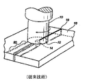
摩擦攪拌溶接(FSW)は、融解溶接方法より優れた多くの利点を有する固体溶接プロセスである。図1は、ショルダ12およびショルダから外向きに延びるピン14を有する全体的に円筒状の工具10によって特徴付けられる摩擦攪拌溶接用に使用される工具の斜視図である。ピン14は、十分な熱が発生するまで加工物16に押し付けられて回転させられ、その点で工具のピンは、可塑化された加工物材料内に突入させられる。加工物16はしばしば、接合線18のところで一緒に付き合わされる材料の2枚のシートまたはプレートである。ピン14は、接合線18のところで加工物16内に突入させられる。この工具は従来技術で開示されてきているが、この工具は新規な目的のために使用できることが明らかにされるであろう。用語「加工物(work piece)」および「ベース材料(base material)」は、この文献の最初から終わりまで同義的に使用されるであろうことにも留意する。
Friction stir welding (FSW) is a solid welding process that has many advantages over fusion welding methods. FIG. 1 is a perspective view of a tool used for friction stir welding characterized by a generally
加工物材料16に押し付けられたピン14の回転動作により生じる摩擦熱は、加工物材料を溶融温度に達することなく軟らかくさせる。工具10は接合線18に沿って横方向に移動させられ、それによって、可塑化された材料がピンの周りで前縁から後縁に流れるとき溶接部を作り出す。この結果は、他の溶接部と比較して、加工物材料16それ自体と全体的に見分けがつかない可能性のある、接合線18のところの固相結合部20になる。
Frictional heat generated by the rotational movement of the
ショルダ12が加工物の表面と接触するとき、その回転が、挿入されるピン14の周りに材料のより大きな円筒状の柱を可塑化させる追加の摩擦熱を作り出すことが観察される。このショルダ12は、工具ピン14によって生じる上向きの金属流を阻止する前進力をもたらす。
When the
FSW中、溶接される予定の領域および工具は、工具が溶接接合部の所望の長さ横断するように、互いに対して移動させられる。回転するFSW工具は連続的な熱間加工作用をもたらし、ベース金属に沿って横断方向に移動するときに狭いゾーン内で金属を可塑化させ、同時に金属をピンの前面からその後縁に移送する。工具が通過するときに液体が全く作り出されないので、溶接部ゾーンが冷却するとき、凝固は通常存在しない。結果として得られる溶接部が、欠陥なしで、再結晶した、溶接部の領域に形成される細粒ミクロ構造であることは、常にではないが、よくあることである。 During FSW, the area to be welded and the tool are moved relative to each other so that the tool traverses the desired length of the weld joint. The rotating FSW tool provides a continuous hot working action, plasticizing the metal within a narrow zone as it moves transversely along the base metal, while simultaneously transferring the metal from the front surface of the pin to its trailing edge. There is usually no solidification when the weld zone cools because no liquid is created as the tool passes. It is common, if not always, that the resulting weld is a fine-grained microstructure formed in the region of the weld that has been recrystallized without defects.
移動速度は、通常10から500mm/分であり、回転速度は200から2000rpmである。到達する温度は通常固相線温度に近いが、それより低い。摩擦攪拌溶接パラメータは、材料の熱特性、高温流れ応力および貫通深さの関数である。 The moving speed is usually 10 to 500 mm / min, and the rotational speed is 200 to 2000 rpm. The temperature reached is usually close to, but lower than, the solidus temperature. Friction stir welding parameters are a function of material thermal properties, high temperature flow stress and penetration depth.
米国特許第6,648,206号および第6,779,704号などの発明者らの何人かによる以前の特許は、以前に機能的に溶接できないと思われていた材料について摩擦攪拌溶接を実施することができる利点を教示してきた。これらの材料のいくつかは、融解溶接不可能、または溶接するのが全く困難である。これらの材料には、例えば、金属マトリックス複合材料、鋼およびステンレス鋼などの鉄合金、および非鉄材料が含まれる。やはり摩擦攪拌溶接の利点を取ることができた材料の別の部類は超合金である。超合金は、より高い溶融温度の青銅またはアルミニウムを有する材料とすることができ、混合された他の元素も同様に有することができる。超合金のいくつかの例は、一般に約534℃(1000°F)より上の温度で使用されるニッケル、鉄−ニッケル、およびコバルトベースの合金である。超合金に一般に存在する追加の元素には、限定されるものではないが、クロム、モリブデン、タングステン、アルミニウム、チタン、ニオブ、タンタル、およびレニウムが含まれる。 Previous patents by some of the inventors, such as US Pat. Nos. 6,648,206 and 6,779,704, performed friction stir welding on materials that were previously thought not to be functionally weldable The advantages that can be made have been taught. Some of these materials are not melt weldable or are quite difficult to weld. These materials include, for example, metal matrix composites, ferrous alloys such as steel and stainless steel, and non-ferrous materials. Another class of materials that could also take advantage of friction stir welding are superalloys. The superalloy can be a material having a higher melting temperature bronze or aluminum, and can also have other mixed elements as well. Some examples of superalloys are nickel, iron-nickel, and cobalt based alloys that are typically used at temperatures above about 534 ° C (1000 ° F). Additional elements commonly present in superalloys include, but are not limited to, chromium, molybdenum, tungsten, aluminum, titanium, niobium, tantalum, and rhenium.
語句「摩擦攪拌処理」は、固体状態処理と同義的に呼ばれることができることにも留意する。固体状態処理は、本明細書では通常液相を含まない可塑化状態への一時的な変態として定義される。しかしながら、いくつかの実施形態では1つまたは複数の元素が液相を通過でき、かつ依然として本発明の利益を得ることができることに留意する。 It is also noted that the phrase “friction agitation process” can be synonymously referred to as a solid state process. Solid state processing is defined herein as a temporary transformation to a plasticized state that usually does not include a liquid phase. However, it should be noted that in some embodiments, one or more elements can pass through the liquid phase and still benefit from the present invention.
摩擦攪拌処理では、工具ピンが回転させられ、処理する予定の材料内に突入されられる。この工具は材料の処理領域を横切って横断方向に移動させられる。それは、当初の材料と異なる特性を有するように改変される材料に結果としてなる可能性のある、固体処理で材料に可塑化を行わせる作用である。 In the friction stir processing, the tool pin is rotated and rushed into the material to be processed. The tool is moved transversely across the material processing area. It is the action of causing the material to plasticize in a solid process that can result in the material being modified to have different properties than the original material.
FSWに伴う主な欠点は、溶接の終わりに加工物内に残される残留孔である。多くの場合、エンドタブ(run off tab)を溶接部の端部のところに使用し、後で取り除くことができるので、これは問題点にならない。溶接が進行するとき端部孔をなくすために後退可能なピンを使用することができるが、この工具および設備は大規模でありコストが高い。FSW中、工具を溶接部から徐々に引き抜くことを可能にする工具形状も使用することができるが、既存の溶接に対して追加される熱サイクルと組み合わされた追加の処理時間はコストを増加させ、かつベース金属特性を低下させる。 The main drawback with FSW is residual holes left in the work piece at the end of the weld. In many cases, this is not a problem because a run off tab can be used at the end of the weld and later removed. Although retractable pins can be used to eliminate the end holes as welding proceeds, the tools and equipment are large and costly. Tool shapes that allow the tool to be gradually pulled out of the weld during FSW can also be used, but the additional processing time combined with thermal cycles added to existing welds increases costs. And lower the base metal properties.
摩擦攪拌スポット溶接(FSSW)が現在、高度な高強度鋼を重ね溶接形態で接合するために実験的に使用されている。FSSWは、米国特許出願第20050178817号に記載されるように、アルミニウム構成部品を重ね溶接するために商業的に使用されている。2つの手法が現行使用される。 Friction stir spot welding (FSSW) is currently used experimentally to join advanced high strength steels in lap weld form. FSSW is commercially used to lap weld aluminum components as described in US Patent Application No. 20050178817. Two approaches are currently used.
第1の手法は、加工物が一緒にスポット摩擦攪拌溶接されるまで、ピン工具(ピンおよびショルダから構成されるFSSW工具)を加工物内に突入させることを含む。この方法に伴う欠点は、図2に示すようにピンの後に残される穴26である。加工物28の間の結合は工具のショルダの下で達成されるが、このピン穴は溶接部の強度を低下させる。
The first approach involves rushing a pin tool (FSSW tool comprised of pins and shoulders) into the workpiece until the workpieces are spot friction stir welded together. The drawback with this method is the
第2の方法は、材料をピン穴内に強制的に戻す設備の設計を含む(米国特許第6,722,556号)。この方法は、大きなスピンドルヘッド、固定要件、およびスポット溶接を行うために必要な荷重のために極めて面倒である。 The second method involves the design of equipment that forces the material back into the pin holes (US Pat. No. 6,722,556). This method is extremely cumbersome due to the large spindle head, the fixing requirements, and the load required to perform spot welding.
迅速かつ経済的な方法でリベットを使用してFSSWを実施するために、部分的に消耗可能な工具を使用するシステムおよび方法を提供できることは、金属加工物接合の最新技術分野より優れた利点となるであろう。 The ability to provide systems and methods that use partially consumable tools to perform FSSW using rivets in a quick and economical manner has advantages over the state of the art of metal workpiece joining. It will be.
本発明の第1の態様では、少なくとも部分的に消耗可能なピンを使用して摩擦攪拌リベット締結を実施するための摩擦攪拌工具が提供される。このピンは、その底部表面に切込み縁部を含む。この工具は、ピンによって第2の材料と重なり合う第1の材料内に切り込むことを可能にするように第1の速度で回転させられ、ピンが十分な深さまで切り込んだ後、この工具の回転速度は増加させられ、それによって消耗可能なピン、第1の材料、および第2の材料の可塑化を可能にし、次いでこの工具は停止するまで急速に減速され、ピン、第1の材料、および第2の材料の間の拡散結合が可能になる。 In a first aspect of the invention, a friction stir tool is provided for performing friction stir rivet fastening using at least partially consumable pins. The pin includes a cut edge on its bottom surface. The tool is rotated at a first speed to allow the pin to cut into the first material that overlaps the second material, and after the pin has been cut to a sufficient depth, the rotational speed of the tool Is increased, thereby allowing plasticization of the consumable pin, the first material, and the second material, and then the tool is rapidly decelerated until it stops, the pin, the first material, and the first material Diffusion bonding between the two materials is possible.
本発明のこれらのおよび他の目的、特徴、利点および代替の態様は、添付の図面と組み合わせて行われる以下の詳細な説明の考察から当業者に明らかになるであろう。 These and other objects, features, advantages and alternative aspects of the present invention will become apparent to those skilled in the art from consideration of the following detailed description taken in conjunction with the accompanying drawings.
次に、本発明の様々な要素に数字の指定が与えられ、当業者が本発明を作りかつ使用できるようにするように本発明が論じられるであろう図面に対して参照が行われる。以下の説明は本発明の原理の例示でしかなく、添付の特許請求の範囲を狭めるものとして見るべきではないことを理解されたい。 Reference will now be made to the drawings in which the invention will be discussed so as to give numerical designations to the various elements of the invention and to enable those skilled in the art to make and use the invention. It should be understood that the following description is only illustrative of the principles of the invention and should not be viewed as narrowing the scope of the appended claims.
本発明の第1の態様では、上記で述べた接合の問題点の多くを解決するために新規な手法が使用される。分離可能かつ少なくとも部分的に消耗可能なピンと組み合わされた非消耗可能なショルダを有する回転摩擦攪拌リベット締結工具が、本発明の摩擦攪拌リベット締結接合法の基礎を形成する。このピンは、全部消耗可能であっても部分的に消耗可能であってもよい。図3は、どのようにこの工具を構成することができるかの例を示す。 In the first aspect of the present invention, a novel approach is used to solve many of the bonding problems described above. A rotary friction stir rivet fastening tool having a non-consumable shoulder combined with a separable and at least partially consumable pin forms the basis of the friction stir rivet fastening joining method of the present invention. This pin may be fully consumable or partially consumable. FIG. 3 shows an example of how this tool can be constructed.
図3は、ショルダ領域32および分離可能かつ少なくとも部分的に消耗可能なピン34を有する摩擦攪拌リベット締結工具30を示す。この具体的な実施形態では、この分離可能かつ少なくとも部分的に消耗可能なピン34は、小さな隙間36を含む。この小さな隙間36は、ピン34のずっとより小さなピン直径部分42によって形成される。ピン34のこの小さなピン直径部分42は、破断するようにされるであろう。この小さな隙間36は、ピン34の分離可能な部分38が、リベットとして加工物内に埋め込まれて残ることを可能にする。ピン34の非分離部分40は、説明されるであろうように、別のピンセグメントの頂部でもあることができることにも留意する。
FIG. 3 shows a friction stir
説明として図4を使用すると、本発明のこの第1の実施形態の工具を使用して鋼または別の金属を摩擦リベット締結するために、この工具30は、工具のピン34が第1の加工物材料50をその中に穴54を形成するように取り除いて機械加工することができる、ある速度で回転させられる。所望の穴を機械加工するのを容易にするために、ピン34の端部に機構を加えることができる。例えば、切込み機構44がこの第1の実施形態に示されている。
Using FIG. 4 as an illustration, to use the tool of this first embodiment of the present invention to friction rivet steel or another metal, the
この穴54の深さ56が第1の加工物材料50を完全に貫通し、少なくとも部分的に第2の加工物材料52内に延びることは好ましいが必須ではない。
It is preferred, but not essential, that the
用途に応じて、この穴54は第1の加工物材料50内に部分的にのみ延び、または、第1の加工物材料を完全に貫通するが第2の加工物材料52内には延びず、または、第1の加工物材料を完全に貫通するが第2の加工物材料内に部分的にのみ延び、または、第1と第2の加工物材料の両方を実質的に貫通して延びるようにすることができることを理解されたい。最初の穴54が作られた後、次いで工具30は、ピン34に摩擦攪拌リベット締結の暗黙の原理に従った所望のレベルの貫通を行わせることができる。ピン34は、第1と第2の加工物材料50、52の両方を完全に貫通して延びることができ、あるいは、第1の加工物材料を完全に貫通するが第2の加工物材料内に部分的にのみ延びることができる。この場合も、これは使用者の用途によって変わる。
Depending on the application, this
この第1の実施形態では、穴54の深さ56が図4に示すように第2の加工物52内に延びた後、工具30の回転速度は、ピン30と、一緒に接合されつつある2つの第1と第2の加工物50、52との間に熱を発生させるように減速させられる。工具30を保持しかつ回転させているスピンドル(図示せず)は、直ちに停止させるか、それとも工具を回転させるために必要なトルクがより小さなピン直径部分42の剪断強度を超えるまで減速させることができる。より小さなピン直径部分42は、特定のトルクでピン34の分離可能な部分38を工具30から剪断して離すように設計される。
In this first embodiment, after the
この第1の実施形態では、ピン34の分離可能な部分38が工具30から剪断して離された後、この工具は後退させられ、新たなピン34と交換することができる。第1と第2の加工物材料50、52内に後に残されたピン34またはリベットの分離可能な部分38は、加工物内に摩擦溶接される。第1と第2の加工物50、52の間の工具ショルダの下のみならず、ピン34またはリベットの周りにも結合部が存在する。
In this first embodiment, after the
図5に示すような本発明の代替実施形態では、工具60は、中央軸を貫通して配設される穴62を有する。この穴62は、(ここではより小さな直径のピン部分72によって分離される3つのセグメントを有して示される)多重分割されたピン64が挿入され、必要に応じて穴62を通り押されることができるようにする。この多重分割されたピン64は、より小さな直径のピン部分72を有する複数の隙間66を含む。次いである種のプランジャー機構68が、この多重分割されたピン64を工具60を貫通して押し、加工端部70から外へ出すために使用される。多重分割されたピン64の各セグメントが破断して離されるとき、プランジャー機構68は、十分なピン64が次の摩擦攪拌リベット締結プロセスのために露出されるまで、多重分割されたピンを穴62を貫通して押し下げる。このような方法で、停止させかつ多重分割されたピン64を再装填しなければならないことなく、多数のリベットを加工物内に挿入することができる。
In an alternative embodiment of the present invention as shown in FIG. 5, the
多重分割されたピン64に使用できるセグメントの数は、3つに限られると見なすべきではない。図5は説明目的のためのみである。より多くのセグメントを多重分割されたピン64に配設することができる。分割数は、工具60の長さおよびプランジャー機構68の長さによっても変わる。
The number of segments that can be used for
図6は、自動的かつ迅速な摩擦攪拌リベット締結プロセスに使用できる多重分割されたピン64を図示するために提供される。多重分割されたピン64のセグメントは、摩擦攪拌リベット締結工具60の中央軸を貫通する穴内に配設できるように、同軸である。
FIG. 6 is provided to illustrate a multiple segmented
本発明に使用できるショルダを有する工具を作り出すために使用される材料は、本発明者のうちの何人かによって作り出され、摩擦攪拌溶接の固体接合プロセス中に鋼およびステンレス鋼などの高溶融温度材料を一緒に接合するのに使用できる工具に見出すことができる。 The materials used to create a tool with a shoulder that can be used in the present invention are produced by some of the inventors, and high melting temperature materials such as steel and stainless steel during the friction stir welding solid joining process Can be found in tools that can be used to join together.
この技術は、特別な摩擦攪拌溶接工具を使用することを含む。このショルダは、多結晶立方晶窒化ホウ素(PCBN)および多結晶ダイヤモンド(PCD)などの材料を使用して作り出すことができる。含むことができる他の材料には、タングステン、レニウム、イリジウム、チタン、モリブデン等の難溶性物質が存在する。 This technique involves the use of special friction stir welding tools. This shoulder can be created using materials such as polycrystalline cubic boron nitride (PCBN) and polycrystalline diamond (PCD). Other materials that can be included include poorly soluble materials such as tungsten, rhenium, iridium, titanium, molybdenum and the like.
本発明の原理を使用して接合できる加工物には、青銅およびアルミニウムより高い溶融温度を有する材料が含まれる。この部類の材料には、金属マトリックス複合材料、鋼およびステンレス鋼などの鉄合金、非鉄材料、超合金、チタン、通常表面硬化に使用されるコバルト合金、および空気焼入れ鋼または高速度鋼が含まれるが、これらに限定されない。しかしながら本発明は、上記で説明したより高い溶融温度の定義内に含まれない、全ての他のより低い溶融温度材料と考えることができる材料に対しても使用することができる。 Workpieces that can be joined using the principles of the present invention include materials having higher melting temperatures than bronze and aluminum. This class of materials includes metal matrix composites, ferrous alloys such as steel and stainless steel, non-ferrous materials, superalloys, titanium, cobalt alloys commonly used for surface hardening, and air-hardened or high-speed steels However, it is not limited to these. However, the present invention can also be used for materials that can be considered all other lower melting temperature materials that are not included within the definition of higher melting temperatures described above.
工具30のショルダ32は、ショルダの第1の加工物50への接着を防止し、かつ優れた熱安定性および耐磨耗特性をもたらすことができる多結晶立方晶窒化ホウ素または同様に説明される材料から作ることができる。いくつかのショルダ形態をリベットヘッドの形状を形成するために、あるいはピン34が加工物50、52内に摩擦溶接された後で、リベットヘッドを切り離すためにさえ使用することができる。
The
ピン34用に使用される材料は一般に、摩擦攪拌リベット締結プロセス中に消耗することができる材料になりそうなものである。そのような材料は、第1と第2の加工物材料の間の結合を好ましく高めるであろうし、摩擦攪拌溶接の分野の当業者に知られている。
The material used for the
本発明の代替実施形態には、やはり重要な要素であると見なされるべき様々な態様が含まれる。第1に、リベットとして挿入されることになるピン34の端部に様々な切込構造または外形を使用できる。図3に示す機構の代わりに、代替の切込構造として螺旋状の刻み目の外形を使用することができる。
Alternative embodiments of the invention include various aspects that should still be considered critical elements. First, various notch structures or profiles can be used at the end of the
別の代替実施形態では、アルゴンまたは二酸化炭素などの不活性ガスを、摩擦攪拌リベット締結中の酸化を防止するために工具30の中心を通り流れるようにすることができる。
In another alternative embodiment, an inert gas such as argon or carbon dioxide can be flowed through the center of the
別の代替実施形態では、3つ以上の加工物を本発明の摩擦攪拌リベット締結プロセスを使用して接合することができる。したがって、ピン34のセグメントの長さは、それに準じて調整されるであろう。
In another alternative embodiment, three or more workpieces can be joined using the friction stir rivet fastening process of the present invention. Accordingly, the length of the segment of
別の代替実施形態では、接合されつつある加工物は、用途に応じて同じ材料または異なる材料であり得ることに留意されたい。 It should be noted that in another alternative embodiment, the workpieces being joined can be the same material or different materials depending on the application.
同様に、ピンに使用される材料は、加工物と異なる材料、または、加工物のうちの少なくとも1つと同じ材料、または、全ての加工物の材料と同じ材料とすることができる。 Similarly, the material used for the pins can be a different material from the workpiece, the same material as at least one of the workpieces, or the same material as the material of all workpieces.
ピン外形は大きく変更することができる。このピンの外形は、切込プロセスおよび摩擦攪拌リベット締結プロセスを実施するであろう、テーパの付いた形状、6角形状、または任意の所望の形状とすることができる。この形状は、所望の結合特性または使用される様々な材料の強度などの、様々な態様により変わるであろう。
The pin outline can be changed greatly. The pin profile can be tapered, hexagonal, or any desired shape that will perform the incision process and friction stir rivet fastening process. This shape will vary depending on various aspects, such as the desired bonding characteristics or the strength of the various materials used.
別の実施形態では、このピンは中空でもあり得る。このピンは、棒またはワイヤの形態であり、工具の中心を貫通して自動的に供給することができる。ピンのために正方形の形状が使用されるとき、これによって工具からのトルクをピンまたはリベットに伝達できるようになる。しかしながら、トルク伝達する他の外形も使用できる。ピン材料の外径上のクランプ力またはクランプ機構が、回転力が加えられるときにピンが工具内で滑るのを防ぐのに十分である限り、ピンのために丸い形状でさえ使用することができる。 In another embodiment, the pin can be hollow. This pin is in the form of a bar or wire and can be automatically fed through the center of the tool. When a square shape is used for the pin, this allows torque from the tool to be transmitted to the pin or rivet. However, other profiles that transmit torque can be used. As long as the clamping force or clamping mechanism on the outer diameter of the pin material is sufficient to prevent the pin from sliding in the tool when a rotational force is applied, even a round shape can be used for the pin .
このピンまたはリベットは、加工物貫通を容易にするために、様々な硬度または硬度分布を有することができる。 The pins or rivets can have various hardnesses or hardness distributions to facilitate workpiece penetration.
この工具は、特定の位置または荷重値に対して1から10,000RPMの範囲のRPMで作動させることができる。 The tool can be operated at RPMs ranging from 1 to 10,000 RPM for a specific position or load value.
この工具は、融解スポット溶接と同じ構造で作動させることができる。例えば、C字形クランプ構造において溶接チップと一緒にクランプを利用するのではなく、直径が小さい回転工具(図3)をロボットの端部のC字形クランプ内に配置することができる。このC字形クランプ構造も手動で使用することができる。 This tool can be operated with the same structure as melt spot welding. For example, rather than utilizing a clamp with a welding tip in a C-shaped clamp structure, a small diameter rotating tool (FIG. 3) can be placed in the C-shaped clamp at the end of the robot. This C-shaped clamp structure can also be used manually.
このピンは、機械的取付具をその位置で使用できるように、「ヘッド」に留め具を有することができる。例えば、摩擦リベットの端部は、加工物が接合された後で加工物の上方に突出するように残されるねじ切りされたスタブを有することができる。次いでナットを、加工物に別の構成部品を取り付けるために使用できる。 This pin can have a fastener on the “head” so that the mechanical fixture can be used in that position. For example, the end of the friction rivet can have a threaded stub that is left to protrude above the workpiece after the workpieces are joined. The nut can then be used to attach another component to the workpiece.
この摩擦攪拌リベット締結プロセスの利点のうちのいくつかは、それらに限定されると見なすべきでないが、迅速で、エネルギ入力プロセス要件が低く、固体状態プロセスなので残留応力が低く、従来型のリベット締結のように事前にあけられた穴が全く必要なく、加工物の歪が低減されまたはなくされ、FSSWでのように加工物内に穴が全く残されておらず、プロセスを密閉された領域で使用でき、z軸の力が抵抗スポット溶接に必要な現行の力と同程度であり、ショルダ/ピン比率を接合部強度を最適化するために特定の熱分布を発生させるようなサイズにすることができ、耐食性ピン材料を使用でき、このプロセスがある高められた温度で完了するのでピンまたはリベットの形成が降伏せずより大きなエネルギ吸収特性を有し、このピンまたはリベット材料がより強い強度のために加工物材料に勝ることができ、かつ、加工物内のさらなる割れ伝播を防止するためにリベットまたはピンが割れの先端のところに使用できる、固体状態接合プロセスが含まれる。 Some of the advantages of this friction stir rivet fastening process should not be considered limited, but they are fast, have low energy input process requirements, are solid state processes and have low residual stress, and traditional rivet fastening No pre-drilled holes are required, work piece distortion is reduced or eliminated, no holes are left in the work piece as in FSSW, and the process is closed in a sealed area Can be used, the z-axis force is similar to the current force required for resistance spot welding, and the shoulder / pin ratio is sized to generate a specific heat distribution to optimize joint strength Corrosion-resistant pin material can be used and the process is completed at an elevated temperature so that the formation of pins or rivets does not yield and has greater energy absorption properties Solid state bonding where the rivet or rivet material can outperform the workpiece material due to stronger strength and the rivet or pin can be used at the crack tip to prevent further crack propagation in the workpiece Process is included.
このピンは、接合される材料より硬い材料を使用して作られるのが一般的である。しかしながら、このピンは、より軟らかいが十分な力でおよび十分に迅速に押されることができ、それはより硬い加工物材料を接合するために使用することができる。 This pin is typically made using a material that is harder than the material to be joined. However, this pin is softer but can be pushed with sufficient force and quickly enough that it can be used to join harder workpiece materials.
本発明の別の態様は、ピンによって加工物の穴から切断され、形成される材料を取り除くというオプションがある。材料を取り除く1つの方法は、ペッキング・モーション(pecking motion)を使用することである。工具のペッキング・モーションは、この材料を取り除くために流体流と組み合わせることもできる。この流体は、圧縮性または非圧縮性であり、ガス、空気、ミスト、および水を含むことができる。 Another aspect of the present invention is the option of removing the material formed by being cut from the hole in the workpiece by the pins. One way to remove material is to use a pecking motion. Tool pecking motion can also be combined with fluid flow to remove this material. The fluid is compressible or incompressible and can include gas, air, mist, and water.
前に述べたように、本発明は異なる材料を一緒に接合するために使用することができ、3つの物体(2つの加工物と1つのピン)という構成に限定されない。材料の多数の層を同時に接合することができる。結合される材料の溶融温度より低い温度勾配に材料が曝される限り、任意の数の材料を結合することができる。 As previously mentioned, the present invention can be used to join different materials together and is not limited to the configuration of three objects (two workpieces and one pin). Multiple layers of material can be bonded simultaneously. Any number of materials can be bonded as long as the material is exposed to a temperature gradient below the melting temperature of the materials to be bonded.
工具の表面移動速度の範囲は、毎分0.1mmから毎分10メートルであると見なされるべきである。工具の回転速度は、1rpmから100,000rpmまで変更することができる。 The range of tool surface movement speeds should be considered to be from 0.1 mm / min to 10 meters / min. The rotational speed of the tool can be changed from 1 rpm to 100,000 rpm.
被覆を工具に、または、接合される加工物に、または、工具および加工物の両方に、使用することができる。 The coating can be used on the tool, on the workpiece to be joined, or on both the tool and the workpiece.
本発明の工具は、CBNショルダ、または結合される材料より高いまたは低い弾性率を有する異なる材料を有する工具などの、複合工具とすることができる。 The tool of the present invention can be a composite tool, such as a CBN shoulder, or a tool having a different material with a higher or lower modulus than the material to be bonded.
結合される材料の硬度は、ロックウエル・スケールA、BおよびC上の全ての材料を含むと見なすべきである。 The hardness of the material to be bonded should be considered to include all materials on the Rockwell scales A, B and C.
本発明のピンの切込縁部は、任意の適切な切込み形状を有することができる。したがって、結合部を生じさせる目的で切り込み、切り込みと加熱、および加熱を可能にする任意の機構をピン上に含むことができる。このピンはねじを設けることもできる。したがって、このピンは切込形状を有さなければならないことはない。一つの代替実施形態は、他の加工物材料内に、またはそれを貫通して穴または開口部を作り出すことを可能にするために、ピンの加熱を使用する。
The cutting edge of the pin of the present invention can have any suitable cutting shape. Thus, cutting , cutting and heating, and any mechanism that allows heating can be included on the pin for the purpose of creating a joint. This pin can also be threaded. Therefore, this pin does not have to have a notch shape. One alternative embodiment uses pin heating to allow holes or openings to be created in or through other workpiece materials.
本発明は、作り出される穴の軸方向にかつ側面を含む、複数の平面上の拡散結合を可能にする。 The present invention allows diffusion bonding on multiple planes, including in the axial direction and including the sides of the hole being created.
上記で説明した構成は、本発明の原理の応用の例示でしかないことを理解されたい。多数の改変および代替構成は、本発明の趣旨および範囲から逸脱することなく当業者によって考え出されることができる。添付の特許請求の範囲は、そのような改変および構成を包含することを意図している。 It should be understood that the configurations described above are merely illustrative of the application of the principles of the present invention. Numerous modifications and alternative configurations can be devised by those skilled in the art without departing from the spirit and scope of the invention. The appended claims are intended to cover such modifications and arrangements.
Claims (16)
(2)少なくとも部分的に消耗可能なピンを有する摩擦攪拌リベット締結工具を準備するステップであって、前記少なくとも部分的に消耗可能なピンがその作業端部に、前記少なくとも2つの加工物の少なくとも第1の加工物内に切り込むのに適した切込機構を含むステップと、
(3)前記少なくとも部分的に消耗可能なピンの前記切込機構が前記少なくとも第1の加工物内に所望の深さまで切り込むことを可能にするように前記工具を第1の速度で回転させて、前記少なくとも部分的に消耗可能なピンと少なくとも同じ幅の穴を形成するステップと、
(4)前記摩擦攪拌リベット締結工具を前記第1の速度より速い異なる速度で回転させ、それによって前記少なくとも部分的に消耗可能なピンおよび前記少なくとも2つの加工物の可塑化を可能にするステップと、
(5)前記摩擦攪拌リベット締結工具を前記第1の速度より遅い異なる速度で回転させ、前記少なくとも部分的に消耗可能なピンと前記少なくとも2つの加工物の拡散結合を可能にするステップと
を含む、摩擦攪拌リベット締結工具内に配設される少なくとも部分的に消耗可能なピンを使用して少なくとも2つの加工物を一緒に拡散結合する方法。(1) superposing at least two workpieces;
(2) providing a friction stir rivet fastening tool having at least a partly consumable pin, wherein the at least partly consumable pin is at the working end of at least two of the at least two workpieces; Including a cutting mechanism suitable for cutting into the first workpiece;
(3) the said tool to at least partially consumable pin of the cutting mechanism allows the cutting to the desired depth in said at least first workpiece within is rotated at a first speed a step wherein you forming a hole at least partially consumable pin and at least as wide,
(4) rotating the friction stir rivet setting tool at a different speed faster than the first speed , thereby allowing the at least partially consumable pin and the at least two workpieces to be plasticized; ,
(5) rotating the friction stir rivet setting tool at a different speed slower than the first speed to allow diffusion bonding of the at least partially consumable pin and the at least two workpieces; A method of diffusion bonding at least two workpieces together using at least partially consumable pins disposed in a friction stir rivet setting tool.
(2)前記穴内に前記少なくとも部分的に消耗可能なピンを配設するステップと
をさらに含む、請求項1に記載の方法。(1) forming a hole along a central axis of the friction stir rivet fastening tool;
And (2) disposing the at least partially consumable pin in the hole.
(2)複数の加工物を貫通する穴を形成するように、前記消耗可能なピンを前記複数の加工物に押し付けて第1の速度で回転させるステップと、
(3)前記消耗可能なピンを前記第1の速度より速い異なる速度で回転させ、それによって前記消耗可能なピンおよび前記複数の加工物の可塑化を可能にするステップと、
(4)前記消耗可能なピンと前記複数の加工物の拡散結合を可能にするように、前記消耗可能なピンの回転を停止させるステップと
を含む、消耗可能なピンを使用して複数の加工物を一緒に摩擦攪拌リベット締結する方法。(1) preparing a friction stir rivet fastening tool having a consumable pin including a cutting mechanism at its processing end;
(2) pressing the consumable pin against the plurality of workpieces to rotate at a first speed so as to form a hole penetrating the plurality of workpieces;
(3) rotating the consumable pin at different speeds faster than the first speed , thereby allowing plasticization of the consumable pin and the plurality of workpieces;
(4) Stopping rotation of the consumable pin to allow diffusion bonding of the consumable pin and the plurality of workpieces, and using the consumable pin to provide a plurality of workpieces. How to fasten friction stir rivets together.
前記非消耗可能なショルダの中央軸に沿った穴内に配設される消耗可能なピンであって、前記消耗可能なピンの一部分の破断を可能にするより小さな直径のピンの部分を含む消耗可能なピンとを備え、
前記消耗可能なピンが、前記軸部が回転させられるときの前記非消耗可能なショルダ内の前記穴内での回転が防止され、かつ
前記消耗可能なピンが、その加工端部に切込機構を含む、摩擦攪拌リベット締結工具。A shank having a non-consumable shoulder;
A consumable pin disposed in a hole along a central axis of the non-consumable shoulder, comprising a portion of a smaller diameter pin that allows a portion of the consumable pin to break. With a pin,
The consumable pin is prevented from rotating in the hole in the non-consumable shoulder when the shaft is rotated, and the consumable pin has a cutting mechanism at its processing end. Including friction stir rivet fastening tool.
前記非消耗可能なショルダに対向する前記軸部の端部に配設されるプランジャー機構とを備え、前記プランジャー機構が前記摩擦攪拌リベット締結工具の加工端部に向かって前記消耗可能なピンを前進させる、請求項11に記載の摩擦攪拌リベット締結工具。A hole disposed completely through the shank to the non-consumable shoulder;
A plunger mechanism disposed at an end portion of the shaft portion facing the non-consumable shoulder, and the plunger mechanism is a pin that is consumable toward a processing end portion of the friction stir rivet fastening tool. The friction stir rivet fastening tool according to claim 11 , wherein the tool is advanced.
Applications Claiming Priority (5)
| Application Number | Priority Date | Filing Date | Title |
|---|---|---|---|
| US80462806P | 2006-06-13 | 2006-06-13 | |
| US60/804,628 | 2006-06-13 | ||
| US81639606P | 2006-06-23 | 2006-06-23 | |
| US60/816,396 | 2006-06-23 | ||
| PCT/US2007/014004 WO2007146402A2 (en) | 2006-06-13 | 2007-06-13 | Three-body joining using friction stir processing techniques |
Publications (3)
| Publication Number | Publication Date |
|---|---|
| JP2009539621A JP2009539621A (en) | 2009-11-19 |
| JP2009539621A5 JP2009539621A5 (en) | 2012-07-12 |
| JP5167254B2 true JP5167254B2 (en) | 2013-03-21 |
Family
ID=38832551
Family Applications (1)
| Application Number | Title | Priority Date | Filing Date |
|---|---|---|---|
| JP2009515503A Active JP5167254B2 (en) | 2006-06-13 | 2007-06-13 | Joining three objects using friction stir processing technology |
Country Status (8)
| Country | Link |
|---|---|
| US (1) | US7845545B2 (en) |
| EP (1) | EP2026929B1 (en) |
| JP (1) | JP5167254B2 (en) |
| CN (1) | CN101466492B (en) |
| AT (1) | ATE538895T1 (en) |
| CA (1) | CA2653281C (en) |
| DK (1) | DK2026929T3 (en) |
| WO (1) | WO2007146402A2 (en) |
Families Citing this family (35)
| Publication number | Priority date | Publication date | Assignee | Title |
|---|---|---|---|---|
| US8632850B2 (en) * | 2005-09-26 | 2014-01-21 | Schultz-Creehan Holdings, Inc. | Friction fabrication tools |
| US20080041921A1 (en) | 2005-09-26 | 2008-02-21 | Kevin Creehan | Friction stir fabrication |
| US9266191B2 (en) | 2013-12-18 | 2016-02-23 | Aeroprobe Corporation | Fabrication of monolithic stiffening ribs on metallic sheets |
| US8875976B2 (en) * | 2005-09-26 | 2014-11-04 | Aeroprobe Corporation | System for continuous feeding of filler material for friction stir welding, processing and fabrication |
| US9511446B2 (en) | 2014-12-17 | 2016-12-06 | Aeroprobe Corporation | In-situ interlocking of metals using additive friction stir processing |
| US9511445B2 (en) | 2014-12-17 | 2016-12-06 | Aeroprobe Corporation | Solid state joining using additive friction stir processing |
| CN101394964B (en) * | 2006-03-09 | 2012-05-30 | 古屋金属株式会社 | Tool for friction stir welding, method of welding with the same, and processed object obtained by the same |
| WO2007116629A1 (en) * | 2006-04-11 | 2007-10-18 | Kawasaki Jukogyo Kabushiki Kaisha | Method and device for inspecting object formed by friction stir joining |
| US7726541B2 (en) * | 2008-01-15 | 2010-06-01 | Embraer-Empresa Brasileira De Aeronautica S.A. | Friction plug welding methods and systems |
| WO2010006106A1 (en) * | 2008-07-09 | 2010-01-14 | Fluor Technologies Corporation | High-speed friction stir welding |
| WO2010041945A2 (en) * | 2008-10-10 | 2010-04-15 | Stichting Materials Innovation Institute (M2I) | Friction stir welding with heated supply material |
| NL2002083C (en) * | 2008-10-10 | 2010-04-13 | Stichting Materials Innovation Inst M2I | FRICTION STIR WELDING WITH HEATED DELIVERY MATERIAL. |
| US20110274943A1 (en) * | 2008-12-24 | 2011-11-10 | Osaka University | Metal material processing method, structure processed using metal material processing method and rotary tool |
| US8464926B2 (en) * | 2009-10-30 | 2013-06-18 | Wisconsin Alumni Research Foundation | Method of friction stir welding dissimilar metals and workpiece assemblies formed thereby |
| US8066174B2 (en) * | 2010-04-30 | 2011-11-29 | Siemens Energy, Inc. | Filler rotated friction stir welding |
| CN101817142A (en) * | 2010-05-20 | 2010-09-01 | 上海交通大学 | Self-piercing frictional rivet welding connecting device |
| JP2013535338A (en) * | 2010-08-02 | 2013-09-12 | メガスター・テクノロジーズ・エルエルシー | A system for using high rotational speeds to minimize loads during friction stir welding |
| US20120080506A1 (en) * | 2010-09-23 | 2012-04-05 | Tecnara Fsw Company, Llc | Method for holding high speed friction spot joining tools |
| JP2012107593A (en) * | 2010-11-19 | 2012-06-07 | Hitachi Ltd | Steam turbine valve |
| DE102011106505A1 (en) | 2011-06-15 | 2012-12-20 | Eurocopter Deutschland Gmbh | Welding tool for connecting at least two workpieces, welding process and workpiece |
| US9764375B2 (en) * | 2012-03-02 | 2017-09-19 | Brigham Young University | Friction bit joining of materials using a friction rivet |
| WO2013131075A1 (en) * | 2012-03-02 | 2013-09-06 | Megastir Technologies Llc | Friction bit joining of materials |
| PL3094429T3 (en) * | 2014-01-13 | 2021-08-02 | Brigham Young University | Friction bit joining of materials using a friction rivet |
| US10695861B2 (en) | 2014-07-10 | 2020-06-30 | Mazak Corporation | Friction stir extrusion of nonweldable materials for downhole tools |
| US10799980B2 (en) | 2016-10-06 | 2020-10-13 | Mazak Corporation | Compressible friction stir welding tool for conventional machining equipment |
| US11130192B2 (en) | 2017-08-30 | 2021-09-28 | Mazak Corporation | Instrumented tool handler for friction stir welding |
| EP3450082B1 (en) | 2017-08-31 | 2020-12-16 | Mazak Corporation | Devices and methods for increased wear resistance during low temperature friction stir processing |
| JP7089034B2 (en) | 2017-10-31 | 2022-06-21 | メルド マニファクチャリング コーポレーション | Solid-state laminated modeling system as well as material composition and structural background |
| US10478916B2 (en) * | 2017-11-02 | 2019-11-19 | GM Global Technology Operations LLC | Method and apparatus for joining components with friction pins |
| EP3486021B1 (en) | 2017-11-21 | 2023-05-03 | Megastir Technologies LLC | Friction stir processing tool with radial protrusion |
| US11440133B2 (en) | 2018-05-04 | 2022-09-13 | Mazak Corporation | Low-cost friction stir processing tool |
| CN110465737B (en) | 2018-05-09 | 2023-11-21 | 杨百翰大学 | System and method for friction bit engagement |
| WO2020067331A1 (en) * | 2018-09-26 | 2020-04-02 | 日本製鉄株式会社 | Joint structure, joining method, and member for automobiles |
| CN111906432B (en) * | 2020-08-04 | 2022-07-12 | 沈阳航空航天大学 | Friction stir lap joint method based on impinging stream |
| US20230078463A1 (en) * | 2021-09-13 | 2023-03-16 | Ohio State Innovation Foundation | Self-filling friction stir processing tool and methods of using the same |
Family Cites Families (18)
| Publication number | Priority date | Publication date | Assignee | Title |
|---|---|---|---|---|
| SU1466896A1 (en) * | 1984-09-06 | 1989-03-23 | Предприятие П/Я Г-4459 | Method of friction welding of hollow part with a blank plug |
| NO942790D0 (en) * | 1994-03-28 | 1994-07-27 | Norsk Hydro As | Method of friction welding and device for the same |
| US5697544A (en) * | 1996-03-21 | 1997-12-16 | Boeing North American, Inc. | Adjustable pin for friction stir welding tool |
| US5794835A (en) * | 1996-05-31 | 1998-08-18 | The Boeing Company | Friction stir welding |
| JP3081809B2 (en) * | 1997-02-21 | 2000-08-28 | 昭和アルミニウム株式会社 | Metal material joining method |
| JP3045698B2 (en) * | 1997-11-28 | 2000-05-29 | 昭和アルミニウム株式会社 | Metal material joining method |
| US6457629B1 (en) * | 1999-10-04 | 2002-10-01 | Solidica, Inc. | Object consolidation employing friction joining |
| US6497355B1 (en) * | 1999-10-13 | 2002-12-24 | The United States Of America As Represented By The Administrator Of The National Aeronautics And Space Administration | System for controlling the stirring pin of a friction stir welding apparatus |
| JP4488395B2 (en) * | 2000-08-01 | 2010-06-23 | 山下ゴム株式会社 | Method for joining two members |
| US6769595B2 (en) * | 2000-12-20 | 2004-08-03 | Alcoa Inc. | Friction plunge riveting |
| US6742697B2 (en) * | 2002-04-29 | 2004-06-01 | The Boeing Company | Joining of structural members by friction plug welding |
| US6854634B2 (en) * | 2002-05-14 | 2005-02-15 | The Boeing Company | Method of manufacturing rivets having high strength and formability |
| JP2004025296A (en) * | 2002-06-28 | 2004-01-29 | Shin Meiwa Ind Co Ltd | Friction welding device and method |
| JP4346887B2 (en) * | 2002-10-25 | 2009-10-21 | 川崎重工業株式会社 | Welding tool, friction stir welding apparatus, and friction stir welding method |
| US20050045695A1 (en) * | 2003-08-29 | 2005-03-03 | Subramanian Pazhayannur Ramanathan | Apparatus and method for friction stir welding using a consumable pin tool |
| US6988651B2 (en) * | 2004-02-17 | 2006-01-24 | General Motors Corporation | Friction stir rivet drive system and stir riveting methods |
| JP4755447B2 (en) * | 2005-06-02 | 2011-08-24 | 川崎重工業株式会社 | Friction stirrer and friction stirrer method |
| JP5059337B2 (en) * | 2006-04-11 | 2012-10-24 | 川崎重工業株式会社 | Method for modifying the structure of castings |
-
2007
- 2007-06-13 AT AT07815098T patent/ATE538895T1/en active
- 2007-06-13 CA CA2653281A patent/CA2653281C/en active Active
- 2007-06-13 CN CN2007800219534A patent/CN101466492B/en active Active
- 2007-06-13 JP JP2009515503A patent/JP5167254B2/en active Active
- 2007-06-13 EP EP07815098A patent/EP2026929B1/en active Active
- 2007-06-13 WO PCT/US2007/014004 patent/WO2007146402A2/en active Application Filing
- 2007-06-13 DK DK07815098.4T patent/DK2026929T3/en active
- 2007-06-13 US US11/818,528 patent/US7845545B2/en active Active
Also Published As
| Publication number | Publication date |
|---|---|
| DK2026929T3 (en) | 2012-04-23 |
| US20080006678A1 (en) | 2008-01-10 |
| CA2653281C (en) | 2015-06-02 |
| CA2653281A1 (en) | 2007-12-21 |
| JP2009539621A (en) | 2009-11-19 |
| WO2007146402A3 (en) | 2008-02-21 |
| EP2026929A4 (en) | 2010-12-22 |
| CN101466492A (en) | 2009-06-24 |
| EP2026929B1 (en) | 2011-12-28 |
| CN101466492B (en) | 2012-04-04 |
| EP2026929A2 (en) | 2009-02-25 |
| US7845545B2 (en) | 2010-12-07 |
| WO2007146402A2 (en) | 2007-12-21 |
| ATE538895T1 (en) | 2012-01-15 |
Similar Documents
| Publication | Publication Date | Title |
|---|---|---|
| JP5167254B2 (en) | Joining three objects using friction stir processing technology | |
| US8157154B2 (en) | Three-body joining using friction stir processing techniques | |
| US9764375B2 (en) | Friction bit joining of materials using a friction rivet | |
| US20130228612A1 (en) | Friction bit joining of materials | |
| US7703654B2 (en) | Counter-rotating spindle for friction stir welding | |
| US20130206818A1 (en) | System and method for holding materials having arcuate surfaces in place for friction stir welding or processing | |
| US20060175382A1 (en) | Tool geometries for friction stir spot welding of high melting temperature alloys | |
| MX2007004084A (en) | Expandable mandrel for use in friction stir welding. | |
| JP2008529805A (en) | Tool geometry for friction stir spot welding of high melting temperature alloys | |
| EP3094429B1 (en) | Friction bit joining of materials using a friction rivet | |
| JP2023517804A (en) | Friction stir welding process | |
| Das et al. | Friction stir welding | |
| Zhang et al. | Friction stir welding | |
| Balanovsky et al. | Friction welding with stirring of aluminium alloys AMg-5 |
Legal Events
| Date | Code | Title | Description |
|---|---|---|---|
| A621 | Written request for application examination |
Free format text: JAPANESE INTERMEDIATE CODE: A621 Effective date: 20090810 |
|
| A131 | Notification of reasons for refusal |
Free format text: JAPANESE INTERMEDIATE CODE: A131 Effective date: 20111117 |
|
| A601 | Written request for extension of time |
Free format text: JAPANESE INTERMEDIATE CODE: A601 Effective date: 20120216 |
|
| A602 | Written permission of extension of time |
Free format text: JAPANESE INTERMEDIATE CODE: A602 Effective date: 20120223 |
|
| A521 | Request for written amendment filed |
Free format text: JAPANESE INTERMEDIATE CODE: A523 Effective date: 20120516 |
|
| A524 | Written submission of copy of amendment under article 19 pct |
Free format text: JAPANESE INTERMEDIATE CODE: A524 Effective date: 20120516 |
|
| TRDD | Decision of grant or rejection written | ||
| A01 | Written decision to grant a patent or to grant a registration (utility model) |
Free format text: JAPANESE INTERMEDIATE CODE: A01 Effective date: 20121122 |
|
| A61 | First payment of annual fees (during grant procedure) |
Free format text: JAPANESE INTERMEDIATE CODE: A61 Effective date: 20121221 |
|
| FPAY | Renewal fee payment (event date is renewal date of database) |
Free format text: PAYMENT UNTIL: 20151228 Year of fee payment: 3 |
|
| R150 | Certificate of patent or registration of utility model |
Ref document number: 5167254 Country of ref document: JP Free format text: JAPANESE INTERMEDIATE CODE: R150 Free format text: JAPANESE INTERMEDIATE CODE: R150 |
|
| R250 | Receipt of annual fees |
Free format text: JAPANESE INTERMEDIATE CODE: R250 |
|
| R250 | Receipt of annual fees |
Free format text: JAPANESE INTERMEDIATE CODE: R250 |
|
| R250 | Receipt of annual fees |
Free format text: JAPANESE INTERMEDIATE CODE: R250 |
|
| R250 | Receipt of annual fees |
Free format text: JAPANESE INTERMEDIATE CODE: R250 |
|
| R250 | Receipt of annual fees |
Free format text: JAPANESE INTERMEDIATE CODE: R250 |
|
| R250 | Receipt of annual fees |
Free format text: JAPANESE INTERMEDIATE CODE: R250 |
|
| R250 | Receipt of annual fees |
Free format text: JAPANESE INTERMEDIATE CODE: R250 |
|
| R250 | Receipt of annual fees |
Free format text: JAPANESE INTERMEDIATE CODE: R250 |
|
| R250 | Receipt of annual fees |
Free format text: JAPANESE INTERMEDIATE CODE: R250 |