JP5167166B2 - Local cleaning equipment - Google Patents
Local cleaning equipment Download PDFInfo
- Publication number
- JP5167166B2 JP5167166B2 JP2009041482A JP2009041482A JP5167166B2 JP 5167166 B2 JP5167166 B2 JP 5167166B2 JP 2009041482 A JP2009041482 A JP 2009041482A JP 2009041482 A JP2009041482 A JP 2009041482A JP 5167166 B2 JP5167166 B2 JP 5167166B2
- Authority
- JP
- Japan
- Prior art keywords
- nozzle
- bowl
- cover
- local cleaning
- nozzle opening
- Prior art date
- Legal status (The legal status is an assumption and is not a legal conclusion. Google has not performed a legal analysis and makes no representation as to the accuracy of the status listed.)
- Expired - Fee Related
Links
Images


Landscapes
- Bidet-Like Cleaning Device And Other Flush Toilet Accessories (AREA)
Description
本発明は、人体局部を洗浄するための局部洗浄装置に関するものである。 The present invention relates to a local cleaning apparatus for cleaning a local body part.
従来から、局部洗浄ノズルより水や温水(以下では単に水という)を噴出し、人体局部を洗浄するための局部洗浄装置が用いられている(例えば特許文献1参照)。図4(a)に示す従来例では、局部を洗浄するための水を噴出する局部洗浄ノズル2は、便器のボウル部の後部内面11aに形成されたノズル開口よりボウル部内に向けて進退自在に収納される。
2. Description of the Related Art Conventionally, a local cleaning device is used for cleaning a human body part by ejecting water or warm water (hereinafter simply referred to as water) from a local cleaning nozzle (see, for example, Patent Document 1). In the conventional example shown in FIG. 4 (a), the
この従来例にあっては、局部洗浄ノズル2が収納されたノズル開口近傍には凹凸が多く、拭き掃除による手入れが面倒であった。
In this conventional example, there are many irregularities in the vicinity of the nozzle opening in which the
そこで、図4(b)に示すようにノズル開口近傍に凹凸が少ない簡単な構造が開発された(例えば特許文献2参照)。 Therefore, as shown in FIG. 4B, a simple structure with few irregularities in the vicinity of the nozzle opening has been developed (see, for example, Patent Document 2).
しかしながら、図4(b)に示す従来例にあっては、ノズル開口3の内端と局部洗浄ノズル2との間の隙間より汚物等が内部に侵入してしまうという問題があった。
However, in the conventional example shown in FIG. 4B, there is a problem that dirt or the like enters the inside through a gap between the inner end of the nozzle opening 3 and the
本発明は上記従来の問題点に鑑みて発明したものであって、その目的とするところは、拭き掃除による手入れが容易であると共に、ボウル部の後部内面に形成されるノズル開口の内端と局部洗浄ノズルとの間の隙間より汚物等が内部に侵入し難い局部洗浄装置を提供することを課題とするものである。 The present invention was invented in view of the above-mentioned conventional problems, and the object of the present invention is that it is easy to clean by wiping and cleaning, and the inner end and the local portion of the nozzle opening formed on the rear inner surface of the bowl portion. It is an object of the present invention to provide a local cleaning device in which filth and the like are less likely to enter the interior through a gap between the cleaning nozzle.
上記課題を解決するために、本発明は、以下のような構成とする。 In order to solve the above problems, the present invention has the following configuration.
便器1のボウル部11の後部内面11aに形成されるノズル開口3と、ノズル開口3の後方に形成されボウル部11内に連通するノズル収納部14と、ノズル収納部14から前進してノズル開口3を介して前方のボウル部11内に突出したりノズル開口3を介して後方に後退してノズル収納部14に収納されたりする局部洗浄ノズル2を備える。局部洗浄ノズル2の前端部の水を噴出する噴出口20が設けられた部分より前方に、前後方向に直交する断面積が局部洗浄ノズル2のボウル部11内に突出する他の部分よりも大きいフランジからなるカバー部25を形成する。ノズル開口3は、ボウル部11の後部内面11aから後方にカバー部25の厚みと略同じ長さまでの部分を、断面形状がカバー部25と略同じ形状の空洞であるカバー形状部31とすると共に、カバー形状部31の後方に、局部洗浄ノズル2のボウル部11内に突出するカバー部25以外の部分が挿通され断面積がカバー部25よりも小さい小形部32を設けて成ることを特徴とする。
A
本発明は、カバー部の前面がボウル部の後部内面と面一となって、拭き掃除による手入れを容易に行うことができる。また、カバーの後方に小形部が形成してあるため、ノズル開口の内端と局部洗浄ノズルとの間の隙間より汚物等が侵入しても、小形部でそれ以上の侵入が阻止され、内部まで侵入し難い。 According to the present invention, the front surface of the cover portion is flush with the inner surface of the rear portion of the bowl portion, so that cleaning by wiping can be easily performed. In addition, since a small part is formed behind the cover, even if filth or the like enters through the gap between the inner end of the nozzle opening and the local cleaning nozzle, further intrusion is prevented by the small part. Hard to penetrate.
以下、本発明を添付図面に示す実施形態に基いて説明する。 Hereinafter, the present invention will be described based on embodiments shown in the accompanying drawings.
局部洗浄装置は、人体の局部の洗浄を行う機構を有する局部洗浄装置本体と、局部の洗浄の際に使用者が洗浄方法等を操作する操作手段としての操作スイッチ部と、局部を洗浄するための水を噴出する局部洗浄ノズル2と、給水弁51や温水ヒーター52等の制御を行う制御部で構成され(図2参照)、便器1に設けられる。
The local cleaning device is a local cleaning device main body having a mechanism for cleaning a local part of a human body, an operation switch unit as an operation means for a user to operate a cleaning method at the time of local cleaning, and a local cleaning unit. It comprises a
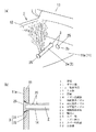
図1に示すように、便器1は、ボウル部11と、ボウル部11の上端に形成されるリム部12とを備え、リム部12の上面に起倒自在に載置される便座13および便蓋(図示せず)の後端部がボウル部11の後部の上端部に枢支され、ボウル部11の後方(使用者が便座に着座したときの背面側)の内部に局部洗浄装置本体が収納される。ボウル部11の後部内面11aにはノズル開口3が形成されると共に、ノズル開口3の後方にボウル部11内に連通するノズル収納部14が形成され、局部洗浄装置本体の前端部に設けられる局部洗浄ノズル2が前記ノズル収納部14に配設される。ノズル開口3については後で詳述する。
As shown in FIG. 1, the
局部洗浄装置本体は、図2に示すように、水道等の水源4と前記局部洗浄ノズル2とを結んで、その途中に給水弁51と、温水ヒーター52と、給水ポンプ53を設けた給水経路5と、人体の局部を洗剤洗浄するための洗剤を前記給水経路5に供給するための洗剤供給経路61および洗剤供給手段と、前記洗剤供給手段からの洗剤を給水経路5に注入して水と混合するため該給水経路5に配設される洗剤注入口としての洗剤混合分岐栓54と、水が洗剤供給経路61に入ることを防ぐための逆止弁62とを備えている。洗剤供給手段は、洗剤を貯えるためのタンクである洗剤保持部63と、前記洗剤を吸引して洗剤混合分岐栓54に搬送するための洗剤ポンプ64とで構成される。なお、本実施形態ではこのように洗剤を供給するための構成を備えた例として説明するが、特に備えていなくてもよいものである。
As shown in FIG. 2, the local cleaning device main body connects a
局部洗浄ノズル2は、図2に示すように本実施形態では複数設けられていて、例えばお尻を目標として洗浄水(水のみ、または洗剤等の洗剤入りの水)を噴出するお尻洗浄ノズル2aと、女性の局部を目標として洗浄水を噴出するビデ洗浄ノズル2b等が挙げられ、前記複数の局部洗浄ノズル2への洗浄水の流路切換手段2cを備えている。
As shown in FIG. 2, a plurality of
局部洗浄ノズル2は、局部に向けて水を噴出する噴出口20を備え、使用時にノズル収納部14から前進してノズル開口3を介して前方のボウル部11内に突出させるもので、内部が水の流路となるシリンダ部21に突没自在に設けられた本体部22の先端に形成され、便器1に固定されるシリンダ部21に対して本体部22を前方に突没させることで突没自在としてある。シリンダ部21の前方側の端部と本体部22の後端部に形成したフランジ部23間にばね24を介在させて本体部22がシリンダ部21に対して後方に付勢してある。これにより、局部洗浄ノズル2の使用時に、洗浄装置本体内の給水ポンプ53にて局部洗浄ノズル2に温水を搬送する際の水圧にて本体部22のフランジ部23がばね24のばね力に抗して前方に押され、本体部22が前方に伸びることとなる(図3(a)参照)。そして、使用後に温水の搬送を停止すると、ばね24の復元力によって本体部22はノズル開口3を介して後方に後退してノズル収納部14に収納される(図3(b)参照)。
The
そして局部洗浄装置本体の給水弁51と温水ヒーター52と洗剤ポンプ64、操作スイッチ部、流路切換手段2cは制御部に接続されて該制御部によって制御される。
The
使用者は、用を足した後に操作スイッチ部から洗浄方法を入力し、例えば洗浄操作キーを操作して「水洗浄」を選択した場合には、洗剤ポンプ64は停止した状態で水源4から水が給水経路5を通って局部洗浄ノズル2より人体局部に噴出され、剤洗浄開始操作キーを操作して「洗剤洗浄」を入力した場合には、洗剤ポンプ64を駆動した状態で、上記洗剤混合分岐栓54から洗剤が混入されて洗剤入の温水が局部洗浄ノズル2より人体局部に噴出される。
When the user inputs a cleaning method from the operation switch unit after adding the operation, for example, by operating the cleaning operation key and selecting “water cleaning”, the detergent pump 64 is stopped and water is supplied from the
本発明は局部洗浄ノズル2の収納構造に特徴を有するもので、局部洗浄ノズル2とノズル開口3とについて図1(b)に基づいて説明する。
The present invention has a feature in the housing structure of the
局部洗浄ノズル2の前端部には、前後方向に直交する断面積が、局部洗浄ノズル2のボウル部11内に突出する他の部分よりも大きいフランジからなるカバー部25が形成してある。これに対応して、ノズル開口3は、ボウル部11の後部内面11aから後方に前記カバー部25の厚みと略同じ長さまでの部分を、断面形状がカバー部25と略同じであるカバー形状部31とすると共に、カバー形状部31の後方に、局部洗浄ノズル2のボウル部11内に突出するカバー部25以外の部分(すなわちシリンダ部21)が挿通され断面積がカバー部25よりも小さい小形部32が設けてある。本実施形態では、ボウル部11は所定の厚みを有していて、ボウル部11の内表面側にカバー形状部31が形成してあり、ボウル部11の裏面側に小形部32が形成してあり、その後方はノズル収納部14を含む局部洗浄装置本体の収納空間となっている。
The front end portion of the
これにより、局部洗浄ノズル2が後退してノズル収納部14に収納された時、カバー部25がノズル開口3のカバー形状部31に収納され、カバー部25の前面がボウル部11の後部内面11aと面一となって、拭き掃除による手入れを容易に行うことができる。
Thereby, when the
また、カバー形状部31の後方に小形部32が形成してあるため、ノズル開口3の内端と局部洗浄ノズル2との間の隙間より汚物等が侵入しても、小形部32でそれ以上の侵入が阻止され、内部まで侵入し難い。
In addition, since the
1 便器
11 ボウル部
11a 後部内面
12 リム部
13 便座
14 ノズル収納部
2 局部洗浄ノズル
2a お尻洗浄ノズル
2b ビデ洗浄ノズル
2c 流路切換手段
20 噴出口
21 シリンダ部
22 本体部
23 フランジ部
24 ばね
25 カバー部
3 ノズル開口
31 カバー形状部
32 小形部
4 水源
5 給水経路
51 給水弁
52 温水ヒーター
53 給水ポンプ
54 洗剤混合分岐栓
61 洗剤供給経路
62 逆止弁
63 洗剤保持部
64 洗剤ポンプ
DESCRIPTION OF
Claims (1)
Priority Applications (1)
| Application Number | Priority Date | Filing Date | Title |
|---|---|---|---|
| JP2009041482A JP5167166B2 (en) | 2009-02-24 | 2009-02-24 | Local cleaning equipment |
Applications Claiming Priority (1)
| Application Number | Priority Date | Filing Date | Title |
|---|---|---|---|
| JP2009041482A JP5167166B2 (en) | 2009-02-24 | 2009-02-24 | Local cleaning equipment |
Publications (2)
| Publication Number | Publication Date |
|---|---|
| JP2010196332A JP2010196332A (en) | 2010-09-09 |
| JP5167166B2 true JP5167166B2 (en) | 2013-03-21 |
Family
ID=42821319
Family Applications (1)
| Application Number | Title | Priority Date | Filing Date |
|---|---|---|---|
| JP2009041482A Expired - Fee Related JP5167166B2 (en) | 2009-02-24 | 2009-02-24 | Local cleaning equipment |
Country Status (1)
| Country | Link |
|---|---|
| JP (1) | JP5167166B2 (en) |
Family Cites Families (1)
| Publication number | Priority date | Publication date | Assignee | Title |
|---|---|---|---|---|
| JPS59151987U (en) * | 1983-03-30 | 1984-10-11 | アイシン精機株式会社 | Human body private parts cleaning device |
-
2009
- 2009-02-24 JP JP2009041482A patent/JP5167166B2/en not_active Expired - Fee Related
Also Published As
| Publication number | Publication date |
|---|---|
| JP2010196332A (en) | 2010-09-09 |
Similar Documents
| Publication | Publication Date | Title |
|---|---|---|
| JP5467528B2 (en) | Sanitary washing device | |
| JP2001254425A (en) | Sanitary washing equipment | |
| JP2008223244A (en) | Nozzle device and sanitary washing device provided with the same | |
| JP2010196375A (en) | Flush toilet bowl | |
| JP6075697B2 (en) | Sanitary washing device | |
| JP7340437B2 (en) | Private cleaning device and flush toilet | |
| JP5167166B2 (en) | Local cleaning equipment | |
| JP5354453B2 (en) | Flush toilet | |
| JP5682834B2 (en) | Sanitary washing device | |
| JP4591540B2 (en) | Nozzle device and sanitary washing device using it | |
| JP2009007849A (en) | Human body local cleaning equipment | |
| JP2018028193A (en) | Sanitary washing device | |
| KR20160012363A (en) | Cleaning device for toilet seat | |
| JP6515464B2 (en) | Human body part cleaning device | |
| JP2013032645A (en) | Hot water washing device and toilet bowl device | |
| JP5660338B2 (en) | Sanitary washing device | |
| JP4403879B2 (en) | Hot water flush toilet | |
| JP2004263397A (en) | Toilet flushing device | |
| KR102212013B1 (en) | Nozzle Assembly for Bidet and Bidet Including the Same | |
| JP4832788B2 (en) | Sanitary washing toilet seat device and toilet device | |
| JP6175595B2 (en) | Toilet seat with washing function | |
| JP2001081838A (en) | Hot water washing device | |
| JP4840194B2 (en) | Sanitary washing device | |
| JP2005325512A (en) | Local cleaner | |
| JP5884587B2 (en) | Toilet seat device |
Legal Events
| Date | Code | Title | Description |
|---|---|---|---|
| RD04 | Notification of resignation of power of attorney |
Free format text: JAPANESE INTERMEDIATE CODE: A7424 Effective date: 20100715 |
|
| A621 | Written request for application examination |
Free format text: JAPANESE INTERMEDIATE CODE: A621 Effective date: 20110125 |
|
| A711 | Notification of change in applicant |
Free format text: JAPANESE INTERMEDIATE CODE: A712 Effective date: 20120113 |
|
| A131 | Notification of reasons for refusal |
Free format text: JAPANESE INTERMEDIATE CODE: A131 Effective date: 20120904 |
|
| A977 | Report on retrieval |
Free format text: JAPANESE INTERMEDIATE CODE: A971007 Effective date: 20120905 |
|
| A521 | Request for written amendment filed |
Free format text: JAPANESE INTERMEDIATE CODE: A523 Effective date: 20121105 |
|
| TRDD | Decision of grant or rejection written | ||
| A01 | Written decision to grant a patent or to grant a registration (utility model) |
Free format text: JAPANESE INTERMEDIATE CODE: A01 Effective date: 20121127 |
|
| A61 | First payment of annual fees (during grant procedure) |
Free format text: JAPANESE INTERMEDIATE CODE: A61 Effective date: 20121221 |
|
| FPAY | Renewal fee payment (event date is renewal date of database) |
Free format text: PAYMENT UNTIL: 20151228 Year of fee payment: 3 |
|
| R150 | Certificate of patent or registration of utility model |
Ref document number: 5167166 Country of ref document: JP Free format text: JAPANESE INTERMEDIATE CODE: R150 Free format text: JAPANESE INTERMEDIATE CODE: R150 |
|
| LAPS | Cancellation because of no payment of annual fees |