JP5166532B2 - Shoulder brace - Google Patents
Shoulder brace Download PDFInfo
- Publication number
- JP5166532B2 JP5166532B2 JP2010518144A JP2010518144A JP5166532B2 JP 5166532 B2 JP5166532 B2 JP 5166532B2 JP 2010518144 A JP2010518144 A JP 2010518144A JP 2010518144 A JP2010518144 A JP 2010518144A JP 5166532 B2 JP5166532 B2 JP 5166532B2
- Authority
- JP
- Japan
- Prior art keywords
- shoulder
- arm cuff
- user
- cuff
- upper arm
- Prior art date
- Legal status (The legal status is an assumption and is not a legal conclusion. Google has not performed a legal analysis and makes no representation as to the accuracy of the status listed.)
- Active
Links
- 210000000323 shoulder joint Anatomy 0.000 claims abstract description 5
- 239000000463 material Substances 0.000 claims description 7
- 239000013013 elastic material Substances 0.000 claims description 2
- 239000006261 foam material Substances 0.000 claims description 2
- 229920001084 poly(chloroprene) Polymers 0.000 claims description 2
- 230000001737 promoting effect Effects 0.000 claims 1
- 238000010586 diagram Methods 0.000 description 5
- 230000000694 effects Effects 0.000 description 5
- 238000000034 method Methods 0.000 description 2
- 206010021118 Hypotonia Diseases 0.000 description 1
- 206010028391 Musculoskeletal Pain Diseases 0.000 description 1
- 208000007613 Shoulder Pain Diseases 0.000 description 1
- 239000004433 Thermoplastic polyurethane Substances 0.000 description 1
- 210000002310 elbow joint Anatomy 0.000 description 1
- 239000000835 fiber Substances 0.000 description 1
- 239000013305 flexible fiber Substances 0.000 description 1
- 210000003205 muscle Anatomy 0.000 description 1
- 230000036640 muscle relaxation Effects 0.000 description 1
- 239000012782 phase change material Substances 0.000 description 1
- 210000001991 scapula Anatomy 0.000 description 1
- 229920002379 silicone rubber Polymers 0.000 description 1
- 239000004945 silicone rubber Substances 0.000 description 1
- 230000006641 stabilisation Effects 0.000 description 1
- 238000011105 stabilization Methods 0.000 description 1
- 230000004936 stimulating effect Effects 0.000 description 1
- 239000000758 substrate Substances 0.000 description 1
- 208000024891 symptom Diseases 0.000 description 1
- 229920002994 synthetic fiber Polymers 0.000 description 1
- 229920002803 thermoplastic polyurethane Polymers 0.000 description 1
Images


Classifications
-
- A—HUMAN NECESSITIES
- A61—MEDICAL OR VETERINARY SCIENCE; HYGIENE
- A61F—FILTERS IMPLANTABLE INTO BLOOD VESSELS; PROSTHESES; DEVICES PROVIDING PATENCY TO, OR PREVENTING COLLAPSING OF, TUBULAR STRUCTURES OF THE BODY, e.g. STENTS; ORTHOPAEDIC, NURSING OR CONTRACEPTIVE DEVICES; FOMENTATION; TREATMENT OR PROTECTION OF EYES OR EARS; BANDAGES, DRESSINGS OR ABSORBENT PADS; FIRST-AID KITS
- A61F5/00—Orthopaedic methods or devices for non-surgical treatment of bones or joints; Nursing devices; Anti-rape devices
- A61F5/37—Restraining devices for the body or for body parts, e.g. slings; Restraining shirts
- A61F5/3715—Restraining devices for the body or for body parts, e.g. slings; Restraining shirts for attaching the limbs to other parts of the body
- A61F5/3723—Restraining devices for the body or for body parts, e.g. slings; Restraining shirts for attaching the limbs to other parts of the body for the arms
-
- A—HUMAN NECESSITIES
- A61—MEDICAL OR VETERINARY SCIENCE; HYGIENE
- A61F—FILTERS IMPLANTABLE INTO BLOOD VESSELS; PROSTHESES; DEVICES PROVIDING PATENCY TO, OR PREVENTING COLLAPSING OF, TUBULAR STRUCTURES OF THE BODY, e.g. STENTS; ORTHOPAEDIC, NURSING OR CONTRACEPTIVE DEVICES; FOMENTATION; TREATMENT OR PROTECTION OF EYES OR EARS; BANDAGES, DRESSINGS OR ABSORBENT PADS; FIRST-AID KITS
- A61F5/00—Orthopaedic methods or devices for non-surgical treatment of bones or joints; Nursing devices; Anti-rape devices
- A61F5/01—Orthopaedic devices, e.g. splints, casts or braces
- A61F5/0102—Orthopaedic devices, e.g. splints, casts or braces specially adapted for correcting deformities of the limbs or for supporting them; Ortheses, e.g. with articulations
- A61F5/0104—Orthopaedic devices, e.g. splints, casts or braces specially adapted for correcting deformities of the limbs or for supporting them; Ortheses, e.g. with articulations without articulation
- A61F5/0118—Orthopaedic devices, e.g. splints, casts or braces specially adapted for correcting deformities of the limbs or for supporting them; Ortheses, e.g. with articulations without articulation for the arms, hands or fingers
-
- A—HUMAN NECESSITIES
- A61—MEDICAL OR VETERINARY SCIENCE; HYGIENE
- A61F—FILTERS IMPLANTABLE INTO BLOOD VESSELS; PROSTHESES; DEVICES PROVIDING PATENCY TO, OR PREVENTING COLLAPSING OF, TUBULAR STRUCTURES OF THE BODY, e.g. STENTS; ORTHOPAEDIC, NURSING OR CONTRACEPTIVE DEVICES; FOMENTATION; TREATMENT OR PROTECTION OF EYES OR EARS; BANDAGES, DRESSINGS OR ABSORBENT PADS; FIRST-AID KITS
- A61F5/00—Orthopaedic methods or devices for non-surgical treatment of bones or joints; Nursing devices; Anti-rape devices
- A61F5/01—Orthopaedic devices, e.g. splints, casts or braces
- A61F5/04—Devices for stretching or reducing fractured limbs; Devices for distractions; Splints
- A61F5/05—Devices for stretching or reducing fractured limbs; Devices for distractions; Splints for immobilising
- A61F5/058—Splints
- A61F5/05841—Splints for the limbs
- A61F5/05858—Splints for the limbs for the arms
Abstract
Description
本発明は、請求項1のプレアンブルに記載の肩装具に関する。 The present invention relates to a shoulder brace according to the preamble of claim 1.
そのような肩装具は、市場では知られており、肩の痛み及び肩領域における機能の低下などの兆候を有する患者を対象としている。 Such shoulder orthoses are known in the market and are intended for patients with symptoms such as shoulder pain and reduced function in the shoulder region.
この装具の目的は、肩部分の緩和をもたらし、患者が運動能力を低下させることも懸念して腕の可動性を増大させることである。 The purpose of this brace is to provide shoulder relaxation and increase arm mobility, also worrying that the patient may lose exercise capacity.
従来知られている肩装具に関する1つの問題は、調整可能性が限定されてしまい、ユーザの運動の自由が減じてしまうことである。そのため、従来知られている肩装具は、上記で挙げた条件において、適切な支持及び緩和を完全には与えていない。 One problem with conventionally known shoulder braces is that the adjustability is limited and the user's freedom of movement is reduced. Therefore, conventionally known shoulder braces do not provide adequate support and relaxation completely under the conditions listed above.
背景技術の例として、米国特許第5020521号及びFR20530E(1:re Addition au Brevet d’Invention No:486552)を挙げることができる。これらの文献は、支持装置について記載しているが、これらの装置は、十分な柔軟性及び調整可能性があるわけではない。 Examples of background art include US Pat. No. 5,020,521 and FR20530E (1: re Addition au Brevet d'Invention No: 486655). Although these documents describe support devices, these devices are not sufficiently flexible and adjustable.
本発明の目的は、最初に挙げた肩装具であって、背景技術による装置に関する問題が少なくとも減じられる肩装具を提供することである。 The object of the present invention is to provide a shoulder brace that is first mentioned and that at least reduces the problems associated with devices according to the background art.
これは、請求項1の特徴を示す肩装具を用いて達成される。上腕カフを含むことにより、装具全体に対する安定性の増大が得られ、特に支持部分に関しては、それによって支持効果が増大する。 This is achieved with a shoulder brace that exhibits the features of claim 1. Inclusion of the upper arm cuff provides increased stability for the entire brace, particularly for the support portion, thereby increasing the support effect.
引っ張りバンドを介して上腕カフに連結された下腕カフを更に配置することにより、ユーザに対して運動の自由の増大が達成され、それと同時に腕に対して良好な支持が与えられる。支持部分及び上腕カフが一体ユニットであることにより、簡単な操作及び高度な安定性が達成される。少なくとも1つの調整可能な引っ張りバンドが支持部分と上腕カフの間に配置されていることにより、装具のこの部分においても有利な調整機能が可能になる。 By further placing a lower arm cuff connected to the upper arm cuff via a pull band, increased freedom of movement is achieved for the user while at the same time providing good support for the arm. Due to the integral part of the support part and the upper arm cuff, simple operation and high stability are achieved. The at least one adjustable tension band is arranged between the support part and the upper arm cuff, so that an advantageous adjustment function is also possible in this part of the brace.
胸バンド、下腕カフ、上腕カフ及び引っ張りバンドの少なくともいずれかが、調整可能であることが好ましい。これにより、単一ユーザに合わせた調整に対して良好な調整可能性が与えられる。 It is preferred that at least one of the chest band, the lower arm cuff, the upper arm cuff and the tension band is adjustable. This gives good adjustment possibilities for adjustments tailored to a single user.
また、前記引っ張りバンドの数が、2つであり、良好な運動の自由及び腕の運動に影響を及ぼす可能性にとって、前方及び後方領域それぞれから始まることも好ましい。 It is also preferred that the number of pull bands is two and starts from the front and rear regions, respectively, for good freedom of movement and the possibility of affecting arm movement.
更に、後方領域内の支持部分が、ユーザの肩部分に対する作用のための内側に位置決めされた取り外し可能な圧力パッドを置く手段を提供することが好ましい。 Furthermore, it is preferred that the support portion in the posterior region provides a means of placing a removable pressure pad positioned inward for action on the user's shoulder portion.
装具が、ユーザの肩領域に対する作用のための圧力パッドを含むことが好ましい。 Preferably, the brace includes a pressure pad for action on the shoulder area of the user.
さらなる特徴及び利点は、以下の実施例の説明によって明確にされる、本発明のさらなる特徴によって得られる。 Further features and advantages will be gained by the further features of the present invention which will be clarified by the description of the following examples.
次いで、実施例により、付属の図面を参照して本発明をより詳細に説明する。 The invention will now be described in more detail by way of example with reference to the accompanying drawings.
図1では、ユーザの肩領域に位置決めし、そこを取り囲むための支持部分2を含む肩装具1が、基板上に置かれている。支持部分2は、ユーザの肩関節の前方に位置決めされることが意図された前方域と、肩関節の後方に位置決めされることが意図され、背骨を越えて背中上を延びる後方領域4とを含む。
In FIG. 1, a shoulder brace 1 comprising a
後方領域は、支持部分の主要部から先細になっており、ユーザの背中の幅の大部分にほぼ相当する長さを有する。 The rear region is tapered from the main portion of the support portion and has a length substantially corresponding to the majority of the width of the user's back.
5は胸バンドを示し、この胸バンドは、使用中、第2の腕の腋窩下方でユーザの胸周りを胸バンド5が延びるように前方域3と後方域4の自由端を相互連結する。
胸バンドは、個々に適合した装着を容易に提供するために、ベルクロ(Velcro)(c)ファスナー装置を用いることによって締め付けることができる。 The chest band can be tightened by using a Velcro (c) fastener device to easily provide a personalized fit.
上腕カフ7は、支持部分2と一体化され、使用中、ユーザの上腕の一部に沿って延び、また、ベルクロ(C)ファスナー装置が設けられた締め付け手段を有する。図示する実例では、締め付け手段は、肩から離れるように向けられた上腕カフ7の自由部分において位置決めされる。
The
下腕カフは6で示される。上腕カフ7のように、下腕カフには、ユーザの下腕に対して締め付けられるのを目的として、調整可能手段が設けられる。上腕カフ7のように、下腕カフ6は、使用中、患者によって着用される位置において管状形状を有する。締め付け手段は、それぞれのカフをそれぞれの腕部分の周りに締め付けることを目的とする。
The lower arm cuff is indicated by 6. Like the
下腕カフ6は、原理上、それぞれのカフ上で互いに対して対角線上に配置された2つの引っ張りバンド上で上腕カフ7と相互連結される。引っ張りバンド8には、ベルクロ(C)ファスナー装置が設けられ、またこれは、それぞれのユーザに容易に適合させるように調整可能である。
The
9は、上腕カフ7の前側と支持部分の前方域の間で作用する引っ張りバンドを示している。図1には示していない対応する引っ張りバンドが、上腕カフ7の後方部分上に、その上部が支持部分の後方域にある状態で配置される(図5の要素9’を参照)。これらの引っ張りバンドにより、調整の微調節が可能になる。
安定化バンド10は、装具の使用中、ユーザの肩の上方で前方領域と後方領域の間を延びる。
支持部分2の後方域の延長部分上には、圧力パッドと協働することが意図された繊維ヤードの自由設定ループを備えた内方向に向く部分(inwardly directly portion)11が配置される。図2a及び2bでは、そのような圧力パッド12が示されており、この圧力パッド12には、固定域11内で前記自由設定ループと協働するためのベルクロ(C)ファスナー装置が後側13上に設けられる。
An inwardly directed portion 11 with a free setting loop of the fiber yard intended to cooperate with the pressure pad is arranged on the extension in the rear region of the
パッド12は、表面上に分布させたいくつかの圧力ボスを備えた接触表面を有する。図示するパッド12上には、4つのそのような圧力ボスが配置され、これらの圧力ボスは、刺激を与える目的でユーザの肩部分に対して作用する機能を有する。特に、刺激は、患者の肩甲骨と背骨の間の衰えた筋肉に対するものである。
The
図3〜7は、ユーザに本発明による肩装具を位置決めするプロセスを示すことが意図されている。図3では、肩装具1は、ユーザの肩に着用されており、支持部分の初期位置はその使用位置よりも幾分下方にある状態である。破線Aは、いわゆる関節の溝を示している。上腕カフにおける縫い目Bは、調整された位置、すなわち使用中、線Aにほぼ沿っていなければならない。上腕カフ7は、ユーザの上腕の周りにベルクロバンドが設けられた重複する引っ張りバンドを用いることによって締め付けられる。
3-7 are intended to illustrate the process of positioning a shoulder brace according to the present invention to a user. In FIG. 3, the shoulder brace 1 is worn on the user's shoulder, and the initial position of the support portion is somewhat below the use position. A broken line A indicates a so-called joint groove. The seam B in the upper arm cuff should be approximately along line A in the adjusted position, ie in use. The
図4では、ユーザの胸の前側における胸バンド5の締め付け及び調整が示されている。
FIG. 4 shows tightening and adjustment of the
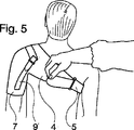
図5は、胸バンドの後方部分における締め付けの調整を示している。この調整及び関連する締め付けの構成は、任意選択である。 FIG. 5 shows the adjustment of the tightening in the rear part of the chest band. This adjustment and associated tightening configuration is optional.
全体では、胸バンド5を引っ張ることにより、支持部分2が内方向及び上方向に引き上げられ、それによって上腕を含む肩部分全体が持ち上げられる結果となる。
Overall, pulling the
図6では、図示した位置において、ユーザの下腕に締め付けられ、固定された下腕カフ6が示されている。更に、上腕カフ及び下腕カフそれぞれの各側における引っ張りバンド8の締め付けが示されている。この目的は、ユーザの下腕の高い可動性を維持しながら、肘関節及び下腕を制御する筋肉の緩和を得ることである。
FIG. 6 shows the
図示する実例では2つの引っ張りバンドである引っ張りバンドを備えて構築することにより、下腕カフの位置を個々に調整する機会が極めて多くなることに留意されねばならない。引っ張りバンドの位置決めにより、実際には、上腕カフに対する下腕カフの回転位置が、下腕に対する所望のねじり効果を達成するような可能性を更にもたらす。通常、概して下腕カフの外方向の回転効果が望ましく、それによって支持部分及び肩に対する腕全体の外方向の回転効果が望ましい。 It should be noted that by constructing with two pull bands, which are the pull bands in the illustrated example, the opportunity to individually adjust the position of the lower arm cuff is greatly increased. By positioning the tension band, in fact, the rotational position of the lower arm cuff relative to the upper arm cuff further provides the possibility of achieving the desired torsional effect on the lower arm. Generally, the outward rotation effect of the lower arm cuff is generally desirable, thereby the outward rotation effect of the entire arm relative to the support portion and the shoulder.
図7は、装具の最終調整を達成するための締め付けバンド9、9’の締め付けを示している。
FIG. 7 shows the clamping of the clamping
3〜7の順序の図では、装具の装着が補助されているユーザが示されている。患者が重度の身体障害者である場合、これが通常の手順である。しかし、数多くの患者が、本発明による肩装具の位置決め及び取り外しを自身で操作できることは除外されない。 In the figure of the order of 3-7, the user who is assisting the wearing of the brace is shown. This is the normal procedure if the patient is a severely disabled person. However, it is not excluded that many patients can manipulate the positioning and removal of shoulder braces according to the present invention themselves.
本発明は、特許請求の範囲内で改変することができる。したがって、締め付け機能を別の方法で、協働するベルクロ(C)ファスナー装置を備えたバンド、たとえベルクロ(C)ファスナー装置が本発明に関して好ましい場合でも、たとえば従来のバンド・バックルを備えたバンドによって達成することができる。しかし、本発明による装具が、全体的に個々のユーザに適合されることは除外されず、それによってそのような場合、調節機能の可能性に対する必要性を、上記で示した締め付け可能な個々の要素の1つ又は複数に関して除外することができる。 The invention can be modified within the scope of the claims. Thus, a band with a cooperating Velcro (C) fastener device, even if a Velcro (C) fastener device is preferred in the context of the present invention, for example by a band with a conventional band buckle. Can be achieved. However, it is not excluded that the brace according to the invention is totally adapted to the individual user, so that in such cases the need for the possibility of an adjustment function is indicated by the tightenable individual shown above. It can be excluded for one or more of the elements.
支持部分は、圧力パッドの固定域を有さずに構築することができ、支持部分の一体ユニットではない上腕カフを構成することも可能である。しかし、この解決策は、本発明に関しては好ましくない。装具は、下腕カフが連結されない状態で使用できることにも留意されねばならない。 The support portion can be constructed without having a fixed area of the pressure pad, and can also constitute an upper arm cuff that is not an integral unit of the support portion. However, this solution is not preferred with respect to the present invention. It should also be noted that the brace can be used without the lower arm cuff being connected.
肩装具の(バンドなどを除く)主要部は、運動を促進する装具に対する支持を伴った状態で所望の運動の自由を達成するために、適切な弾性材料から作製されねばならない。そのような材料は、たとえば、弾性のいわゆる3D材料又は弾性のネオプレン・ゴムでよく、支持部分並びに上腕カフ及び下腕カフの内側並びに外側では適切な柔軟性の繊維材料で積層することができる。たとえばPCM発泡材料などの弾性のPCM材料を含有する層(相変化材料)を、温度調節効果を可能にするために役立てることが好ましい。パッドは、数多くのさまざまな合成材料から製造されてよい。1つの例は、熱可塑性ポリウレタンである。 The main part of the shoulder brace (except the band etc.) must be made of a suitable elastic material in order to achieve the desired freedom of movement with support for the brace that facilitates movement. Such a material may be, for example, an elastic so-called 3D material or elastic neoprene rubber and may be laminated with a suitable flexible fiber material on the inside and outside of the support portion and upper and lower arm cuffs. Preferably, a layer (phase change material) containing an elastic PCM material, such as a PCM foam material, serves to enable a temperature control effect. The pad may be made from a number of different synthetic materials. One example is thermoplastic polyurethane.
通常、縁に近接する、肩関節から最も遠いカフの内側では、カフと腕の部分の間を滑る傾向を減じるために、摩擦を増大させるシリコン・ゴムのストリップが配置されることが好ましい。 Normally, inside the cuff furthest from the shoulder joint, close to the edge, it is preferable to place a strip of silicone rubber that increases friction to reduce the tendency to slip between the cuff and the arm portion.
Claims (8)
前記前方域及び後方域に連結し、使用中、ユーザの胸の周りを延びる胸バンド(5)と、
前記ユーザの前記肩に関連する腕の周りに装着するための腕カフと、
前記支持部分と前記腕カフを連結するための引っ張りバンドと、
前記腕の上腕の周りに装着するための上腕カフ(7)とを含み、
前記腕カフが、下腕の周りに位置決めするための下腕カフ(6)であり、
前記引っ張りバンド(8)が、前記上腕カフ(7)と前記下腕カフ(6)を連結するように配置されている、肩装具(1)において、
前記支持部分(2)が、前記上腕カフ(7)を含み、
前記支持部分(2)及び前記上腕カフ(7)が、一体ユニットを形成し、
少なくとも1つの調整可能な引っ張りバンド(9、9’)が、前記支持部分(2)と前記上腕カフ(7)の間に配置されることを特徴とする、肩装具(1)。A support portion (2) for positioning above a user's shoulder, wherein in use, an anterior portion (3) and a posterior portion (shaped) that are configured to be positioned respectively in front of and behind the shoulder joint of the shoulder A support part (2) with 4);
A chest band (5) connected to the anterior and posterior regions and extending around the user's chest during use;
An arm cuff for wearing around an arm associated with the shoulder of the user;
A tension band for connecting the support portion and the arm cuff;
An upper arm cuff (7) for wearing around the upper arm of the arm,
The arm cuff is a lower arm cuff (6) for positioning around the lower arm;
In the shoulder brace (1), wherein the tension band (8) is arranged to connect the upper arm cuff (7) and the lower arm cuff (6),
The support portion (2) includes the upper arm cuff (7);
The support portion (2) and the upper arm cuff (7) form an integral unit;
Shoulder orthosis (1), characterized in that at least one adjustable tension band (9, 9 ') is arranged between the support part (2) and the upper arm cuff (7).
Applications Claiming Priority (3)
| Application Number | Priority Date | Filing Date | Title |
|---|---|---|---|
| SE0701792A SE532475C2 (en) | 2007-07-27 | 2007-07-27 | Shoulder orthosis |
| SE0701792-4 | 2007-07-27 | ||
| PCT/SE2008/000452 WO2009017442A1 (en) | 2007-07-27 | 2008-07-16 | Shoulder orthosis |
Publications (3)
| Publication Number | Publication Date |
|---|---|
| JP2010534507A JP2010534507A (en) | 2010-11-11 |
| JP2010534507A5 JP2010534507A5 (en) | 2011-09-08 |
| JP5166532B2 true JP5166532B2 (en) | 2013-03-21 |
Family
ID=40304554
Family Applications (1)
| Application Number | Title | Priority Date | Filing Date |
|---|---|---|---|
| JP2010518144A Active JP5166532B2 (en) | 2007-07-27 | 2008-07-16 | Shoulder brace |
Country Status (8)
| Country | Link |
|---|---|
| US (1) | US10485692B2 (en) |
| EP (1) | EP2175816B1 (en) |
| JP (1) | JP5166532B2 (en) |
| CN (1) | CN101808600B (en) |
| AT (1) | ATE536840T1 (en) |
| PL (1) | PL2175816T3 (en) |
| SE (1) | SE532475C2 (en) |
| WO (1) | WO2009017442A1 (en) |
Families Citing this family (24)
| Publication number | Priority date | Publication date | Assignee | Title |
|---|---|---|---|---|
| GB0900939D0 (en) * | 2009-01-21 | 2009-03-04 | Nhs South West Essex | Shoulder stabilising device |
| US10179075B1 (en) * | 2010-04-07 | 2019-01-15 | Shawn Hickling | Shoulder thermal therapy wrap |
| DE102010026240A1 (en) * | 2010-07-01 | 2012-01-05 | Otto Bock Healthcare Gmbh | Orthosis with at least one textile bandage |
| IT1402766B1 (en) * | 2010-11-29 | 2013-09-18 | Fond Salvatore Maugeri Clinica Del Lavoro E Della | TUTOR FOR THE SHOULDER. |
| USD667956S1 (en) * | 2011-04-26 | 2012-09-25 | Pang-Ching Chiang | Shoulder support |
| CN102784022B (en) * | 2012-08-13 | 2014-04-30 | 易民 | Structure of eyelet installation hole in orthopedic appliance of low temperature thermoplastic plate |
| US11638656B2 (en) | 2012-12-31 | 2023-05-02 | Xtreme Orthopedics Llc | Shoulder and arm restraint |
| US10398585B2 (en) | 2013-05-30 | 2019-09-03 | Xtreme Orthopedics Llc | Shoulder and arm restraint |
| USD962450S1 (en) | 2013-05-30 | 2022-08-30 | Extreme Orthopedics Llc | Shoulder immobilizer pillow |
| US9782285B1 (en) * | 2013-09-27 | 2017-10-10 | Weber Orthopedic, Inc. | Elbow-forearm anti-rotation orthosis |
| DE102015112406B4 (en) | 2015-07-29 | 2017-02-09 | Otto Bock Healthcare Products Gmbh | Prosthetic shaft holding device and system of prosthesis shaft and prosthesis shaft retaining device |
| US10285841B2 (en) * | 2015-09-04 | 2019-05-14 | Rojan John Pappady | Stabilizing and mobility-enhancing brace for the shoulder joint |
| WO2017066430A1 (en) * | 2015-10-13 | 2017-04-20 | Lakkireddy Dhanunjaya | Cardiac implantable electronic device pocket compression apparatus and method of mitigating localized bleeding using same |
| US20220125438A1 (en) * | 2015-10-13 | 2022-04-28 | Dhanunjaya Lakkireddy | Cardiac implantable electronic device pocket compression apparatus and method of mitigating localized bleeding using same |
| US11412794B2 (en) * | 2016-02-29 | 2022-08-16 | Alignmed, Inc. | Limb sleeves for body alignment |
| US10646366B2 (en) * | 2016-04-01 | 2020-05-12 | Silas Efraim Bezerra de Araujo Pimentel | Functional shoulder support brace with cabling system |
| US11052301B2 (en) | 2016-04-07 | 2021-07-06 | Nike, Inc. | Securing garment for a shoulder-pad system |
| US10646769B1 (en) | 2016-04-07 | 2020-05-12 | Nike, Inc. | Discrete shoulder sleeve for a shoulder-pad system |
| US11000755B2 (en) | 2016-04-07 | 2021-05-11 | Nike, Inc. | Impact-attenuation sub-layer for a shoulder-pad system |
| EP3235474A1 (en) * | 2016-04-18 | 2017-10-25 | Roessingh Beheer B.V. | Shoulder brace |
| KR101892657B1 (en) * | 2016-08-16 | 2018-08-28 | 주식회사 에프엠에스코리아 | PCM package for wearing |
| USD849255S1 (en) * | 2017-10-18 | 2019-05-21 | Jason Colleran | Arm sleeve |
| CN108567517A (en) * | 2018-05-02 | 2018-09-25 | 芜湖普敦特医疗器械有限公司 | Chinese medicine plintlet shoulder joint external fixer |
| USD982165S1 (en) * | 2022-03-24 | 2023-03-28 | Xicun Qin | Knee massager |
Family Cites Families (29)
| Publication number | Priority date | Publication date | Assignee | Title |
|---|---|---|---|---|
| FR20530E (en) * | 1916-04-14 | 1918-05-08 | Hubert De Boutray | Gauntlet to cure radial palsy |
| JPS5215109Y2 (en) * | 1973-07-16 | 1977-04-05 | ||
| US5020521A (en) * | 1982-11-10 | 1991-06-04 | Salort Guy J | External apparatus for motor handicaps of at least one upper limb |
| FR2535604A1 (en) * | 1982-11-10 | 1984-05-11 | Salort Guy | EXTERNAL APPARATUS FOR DISABLED MOTORS OF AT LEAST ONE TOP MEMBER |
| JPS60129044A (en) * | 1983-12-19 | 1985-07-10 | ギ−,サロ−ル | Exterior tool for motion muscle obstacle |
| DE3521796A1 (en) * | 1985-06-19 | 1987-01-02 | Kolbenschmidt Ag | PISTON PIN |
| US4753240A (en) * | 1986-05-13 | 1988-06-28 | Sparks Danny R | Device for immobilizing and applying heat or cold to a body joint |
| US5235675A (en) * | 1989-06-26 | 1993-08-10 | Oki Electric Industry Co., Ltd. | Printer control system for controlling printers differing from each other in dot density |
| JPH0411013U (en) * | 1990-05-16 | 1992-01-29 | ||
| DE9010801U1 (en) * | 1990-07-20 | 1990-09-27 | Bauerfeind Gmbh & Co, 4152 Kempen, De | |
| US5188587A (en) * | 1991-06-07 | 1993-02-23 | Mcguire Robert R | Active shoulder brace |
| US5235975A (en) * | 1992-01-13 | 1993-08-17 | Pressure Products Medical Supplies, Inc. | Cardiac pacemaker compression harness |
| DE9215341U1 (en) | 1992-11-11 | 1993-01-14 | Ferd. Hauber Gmbh & Co Kg, 7440 Nuertingen, De | |
| DE4316047A1 (en) * | 1993-05-13 | 1994-11-17 | Karsten Gehle | Shoulder subluxation orthesis |
| US5403268A (en) * | 1993-10-25 | 1995-04-04 | Med-Techna, Inc. | Arm support |
| US5628725A (en) * | 1995-03-21 | 1997-05-13 | The Saunders Group, Inc. | Shoulder stabilizer methods |
| JP3035558U (en) * | 1996-08-07 | 1997-03-28 | 川村義肢株式会社 | Shoulder joint orthosis |
| US6113562A (en) * | 1998-06-01 | 2000-09-05 | Peter M. Bonutti | Shoulder orthosis |
| EP1107712A4 (en) * | 1998-07-31 | 2004-12-01 | Bruce G Kania | Shoulder brace |
| US6709411B1 (en) * | 1999-03-18 | 2004-03-23 | David R. Olinger | Shoulder brace, and methods of use |
| US6152891A (en) * | 1999-08-19 | 2000-11-28 | Carlson; Greg | Human shoulder brace |
| US7135005B2 (en) * | 2001-02-20 | 2006-11-14 | Fountainhead, Llc | Shoulder brace |
| DE20114446U1 (en) * | 2001-07-20 | 2001-11-29 | Gesundheitspark Beelitz Gmbh | Functional shoulder bandage |
| JP2003265670A (en) * | 2002-03-12 | 2003-09-24 | Univ Nihon | Shoulder supporter |
| CN2558025Y (en) * | 2002-07-05 | 2003-06-25 | 徐庚平 | Bodily form corrector |
| AU2002953422A0 (en) * | 2002-12-18 | 2003-01-09 | Sonnabend, David H. | A device for treatment of a shoulder injury |
| EP1609451A4 (en) * | 2003-03-28 | 2010-02-10 | Univ Tokyo Science | Wear-type joint drive device |
| JP3107406U (en) * | 2004-08-26 | 2005-02-03 | 株式会社メディックス | Shoulder joint orthosis |
| US20080208092A1 (en) * | 2007-02-26 | 2008-08-28 | Sawa Thomas M | Shoulder brace traction system |
-
2007
- 2007-07-27 SE SE0701792A patent/SE532475C2/en not_active IP Right Cessation
-
2008
- 2008-07-16 AT AT08779231T patent/ATE536840T1/en active
- 2008-07-16 CN CN200880100736.9A patent/CN101808600B/en active Active
- 2008-07-16 PL PL08779231T patent/PL2175816T3/en unknown
- 2008-07-16 EP EP08779231A patent/EP2175816B1/en active Active
- 2008-07-16 US US12/670,790 patent/US10485692B2/en active Active
- 2008-07-16 WO PCT/SE2008/000452 patent/WO2009017442A1/en active Application Filing
- 2008-07-16 JP JP2010518144A patent/JP5166532B2/en active Active
Also Published As
| Publication number | Publication date |
|---|---|
| ATE536840T1 (en) | 2011-12-15 |
| EP2175816A4 (en) | 2010-07-21 |
| US20100210985A1 (en) | 2010-08-19 |
| WO2009017442A1 (en) | 2009-02-05 |
| EP2175816A1 (en) | 2010-04-21 |
| US10485692B2 (en) | 2019-11-26 |
| SE0701792L (en) | 2009-01-28 |
| CN101808600B (en) | 2014-04-09 |
| JP2010534507A (en) | 2010-11-11 |
| EP2175816B1 (en) | 2011-12-14 |
| CN101808600A (en) | 2010-08-18 |
| SE532475C2 (en) | 2010-02-02 |
| PL2175816T3 (en) | 2012-05-31 |
Similar Documents
| Publication | Publication Date | Title |
|---|---|---|
| JP5166532B2 (en) | Shoulder brace | |
| US11504257B2 (en) | Adjustable dorsal night splint | |
| US6213968B1 (en) | Custom fitted orthotic device | |
| US8172780B2 (en) | Hip brace apparatus and method of use | |
| US6368295B1 (en) | Non-invasive halo-type cervical brace | |
| US6440094B1 (en) | Orthopedic garment for dynamically enhancing proper posture | |
| US7625350B2 (en) | Glide sleeve brace | |
| KR100883324B1 (en) | A orthopedics for abduction of shoulder joint | |
| US5843010A (en) | Heel and ankle appliance | |
| JP2010269164A (en) | Orthopedic brace suspension system | |
| US10932939B1 (en) | Global osteoarthritis knee brace | |
| EP1372554A2 (en) | Knee strap | |
| WO2011156772A1 (en) | Shoulder and arm orthosis | |
| US20080077066A1 (en) | Lewis lift AFO device | |
| US6110133A (en) | Convertible acromioclavicular stabilizer | |
| US20230338177A1 (en) | Multi-component hip orthosis | |
| US20150057588A1 (en) | Dynamic joint stabilizer | |
| US10206804B1 (en) | Global osteoarthritis knee brace | |
| JP2000037409A (en) | Alkle outfit | |
| WO1992018072A1 (en) | Attachment for leg and foot joint | |
| JP2000037408A (en) | Elbow outfit | |
| JP6360416B2 (en) | Shoulder pain relief device | |
| CN209808666U (en) | T-shaped adjustable correction belt for correcting foot drop and foot inversion during walking | |
| JP2000037407A (en) | Laminated orthopedic outfit | |
| JPH0247937Y2 (en) |
Legal Events
| Date | Code | Title | Description |
|---|---|---|---|
| A521 | Request for written amendment filed |
Free format text: JAPANESE INTERMEDIATE CODE: A523 Effective date: 20110714 |
|
| A621 | Written request for application examination |
Free format text: JAPANESE INTERMEDIATE CODE: A621 Effective date: 20110714 |
|
| A977 | Report on retrieval |
Free format text: JAPANESE INTERMEDIATE CODE: A971007 Effective date: 20121109 |
|
| TRDD | Decision of grant or rejection written | ||
| A01 | Written decision to grant a patent or to grant a registration (utility model) |
Free format text: JAPANESE INTERMEDIATE CODE: A01 Effective date: 20121204 |
|
| A61 | First payment of annual fees (during grant procedure) |
Free format text: JAPANESE INTERMEDIATE CODE: A61 Effective date: 20121220 |
|
| FPAY | Renewal fee payment (event date is renewal date of database) |
Free format text: PAYMENT UNTIL: 20151228 Year of fee payment: 3 |
|
| R150 | Certificate of patent or registration of utility model |
Ref document number: 5166532 Country of ref document: JP Free format text: JAPANESE INTERMEDIATE CODE: R150 Free format text: JAPANESE INTERMEDIATE CODE: R150 |
|
| R250 | Receipt of annual fees |
Free format text: JAPANESE INTERMEDIATE CODE: R250 |
|
| R250 | Receipt of annual fees |
Free format text: JAPANESE INTERMEDIATE CODE: R250 |
|
| R250 | Receipt of annual fees |
Free format text: JAPANESE INTERMEDIATE CODE: R250 |
|
| R250 | Receipt of annual fees |
Free format text: JAPANESE INTERMEDIATE CODE: R250 |
|
| R250 | Receipt of annual fees |
Free format text: JAPANESE INTERMEDIATE CODE: R250 |
|
| R250 | Receipt of annual fees |
Free format text: JAPANESE INTERMEDIATE CODE: R250 |
|
| R250 | Receipt of annual fees |
Free format text: JAPANESE INTERMEDIATE CODE: R250 |
|
| R250 | Receipt of annual fees |
Free format text: JAPANESE INTERMEDIATE CODE: R250 |
|
| R250 | Receipt of annual fees |
Free format text: JAPANESE INTERMEDIATE CODE: R250 |