JP5166274B2 - Parallel optical system - Google Patents
Parallel optical system Download PDFInfo
- Publication number
- JP5166274B2 JP5166274B2 JP2008539123A JP2008539123A JP5166274B2 JP 5166274 B2 JP5166274 B2 JP 5166274B2 JP 2008539123 A JP2008539123 A JP 2008539123A JP 2008539123 A JP2008539123 A JP 2008539123A JP 5166274 B2 JP5166274 B2 JP 5166274B2
- Authority
- JP
- Japan
- Prior art keywords
- sleeve
- lens cell
- housing
- lens
- cell
- Prior art date
- Legal status (The legal status is an assumption and is not a legal conclusion. Google has not performed a legal analysis and makes no representation as to the accuracy of the status listed.)
- Expired - Fee Related
Links
Images


Classifications
-
- G—PHYSICS
- G02—OPTICS
- G02B—OPTICAL ELEMENTS, SYSTEMS OR APPARATUS
- G02B23/00—Telescopes, e.g. binoculars; Periscopes; Instruments for viewing the inside of hollow bodies; Viewfinders; Optical aiming or sighting devices
- G02B23/12—Telescopes, e.g. binoculars; Periscopes; Instruments for viewing the inside of hollow bodies; Viewfinders; Optical aiming or sighting devices with means for image conversion or intensification
-
- G—PHYSICS
- G02—OPTICS
- G02B—OPTICAL ELEMENTS, SYSTEMS OR APPARATUS
- G02B23/00—Telescopes, e.g. binoculars; Periscopes; Instruments for viewing the inside of hollow bodies; Viewfinders; Optical aiming or sighting devices
- G02B23/16—Housings; Caps; Mountings; Supports, e.g. with counterweight
- G02B23/18—Housings; Caps; Mountings; Supports, e.g. with counterweight for binocular arrangements
-
- G—PHYSICS
- G02—OPTICS
- G02B—OPTICAL ELEMENTS, SYSTEMS OR APPARATUS
- G02B27/00—Optical systems or apparatus not provided for by any of the groups G02B1/00 - G02B26/00, G02B30/00
- G02B27/62—Optical apparatus specially adapted for adjusting optical elements during the assembly of optical systems
Description
例えば単眼鏡の視覚支援システムでは、装置に入力する光線が装置から出力する光線に平行であるように、出力光軸と入力光軸とが一致するときに、装置の視準が合う。典型的な組立手順は、装置に様々な光学要素を取り付ける際の不整合のために、視準が合わない製品を製造する。装置中のマイクロチャネルプレートとねじれた光ファイバーとによって生じるオフセットのために、暗視装置は通常、平行系から外れている。 For example, in a visual support system for monoculars, the collimation of the apparatus is matched when the output optical axis and the input optical axis coincide so that the light beam input to the apparatus is parallel to the light beam output from the apparatus. A typical assembly procedure produces a product that is not collimated due to inconsistencies in attaching various optical elements to the device. Due to the offset caused by the microchannel plates and twisted optical fibers in the device, night vision devices are usually out of parallel systems.
装置の視準が合わないときには、系によって作られるイメージは、入力イメージとわずかに一直線にならない。そのようなわずかな視準ミスは、通常単眼鏡では問題にならない。しかしながら、二つの視準が合っていない単眼鏡から構成される双眼鏡は、ユーザの眼に異なった方向の独立したポイントを見ざるをえなくする。これは非常に非自然な状況であり、しばしばユーザを眼精疲労と頭痛で悩ませる。 When the device is not collimated, the image produced by the system will not be slightly aligned with the input image. Such slight collimation errors are not usually a problem with monoculars. However, binoculars composed of single glasses does not match the two collimation will Enaku forced viewed direction independent points with different eyes of the user. This is a very unnatural situation and often plagues users with eyestrain and headaches.
F5050暗視ゴーグルは、単一の偏心した機械の筐体を含む機構を使用して、一つの単眼鏡ともう一つの単眼鏡との視準を合わせる。単一の偏心した筐体は、光学イメージを略視準が合ったイメージに移すことを可能にする。 F5050 night vision goggles use a mechanism that includes a single eccentric machine housing to collimate one monocular with another monocular. A single eccentric housing allows the optical image to be transferred to a substantially collimated image.
しかしながら、F5050のゴーグルは、系として一直線にされなければならない。出力光軸が双眼鏡の機械軸または、入力光軸と一直線になる必要がない。単眼鏡の一つが置き換えられて、または点検されたならば、両方の単眼鏡は、再び出力軸を平行にするために視準が合わされる必要がある。双眼鏡の両方の単眼鏡が再び視準が合わされることなしに、単眼鏡が置き換えられて、または点検されることが可能な、視準が合った双眼鏡を提供するのが有利である。 However, F5050 goggles must be aligned as a system. The output optical axis does not need to be in line with the mechanical axis of binoculars or the input optical axis. If one of the monoculars is replaced or inspected, both monoculars need to be collimated again to make the output axes parallel. It would be advantageous to provide collimated binoculars in which the monoculars can be replaced or inspected without both monoculars of the binoculars being collimated again.
手短に言えば、本発明は略円筒形のレンズセル本体とその中に光学レンズ系を有するレンズセルを有する、光学系を提供する。レンズセル本体は、レンズセル中央の長手方向軸と、レンズセル中央の長手方向軸から偏心してオフセットされたレンズセルの光軸とを有している。スリーブは略円筒形のスリーブ本体と、第1の長手方向軸を伴う外側面と、第1の長手方向軸から偏心してオフセットされた第2の長手方向軸を有する内側面とを有している。レンズセルはスリーブに挿入されている。筐体は、スリーブが少なくとも一部分挿入された略円筒形の本体を有している。レンズセルとスリーブは、レンズセルの光軸が所望の位置で一直線にされるように、互いに対しておよび筐体に対して回転される。レンズセルの光軸が、所望の位置で一直線にされた後には、レンズセルは、スリーブに固定して接続されて、スリーブは、スリーブの筐体に対する回転を防ぐように筐体に接続される。 Briefly, the present invention provides an optical system having a substantially cylindrical lens cell body and a lens cell having an optical lens system therein. The lens cell body has a longitudinal axis at the center of the lens cell and an optical axis of the lens cell that is offset from the longitudinal axis at the center of the lens cell. The sleeve has a generally cylindrical sleeve body, an outer surface with a first longitudinal axis, and an inner surface with a second longitudinal axis that is offset from the first longitudinal axis. . The lens cell is inserted into the sleeve. The housing has a substantially cylindrical body into which a sleeve is inserted at least partially. The lens cell and sleeve are rotated relative to each other and relative to the housing so that the optical axis of the lens cell is aligned at the desired location. After the optical axis of the lens cell is aligned at the desired position, the lens cell is fixedly connected to the sleeve, and the sleeve is connected to the housing to prevent rotation of the sleeve relative to the housing. .
あるいは、本発明は、フレームと、上述したような光学系を含む第1の単眼鏡と、第1の単眼鏡と同じ構成を有する第2の単眼鏡を有する双眼鏡を更に提供する。第1と第2の単眼鏡は、フレームに取り外し可能に別々に接続されている。 Alternatively, the present invention further provides a binocular having a frame, a first monocular including the optical system as described above, and a second monocular having the same configuration as the first monocular. The first and second monoculars are detachably connected to the frame separately.
また、本発明は、上述したような光学系の要素を備える段階を有する視準があった光学装置を製造する方法を備えている。
方法は、
レンズセルをスリーブに挿入する段階と、
スリーブを少なくとも一部分、略円筒形の筐体本体を有する筐体に挿入する段階と、
光学装置が所望の視準に合うまで、独立してスリーブとレンズセルを互いに対してそして筐体に対して回転する段階と、
レンズセルに対するスリーブの回転を防ぐために互いに対してスリーブとレンズセルを固定する段階と、
筐体に対するスリーブの回転を防ぐために筐体に対してスリーブを固定する段階と、を有する。
The present invention also includes a method for manufacturing a collimated optical device having a stage including the elements of the optical system as described above.
The method is
Inserting the lens cell into the sleeve;
Inserting the sleeve into a housing having at least a portion, a substantially cylindrical housing body;
Independently rotating the sleeve and lens cell relative to each other and relative to the housing until the optical device meets the desired collimation;
Fixing the sleeve and the lens cell relative to each other to prevent rotation of the sleeve relative to the lens cell;
Securing the sleeve to the housing to prevent rotation of the sleeve relative to the housing.
ここでは、便宜上のためだけに、ある専門用語が使用され、専門用語を本発明の制限としてとらえるべきではない。専門用語は、特に言及された言葉と、それから派生した言葉と、類似の外来語とを含む。ここで使用されるように、用語「入力」は、単眼鏡が、ここで説明されるような使用位置にあるときに、ユーザからより離れた方向を意味するために定義される。そして用語「出力」は、単眼鏡がここで説明されるような使用位置にあるときに、ユーザにより近い方向を意味するために定義される。以下は、本発明の好ましい実施形態を説明する。しかしながら、本発明は、本発明の好ましい実施形態によって制限されないことを、この開示に基づき理解すべきである。 Here, for the sake of convenience, certain terminology is used and terminology should not be taken as a limitation of the present invention. Technical terms include words specifically mentioned, words derived therefrom, and similar foreign words. As used herein, the term “input” is defined to mean a direction further away from the user when the monocular is in the use position as described herein. And the term “output” is defined to mean a direction closer to the user when the monocular is in the use position as described herein. The following describes a preferred embodiment of the present invention. However, it should be understood based on this disclosure that the present invention is not limited by the preferred embodiments of the present invention.
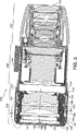
大まかに図面を参照すると、本発明の好ましい実施形態に係る単眼鏡100が示される。好ましい単眼鏡100は、単眼鏡として使用可能であり、または、図1で示される暗視ゴーグル(NVG)の双眼鏡210の一部とすることが可能である。これらの装置は、暗い環境での視界を広くするための周辺光または赤外光を増強するのに使用される。
Referring generally to the drawings, there is shown a monocular 100 according to a preferred embodiment of the present invention. The preferred monocular 100 can be used as a monocular or can be part of the night vision goggles (NVG)
図2を参照すると、単眼鏡100は略管状の形状である。単眼鏡100は、外部環境から光を受信する入力端部102と、ユーザに増強されたイメージを伝達する出力端部104を有する。単眼鏡100の長手方向の断面図である、図3を参照すると、単眼鏡100の主要構成要素は、左から右に、接眼レンズ106、画像増強管190および、対物レンズアセンブリ192であり、これらは全て筐体110内に入れられる。
Referring to FIG. 2, the monocular 100 has a substantially tubular shape. The monocular 100 has an
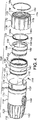
図3〜5を参照すると、接眼レンズ106は、スリーブ130に配置されたレンズセル150を有し、スリーブ130は、スリーブ110に一部分が配置されている。焦点リング170は、筐体110にねじ止めて係合し、筐体110に対して、スリーブ130とレンズセル150を長手方向に平行移動するように作動する。そのような平行移動は、筐体110に対してスリーブ130とレンズセル150を回転することなしに、達成されるのが好ましい。接眼レンズ106は、製造中に視準が合わされる。それゆえ、スリーブ130とレンズセル150は、ユーザによる接眼レンズ106の焦点合わせ中のような作業中、筐体110に対してまたは互いに回転しないことが望ましい。
Referring to FIGS. 3 to 5, the
筐体110は、略管状の本体112である。筐体110の出力端部114は、本体112に形成される、直径方向に間隔の空いた2つの細長いスロット116を有している。スロット116は、図6で示されるショルダーピン118が、本明細書にて後で詳細に説明されるように、偏心スリーブ130に係合するためにその中に挿入されることを可能にする。ショルダーピン118は、スロット116に適合する四角のヘッド118aと、そこから伸びて、スリーブ130に入る、円筒形のシャンク118bを有するのが好ましい。ヘッド118aは、ショルダーピン118の領域の本体112の外形を越えて延びないことが望ましい。ショルダーピン118が望ましいが、当業者は、ショルダーピン118の代わりに、位置決めねじ、または他の既知の固定装置が使用されてもよいことを認識する。
The
図3〜5に戻って参照すると、筐体110はまた、焦点リング170にねじ止めで係合可能な本体112の外側表面に形成される、ねじ山120を有する。入力端部102では、筐体110は、互いに略平行に入力端部102の全長に沿って縦方向に延びる、円周上に間隔の開いた複数の頂部122を有する。頂部122は、使用中にユーザが単眼鏡100を把持するのを助ける。
Referring back to FIGS. 3-5, the
偏心スリーブ130は、図7のページの平面から外側に垂直に延びる外側のシリンダー軸134を有する外側表面132によって形成される略円筒形の本体を含む。内側表面136は、図7のページの平面から外側に垂直に延びる内側のシリンダー軸138を有する。内側のシリンダー軸138は、わずかな距離、すなわち約0.5ミリメートル、外側のシリンダー軸134から、わずかにオフセットされているのが好ましいが、オフセット距離は、0.5ミリメートルでなくてもよいことを当業者は認識することができる。このオフセットは、製造時にスリーブ130が筐体110の中に挿入されて、筐体110内で回転されるときに、内側のシリンダー軸138が外側のシリンダー軸134に対してシフトするように、スリーブ130中に第1の偏心を作る。
The
図8を参照すると、スリーブ130は、また外側表面132の周りで円周上に間隔の空いた一連の凹部140を有する。好ましい実施形態では、40個の凹部140が、均等の間隔で、外側表面132の周りに延びている。凹部140は、必ずしもではないが、外側表面132を通って、内側表面136に延びる。凹部140は、とまりばめで円筒形のシャンク118bを受容して、保持する大きさに作られる。図6で示されるように、スリーブ130が筐体110に挿入されると、スリーブ130は、選択された凹部140の一つが、細長いスロット116と一直線になるように、筐体110と一直線になる。ショルダーピン118は、円筒形のシャンク118bが選択された凹部140に挿入されて、ヘッド118aが、細長いスロット116に収容されるように、細長いスロット116を通して挿入可能である。ショルダーピン118は、筐体110に対して、スリーブ130が回転することを防ぐが、細長いスロット116は、ショルダーピン118とスリーブ130が筐体110に対して、長手方向に平行移動することを可能にする。
Referring to FIG. 8, the
図8に戻って参照すると、外側表面132は、スリーブ130の出力端部の周りを円周上に延びる溝143を有している。溝143は、その中にスナップリングを受容して保持するような大きさに作られる。スナップリングは、図5で見ることができるように、リップ142に対して焦点リング170を固定する。外側表面132はまた、溝143と凹部140の間の外側表面132から半径方向、外側に延びるリップ142を有している。リップ142は、焦点リング170の回転が筐体110に対してスリーブ130を長手方向に平行移動するように、焦点リング170に係合する。
Referring back to FIG. 8, the
外側表面132は、更にスリーブ130の入力端部の周りを円周上に延びる溝141を有している。溝141は、単眼鏡100の組立中に外側表面132と筐体110の間の結合部を密閉するオーリングを受容し保持する大きさに作られる。
The
図8に戻って参照すると、内側表面136はまた、内側表面136から内側のシリンダー軸138に対して延びる入力リップ146の周りに半径方向に延びる複数の歯144を有している。複数の歯144は、この後で詳しく説明されるように、レンズセル150上の複数のかみあい歯と係合する。
Referring back to FIG. 8, the
図5を参照して、内側表面136はまた、固定リング148を受容する内側のねじ147を有する。固定リング148は、スリーブ130に対してレンズセル150を付勢して、焦点を合わせる間に、レンズセル150にスリーブ130の長手方向の動作を伝達する。固定リング148は、内側表面136の内側のねじ147と係合する外側のねじ149を有している。固定リング148の出力端部は、また、固定リング148をスリーブ130に挿入するのに使用される、図4で示される、直径方向に対向する一対のスロット149aを有する。挿入ツール(図示せず)は、スロット149aに係合する。固定リング148を回転して、固定リング148をスリーブ130に通すように、挿入ツールが回転される。
Referring to FIG. 5, the
レンズセル150は、図9のページ面から外に垂直に延びる外側表面152によって形成される略円筒形の本体と、外側表面152から偏心してオフセットされた内側表面156を有する。内側表面156は、図9のページ面から外側に垂直に延びる光軸158を有する。光軸158は、わずかな距離で、外側のシリンダー軸154からわずかにオフセットされる。当業者は、オフセット距離が0.5ミリメートルでなくてもよいことを認識できるが、好ましくは、約0.5ミリメートルである。このオフセットは、製造中に、レンズセル150がスリーブ130に挿入されて、スリーブ130中で回転されるときに、光軸158は外側のシリンダー軸154に対してシフトする。
図3に戻って、レンズセル150は、内側表面156中に配置された複数のレンズ160を有する。レンズ160は、光軸158と全て一直線にされた中央軸162を有する。スリーブ130と第1の偏心で結合するので、光軸158は、光軸158が残りの単眼鏡100と視準が合わさるまで、外側のシリンダー軸134、154の周りで操作可能である。
Returning to FIG. 3, the
図8を参照して、外側表面152は、レンズセル150の入力端部の周りを円周上に延びる溝161を有する。溝161は、単眼鏡100の組み立て中に、外側表面152とスリーブ130間の結合部を密閉するOリングが受容されて保持される大きさに作られる。レンズセル150の入力端部の一部はまた、スリーブ130上の歯144と係合する複数の相手側の歯164を有する。歯164は、レンズセル150の入力端部の周りに円周上に配置される3組で配置されるのが好ましい。しかしながら、当業者は、三組の歯164ではない組数の歯が、レンズセル150の入力端部の周りで間隔を開けて配置されることが出来ることを認識できるであろう。リップ166は、入力端部から長手方向に離れて延びる。リップ166は、複数の切り欠き167を有し、個々の切り欠き167は、一組の歯164に間隔を開けて隣接して配置される。切り欠き167は、製造中に、歯164を切るのを助けるために形成される。
Referring to FIG. 8, the
図4に戻って参照すると、レンズセル150の出力端部は、また、その中に形成される直径方向に対向する一組のスロット168を有する。スロット168は、組立中に、スリーブ130中にレンズセル150を挿入するのを助ける挿入ツール(図示せず)を受容する大きさに作られる。溝169は、溝161とスロット168間の外側表面152に形成される。溝169は、単眼鏡100の組み立て中、外側表面152とスリーブ130間の結合部を密閉するОリングを受容して保持する大きさに作られる。
Referring back to FIG. 4, the output end of the
焦点リング170は、外側表面172と内側表面174によって形成される略環状の本体を有する。外側表面172は、円周上に間隔の空いた複数の溝176を有する。溝176は、使用中に、ユーザに焦点リング170を把持して、接眼レンズ106の焦点を合わすために焦点リング170を回転することを可能にする。
The
内側表面174は、筐体110上の外側のねじ120と係合する、ねじが切られた構成178を有する。内側表面174はまた、内側表面174とスリーブ130間の結合部を密閉するためのОリングを受容して保持する大きさに作られる。更に図5を参照すると、内側表面174は、スリーブ130に対して延びて、スリーブ130のリップ142に係合するリップ182を有する。
The
スナップリング184は、スリーブ130に対して焦点リング170を固定するのに使用される。スナップリング184は、スリーブ130の溝143にはめ込まれて、スリーブ130のリップ142に対して焦点リング170のリップ182を固定する。
The
図3に戻って参照すると、画像増強装置190は、筐体110に配置されて、全ての光学素子、電子機器、画像増強装置190を操作するのに関連した装置を有する。対物レンズアセンブリ192は、画像増強装置190と入力端部102間の筐体110に配置される。画像増強装置190と対物レンズアセンブリ192は、詳細に説明する必要はないいかなる既存の装置とすることが可能である。しかしながら、図3は、対物レンズアセンブリ192を有する複数のレンズを示すが、当業者は、対物レンズアセンブリ192は、単一のレンズだけを有することも可能であることを認識できるであろう。電源コネクタ194は、筐体本体112から外側に延びる。電源コネクタ194は、画像増強装置190を電源(図示せず)に電気的に接続する。電源コネクタ194はまた、双眼鏡または兵器の照準器のように、単眼鏡100を支持部材に取り外し可能に物理的に接続する。
Referring back to FIG. 3, the
単眼鏡100の内側の構造に湿気や泥が入ることからまもるために、上述した構成要素のいくつかの係合面を密閉するのに、複数のOリング196が単眼鏡100で使用される。
A plurality of O-
接眼レンズ106を組み立てるために、画像増強管190と対物レンズアセンブリ192は、既存の方法に従って単眼鏡100に挿入される。レンズセル150は、レンズセル150のはめあい歯164がスリーブ130の歯144に係合するように、図8で示されるようにスリーブ130に一部分が挿入される。結合されたスリーブ130とレンズセル150は、その後、筐体セル110に挿入される。スリーブ130とレンズセル150は、単眼鏡100と視準が合うために、互いに対してそして筐体110に対して、独立して回転される。スリーブ130の内側のシリンダー軸138に対する、外側のシリンダー軸134の偏心と同様に、レンズセル150の外側のシリンダー軸154に対する光軸158の偏心は、光軸158が画像増強装置190と対物レンズアセンブリ192と視準が合うまで、筐体110に対してスリーブ130とレンズセル150が回転することを可能にする。歯144とはめあい歯164は、視準を合わせる間、調整可能なように傾斜している。歯164、144が完全な視準を保持するように完全に一直線でない場合には、レンズセル150は、接眼レンズ106の視準をわずかにずらすが、歯164、144間のはめあい係合を維持するように、スリーブ130に対して、調整可能である。
To assemble the
次にスリーブ130は、選択された凹部140が個々の細長いスロット116に一直線になるように、筐体110と一直線にされる。凹部140がスロット116の一つと一直線にされるときは、別の凹部140は、残りのスロット116と一直線になる。ショルダーピン118は、円筒型のシャンク118bが選択された凹部140に挿入されて、ヘッド118aがスロット116に挿入されるように、個々のスロット116を介して挿入される。ショルダーピン118がスロット116の全長を平行移動することに制限されるので、ショルダーピン118は、筐体110に対するスリーブ130とレンズセル150の回転を防いで、更に、筐体110に対するスリーブ130の長手方向の平行移動を制限する。凹部140とスロット116が完全な視準を保持するように完全に一直線でない場合には、接眼レンズ106の視準をほんのわずかにずらすが、凹部140とスロット116間の一直線を保持するために、スリーブ130は、筐体に対して調整可能である。一度光軸158の視準が合わされると、固定リング148はスリーブ130に対してレンズセル150を固定するように、スリーブ130上でねじ止めされる。
The
焦点リング170が次に筐体110上でねじ止めされる。スナップリング184は溝143にはめ込まれて、焦点リング170のリップ182をスリーブ130のリップ142に対して固定する、そして、焦点リング170と筐体110のねじ止め結合によって、生じる焦点リング170の平行移動は、スリーブ130またはレンズセル150を回転することなしに、スリーブ130とレンズセル150に伝達される。
The
単眼鏡100は、ヘルメットに取り付けられた、または携帯用の暗視システムである。あるいは、単眼鏡100は、例えば、ライフルまたは戦車の兵器システムの照準器として使用されることも可能である。更に単眼鏡100は、焦点合わせおよび視準合わせが必要な、いかなる光学系に組み込むことが可能である。 The monocular 100 is a night vision system attached to a helmet or portable. Alternatively, the monocular 100 can be used, for example, as a sight for a rifle or tank weapon system. Furthermore, the monocular 100 can be incorporated into any optical system that requires focusing and collimation.
図1に戻って参照すると、第2の単眼鏡200は、双眼鏡210を形成するために、単眼鏡100とともに使用される。第2の単眼鏡200は、単眼鏡100と構造的に類似しているのが好ましい。第1および第2の単眼鏡100、200は、単眼鏡100、200それぞれの電源コネクタ194を介して双眼鏡フレーム212に取り外し可能に接続される。単眼鏡100、200の一つが修理され、または交換される必要がある場合には、単眼鏡は、フレーム212から取り外されて修理され、または交換される。修理されたまたは交換用の単眼鏡が双眼鏡フレーム212に接続されるときには、修理された、または交換された単眼鏡は、元の単眼鏡と視準を合わせる必要がない。
Referring back to FIG. 1, the
本発明は、特定の実施形態を参照しながら本明細書で説明されるが、本発明は、詳細に示された内容に制限されることを意図しない。それどころか、本発明から逸脱しないで請求の範囲に均等な範囲で、詳細に様々な修正をすることが可能である。本発明の好ましい実施形態が本明細書で示されて説明されるが、そのような実施形態は、単に例として提供されることが理解される。当業者は、本発明の精神を逸脱しない範囲で多くの変形、変更および置換を思いつく。従って、添付の請求の範囲は、本発明の精神と範囲に含まれるような変形全てをカバーすることを意図している。 Although the invention is described herein with reference to specific embodiments, the invention is not intended to be limited to the details shown. On the contrary, various modifications can be made in detail without departing from the present invention and within the scope equivalent to the claims. While preferred embodiments of the invention are shown and described herein, it is understood that such embodiments are provided merely as examples. Those skilled in the art will envision many modifications, changes and substitutions without departing from the spirit of the invention. Accordingly, the appended claims are intended to cover all such modifications as fall within the spirit and scope of the invention.
本発明の好ましい実施形態の「発明を実施するための最良の形態」と同様に「発明の開示」も、本明細に組みこまれ、本明細書の一部を構成する添付図面と併せて読むことにより更に理解される。本発明を説明する目的のために、現在好ましい実施形態が図面で示される。しかしながら本発明は示される正確なアレンジメントと装置に制限されない。図面では、同じ参照番号が、複数の図面を通して同じ要素を表すのに、使用される。 “Disclosure of the Invention” as well as “Best Mode for Carrying Out the Invention” of a preferred embodiment of the present invention are incorporated in the present specification and read in conjunction with the accompanying drawings constituting a part of the present specification. Is further understood. For the purpose of illustrating the invention, there are shown in the drawings embodiments which are presently preferred. However, the invention is not limited to the exact arrangement and apparatus shown. In the drawings, the same reference numerals are used to represent the same elements throughout the drawings.
Claims (17)
略円筒形のスリーブ本体を有するスリーブであって、前記スリーブ本体が、第1の長手方向の軸線を有する外側表面と、前記第1の長手方向の軸線から偏心してオフセットされる第2の長手方向の軸線を有する内側表面とを有する、前記レンズセルが挿入されるスリーブと、
略円筒型の本体を有する筐体であって、前記スリーブが、少なくとも一部分挿入される筐体と、
を有する、光学系であって、
前記レンズセルの光軸が所望の位置と一直線になるように、前記レンズセルと前記スリーブは互いに対してそして前記筐体に対して回転されて、前記レンズセルの光軸が、前記所望の位置と一直線にされた後に、前記レンズセルが前記スリーブに取り外し可能に固定して接続され、前記スリーブが前記筐体に対して前記スリーブの回転を防ぐように前記筐体に取り外し可能に接続され、
前記レンズセルの光軸が所望の位置と一直線になって、前記レンズセルが前記スリーブに対して固定され、前記スリーブが前記筐体に対して固定されると、前記筐体に対して前記レンズセルの光軸が固定され、
前記レンズセルの前記スリーブに対する固定を解除し、前記スリーブの前記筐体に対する固定を解除すると、再度、前記レンズセルの光軸を所望の位置に調節することができ、
前記スリーブが前記筐体に対して前記スリーブの回転を防ぐように接続された後は、前記スリーブが、前記筐体に対して長手方向に平行移動可能である、
光学系。An approximately cylindrical lens cell body and a lens cell having an optical lens system therein, wherein the lens cell body is offset from the central longitudinal axis of the lens cell and the central longitudinal axis of the lens cell. A lens cell having an optical axis of the lens cell to be
A sleeve having a generally cylindrical sleeve body, wherein the sleeve body has an outer surface having a first longitudinal axis and a second longitudinal direction offset eccentrically from the first longitudinal axis. A sleeve into which the lens cell is inserted, and an inner surface having an axis of
A housing having a substantially cylindrical body, wherein the sleeve is inserted at least partially;
An optical system comprising:
The lens cell and the sleeve are rotated relative to each other and relative to the housing so that the optical axis of the lens cell is aligned with the desired position, so that the optical axis of the lens cell is the desired position. And the lens cell is removably fixedly connected to the sleeve, and the sleeve is removably connected to the housing to prevent rotation of the sleeve with respect to the housing,
When the optical axis of the lens cell is aligned with a desired position, the lens cell is fixed to the sleeve, and the sleeve is fixed to the casing, the lens is fixed to the casing. The optical axis of the cell is fixed,
Unpinned to said sleeve of said lens cell and releases the fixing to said housing of said sleeve, again, Ki the optical axis of said lens cell de be adjusted to a desired position,
After the sleeve is connected to the housing to prevent rotation of the sleeve, the sleeve is translatable in the longitudinal direction with respect to the housing.
Optical system.
レンズアセンブリと、
前記レンズアセンブリと接眼レンズとの間に配置される画像増強装置と、
を有する、単眼鏡。An optical system according to claim 1;
A lens assembly;
An image intensifier device disposed between the lens assembly and the eyepiece;
Having monoculars.
第1の単眼鏡であって、前記第1の単眼鏡が、
略円筒形のレンズセル本体とその中に光学レンズ系を有するレンズセルであって、前記レンズセル本体が、レンズセルの中央長手方向の軸線と前記レンズセルの中央長手方向の軸線から偏心してオフセットされるレンズセルの光軸とを有する、レンズセルと、
略円筒形のスリーブ本体を有するスリーブであって、前記スリーブ本体が、第1の長手方向の軸線を有する外側表面と、前記第1の長手方向の軸線から偏心してオフセットされる第2の長手方向の軸線を有する内側表面とを有し、前記レンズセルが挿入される、スリーブと、
略円筒型の本体を有する筐体であって、前記スリーブが、少なくとも一部分挿入される筐体と、
を有し、
前記レンズセルの光軸が所望の位置と一直線になるように、前記レンズセルと前記スリーブは互いに対してそして前記筐体に対して回転されて、前記レンズセルの光軸が、前記所望の位置と一直線にされた後に、前記レンズセルが前記スリーブに取り外し可能に固定して接続され、前記スリーブが前記筐体に対して前記スリーブの回転を防ぐように前記筐体に取り外し可能に接続される、
第1の単眼鏡と、
前記第1の単眼鏡と同じ構成を有する、第2の単眼鏡と、を有し、
前記第1と前記第2の単眼鏡がそれぞれ前記フレームに取り外し可能に接続され、
前記レンズセルの光軸が所望の位置と一直線になって、前記レンズセルが前記スリーブに対して固定され、前記スリーブが前記筐体に対して固定されると、前記筐体に対して前記レンズセルの光軸が固定され、
前記レンズセルの前記スリーブに対する固定を解除し、前記スリーブの前記筐体に対する固定を解除すると、再度、前記レンズセルの光軸を所望の位置に調節することができ、
前記スリーブが前記筐体に対して前記スリーブの回転を防ぐように接続された後は、前記スリーブが、前記筐体に対して長手方向に平行移動可能である、
双眼鏡。Frame,
First monoculars, wherein the first monoculars are
An approximately cylindrical lens cell body and a lens cell having an optical lens system therein, wherein the lens cell body is offset from the central longitudinal axis of the lens cell and the central longitudinal axis of the lens cell. A lens cell having an optical axis of the lens cell to be
A sleeve having a generally cylindrical sleeve body, wherein the sleeve body has an outer surface having a first longitudinal axis and a second longitudinal direction offset eccentrically from the first longitudinal axis. An inner surface having an axis of the sleeve, into which the lens cell is inserted,
A housing having a substantially cylindrical body, wherein the sleeve is inserted at least partially;
Have
The lens cell and the sleeve are rotated relative to each other and relative to the housing so that the optical axis of the lens cell is aligned with the desired position, so that the optical axis of the lens cell is the desired position. The lens cell is removably fixedly connected to the sleeve and the sleeve is removably connected to the housing to prevent rotation of the sleeve relative to the housing. ,
A first monocular;
A second monocular having the same configuration as the first monocular,
The first and second monoculars are each removably connected to the frame;
When the optical axis of the lens cell is aligned with a desired position, the lens cell is fixed to the sleeve, and the sleeve is fixed to the casing, the lens is fixed to the casing. The optical axis of the cell is fixed,
Unpinned to said sleeve of said lens cell and releases the fixing to said housing of said sleeve, again, Ki the optical axis of said lens cell de be adjusted to a desired position,
After the sleeve is connected to the housing to prevent rotation of the sleeve, the sleeve is translatable in the longitudinal direction with respect to the housing.
binoculars.
略円筒形のレンズセル本体を有するレンズセルを備える段階であって、前記レンズセル本体は、レンズセルの中央長手方向軸と、前記レンズセルの中央長手方向軸からオフセットされたレンズセルの光軸と、を有する、段階と、
前記レンズセルをスリーブに挿入する段階であって、前記スリーブは、略円筒形のスリーブ本体を有し、前記スリーブ本体は、第1の長手方向軸線を有する外側表面と、前記第1の長手方向軸線からオフセットされた第2の長手方向軸線を有する内側表面と、を有する段階と、
前記スリーブを筐体に少なくとも一部分挿入する段階であって、前記筐体は、略円筒形の筐体本体を有する段階と、
前記スリーブを独立して回転し、前記レンズセルを、該レンズセルの光軸が所望の位置にあるまで、前記筐体に対して独立して回転する段階と、
前記レンズセルに対する前記スリーブの回転を防ぐために、前記スリーブと前記レンズセルが互いに対して取り外し可能に固定する段階と、
前記筐体に対して前記スリーブの回転を防ぐために、前記スリーブを前記筐体に取り外し可能に固定する段階と、
を有し、
前記レンズセルの光軸が所望の位置と一直線になって、前記レンズセルが前記スリーブに対して固定され、前記スリーブが前記筐体に対して固定されると、前記筐体に対して前記レンズセルの光軸が固定され、
前記レンズセルの前記スリーブに対する固定を解除し、前記スリーブの前記筐体に対する固定を解除すると、再度、前記レンズセルの光軸を所望の位置に調節することができ、
前記スリーブを前記筐体に固定する段階は、前記筐体に対して前記スリーブを長手方向に平行移動することを可能にする、
視準のあった光学装置を製造する方法。A method of manufacturing a collimating optical device, the method comprising:
A lens cell having a generally cylindrical lens cell body, the lens cell body having a central longitudinal axis of the lens cell and an optical axis of the lens cell offset from the central longitudinal axis of the lens cell; And having a stage;
Inserting the lens cell into a sleeve, the sleeve having a generally cylindrical sleeve body, the sleeve body having an outer surface having a first longitudinal axis; and the first longitudinal direction. An inner surface having a second longitudinal axis offset from the axis; and
Inserting at least a portion of the sleeve into the housing, the housing having a substantially cylindrical housing body;
Rotating the sleeve independently and rotating the lens cell independently with respect to the housing until the optical axis of the lens cell is in a desired position;
Removably securing the sleeve and the lens cell relative to each other to prevent rotation of the sleeve relative to the lens cell;
Removably securing the sleeve to the housing to prevent rotation of the sleeve relative to the housing;
Have
When the optical axis of the lens cell is aligned with a desired position, the lens cell is fixed to the sleeve, and the sleeve is fixed to the casing, the lens is fixed to the casing. The optical axis of the cell is fixed,
Unpinned to said sleeve of said lens cell and releases the fixing to said housing of said sleeve, again, Ki the optical axis of said lens cell de be adjusted to a desired position,
Securing the sleeve to the housing allows the sleeve to translate longitudinally relative to the housing;
A method for manufacturing a collimated optical device.
Applications Claiming Priority (3)
| Application Number | Priority Date | Filing Date | Title |
|---|---|---|---|
| US11/268,784 | 2005-11-08 | ||
| US11/268,784 US7397617B2 (en) | 2005-11-08 | 2005-11-08 | Collimated optical system |
| PCT/US2006/043373 WO2007056385A1 (en) | 2005-11-08 | 2006-11-07 | Collimated optical system |
Publications (3)
| Publication Number | Publication Date |
|---|---|
| JP2009515220A JP2009515220A (en) | 2009-04-09 |
| JP2009515220A5 JP2009515220A5 (en) | 2009-12-24 |
| JP5166274B2 true JP5166274B2 (en) | 2013-03-21 |
Family
ID=37847122
Family Applications (1)
| Application Number | Title | Priority Date | Filing Date |
|---|---|---|---|
| JP2008539123A Expired - Fee Related JP5166274B2 (en) | 2005-11-08 | 2006-11-07 | Parallel optical system |
Country Status (7)
| Country | Link |
|---|---|
| US (2) | US7397617B2 (en) |
| EP (1) | EP1949163A1 (en) |
| JP (1) | JP5166274B2 (en) |
| CA (1) | CA2623827C (en) |
| IL (1) | IL190238A (en) |
| TW (1) | TWI426312B (en) |
| WO (1) | WO2007056385A1 (en) |
Families Citing this family (13)
| Publication number | Priority date | Publication date | Assignee | Title |
|---|---|---|---|---|
| US7397617B2 (en) | 2005-11-08 | 2008-07-08 | Itt Manufacturing Enterprises, Inc. | Collimated optical system |
| US7652832B2 (en) | 2007-11-30 | 2010-01-26 | Itt Manufacturing Enterprises, Inc. | Collimated optical system with clip ring eccentric locking mechanism |
| US8120845B2 (en) | 2008-12-15 | 2012-02-21 | Itt Manufacturing Enterprises, Inc. | Collimated intensified vision system and method of collimating |
| DE102010016761A1 (en) * | 2010-05-03 | 2011-11-03 | Schmidt & Bender Gmbh & Co. Kg | Connecting device for two optical devices |
| DE102010016785A1 (en) | 2010-05-04 | 2011-11-10 | Schmidt & Bender Gmbh & Co. Kg | Optical system with a connection bridge |
| US8507839B2 (en) | 2010-09-22 | 2013-08-13 | Exelis, Inc. | Image intensifier tube with a mounting surface |
| US8313608B2 (en) | 2010-09-22 | 2012-11-20 | Exelis, Inc. | Method of aligning an imaging device in an optical system |
| CN103064179B (en) * | 2013-01-30 | 2015-07-01 | 武汉高明兰光电科技有限公司 | Telescopic sighting telescope hood |
| US20140226213A1 (en) * | 2013-02-13 | 2014-08-14 | Exelis, Inc. | Removable display for optical device |
| US9335506B2 (en) * | 2013-03-05 | 2016-05-10 | Exelis, Inc. | Translational optic alignment locking device |
| TWI494632B (en) * | 2013-05-17 | 2015-08-01 | Omnivision Tech Inc | Projector and optical component adjustment system thereof |
| US9791320B2 (en) * | 2015-09-11 | 2017-10-17 | Burle Technologies, Llc | Mounting system and method for night vision tubes |
| USD834133S1 (en) | 2017-06-07 | 2018-11-20 | Steiner Eoptics, Inc. | Dual beam aiming laser |
Family Cites Families (24)
| Publication number | Priority date | Publication date | Assignee | Title |
|---|---|---|---|---|
| US2424011A (en) | 1945-04-11 | 1947-07-15 | Levallois Optique Et Prec | Telescope adjusting device |
| GB809246A (en) | 1954-07-22 | 1959-02-18 | Aviamac Ltd | Improvements in or relating to devices for effecting adjustments in two dimensions |
| US3713725A (en) | 1969-11-24 | 1973-01-30 | Minolta Camera Kk | Camera objective lens adjustment member |
| US3737667A (en) | 1971-08-18 | 1973-06-05 | B Babb | Electro-optical viewing device |
| JPS56167321U (en) * | 1980-05-16 | 1981-12-11 | ||
| US4669833A (en) | 1985-01-25 | 1987-06-02 | Simmons Outdoor Corporation | Spotting scope with alignment viewer |
| US4723075A (en) | 1985-06-12 | 1988-02-02 | The United States Of America As Represented By The Secretary Of The Air Force | Translational mount for large optical elements |
| US4743763A (en) | 1986-09-26 | 1988-05-10 | The United States Of America As Repesented By The United States Department Of Energy | Article mounting and position adjustment stage |
| US5084780A (en) * | 1989-09-12 | 1992-01-28 | Itt Corporation | Telescopic sight for day/night viewing |
| US5223974A (en) | 1991-12-20 | 1993-06-29 | Itt Corporation | Collimator for binocular viewing system |
| JPH0792395A (en) * | 1993-09-21 | 1995-04-07 | Nec Corp | Goggle type noctovision device |
| JPH0821939A (en) * | 1994-07-06 | 1996-01-23 | Asahi Optical Co Ltd | Device for adjusting lens position in optical axis direction |
| US5604630A (en) | 1995-06-30 | 1997-02-18 | Itt Corporation | Night vision monocular with balanced optics |
| JP3515683B2 (en) * | 1996-09-13 | 2004-04-05 | ペンタックス株式会社 | binoculars |
| US6456497B1 (en) | 1998-03-12 | 2002-09-24 | Itt Manufacturing Enterprises, Inc. | Night vision binoculars |
| US6310721B2 (en) | 1998-12-11 | 2001-10-30 | International Technologies (Lasers) Ltd. | Night vision monocular |
| US6262853B1 (en) * | 1998-12-25 | 2001-07-17 | Olympus Optical Co., Ltd. | Lens barrel having deformable member |
| US6259088B1 (en) | 1999-06-24 | 2001-07-10 | The United States Of America As Represented By The Secretary Of The Army | Image intensifier tube with curved components |
| US6687053B1 (en) | 2001-09-27 | 2004-02-03 | Itt Manufacturing Enterprises, Inc. | Binocular device and method utilizing monocular devices |
| JP3867894B2 (en) * | 2001-11-08 | 2007-01-17 | 株式会社リコー | Alignment device |
| JP3650605B2 (en) * | 2002-01-28 | 2005-05-25 | ペンタックス株式会社 | Lens holding device |
| US6924931B1 (en) * | 2003-02-26 | 2005-08-02 | Itt Manufacturing Enterprises, Inc. | Line of sight adjustment for night vision binoculars |
| DE502004003121D1 (en) | 2003-12-12 | 2007-04-19 | Leica Camera Ag | Binocular binoculars with integrated laser rangefinder |
| US7397617B2 (en) | 2005-11-08 | 2008-07-08 | Itt Manufacturing Enterprises, Inc. | Collimated optical system |
-
2005
- 2005-11-08 US US11/268,784 patent/US7397617B2/en active Active
-
2006
- 2006-11-07 EP EP06844280A patent/EP1949163A1/en not_active Withdrawn
- 2006-11-07 JP JP2008539123A patent/JP5166274B2/en not_active Expired - Fee Related
- 2006-11-07 WO PCT/US2006/043373 patent/WO2007056385A1/en active Application Filing
- 2006-11-07 CA CA2623827A patent/CA2623827C/en active Active
- 2006-11-07 TW TW095141117A patent/TWI426312B/en not_active IP Right Cessation
-
2007
- 2007-08-01 US US11/888,590 patent/US7365905B2/en active Active
-
2008
- 2008-03-17 IL IL190238A patent/IL190238A/en active IP Right Grant
Also Published As
| Publication number | Publication date |
|---|---|
| US7397617B2 (en) | 2008-07-08 |
| IL190238A0 (en) | 2008-11-03 |
| TWI426312B (en) | 2014-02-11 |
| CA2623827C (en) | 2014-04-08 |
| JP2009515220A (en) | 2009-04-09 |
| IL190238A (en) | 2011-09-27 |
| TW200734712A (en) | 2007-09-16 |
| EP1949163A1 (en) | 2008-07-30 |
| WO2007056385A1 (en) | 2007-05-18 |
| US20070103796A1 (en) | 2007-05-10 |
| US20070279769A1 (en) | 2007-12-06 |
| US7365905B2 (en) | 2008-04-29 |
| CA2623827A1 (en) | 2007-05-18 |
Similar Documents
| Publication | Publication Date | Title |
|---|---|---|
| JP5166274B2 (en) | Parallel optical system | |
| RU2664163C2 (en) | Video endoscopic device | |
| US7652832B2 (en) | Collimated optical system with clip ring eccentric locking mechanism | |
| US7944611B1 (en) | High zoom ratio optical sighting device | |
| US11375087B1 (en) | Camera systems for scopes | |
| US5527263A (en) | Stereo endoscope | |
| JP2009515220A5 (en) | ||
| US6346076B1 (en) | Endoscope | |
| DE69931127D1 (en) | Night vision monocular | |
| JP5596701B2 (en) | Visual system with enhanced collimation and collimation method | |
| US20100264310A1 (en) | Ganged focus mechanism for an optical device | |
| JP4796864B2 (en) | Shading device | |
| CN105158896B (en) | Endoscope replaces head | |
| US4655569A (en) | Optical eyepiece adaptor for cameras | |
| JP2017196283A (en) | Inspection apparatus | |
| KR101605866B1 (en) | Binoculars night vision goggle | |
| JPH11352416A (en) | Tip structure of stereoscopic endoscope | |
| JP2017102147A (en) | Variable magnification optical unit and telescope system |
Legal Events
| Date | Code | Title | Description |
|---|---|---|---|
| A521 | Request for written amendment filed |
Free format text: JAPANESE INTERMEDIATE CODE: A523 Effective date: 20091106 |
|
| A621 | Written request for application examination |
Free format text: JAPANESE INTERMEDIATE CODE: A621 Effective date: 20091106 |
|
| A977 | Report on retrieval |
Free format text: JAPANESE INTERMEDIATE CODE: A971007 Effective date: 20110804 |
|
| A131 | Notification of reasons for refusal |
Free format text: JAPANESE INTERMEDIATE CODE: A131 Effective date: 20110809 |
|
| A521 | Request for written amendment filed |
Free format text: JAPANESE INTERMEDIATE CODE: A523 Effective date: 20111104 |
|
| A131 | Notification of reasons for refusal |
Free format text: JAPANESE INTERMEDIATE CODE: A131 Effective date: 20120306 |
|
| A521 | Request for written amendment filed |
Free format text: JAPANESE INTERMEDIATE CODE: A523 Effective date: 20120511 |
|
| A711 | Notification of change in applicant |
Free format text: JAPANESE INTERMEDIATE CODE: A711 Effective date: 20120815 |
|
| TRDD | Decision of grant or rejection written | ||
| A01 | Written decision to grant a patent or to grant a registration (utility model) |
Free format text: JAPANESE INTERMEDIATE CODE: A01 Effective date: 20121120 |
|
| A61 | First payment of annual fees (during grant procedure) |
Free format text: JAPANESE INTERMEDIATE CODE: A61 Effective date: 20121220 |
|
| FPAY | Renewal fee payment (event date is renewal date of database) |
Free format text: PAYMENT UNTIL: 20151228 Year of fee payment: 3 |
|
| R150 | Certificate of patent or registration of utility model |
Free format text: JAPANESE INTERMEDIATE CODE: R150 |
|
| LAPS | Cancellation because of no payment of annual fees |