JP5164905B2 - Image forming apparatus - Google Patents
Image forming apparatus Download PDFInfo
- Publication number
- JP5164905B2 JP5164905B2 JP2009086514A JP2009086514A JP5164905B2 JP 5164905 B2 JP5164905 B2 JP 5164905B2 JP 2009086514 A JP2009086514 A JP 2009086514A JP 2009086514 A JP2009086514 A JP 2009086514A JP 5164905 B2 JP5164905 B2 JP 5164905B2
- Authority
- JP
- Japan
- Prior art keywords
- toner
- image
- color
- image forming
- patch
- Prior art date
- Legal status (The legal status is an assumption and is not a legal conclusion. Google has not performed a legal analysis and makes no representation as to the accuracy of the status listed.)
- Expired - Fee Related
Links
Images


Classifications
-
- G—PHYSICS
- G03—PHOTOGRAPHY; CINEMATOGRAPHY; ANALOGOUS TECHNIQUES USING WAVES OTHER THAN OPTICAL WAVES; ELECTROGRAPHY; HOLOGRAPHY
- G03G—ELECTROGRAPHY; ELECTROPHOTOGRAPHY; MAGNETOGRAPHY
- G03G15/00—Apparatus for electrographic processes using a charge pattern
- G03G15/01—Apparatus for electrographic processes using a charge pattern for producing multicoloured copies
- G03G15/0105—Details of unit
- G03G15/0131—Details of unit for transferring a pattern to a second base
-
- G—PHYSICS
- G03—PHOTOGRAPHY; CINEMATOGRAPHY; ANALOGOUS TECHNIQUES USING WAVES OTHER THAN OPTICAL WAVES; ELECTROGRAPHY; HOLOGRAPHY
- G03G—ELECTROGRAPHY; ELECTROPHOTOGRAPHY; MAGNETOGRAPHY
- G03G15/00—Apparatus for electrographic processes using a charge pattern
- G03G15/50—Machine control of apparatus for electrographic processes using a charge pattern, e.g. regulating differents parts of the machine, multimode copiers, microprocessor control
-
- G—PHYSICS
- G03—PHOTOGRAPHY; CINEMATOGRAPHY; ANALOGOUS TECHNIQUES USING WAVES OTHER THAN OPTICAL WAVES; ELECTROGRAPHY; HOLOGRAPHY
- G03G—ELECTROGRAPHY; ELECTROPHOTOGRAPHY; MAGNETOGRAPHY
- G03G2215/00—Apparatus for electrophotographic processes
- G03G2215/01—Apparatus for electrophotographic processes for producing multicoloured copies
- G03G2215/0103—Plural electrographic recording members
- G03G2215/0119—Linear arrangement adjacent plural transfer points
- G03G2215/0122—Linear arrangement adjacent plural transfer points primary transfer to an intermediate transfer belt
- G03G2215/0125—Linear arrangement adjacent plural transfer points primary transfer to an intermediate transfer belt the linear arrangement being horizontal or slanted
- G03G2215/0129—Linear arrangement adjacent plural transfer points primary transfer to an intermediate transfer belt the linear arrangement being horizontal or slanted horizontal medium transport path at the secondary transfer
-
- G—PHYSICS
- G03—PHOTOGRAPHY; CINEMATOGRAPHY; ANALOGOUS TECHNIQUES USING WAVES OTHER THAN OPTICAL WAVES; ELECTROGRAPHY; HOLOGRAPHY
- G03G—ELECTROGRAPHY; ELECTROPHOTOGRAPHY; MAGNETOGRAPHY
- G03G2215/00—Apparatus for electrophotographic processes
- G03G2215/01—Apparatus for electrophotographic processes for producing multicoloured copies
- G03G2215/0151—Apparatus for electrophotographic processes for producing multicoloured copies characterised by the technical problem
- G03G2215/0164—Uniformity control of the toner density at separate colour transfers
Landscapes
- Physics & Mathematics (AREA)
- General Physics & Mathematics (AREA)
- Engineering & Computer Science (AREA)
- Microelectronics & Electronic Packaging (AREA)
- Color Electrophotography (AREA)
- Control Or Security For Electrophotography (AREA)
Description
本発明は、複数色のトナー像を中間転写体等に転写して重ね合わせる画像形成装置、詳しくは、カラー調整に用いる複数色のトナー像を重なり状態で検出して個別のトナー載り量を求める演算処理に関する。 The present invention relates to an image forming apparatus that transfers and superimposes a plurality of color toner images onto an intermediate transfer member or the like, and more specifically, detects a plurality of color toner images used for color adjustment in an overlapped state to obtain individual toner loadings. It relates to arithmetic processing.
像担持体に形成した複数色のトナー像を画像搬送体(中間転写体又は記録材搬送体)に転写して重ね合わせることによりフルカラー画像を形成する画像形成装置が広く用いられている。フルカラー画像形成装置は、複数色の現像を行う1個の像担持体を用いる方式と、複数の像担持体から各色別のトナー像を転写して重ね合わせる方式とを含む。 2. Description of the Related Art Image forming apparatuses that form full-color images by transferring and superimposing a plurality of color toner images formed on an image carrier onto an image carrier (intermediate transfer member or recording material carrier) are widely used. The full-color image forming apparatus includes a method using one image carrier for developing a plurality of colors and a method for transferring and superimposing toner images for each color from the plurality of image carriers.
フルカラー画像形成装置は、複数色のトナー像におけるトナー載り量の比率が変化すると中間色(二次色)の色調が変化して画像品質が低下する。そのため、各色別のテスト画像(パッチトナー像)を形成して濃度又は色調を測定するテスト画像測定モードが所定のタイミングで実行される。テスト画像測定モードでは、所定条件で各色のテスト画像(トナー像)が形成され、テスト画像の濃度測定結果を各色のトナー像形成条件にフィードバックして出力画像のカラーバランスを適正化する。 In the full-color image forming apparatus, when the ratio of the toner application amount in the toner images of a plurality of colors changes, the color tone of the intermediate color (secondary color) changes and the image quality deteriorates. Therefore, a test image measurement mode in which a test image (patch toner image) for each color is formed and the density or color tone is measured is executed at a predetermined timing. In the test image measurement mode, a test image (toner image) of each color is formed under a predetermined condition, and the density measurement result of the test image is fed back to the toner image formation condition of each color to optimize the color balance of the output image.
特許文献1に示されるテスト画像測定モードは、各色のテスト画像を中間転写体上で重ね合わせて記録材に転写して定着し、定着された記録材上のテスト画像をカラーセンサで測定する。このため、テスト画像測定モードを実行するごとに、記録材が消費されて不必要な画像が出力されてしまう。
In the test image measurement mode disclosed in
そこで、中間転写体上で各色のテスト画像のトナー載り量を測定して、記録材を消費することなくテスト画像測定モードを実行することが提案されている。 Therefore, it has been proposed to measure the amount of applied toner of each color test image on the intermediate transfer member and execute the test image measurement mode without consuming the recording material.
特許文献2に示されるテスト画像測定モードは、各色のテスト画像(パッチトナー像)が、中間転写体の別々の位置に転写され、中間転写体上で各色のテスト画像が個別にトナー載り量を測定される。中間転写体に転写された各色のテスト画像に対して、光学センサが順番に赤外線の照明光を照射して、正反射光の光量を個別に測定している。
In the test image measurement mode disclosed in
特許文献3には、レーザ光を照射して照射面を三角測距するレーザ変位センサを用いてトナー高さを測定する画像形成装置が示される。ここでも、各色のテスト画像は、別々に高さを測定されてトナー載り量に換算される。 Patent Document 3 discloses an image forming apparatus that measures a toner height using a laser displacement sensor that irradiates a laser beam and triangulates the irradiated surface. Again, the height of each color test image is measured separately and converted to the amount of applied toner.
特許文献2に示される制御では、イエロー、マゼンタ、シアン、ブラックのテスト画像を一列に並べて形成するため、通常の画像と画像の間隔(いわゆる紙間)には収まらない。
In the control disclosed in
ここで、画像と画像の間隔を拡大すれば、4色のテスト画像を一列に並べて形成できるが、画像と画像の間隔を拡大すると画像形成装置の生産性が低下する。複数の間隔に分けて4色のテスト画像を形成した場合、テスト画像測定モードの実行頻度が低下する。光学センサを複数配置して、複数色のテスト画像を並列に検出する場合、光学センサの設置コストが増すとともに、光学センサ間の特性のばらつきがカラー調整の誤差となる。 Here, if the interval between the images is increased, four color test images can be formed in a line, but if the interval between the images is increased, the productivity of the image forming apparatus decreases. When test images of four colors are formed at a plurality of intervals, the execution frequency of the test image measurement mode decreases. When a plurality of optical sensors are arranged and test images of a plurality of colors are detected in parallel, the installation cost of the optical sensors increases, and variation in characteristics between the optical sensors becomes an error in color adjustment.
本発明は、記録材を消費することも、画像と画像の間隔を拡大することもなく、テスト画像測定モードを実行してトナー像形成条件を制御できる画像形成装置を提供することを目的としている。 SUMMARY OF THE INVENTION An object of the present invention is to provide an image forming apparatus capable of controlling a toner image forming condition by executing a test image measurement mode without consuming a recording material or increasing an interval between images. .
本発明の画像形成装置は、スクリーン角度とスクリーン線数のうち少なくとも一方が異なるように第1の色のトナー像と第2の色のトナー像を画像搬送体に重ねて形成するトナー像形成手段と、前記トナー像形成手段により前記画像搬送体に重ねて形成された前記第1の色のテスト画像と前記第2の色のテスト画像の移動方向における高さ分布を検出する検出手段と、前記検出手段により検出された前記第1の色のテスト画像と前記第2の色のテスト画像の高さ分布に基づき、前記トナー像形成手段によるトナー像形成条件を制御する制御手段とを有する。 An image forming apparatus according to the present invention includes a toner image forming unit that forms a first color toner image and a second color toner image on an image carrier so that at least one of a screen angle and a screen line number is different. Detecting means for detecting a height distribution in the moving direction of the first color test image and the second color test image formed on the image carrier by the toner image forming means; Control means for controlling a toner image forming condition by the toner image forming means based on a height distribution of the test image of the first color and the test image of the second color detected by the detecting means.
本発明の画像形成装置は、第1の色のテスト画像と第2の色のテスト画像とで高さ分布の周期性が異なることを利用することにより、重ねて形成された個別のテスト画像の検出上方を分離することができる。このため、第1の色のテスト画像と第2の色のテスト画像とを重ねたトナー像の状態で一体に検出しても、各色のトナー像形成条件を制御できる。 The image forming apparatus of the present invention utilizes the fact that the periodicity of the height distribution is different between the first color test image and the second color test image, so that the individual test images formed in an overlapping manner can be obtained. The upper part of the detection can be separated. For this reason, the toner image forming conditions for each color can be controlled even if the first color test image and the second color test image are integrally detected in a superimposed toner image state.
従って、記録材を消費することも、画像と画像の間隔を拡大することもなく、テスト画像測定モードを実行してトナー像形成条件を制御できる。 Accordingly, it is possible to control the toner image forming conditions by executing the test image measurement mode without consuming the recording material or increasing the interval between the images.
以下、図面を参照して本発明の実施形態を詳細に説明する。本発明は、重なったテスト画像(パッチトナー像)の移動方向の高さ分布が測定される限りにおいて、実施形態の構成の一部又は全部を、その代替的な構成で置き換えた別の実施形態でも実施できる。 Hereinafter, embodiments of the present invention will be described in detail with reference to the drawings. The present invention provides another embodiment in which part or all of the configuration of the embodiment is replaced with the alternative configuration as long as the height distribution in the moving direction of the overlapping test images (patch toner images) is measured. But it can be done.
従って、画像搬送体として中間転写体を用いる画像形成装置のみならず、画像搬送体として記録材搬送体を用いる画像形成装置でも実施できる。画像搬送体に沿って複数の感光ドラムを配置したタンデム型のみならず、画像搬送体に1個の感光ドラムを当接させた1ドラム型でも実施できる。本実施形態では、トナー像の形成/転写に係る主要部のみを説明するが、本発明は、必要な機器、装備、筐体構造を加えて、プリンタ、各種印刷機、複写機、FAX、複合機等、種々の用途で実施できる。 Accordingly, not only an image forming apparatus using an intermediate transfer member as an image carrier but also an image forming apparatus using a recording material carrier as an image carrier. Not only a tandem type in which a plurality of photosensitive drums are arranged along the image carrier, but also a one-drum type in which one photosensitive drum is brought into contact with the image carrier. In the present embodiment, only main parts related to toner image formation / transfer will be described. However, the present invention includes a printer, various printing machines, a copier, a fax machine, a composite machine, in addition to necessary equipment, equipment, and a housing structure. It can be implemented in various applications such as a machine.
なお、特許文献1〜3に示される画像形成装置の一般的な事項については、図示を省略して重複する説明を省略する。 In addition, about the general matter of the image forming apparatus shown by patent documents 1-3, illustration is abbreviate | omitted and the overlapping description is abbreviate | omitted.
<画像形成装置>
図1は画像形成装置の構成の説明図、図2は画像形成部の構成の説明図である。図3はパッチトナー像の配置の説明図である。
<Image forming apparatus>
FIG. 1 is an explanatory diagram of the configuration of the image forming apparatus, and FIG. 2 is an explanatory diagram of the configuration of the image forming unit. FIG. 3 is an explanatory diagram of the arrangement of patch toner images.
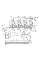
図1に示すように、画像形成装置100は、中間転写体の一例である中間転写ベルト51に沿ってトナー像形成手段の一例である画像形成部Pa、Pb、Pc、Pdを配列したタンデム型中間転写方式のフルカラープリンタである。画像形成部Pa、Pb、Pc、Pdは、記録材P上のトナー量がそれぞれ0.5mg/cm2のとき、定着後の反射濃度が概ね1.6になるように設定されている。
As shown in FIG. 1, an
画像形成部Paでは、感光ドラム1aにイエロートナー像が形成されて中間転写ベルト51に一次転写される。画像形成部Pbでは、感光ドラム1bにマゼンタトナー像が形成されて中間転写ベルト51のイエロートナー像に重ねて一次転写される。画像形成部Pc、Pdでは、それぞれ感光ドラム1c、1dにシアントナー像、ブラックトナー像が形成されて同様に中間転写ベルト51に順次重ねて一次転写される。
In the image forming portion Pa, a yellow toner image is formed on the
中間転写ベルト51に一次転写された四色のトナー像は、二次転写部T2へ搬送されて記録材Pへ一括二次転写される。四色のトナー像を二次転写された記録材Pは、定着装置7で加熱加圧を受けて表面にトナー像を定着された後に、画像形成装置100の外部へ排出される。
The four-color toner images primarily transferred to the
中間転写ベルト51は、テンションローラ52、駆動ローラ53、及び対向ローラ56に掛け渡して支持され、駆動ローラ53に駆動されて300mm/secのプロセススピードで矢印R2方向に回転する。中間転写ベルト51は、ポリイミド(PI)にカーボン粒子を含有させて体積抵抗率を108.5Ω・cmに調整した材料で厚み100μm、幅400mm、周長800mmに形成されている。体積抵抗率は、JIS−K6911法準拠プローブを使用して、印加電圧100V、印加時間60sdc、23℃50%RHにて測定した。ただし、PC、PDT、PVDFのような誘電体樹脂又は他の材料を用いて、異なる体積抵抗率及び厚みに形成してもよい。
The
記録材カセット8からピックアップローラ81により引き出された記録材Pは、分離ローラ82で1枚ずつに分離して、レジストローラ83へ送り出される。レジストローラ83は、停止状態で記録材Pを受け入れて待機させ、中間転写ベルト51のトナー像にタイミングを合わせて記録材Pを二次転写部T2へ送り込む。
The recording material P drawn from the recording material cassette 8 by the
二次転写ローラ57は、接地電位に接続された対向ローラ56との間に中間転写ベルト51を挟み込んで、中間転写ベルト51と二次転写ローラ57との間に二次転写部T2を形成する。電源D2から二次転写ローラ57へ直流電圧が印加されることにより、負極性に帯電して中間転写ベルト51に担持された4色のトナー像が、中間転写ベルト51に重ねて二次転写部T2にニップされた記録材Pへ二次転写される。
The
定着装置7は、内部にハロゲンランプヒータ73を設けた回転自在な定着ローラ71に加圧ローラ72を圧接しており、ハロゲンランプヒータ73への電圧を制御して定着ローラ71の表面温度を調節している。
The fixing device 7 presses a
画像形成部Pa、Pb、Pc、Pdは、それぞれの現像装置4a、4b、4c、4dで用いるトナーの色がイエロー、マゼンタ、シアン、ブラックと異なる以外は、ほぼ同一に構成される。以下では、画像形成部Paについて説明し、他の画像形成部Pb、Pc、Pdについては、説明中の符号末尾のaを、b、c、dに読み替えて説明されるものとする。
The image forming portions Pa, Pb, Pc, and Pd are configured substantially the same except that the color of the toner used in each of the developing
図2に示すように、画像形成部Paは、感光ドラム1aの周囲に、帯電ローラ2a、露光装置3a、現像装置4a、一次転写ローラ5a、クリーニング装置6aを配置している。
As shown in FIG. 2, in the image forming unit Pa, a charging
感光ドラム1aは、アルミニウムの導電性基体11の外周に帯電極性が負極性の光導電層12を形成した円筒状のOPC感光体である。感光ドラム1aは、回転軸線上に配置された支軸13を中心にして、300mm/secのプロセススピードで矢印R1方向に回転する。帯電ローラ2は、導電性の芯金21の外周に低抵抗導電層22と中抵抗導電層23とが形成され、芯金21の両端部を回転自在に軸支して感光ドラム1aの回転軸線に平行に配置されている。帯電ローラ2aは、感光ドラム1aに当接して従動回転し、直流電圧に交流電圧を重畳した振動電圧を電源D3から印加されることにより、感光ドラム1aの表面を一様な負極性の電位に帯電する。
The
露光装置3aは、イエローの分解色画像を展開した走査線画像データをON−OFF変調したレーザビームを回転ミラーで走査して、帯電した感光ドラム1aの表面に画像の静電像を書き込む。
The
現像装置4aは、現像容器41に充填された二成分現像剤を攪拌スクリュー45、46で攪拌して、二成分現像剤中の磁性キャリアを正極性、非磁性トナーを負極性にそれぞれ帯電させる。現像スリーブ42は、固定磁極43の周囲で感光ドラム1aに対してカウンタ方向に回転して、層厚規制ブレードで層厚規制された二成分現像剤を磁気的に担持して感光ドラム1aへ摺擦させる。電源D4は、負極性の直流電圧に交流電圧を重畳した振動電圧を現像スリーブ42へ印加する。これにより、負極性に帯電したトナーが、現像スリーブ42よりも相対的に正極性となった感光ドラム1aの静電像へ移転して、静電像が反転現像される。
The developing device 4a agitates the two-component developer filled in the developing container 41 with the agitating screws 45 and 46, and charges the magnetic carrier in the two-component developer to positive polarity and the non-magnetic toner to negative polarity, respectively. The developing
一次転写ローラ5aは、芯金の外周面に円筒状の導電層を配置して構成され、両端部がスプリング(図示略)によって感光ドラム1aに向けて付勢される。これにより、一次転写ローラ5aは、所定の押圧力で中間転写ベルト51を押圧して、感光ドラム1aと中間転写ベルト51との間に一次転写部T1を形成する。電源D1から正極性の直流電圧が一次転写ローラ5aに印加されることにより、感光ドラム1aに担持された負極性のトナー像が、一次転写部T1を通過する中間転写ベルト51へ一次転写される。
The
クリーニング装置6aは、クリーニングブレード61を所定の角度と圧力でもって加圧手段(図示略)によって感光ドラム1aに当接させる。クリーニング装置6aは、クリーニングブレード61を感光ドラム1aに摺擦して、一次転写部T1を通過して感光ドラム1aの表面に残留した転写残トナーを掻き落として回収容器62に回収する。
The cleaning device 6a brings the cleaning blade 61 into contact with the
図1に示すように、画像形成装置100は、テスト画像測定モードにおいて、各色のトナー載り量(画像濃度)を試験的に検知するためのテスト画像(パッチトナー像)を中間転写ベルト51上に形成する。それらのパッチトナー像のパッチ濃度を検知して目標濃度と比較することによって、画像形成部Pa、Pb、Pc、Pdにおける画像形成条件にフィードバックする、所謂トナー濃度制御が為される。調整される画像形成条件は、露光装置の露光量、現像スリーブに印加される直流電圧、階調補正カーブ、濃度補正テーブル等である。これにより、記録材上に形成されるフルカラー画像のトナー濃度を適切に制御して、色調が安定したカラー画像を得ることができる。
As shown in FIG. 1, in the test image measurement mode, the
しかし、テスト画像測定モードでは画像形成装置100が本来行うべき画像形成とは異なった動作を必要とする。このため、テスト画像測定モードが割り込まれると、出力される画像と画像との間隔に制御を割りこませてパッチトナー像を読み込む動作が行われる。
However, in the test image measurement mode, the
イエロー、マゼンタ、シアン、ブラックの4色のトナー像が形成される従来の画像形成装置では、図3の(a)に示すように、4色分のパッチトナー像を形成するために余分に画像間隔を空ける必要がある。このため、ダウンタイムが増大して好ましい状況ではなかった。 In a conventional image forming apparatus in which toner images of four colors of yellow, magenta, cyan, and black are formed, an extra image is formed to form a patch toner image for four colors as shown in FIG. Need to be spaced. For this reason, the downtime is increased, which is not a preferable situation.
ダウンタイムを短縮するために、例えば、パッチトナー像の搬送方向に対する長さを短くして、制御時間を短縮することが可能である。しかし、パッチトナー像の濃度を検知する場合、パッチトナー像の長さを短くすることは、濃度バラツキや検知バラツキの影響を受け易くなるため、濃度検知の精度を落とす恐れがあり好ましくない。パッチトナー像内の濃度ばらつきや検知のばらつきを考慮して、パッチトナー像内で濃度検知を所定回数繰り返して平均値を用いているため、回数が減ると誤差が増えるからである。 In order to shorten the downtime, for example, the length of the patch toner image in the conveyance direction can be shortened to shorten the control time. However, when detecting the density of a patch toner image, it is not preferable to shorten the length of the patch toner image because it is likely to be affected by density variations and detection variations, and this may reduce the accuracy of density detection. This is because the average value is used by repeating the density detection within the patch toner image a predetermined number of times in consideration of the density variation and detection variation within the patch toner image, so that the error increases as the number of times decreases.
従って、本実施形態の画像形成装置100では、図3の(b)、(c)に示すように、複数色のパッチトナー像を中間転写ベルト51に転写して重ね合わせる。そして、中間転写ベルト上の重なったパッチトナー像の検出結果から、各色のパッチトナー像のトナー載り量(画像濃度又はトナー濃度)を演算する。重ねた多次色パッチトナー像を形成して、多次色パッチトナー像を読み込むことで、パッチトナー像の測定時間を減らして、大幅にダウンタイムを短縮することが可能になる。
Therefore, in the
しかし、パッチトナー像の濃度測定センサとしては、特許文献2に示されるように、赤外光を照射して照射部の反射光又は拡散光を検知してトナー濃度を検出する光学式センサが一般的である。そして、光学式センサを用いた場合、複数色が重なったパッチトナー像を検出して各色のパッチトナー像のトナー載り量を求めることは困難である。
However, as a sensor for measuring the density of a patch toner image, an optical sensor that detects the toner density by irradiating infrared light and detecting reflected light or diffused light of an irradiation part is generally used as disclosed in
すなわち、光学式センサは、トナーの色情報を直接検知しているわけではない。光学式センサが検知できる情報は、赤外光の照射に対するトナー像部と非トナー像部(中間転写ベルト表面)とにおける反射光(又は拡散光)の差分量である。つまり、中間転写ベルト表面をトナーが被覆している面積をトナー載り量として検知している。このため、二色のパッチトナー像が重なった二次色パッチトナー像を検知した場合、二色合計のトナー量(トナー被覆面積)を検知することは可能だが、各色のトナー載り量を区別して検知することはできない。 That is, the optical sensor does not directly detect the color information of the toner. The information that can be detected by the optical sensor is the difference amount of the reflected light (or diffused light) between the toner image portion and the non-toner image portion (intermediate transfer belt surface) in response to infrared light irradiation. That is, the area where the toner covers the surface of the intermediate transfer belt is detected as the amount of applied toner. Therefore, when detecting a secondary color patch toner image in which two color patch toner images overlap, it is possible to detect the total toner amount (toner coverage area) of the two colors, but distinguishing the amount of applied toner for each color. It cannot be detected.
このため、従来の光学式センサを用いる限り、フルカラー画像形成装置において各色の濃度を管理するためには、図3の(a)に示すように、各色ごとにパッチトナー像を測定する必要がある。このため、ダウンタイムの増加もしくはランニングコストアップの弊害が発生して好ましい状況ではなかった。 Therefore, as long as a conventional optical sensor is used, in order to manage the density of each color in the full-color image forming apparatus, it is necessary to measure a patch toner image for each color as shown in FIG. . For this reason, an adverse effect of an increase in downtime or an increase in running cost occurs, which is not a preferable situation.
そこで、画像形成装置100では、各色のハーフトーントナー像がモアレを避けるために異なるスクリーンパターンで形成されていることを利用して、重なったパッチトナー像の検知結果を各色に分離する。これにより、最小限のダウンタイムでフルカラー画像形成装置における各色の濃度を、精度よく検知及び制御することを可能にしている。
Therefore, the
すなわち、トナー像形成手段の一例である画像形成部Pa、Pb、Pc、Pdは、スクリーン角度とスクリーン線数のうち少なくとも一方が異なるように第1の色のトナー像と第2の色のトナー像を画像搬送体の一例である中間転写ベルト51に重ねて形成する。
In other words, the image forming portions Pa, Pb, Pc, and Pd, which are examples of toner image forming means, have a first color toner image and a second color toner so that at least one of the screen angle and the screen line number is different. The image is formed so as to overlap an
高さ分布検出手段(30)は、トナー像の回転方向の高さ分布を測定するように中間転写体(51)の回転に伴って中間転写体上のパッチトナー像の高さを検出する。高さ分布検出手段(30)は、レーザ光を照射して照射面を三角測距するレーザ変位センサである。トナー高さセンサ30の検知対象は、複数色を同一領域で重ね合わせた多次色パッチトナー像である。トナー高さセンサ30は、複数色のパッチトナー像が重なって通過する位置に配置される。
The height distribution detecting means (30) detects the height of the patch toner image on the intermediate transfer body as the intermediate transfer body (51) rotates so as to measure the height distribution in the rotation direction of the toner image. The height distribution detecting means (30) is a laser displacement sensor that irradiates a laser beam and triangulates the irradiated surface. A detection target of the
テスト画像測定モードでは、画像形成部Pa、Pb、Pc、Pdにより、複数色のパッチトナー像を画像と画像の間隔で形成して中間転写体(51)に転写して重ね合わせる。パッチトナー像は、ハーフトーン画像のトナー像である。 In the test image measurement mode, a plurality of color patch toner images are formed at intervals between images by the image forming portions Pa, Pb, Pc, and Pd, transferred to the intermediate transfer member (51), and superimposed. The patch toner image is a toner image of a halftone image.
制御部50は、高さ分布検出手段(30)を用いて検出された「重なったパッチトナー像」の回転方向の高さ分布を周波数解析して個別のパッチトナー像のトナー載り量を演算する。制御部50は、重なったパッチトナー像の回転方向の高さ分布を一次元フーリエ解析して周波数分布曲線を求め、周波数分布曲線上のピークごとにピーク下の積分値に応じたトナー載り量を出力する。
The
<テスト画像測定モード>
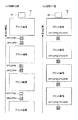
図4はトナー高さセンサの説明図である。図5はトナー載り量検知制御のフローチャートである。図6はパッチトナー像の回転方向の高さ分布の周波数解析のフローチャートである。
<Test image measurement mode>
FIG. 4 is an explanatory diagram of the toner height sensor. FIG. 5 is a flowchart of applied toner amount detection control. FIG. 6 is a flowchart of frequency analysis of the height distribution in the rotation direction of the patch toner image.
図1に示すように、画像形成部Pa、Pb、Pc、Pdは、各色についてそれぞれ異なるスクリーン角度のスクリーンパターンを用いてハーフトーン処理を施した潜像パターンでトナー像を形成している。スクリーン角度は、中間転写ベルト51上にトナー像が形成された際に、中間転写ベルト51の回転方向を0°として、回転方向に対して時計回りの角度差で示される。イエローはスクリーン角度が90°、マゼンタはスクリーン角度が45°、シアンはスクリーン角度が57°、ブラックはスクリーン角度が13°であって、全て200線/inchのハーフトーン処理を行っている。
As shown in FIG. 1, the image forming portions Pa, Pb, Pc, and Pd form toner images with latent image patterns that have been subjected to halftone processing using screen patterns having different screen angles for the respective colors. The screen angle is indicated by a clockwise angle difference with respect to the rotation direction when the toner image is formed on the
重なったパッチトナー像を検出して各色に分離するために、各色のパッチトナー像の高さ分布の空間周波数が重複しないように、同一線数における各色スクリーン角度は異なっている必要がある。そして、例えば10°と170°のような搬送方向に対して線対称になるような角度も搬送方向の空間周波数が重複するので好ましくない。また、検出される空間周波数が低過ぎると周波数分析に支障があるので、各色スクリーン角度は少なくとも10°以上の角度を中間転写ベルト51の搬送方向に対して成すことが望ましい。
In order to detect the overlapping patch toner images and separate them into colors, the color screen angles in the same line number need to be different so that the spatial frequencies of the height distribution of the patch toner images of the respective colors do not overlap. For example, an angle that is line-symmetric with respect to the transport direction such as 10 ° and 170 ° is not preferable because the spatial frequency in the transport direction overlaps. In addition, if the detected spatial frequency is too low, frequency analysis is hindered, so it is desirable that each color screen angle is at least 10 ° or more with respect to the conveyance direction of the
トナー高さセンサ30は、中間転写ベルト51の回転方向における画像形成部Pdの下流側に配置されて、中間転写ベルト51に転写して重ねた複数のパッチトナー像の高さ分布を測定する。
The
パッチトナー像の高さ分布を所定の精度で測定するためには、トナー高さセンサ30と中間転写ベルト51との距離を所定値に保つ必要がある。中間転写ベルト51が駆動中のバタツキによってトナー高さセンサ30と中間転写ベルト51の表面との距離が振れると、パッチトナー像の高さの測定誤差になるからである。
In order to measure the height distribution of the patch toner image with a predetermined accuracy, it is necessary to keep the distance between the
そこで、中間転写ベルト51の内側面が駆動ローラ53に支持された位置にトナー高さセンサ30を配置している。この位置であれば、駆動ローラ53のバックアップによって中間転写ベルト51には一定の張力が付与されて駆動ローラ53と一体に回転しており、パッチトナー像が形成される中間転写ベルト51の走行面が振動することなく所定高さに位置決められるからである。これにより、トナー高さセンサ30は、中間転写ベルト51との距離を固定されて、精度良くパッチトナー像の高さ情報を測定できる。
Therefore, the
図4に示すように、トナー高さセンサ30は、光源としての半導体レーザ31から射出した光ビームの反射光を受光素子としてのCCD32で検出して三角測距を行うレーザ変位センサである。
As shown in FIG. 4, the
半導体レーザ31は、駆動回路36に駆動されて測定用の光ビームとしてレーザ光を出力する光源である。半導体レーザ31から出力された光ビームは、コリメータレンズ33によって平行光に整形され、被測定物であるパッチトナー像CPに達して照射スポットを形成する。CCD32は、半導体レーザ31の入射光軸に対して傾いた出射光軸上に配置され、パッチトナー像CPからのレーザ光の反射光は、結像レンズ34によってCCD32上に結像する。
The
CCD32が入射光軸に対して傾いた出射光軸上に配置されているので、パッチトナー像CPの表面の高さがh1の場合には、CCD32上の位置p1に照射スポットの光像が形成される。そして、パッチトナー像CPの表面の高さがh2の場合はCCD32上の位置p2に、パッチトナー像CPの表面の高さがh3の場合はCCD32上の位置p3に照射スポットの光像が形成される。
Since the
このように、CCD32上の光像の結像位置は、パッチトナー像CPの表面の高さに応じて変化し、CCD32からは、光像の結像位置に応じたレベルの信号が出力される。そして、パッチトナー像CPは、中間転写ベルト51と一体に300mm/secの一定速度で回転しているため、CCD32からは、中間転写ベルト51の回転方向におけるパッチトナー像CPの高さ分布に応じた時系列の信号が出力される。
In this way, the image formation position of the optical image on the
CCD32の出力は、増幅回路37で増幅して演算制御回路35に読み取られる。演算制御回路35は、駆動回路36を制御して半導体レーザ31の出力を制御するとともに、増幅回路37の出力を所定の間隔でサンプリングして二値データに変換し、連続的に出力する。
The output of the
トナー高さセンサ30における半導体レーザ31のレーザスポット径は30μm、高さ方向の測定分解能は0.1μm、回転方向の分解能(サンプリング間隔)は10μm程度である。
The laser spot diameter of the
制御部50は、演算制御回路35から出力されるパッチトナー像CPの高さ情報を演算することで、パッチトナー像CPのトナー載り量(単位面積当たりのトナー量)を算出する。
The
制御部50は、テスト画像測定モードが指令されると、複数色のパッチトナー像を形成して、中間転写ベルト51に転写して重ね合わせる。重なったパッチトナー像をトナー高さセンサ30により検出して各色のパッチトナー像のトナー載り量を演算する。ここでは、画像形成の開始に先立って実行されるテスト画像測定モードとしてのトナー載り量検知制御を説明する。
When the test image measurement mode is commanded, the
図1を参照して図5に示すように、制御部50は、トナー載り量検知制御が指令されると、中間転写ベルト51の駆動を開始して(S700)、トナー高さセンサ30の半導体レーザ(31:図4)を点灯する(S701)。
As shown in FIG. 5 with reference to FIG. 1, when the toner application amount detection control is instructed, the
制御部50は、トナー高さセンサ30を用いてトナー像の高さを正確に読み取るために、トナー高さセンサ30を用いてトナー像が全く形成されていないブランク状態で、中間転写ベルト51の高さを読み取る(S702)。読み取ったブランク状態のデータは、後述するトナー像の高さ情報値の補正データとして用いる。
In order to accurately read the height of the toner image using the
制御手段(50)は、検出手段(30)により検出された第1の色のテスト画像と第2の色のテスト画像の高さ分布に基づき、トナー像形成手段(Pa、Pb、Pc、Pd)によるトナー像形成条件を制御する。すなわち、制御部50は、画像形成部Pa、Pb、Pc、Pdに対して所定の帯電条件、露光条件、現像条件を設定して、所定のパッチトナー像の静電像を感光ドラム1a、1b、1c、1dに書き込む。そして、現像スリーブ(42:図2)に所定の振動電圧を印加することで、各色のパッチトナー像を形成し、中間転写体ベルト51に各色のパッチトナー像を一次転写する(S703)。
The control means (50) is configured to generate toner image forming means (Pa, Pb, Pc, Pd) based on the height distribution of the first color test image and the second color test image detected by the detection means (30). ) To control the toner image forming conditions. That is, the
ここで、各色のパッチトナー像は、上述したように各色で異なるハーフトーン処理を施しており、中間転写ベルト51上で、パッチトナー像が重なるように静電像の書き出しタイミングを制御している。重ね合わせのタイミングについては、通常の画像形成と同様に行われる公知の制御のため、詳細な説明は省略する。
Here, the patch toner images of the respective colors are subjected to different halftone processes for the respective colors as described above, and the electrostatic image writing timing is controlled on the
重なったパッチトナー像(多次色トナー像)は、中間転写ベルト51の回転に伴って、トナー高さセンサ30を300mm/secの速度で通過する。制御部50は、重なったパッチトナー像がトナー高さセンサ30を通過する過程で、トナー高さセンサ30を用いてトナー高さ情報を連続的に検出する(S704)。これにより、重なったパッチトナー像の回転方向の高さ分布が測定される。
The overlapped patch toner image (multi-order color toner image) passes through the
制御部50は、重なったパッチトナー像の回転方向の高さ分布の測定後、中間転写ベルト51の駆動を停止して(S705)、半導体レーザを消灯させる(S706)。制御部50は、重なったパッチトナー像の回転方向の高さ分布を、下地情報(S702)で補正した後に周波数解析して、各色の個別のパッチトナー像のトナー載り量を算出する(S707)。
After measuring the height distribution in the rotation direction of the overlapping patch toner images, the
なお、画像間隔(紙間)で実行されるテスト画像測定モードでは、図5のステップS700で前の画像の書き込みを行った後にトナー載り量検知制御が同様に実行され、トナー載り量検知制御の終了後に次の画像の書き込みが実行される。 Note that, in the test image measurement mode executed at the image interval (paper interval), the applied toner amount detection control is similarly executed after the previous image is written in step S700 of FIG. 5, and the applied toner amount detection control is performed. After the end, writing of the next image is executed.
図4を参照して図6に示すように、制御部50は、トナー高さセンサ30を用いて検出したパッチトナー像CPの回転方向の高さ分布データを処理する。
As shown in FIG. 6 with reference to FIG. 4, the
中間転写ベルト51の矢印R2方向の回転に伴ってトナー高さセンサ30がパッチトナー像CPの回転方向の高さ分布を読み込む(S800)。すなわち、パッチトナー像CPが中間転写ベルト51に搬送されてトナー高さセンサ30を通過する過程で、パッチトナー像の高さ分布がトナー高さセンサ30によって連続的に検出される。
As the
演算処理部50bは、下地(中間転写ベルト51)の高さをゼロ点としてパッチトナー像の高さ分布を補正して高さ分布データ(図12)を作成してメモリ50aに記憶する(S801)。
The
測定終了後、演算処理部50bは、重なったパッチトナー像の高さ分布データ(図12)をメモリ50aから呼び出して一次元フーリエ変換を行う(S802)。一次元フーリエ変換によって、回転方向の空間周波数ごとにピークが配置された周波数分析結果が得られる(図13)。周波数分析されたパッチトナー像の高さ分布データは、回転方向の空間周波数の違いによって重なった数のピークに分割され、それぞれのピーク下の面積が各色のトナー載り量に対応している(図14)。
After the measurement is completed, the
ここで、ピークの信号強度は、トナー載り量に相当しているため、信号強度からトナー載り量に演算可能になっている。しかし、パッチトナー像は、静電像に対して現像及び転写を経てある程度のばらつきをもって形成されているので、フーリエ変換後の信号強度は所定の空間周波数ごとに分布を持つ。 Here, since the peak signal intensity corresponds to the applied toner amount, it is possible to calculate the applied toner amount from the signal intensity. However, since the patch toner image is formed with a certain degree of variation after being developed and transferred to the electrostatic image, the signal intensity after Fourier transform has a distribution for each predetermined spatial frequency.
演算処理部50bは、続いて、各ピーク領域を分離しての積分値を演算して(S803)トナー載り量に換算する(S804)。このとき、所定レベル以下の周波数に依存が無い微弱な強度分布部分は、スクリーンパターンに依存しないかぶりトナー等の影響であり、そもそものトナー載り量に対して微小量であるために、積分領域から除いている(図14の実線以下の領域)。その結果、トナー載り量として扱う積分領域は、ピークについて求める所定レベル以上の強度が高い領域である(S803)。
Subsequently, the
演算処理部50bは、積分値に対するトナー載り量の関係(図15)を用いて、個別のピークごとの積分値を各色のパッチトナー像のトナー載り量に換算する(S804)。
The
このように、各色のスクリーン角度を搬送方向のトナー載り量の周期性が変わるように設定しておき、トナー高さセンサ30によってトナー載り量の高さを一体に測定した後にスクリーン角度から計算される特定周期数の出力値に分離する。このため、従来の光学センサ方式では困難であった重なったパッチトナー像を用いて各色別のトナー載り量を検知可能になる。これにより、フルカラー画像形成装置における4色分のパッチトナー像を形成するための余分なダウンタイムを大幅に短縮することが可能になる。
In this way, the screen angle of each color is set so that the periodicity of the toner application amount in the transport direction changes, and the height of the toner application amount is integrally measured by the
<実施例1>
図7は実施例1におけるパッチトナー像の配置の説明図である。図8は個別のパッチトナー像の説明図である。図9は重なったパッチトナー像の説明図である。図10はイエローパッチトナー像の検出信号とマゼンタパッチトナー像の検出信号である。図11は重なったパッチトナー像の検出信号である。図12は重なったパッチトナー像の検出信号の周波数分析結果である。図13は積分処理の説明図である。図14は積分値とトナー載り量との関係の説明図である。
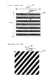
<Example 1>
FIG. 7 is an explanatory diagram of the arrangement of patch toner images in the first embodiment. FIG. 8 is an explanatory diagram of individual patch toner images. FIG. 9 is an explanatory diagram of overlapping patch toner images. FIG. 10 shows a detection signal for a yellow patch toner image and a detection signal for a magenta patch toner image. FIG. 11 is a detection signal of the overlapping patch toner images. FIG. 12 shows the frequency analysis result of the detection signals of the overlapping patch toner images. FIG. 13 is an explanatory diagram of the integration process. FIG. 14 is an explanatory diagram of the relationship between the integral value and the applied toner amount.
図7に示すように、実施例1では、画像と画像との間隔にイエローパッチトナー像とマゼンタパッチトナー像とを重ねて形成する。イエローパッチトナー像とマゼンタパッチトナー像は、トナー高さセンサ30が通過する位置に、それぞれ搬送方向に20mm、中間転写ベルト51の幅方向に20mmの正方形に形成される。
As shown in FIG. 7, in the first embodiment, a yellow patch toner image and a magenta patch toner image are formed so as to overlap each other between images. The yellow patch toner image and the magenta patch toner image are formed into squares of 20 mm in the transport direction and 20 mm in the width direction of the
図8の(a)に示すように、感光ドラム(1a:図1)には、イエローパッチトナー像CPYが、スクリーン角度を搬送方向に対して90°とし、スクリーンの解像度を200線/inch(1インチ当り200本の線画像)として形成される。このため、搬送方向で見たイエローパッチトナー像CPYのスクリーンピッチ(線間距離)は、0.127(25.4mm÷200線)mmである。 As shown in FIG. 8A, on the photosensitive drum (1a: FIG. 1), the yellow patch toner image CPY has a screen angle of 90 ° with respect to the transport direction and a screen resolution of 200 lines / inch (in FIG. 8). 200 line images per inch). Therefore, the screen pitch (distance between lines) of the yellow patch toner image CPY viewed in the transport direction is 0.127 (25.4 mm ÷ 200 lines) mm.
図8の(b)に示すように、感光ドラム(1b:図1)には、マゼンタパッチトナー像CPMが、スクリーン角度を搬送方向に対して45°とし、スクリーンの解像度を200線/inchとして形成される。このため、搬送方向で見たマゼンタパッチトナー像CPMのスクリーンピッチ(線間距離)は、0.170(25.4mm÷200線÷Sin45°)mmである。 As shown in FIG. 8B, on the photosensitive drum (1b: FIG. 1), the magenta patch toner image CPM has a screen angle of 45 ° with respect to the transport direction and a screen resolution of 200 lines / inch. It is formed. Therefore, the screen pitch (distance between lines) of the magenta patch toner image CPM viewed in the transport direction is 0.170 (25.4 mm ÷ 200 lines ÷ Sin45 °) mm.
図9に示すように、中間転写ベルト(51:図1)には、イエローパッチトナー像CPYにマゼンタパッチトナー像CPMが重ねて転写される。重なるように、それぞれの感光ドラム(1a、1b:図1)で露光タイミングが制御されている。そして、中間転写ベルト51は、プロセススピード300mm/secで駆動しているため、トナー高さセンサ30を用いて連続的に測定したパッチトナー像の高さ分布は、振動パターンを形成する。
As shown in FIG. 9, on the intermediate transfer belt (51: FIG. 1), the magenta patch toner image CPM is transferred onto the yellow patch toner image CPY. The exposure timing is controlled by the respective photosensitive drums (1a, 1b: FIG. 1) so as to overlap. Since the
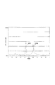
図10の(a)に示すように、イエローパッチトナー像CPYのみが中間転写ベルト51に転写されている場合、イエローパッチトナー像のスクリーン線は、0.420msec(0.127mm÷300mm/sec)の時間間隔で検知される。また、図10の(b)に示すように、マゼンタパッチトナー像CPMのみが中間転写ベルト51に転写されている場合、マゼンタパッチトナー像のスクリーン線は、0.590msec(0.170mm÷300mm/sec)の時間間隔で検知される。
As shown in FIG. 10A, when only the yellow patch toner image CPY is transferred to the
図11に示すように、イエローパッチトナー像CPYとマゼンタパッチトナー像CPMとが重なっている場合、図10の(a)、(b)に示す2つの空間周波数パターンが重畳した高さ情報の空間周波数パターンが測定される。図10の(a)、(b)のように単色カラーパッチ像の場合の周期性は明らかに判別可能だが、重なったカラーパッチ像である多次色パッチ像の場合は明確な周期が判別しにくくなる。 As shown in FIG. 11, when the yellow patch toner image CPY and the magenta patch toner image CPM overlap, a space of height information in which two spatial frequency patterns shown in FIGS. A frequency pattern is measured. As shown in FIGS. 10A and 10B, the periodicity in the case of a single color patch image can be clearly discriminated, but in the case of a multi-color patch image that is an overlapping color patch image, a clear cycle is discriminated. It becomes difficult.
よって、イエローとマゼンタを重ねた多次色パッチ像の高さ情報を中間転写ベルト51の搬送方向の一次元フーリエ変換によって周波数分析して、各色のスクリーン線パターンを分離している。なお、一次元フーリエ変換の演算に関しては、当業者には公知の数値計算法のため詳細な説明は省略する。
Accordingly, the height information of the multi-color patch image in which yellow and magenta are superimposed is subjected to frequency analysis by one-dimensional Fourier transform in the conveyance direction of the
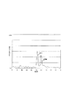
図12に示すように、イエローとマゼンタの周期パターンが重畳した高さ情報信号を一次元フーリエ変換すると、周期0.420msec位置のイエローピークと、周期0.590msecのマゼンタピークとが分離される。 As shown in FIG. 12, when a one-dimensional Fourier transform is performed on the height information signal in which the yellow and magenta periodic patterns are superimposed, a yellow peak at a period of 0.420 msec and a magenta peak at a period of 0.590 msec are separated.
分離された0.420msecと0.590msecのピーク高さは、中間転写ベルト51上のトナー高さに相当している。そして、トナー像は、静電像に対して現像工程及び転写工程を経てある程度のばらつきをもって形成されているため、一次元フーリエ変換された高さ情報信号は、ピークごとの分布を持っている。このため、ピーク下の面積がトナー載り量に対応しており、積分演算によってトナー載り量を求められる。
The separated peak heights of 0.420 msec and 0.590 msec correspond to the toner height on the
図13に示すように、実施形1では、黒(マゼンタ)及びグレー(イエロー)の各領域の積分値を求めてトナー載り量に換算している。ここで、トナー載り量として扱う積分領域は、実線LLよりも信号強度が高い領域である。実線LLより下部の周波数依存が希薄な微弱な強度領域はスクリーンパターンに依存しない例えばかぶりトナー等の影響であるため、積分領域から除かれる。ピークにおける実線LLより下部の強度領域は、カラーパッチのトナー載り量に対して微小量であるために積分領域から除かれても大きな誤差は招かない。 As shown in FIG. 13, in the first embodiment, the integral value of each area of black (magenta) and gray (yellow) is obtained and converted to the applied toner amount. Here, the integration region treated as the toner application amount is a region where the signal intensity is higher than that of the solid line LL. The weak intensity region below the solid line LL having a low frequency dependence is excluded from the integration region because of the influence of, for example, fog toner that does not depend on the screen pattern. Since the intensity region below the solid line LL at the peak is a minute amount with respect to the amount of toner on the color patch, even if it is removed from the integration region, a large error does not occur.
図14に示すように、演算された積分値がトナー載り量に換算される。図14の関係からイエローカラーパッチCPYのトナー載り量は0.15mg/cm2、マゼンタカラーパッチCPMのトナー載り量は0.18mg/cm2と算出された。 As shown in FIG. 14, the calculated integral value is converted into a toner applied amount. From the relationship of FIG. 14, the applied toner amount of the yellow color patch CPY was calculated to be 0.15 mg / cm 2 , and the applied toner amount of the magenta color patch CPM was calculated to be 0.18 mg / cm 2 .
このようにして重なったパッチトナー像から得られたイエロー/マゼンタのトナー載り量は、従来の光学式センサで個別に測定した単色トナー濃度(トナー載り量)と同様の値であった。このため、このようにして測定したトナー載り量をフィードバックする濃度制御等を従来通りの制御で実施できる。 The amount of applied toner of yellow / magenta obtained from the overlapping patch toner images in this way was the same value as the monochromatic toner density (toner applied amount) individually measured by a conventional optical sensor. For this reason, it is possible to carry out density control or the like for feeding back the amount of applied toner thus measured by conventional control.
例えば、予め所定の画像形成条件(帯電、露光、現像)によって得られた各色のパッチトナー像のトナー載り量を基準載り量に設定する。そして、基準トナー載り量と上記で算出されたトナー載り量とを比較して、所定量以上異なる場合は画像形成条件(帯電、露光、現像)を調整し、最適な現像コントラストを設定してトナー載り量を一定値に収束させる。 For example, the toner loading amount of each color patch toner image obtained in advance under predetermined image forming conditions (charging, exposure, development) is set as the reference loading amount. Then, the reference toner applied amount and the toner applied amount calculated above are compared, and if they differ by a predetermined amount or more, the image forming conditions (charging, exposure, development) are adjusted, and an optimum development contrast is set to set the toner. The loading amount is converged to a constant value.
ところで、実施例1では、空間周波数の異なるパッチトナー像の高さ情報信号を一次元フーリエ変換によって周波数解析している。このため、スクリーン角度が搬送方向に対して平行、すなわち角度0°の場合、パッチトナー像の搬送時にスクリーン線とトナー高さセンサ30とが交差しないので、空間周波数が形成されず、周波数解析もできない。
In the first embodiment, the height information signals of patch toner images having different spatial frequencies are subjected to frequency analysis by one-dimensional Fourier transform. For this reason, when the screen angle is parallel to the transport direction, that is, when the angle is 0 °, the screen line and the
従って、搬送方向20mmの大きさでスクリーン線数が200線のパッチトナー像の場合、少なくとも搬送方向に対して25°以上のスクリーン角度が望ましい。この理由は、一次元フーリエ変換後の周波数解析の精度は、検知されるスクリーン線の本数に依存するためである。スクリーン角度を異ならせた比較実験の結果、スクリーン線の検知本数が64以上のとき、算出したトナー載り量と実際のトナー載り量との差異が製品仕様上問題ないレベルになることが確認された。そのうえで、スクリーン角度は25°以上であることが望ましい。 Accordingly, in the case of a patch toner image having a size of 20 mm in the transport direction and a screen line number of 200 lines, a screen angle of at least 25 ° with respect to the transport direction is desirable. This is because the accuracy of frequency analysis after the one-dimensional Fourier transform depends on the number of screen lines to be detected. As a result of a comparative experiment with different screen angles, it was confirmed that when the number of screen lines detected was 64 or more, the difference between the calculated amount of applied toner and the actual amount of applied toner was at a level where there was no problem in product specifications. . In addition, the screen angle is preferably 25 ° or more.
また、同一スクリーン線数(本/inch)の場合、角度30°のスクリーン線と角度150°のスクリーン線とのように、中間転写ベルト51の搬送方向に対して線対称なスクリーンパターンは、周波数解析で分離できない。搬送方向におけるトナー高さ分布の周期が同じになるため一次元フーリエ変換した際にピークが重なり合ってしまうからである。
In the case of the same number of screen lines (lines / inch), a screen pattern that is line-symmetric with respect to the conveyance direction of the
このため、同一スクリーン線数における各色のスクリーン角度は、少なくともいずれも異なり、中間転写ベルト51の搬送方向に対して非対称に配置されて10°以上の角度を成している必要がある。
For this reason, at least all of the screen angles of the respective colors with the same number of screen lines need to be different from each other and arranged asymmetrically with respect to the conveyance direction of the
実施例1では、複数色を重ねたパッチ像をトナー高さセンサで読み込み、周波数解析によって各色のトナー高さに切り分けて検出することが可能である。このため、従来の単色毎の濃度検知に比べて、トナー載り量の管理精度を落とすことなく、複数色を一括して検出可能であるために、制御に要するダウンタイムを大幅に削減可能である。 In the first embodiment, it is possible to read a patch image in which a plurality of colors are overlapped with a toner height sensor, and to detect by dividing into toner heights of each color by frequency analysis. For this reason, compared to the conventional density detection for each single color, a plurality of colors can be detected at once without reducing the accuracy of controlling the applied toner amount, so that the downtime required for control can be greatly reduced. .
なお、実施例1ではイエローとマゼンタの2色を重ねた多次色パッチを例に挙げて説明したが、3色又は4色を重ね合わせた状態で、同時に搬送方向のトナー高さ分布を測定することも可能である。例えば、実施例1では、上述したように、イエロー、マゼンタ、シアン、ブラックが同一のスクリーン線数でそれぞれスクリーン角度が異なり、搬送方向に対してスクリーン線が非対象である。このため、中間転写ベルト51の搬送方向のトナー高さ分布における周期が各色で異なる。よって、実施例1と同様の一次元フーリエ変化による周波数解析を行うことで、4色のパッチ像から各色のトナー載り量を分離して算出可能である。
In the first embodiment, a multi-order color patch in which two colors of yellow and magenta are overlapped is described as an example, but the toner height distribution in the transport direction is measured at the same time in a state where three or four colors are overlapped. It is also possible to do. For example, in the first embodiment, as described above, yellow, magenta, cyan, and black have the same number of screen lines and different screen angles, and the screen lines are untargeted with respect to the transport direction. For this reason, the period in the toner height distribution in the conveyance direction of the
また、実施例1ではイエロー1階調とマゼンタ1階調とを重ねた1個の多次色パッチトナー像を画像間隔に形成したが、イエロー複数階調とマゼンタ複数階調とを重ねた複数個の多次色パッチトナー像を画像間隔に形成してもよい。露光装置3aの露光条件を異ならせて複数階調の多次色パッチ像を形成し、それぞれ同様に一次元フーリエ変換による周波数分析を行って各階調におけるトナー載り量を制御することも勿論可能である。
In the first embodiment, one multi-order color patch toner image in which one yellow gradation and one magenta gradation are overlapped is formed in the image interval, but a plurality of yellow multiple gradations and a plurality of magenta gradations are overlapped. Multiple multi-color patch toner images may be formed at image intervals. It is of course possible to form a multi-gradation multi-color patch image with different exposure conditions of the
<実施例2>
図15は実施例2における重なったパッチトナー像の検出信号の周波数分析結果である。
<Example 2>
FIG. 15 shows the frequency analysis results of the detection signals of the overlapping patch toner images in Example 2.
実施例1では、重ねたイエローとマゼンタのパッチトナー像が同一の200線/inchスクリーン線数でスクリーン角度のみが異なる例を説明した。これに対して実施例2では、イエローがスクリーン線数160線/inch、マゼンタがスクリーン線数200線/inchの組み合わせで重ねている。スクリーン角度は、実施例1と同様に、イエローが90°、マゼンタが45°である。そして、スクリーン線数以外の構成及び制御は実施例1と同様であるため、重複する説明を省略する。 In the first embodiment, an example in which the overlapping yellow and magenta patch toner images have the same number of 200 lines / inch screen lines and only the screen angles are different has been described. On the other hand, in Example 2, yellow is overlaid with a combination of 160 screen lines / inch and magenta is over a combination of 200 lines / inch of screen lines. As in Example 1, the screen angles are 90 ° for yellow and 45 ° for magenta. Since the configuration and control other than the number of screen lines are the same as those in the first embodiment, redundant description is omitted.
スクリーン線数160線/inchのイエローパッチトナー像の空間周波数は0.159mm(25.4mm÷160線)である。マゼンタパッチトナー像の空間周波数は実施例1と同様に0.170mm(25.4mm÷200線÷Sin45°)である。そして、中間転写ベルト51の搬送速度は300mm/secである。
The spatial frequency of a yellow patch toner image having a screen line number of 160 lines / inch is 0.159 mm (25.4 mm ÷ 160 lines). The spatial frequency of the magenta patch toner image is 0.170 mm (25.4 mm ÷ 200 lines ÷ Sin45 °) as in the first embodiment. The conveyance speed of the
図15に示すように、横軸時間に対する重なったパッチトナー像の高さ情報信号が周波数分析される。イエローのピークの周期は、0.530msec(0.159mm÷300mm/sec)、マゼンタのピークの周期は、実施例1と同様に0.590msecである。イエローパッチトナー像とマゼンタパッチトナー像とを重ねた多次色パッチトナー像が一次元フーリエ変換される。その結果、周期0.530msec位置のピークがイエローのトナー高さに相当しており、周期0.590msec位置のピークがマゼンタのトナー高さに相当している。 As shown in FIG. 15, the height information signal of the overlapping patch toner images with respect to the horizontal time is subjected to frequency analysis. The cycle of the yellow peak is 0.530 msec (0.159 mm ÷ 300 mm / sec), and the cycle of the magenta peak is 0.590 msec as in the first embodiment. A multi-order color patch toner image obtained by superimposing a yellow patch toner image and a magenta patch toner image is subjected to a one-dimensional Fourier transform. As a result, the peak at the cycle of 0.530 msec corresponds to the yellow toner height, and the peak at the cycle of 0.590 msec corresponds to the magenta toner height.
実施例2の制御では、スクリーン角度もしくはスクリーン線数を変更したハーフトーン処理で画像処理された複数色のパッチトナー像を同一領域で重ねあわせた多次色パッチトナー像を形成する。そして、高さ検知手段によって多次色パッチトナー像の像面内の高さ分布情報を検知する。そして、検知データの周期性からイエロー、マゼンタ各色のトナー載り量を算出し、算出されたトナー載り量の情報に応じて各色の画像濃度を調整する。 In the control according to the second embodiment, a multi-color patch toner image is formed by superimposing a plurality of color patch toner images subjected to image processing by halftone processing in which the screen angle or the number of screen lines is changed in the same region. Then, height detection information in the image plane of the multi-order color patch toner image is detected by the height detection means. Then, the applied toner amount of each color of yellow and magenta is calculated from the periodicity of the detection data, and the image density of each color is adjusted according to the calculated applied toner amount information.
実施例2の制御では、多次色パッチトナー像を搬送方向に縦断する高さ分布情報をフーリエ変換することで各色のトナー高さデータを算出する。フーリエ変換は、中間転写ベルト搬送部材の搬送方向に対する一次元フーリエ変換であって、搬送方向に対するトナー高さの周波数特性が各色で異なるように、各色のスクリーン角度もしくはスクリーン線数が設定されている。パッチトナー像は、中間階調の濃度で形成されている。 In the control of the second embodiment, the toner height data of each color is calculated by Fourier transforming the height distribution information that vertically cuts the multi-color patch toner image in the transport direction. The Fourier transform is a one-dimensional Fourier transform in the transport direction of the intermediate transfer belt transport member, and the screen angle or the number of screen lines of each color is set so that the frequency characteristics of the toner height with respect to the transport direction are different for each color. . The patch toner image is formed with an intermediate gradation density.
<実施例3>
実施例3では、記録材搬送体を用いた画像形成装置におけるパッチトナー像を用いた制御を説明する。記録材搬送体を用いる画像形成装置は、像担持体に形成した複数色のトナー像を記録材搬送体に担持された記録材に転写して重ね合わせることによりフルカラー画像を形成する。記録材搬送体を用いる画像形成装置も、複数色の現像を行う1個の像担持体を用いる方式と、複数の像担持体から各色別のトナー像を転写して重ね合わせる方式とを含む。
<Example 3>
In the third embodiment, control using a patch toner image in an image forming apparatus using a recording material conveyance body will be described. An image forming apparatus using a recording material conveyance body forms a full-color image by transferring and superimposing a plurality of color toner images formed on an image carrier onto a recording material carried on the recording material conveyance body. An image forming apparatus that uses a recording material conveyance body also includes a system that uses a single image carrier that develops a plurality of colors, and a system that transfers and superimposes toner images for each color from a plurality of image carriers.
実施例3の画像形成装置は、回転方向のスクリーン線ピッチが異なる複数色のトナー像を形成して記録材搬送体に担持された記録材に重ねて転写可能である。テスト画像測定モードが指令されると、画像形成部によって複数色のパッチトナー像を記録材搬送体に直接に転写して重ね合わせる。そして、高さ分布検出手段によって記録材搬送体上の複数色のパッチトナー像の回転方向の高さ分布を検出する。演算手段は、測定された複数色のパッチトナー像の回転方向の高さ分布を周波数解析して個別のパッチトナー像のトナー載り量を演算する。 The image forming apparatus according to the third exemplary embodiment is capable of forming a plurality of color toner images having different screen line pitches in the rotation direction and transferring the toner images on the recording material carried on the recording material conveyance body. When the test image measurement mode is commanded, the patch toner images of a plurality of colors are transferred directly to the recording material transport body by the image forming unit and superimposed. The height distribution detecting means detects the height distribution in the rotation direction of the patch toner images of a plurality of colors on the recording material conveyance body. The calculation means calculates the amount of applied toner of each patch toner image by frequency analysis of the height distribution in the rotation direction of the measured patch toner images of a plurality of colors.
<実施例4>
実施例1では、多次色パッチトナー像から各色のトナー載り量を求めて、基準濃度との比較により潜像条件にフィードバックすることで画像濃度を管理していた。
<Example 4>
In the first embodiment, the toner density of each color is obtained from the multi-color patch toner image, and the image density is managed by feeding back to the latent image condition by comparison with the reference density.
これに対して、実施例4では、多次色パッチトナー像から実施例1と同様な手順で各色のトナー載り量を求める。そして、求めた各色のトナー載り量を用いて、単色濃度パッチ検知では既に公知になっているような各色の現像装置におけるトナー補給制御にフィードバックする。 In contrast, in the fourth embodiment, the amount of applied toner of each color is obtained from the multi-order color patch toner image in the same procedure as in the first embodiment. Then, using the obtained toner loading amount of each color, feedback to toner replenishment control in each color developing device as already known in the monochrome color patch detection is performed.
<実施例5>
実施例1では、所定階調で各色のパッチトナー像を形成して重ね合わせ、このようにして形成した専用のトナー像について回転方向の高さ分布を測定した。しかし、各色のトナー載り量を求めるためのトナー像は、パッチトナー像には限られない。記録材Pに転写される通常の画像のトナー像について、実施例1と同様の手順でトナー高さセンサ30により回転方向の高さ分布を測定して、周波数解析により各色のトナー載り量を求めてもよい。
<Example 5>
In Example 1, patch toner images of each color were formed and superimposed with a predetermined gradation, and the height distribution in the rotation direction was measured for the dedicated toner image thus formed. However, the toner image for obtaining the amount of applied toner of each color is not limited to the patch toner image. For a toner image of a normal image transferred to the recording material P, the height distribution in the rotation direction is measured by the
<実施例6>
実施例1では、スクリーンパターンが異なる各色のパッチトナー像を形成して重ね合わせた。しかし、周波数解析によって、重なったパッチトナー像を分離できる周期性のあるパターンはスクリーンパターンには限られない。実施例6では、各色のパッチトナー像を、回転方向のラインピッチがそれぞれ異なる主走査方向の1ドット幅ラインで形成する。このようにして形成した「重なったパッチトナー像」について実施例1と同様な手順で回転方向の高さ分布を測定し、測定結果を周波数解析して各色のトナー載り量を求める。
<Example 6>
In Example 1, patch toner images of different colors with different screen patterns were formed and superimposed. However, the periodic pattern that can separate the overlapping patch toner images by frequency analysis is not limited to the screen pattern. In the sixth embodiment, the patch toner images of the respective colors are formed with 1-dot width lines in the main scanning direction having different line pitches in the rotation direction. For the “overlapping patch toner images” formed in this way, the height distribution in the rotational direction is measured in the same manner as in Example 1, and the amount of applied toner for each color is obtained by frequency analysis of the measurement results.
実施例6の画像形成装置は、中間転写体と、回転方向のパターンの周期性がそれぞれ異なる複数色のトナー像を形成して中間転写体に重ねて転写可能な画像形成部と、中間転写体上のトナー像の回転方向の高さ分布を検出可能な高さ分布検出手段とを備えている。そして、画像形成部によって中間転写体に重ねて転写された複数色のトナー像を、高さ分布検出手段により検出して、複数色のトナー像の回転方向の高さ分布を測定する。その後、測定された複数色のトナー像の回転方向の高さ分布を周波数解析して個別のトナー像のトナー載り量を演算する。 The image forming apparatus according to the sixth embodiment includes an intermediate transfer member, an image forming unit capable of forming toner images of different colors having different periodicities in the rotation direction and transferring the toner images on the intermediate transfer member, and the intermediate transfer member. And a height distribution detecting means capable of detecting the height distribution of the upper toner image in the rotation direction. Then, a plurality of color toner images transferred onto the intermediate transfer member by the image forming unit are detected by a height distribution detecting unit, and a height distribution in the rotation direction of the plurality of color toner images is measured. Thereafter, the height distribution in the rotation direction of the measured toner images of a plurality of colors is subjected to frequency analysis, and the amount of applied toner of each individual toner image is calculated.
スクリーンパターンを用いてハーフトーン画像を形成するフルカラー画像形成装置。 A full-color image forming apparatus that forms a halftone image using a screen pattern.
1a、1b、1c、1d 感光ドラム
2a、2b、2c、2d 帯電ローラ
3a、3b、3c、3d 露光装置
4a、4b、4c、4d 現像装置
6a、5b、5c、5d 一次転写ローラ
30 トナー高さセンサ
50 制御部
51 中間転写ベルト
P 記録材
Pa、Pb、Pc、Pd 画像形成部
T1 一次転写部
T2 二次転写部
1a, 1b, 1c, 1d Photosensitive
Claims (4)
前記トナー像形成手段により前記画像搬送体に重ねて形成された前記第1の色のテスト画像と前記第2の色のテスト画像の移動方向における高さ分布を検出する検出手段と、
前記検出手段により検出された前記第1の色のテスト画像と前記第2の色のテスト画像の高さ分布に基づき、前記トナー像形成手段によるトナー像形成条件を制御する制御手段と、を有することを特徴とする画像形成装置。 Toner image forming means for forming the first color toner image and the second color toner image on the image carrier so that at least one of the screen angle and the screen line number is different;
Detecting means for detecting a height distribution in the moving direction of the first color test image and the second color test image formed on the image carrier by the toner image forming means;
Control means for controlling a toner image forming condition by the toner image forming means based on a height distribution of the first color test image and the second color test image detected by the detecting means. An image forming apparatus.
Priority Applications (2)
| Application Number | Priority Date | Filing Date | Title |
|---|---|---|---|
| JP2009086514A JP5164905B2 (en) | 2009-03-31 | 2009-03-31 | Image forming apparatus |
| US12/748,893 US8913907B2 (en) | 2009-03-31 | 2010-03-29 | Image forming by using a distribution of heights |
Applications Claiming Priority (1)
| Application Number | Priority Date | Filing Date | Title |
|---|---|---|---|
| JP2009086514A JP5164905B2 (en) | 2009-03-31 | 2009-03-31 | Image forming apparatus |
Publications (3)
| Publication Number | Publication Date |
|---|---|
| JP2010237523A JP2010237523A (en) | 2010-10-21 |
| JP2010237523A5 JP2010237523A5 (en) | 2012-04-19 |
| JP5164905B2 true JP5164905B2 (en) | 2013-03-21 |
Family
ID=42784396
Family Applications (1)
| Application Number | Title | Priority Date | Filing Date |
|---|---|---|---|
| JP2009086514A Expired - Fee Related JP5164905B2 (en) | 2009-03-31 | 2009-03-31 | Image forming apparatus |
Country Status (2)
| Country | Link |
|---|---|
| US (1) | US8913907B2 (en) |
| JP (1) | JP5164905B2 (en) |
Families Citing this family (8)
| Publication number | Priority date | Publication date | Assignee | Title |
|---|---|---|---|---|
| JP5787672B2 (en) * | 2010-11-30 | 2015-09-30 | キヤノン株式会社 | Information processing apparatus, information processing method, and image forming apparatus |
| JP5921117B2 (en) * | 2011-09-01 | 2016-05-24 | キヤノン株式会社 | Image forming apparatus |
| JP5958001B2 (en) * | 2012-03-21 | 2016-07-27 | 富士ゼロックス株式会社 | Image forming device, productivity improvement program |
| JP6041518B2 (en) * | 2012-04-13 | 2016-12-07 | キヤノン株式会社 | Image forming apparatus |
| JP5855550B2 (en) * | 2012-09-26 | 2016-02-09 | 京セラドキュメントソリューションズ株式会社 | Image forming apparatus and calibration method |
| JP2014186191A (en) * | 2013-03-25 | 2014-10-02 | Konica Minolta Inc | Image forming method |
| JP6620734B2 (en) * | 2016-12-28 | 2019-12-18 | 京セラドキュメントソリューションズ株式会社 | Image forming apparatus |
| JP7027186B2 (en) * | 2018-02-02 | 2022-03-01 | キヤノン株式会社 | Image forming device |
Family Cites Families (33)
| Publication number | Priority date | Publication date | Assignee | Title |
|---|---|---|---|---|
| JPH04156479A (en) * | 1990-10-19 | 1992-05-28 | Fujitsu Ltd | Toner powder image thickness measuring device and color printing device for the same |
| US5909235A (en) * | 1995-05-26 | 1999-06-01 | Xerox Corporation | Wide area beam sensor method and apparatus for image registration calibration in a color printer |
| JPH08327331A (en) | 1995-06-05 | 1996-12-13 | Minolta Co Ltd | Apparatus for measuring adhering amount of toner and apparatus for controlling density of image |
| JP3536564B2 (en) * | 1997-01-06 | 2004-06-14 | 富士ゼロックス株式会社 | Color image forming equipment |
| US6198549B1 (en) * | 1997-07-31 | 2001-03-06 | International Business Machines Corporation | System, method, program, and print pattern for performing registration calibration for printers by measuring density |
| JP3266849B2 (en) * | 1998-03-20 | 2002-03-18 | 富士通株式会社 | Image forming device |
| JP4329162B2 (en) * | 1999-05-31 | 2009-09-09 | パナソニック株式会社 | Image forming apparatus |
| JP2001201913A (en) * | 2000-01-20 | 2001-07-27 | Canon Inc | Image forming device |
| JP2001205903A (en) * | 2000-01-26 | 2001-07-31 | Fujitsu Ltd | Imaging apparatus, computer readable recording medium storing program for imaging test pattern, method for imaging test pattern, and method for calculating amount of skew |
| JP3890848B2 (en) * | 2000-03-31 | 2007-03-07 | 富士ゼロックス株式会社 | Toner amount measuring apparatus and image forming apparatus |
| JP2003170645A (en) * | 2001-12-06 | 2003-06-17 | Olympus Optical Co Ltd | Recording sheet and image recorder |
| US7443535B2 (en) * | 2002-03-25 | 2008-10-28 | Ricoh Company, Limited | Misalignment correction pattern formation method and misalignment correction method |
| JP4076417B2 (en) * | 2002-09-24 | 2008-04-16 | 株式会社リコー | Multiple light beam writing alignment apparatus and image forming apparatus using the same |
| EP1437631B1 (en) * | 2002-11-29 | 2008-09-10 | Ricoh Company, Ltd. | Method of determining the minimum usable acceptance width of alignment pattern detecting sensor for an image forming apparatus |
| JP2004287403A (en) * | 2003-02-26 | 2004-10-14 | Ricoh Co Ltd | Image forming apparatus, image misregistration correction method, and storage medium |
| US7203433B2 (en) * | 2003-06-25 | 2007-04-10 | Ricoh Company, Ltd. | Apparatus for detecting amount of toner deposit and controlling density of image, method of forming misalignment correction pattern, and apparatus for detecting and correcting misalignment of image |
| JP2005014344A (en) | 2003-06-25 | 2005-01-20 | Canon Inc | Image forming apparatus |
| JP2005049259A (en) * | 2003-07-30 | 2005-02-24 | Dainippon Printing Co Ltd | Inspection device and method of multilayered transparent body |
| JP4430899B2 (en) * | 2003-07-30 | 2010-03-10 | 株式会社リコー | Image forming apparatus and detection method of reflection density sensor |
| JP2005070117A (en) * | 2003-08-26 | 2005-03-17 | Sharp Corp | Image forming apparatus and color smear correction method for the image forming apparatus |
| JP4385790B2 (en) * | 2004-02-23 | 2009-12-16 | ブラザー工業株式会社 | Image forming apparatus |
| KR100644628B1 (en) * | 2004-09-14 | 2006-11-10 | 삼성전자주식회사 | Color registration control method and image recording apparatus |
| US7413280B2 (en) * | 2004-12-17 | 2008-08-19 | Konica Minolta Holdings, Inc. | Detection method of interval of recorded positions |
| JP2006195130A (en) * | 2005-01-13 | 2006-07-27 | Ricoh Co Ltd | Misregistration sensing method and image forming apparatus |
| US7266332B2 (en) * | 2005-03-17 | 2007-09-04 | Kabushiki Kaisha Toshiba | Image forming apparatus for recycling toner |
| JP4963382B2 (en) | 2005-08-04 | 2012-06-27 | キヤノン株式会社 | Image forming apparatus |
| JP4923594B2 (en) * | 2006-01-30 | 2012-04-25 | コニカミノルタビジネステクノロジーズ株式会社 | Image forming apparatus |
| US7826095B2 (en) * | 2007-01-16 | 2010-11-02 | Xerox Corporation | System and method for estimating color separation misregistration utilizing frequency-shifted halftone patterns that form a moiré pattern |
| JP5317546B2 (en) * | 2007-06-26 | 2013-10-16 | キヤノン株式会社 | Image forming apparatus |
| JP2009037141A (en) * | 2007-08-03 | 2009-02-19 | Ricoh Co Ltd | Management device and management system for image forming apparatus |
| US8036552B2 (en) * | 2007-09-21 | 2011-10-11 | Canon Kabushiki Kaisha | Method for correcting registration errors by superimposing a black developer on a background of a color |
| EP2076015B1 (en) * | 2007-12-25 | 2016-06-29 | Brother Kogyo Kabushiki Kaisha | Image forming apparatus |
| US20100027035A1 (en) * | 2008-07-29 | 2010-02-04 | Stelter Eric C | Dynamic adjustable custom color printer and custom color images |
-
2009
- 2009-03-31 JP JP2009086514A patent/JP5164905B2/en not_active Expired - Fee Related
-
2010
- 2010-03-29 US US12/748,893 patent/US8913907B2/en not_active Expired - Fee Related
Also Published As
| Publication number | Publication date |
|---|---|
| JP2010237523A (en) | 2010-10-21 |
| US8913907B2 (en) | 2014-12-16 |
| US20100247125A1 (en) | 2010-09-30 |
Similar Documents
| Publication | Publication Date | Title |
|---|---|---|
| JP5164905B2 (en) | Image forming apparatus | |
| JP5258211B2 (en) | Image forming apparatus | |
| JP4027287B2 (en) | Image forming apparatus | |
| JP5236084B2 (en) | Image forming apparatus | |
| US8649718B2 (en) | Apparatus and method of color shift correction, and medium storing color shift correction program | |
| US9606489B2 (en) | Image forming apparatus, image forming system, and density unevenness correction method | |
| JP5277577B2 (en) | Image forming apparatus and program | |
| JP6021757B2 (en) | Image forming apparatus | |
| JPH103186A (en) | Electrostatic photographic printing machine, and monitoring/controlling method for electric parameter on image forming surface | |
| JP2008241958A (en) | Image forming apparatus | |
| JP6445871B2 (en) | Image forming apparatus | |
| JP5328524B2 (en) | Image forming apparatus | |
| JP4997150B2 (en) | Color image forming apparatus | |
| JP4478446B2 (en) | Image forming apparatus | |
| JP2016167007A (en) | Image forming apparatus and control method of image forming apparatus | |
| JP5361982B2 (en) | Image forming apparatus | |
| JP2006235023A (en) | Image forming apparatus | |
| JP2016061898A (en) | Image forming apparatus | |
| US8874014B2 (en) | Image forming apparatus | |
| JP2010054987A (en) | Image forming apparatus | |
| JP7472456B2 (en) | Image forming device | |
| JP7303977B2 (en) | image forming device | |
| JP6032519B2 (en) | Image forming apparatus | |
| JP2023100337A (en) | Toner charging state determination method and image forming apparatus | |
| JP2021096403A (en) | Image forming apparatus and program |
Legal Events
| Date | Code | Title | Description |
|---|---|---|---|
| RD05 | Notification of revocation of power of attorney |
Free format text: JAPANESE INTERMEDIATE CODE: A7425 Effective date: 20120125 |
|
| RD03 | Notification of appointment of power of attorney |
Free format text: JAPANESE INTERMEDIATE CODE: A7423 Effective date: 20120203 |
|
| A521 | Written amendment |
Free format text: JAPANESE INTERMEDIATE CODE: A523 Effective date: 20120301 |
|
| A621 | Written request for application examination |
Free format text: JAPANESE INTERMEDIATE CODE: A621 Effective date: 20120301 |
|
| A977 | Report on retrieval |
Free format text: JAPANESE INTERMEDIATE CODE: A971007 Effective date: 20121114 |
|
| TRDD | Decision of grant or rejection written | ||
| A01 | Written decision to grant a patent or to grant a registration (utility model) |
Free format text: JAPANESE INTERMEDIATE CODE: A01 Effective date: 20121120 |
|
| A61 | First payment of annual fees (during grant procedure) |
Free format text: JAPANESE INTERMEDIATE CODE: A61 Effective date: 20121218 |
|
| FPAY | Renewal fee payment (event date is renewal date of database) |
Free format text: PAYMENT UNTIL: 20151228 Year of fee payment: 3 |
|
| R151 | Written notification of patent or utility model registration |
Ref document number: 5164905 Country of ref document: JP Free format text: JAPANESE INTERMEDIATE CODE: R151 |
|
| FPAY | Renewal fee payment (event date is renewal date of database) |
Free format text: PAYMENT UNTIL: 20151228 Year of fee payment: 3 |
|
| LAPS | Cancellation because of no payment of annual fees |