JP5164306B2 - Micro fluid switch - Google Patents
Micro fluid switch Download PDFInfo
- Publication number
- JP5164306B2 JP5164306B2 JP2004016395A JP2004016395A JP5164306B2 JP 5164306 B2 JP5164306 B2 JP 5164306B2 JP 2004016395 A JP2004016395 A JP 2004016395A JP 2004016395 A JP2004016395 A JP 2004016395A JP 5164306 B2 JP5164306 B2 JP 5164306B2
- Authority
- JP
- Japan
- Prior art keywords
- flow path
- fluid
- end region
- flow
- common end
- Prior art date
- Legal status (The legal status is an assumption and is not a legal conclusion. Google has not performed a legal analysis and makes no representation as to the accuracy of the status listed.)
- Expired - Fee Related
Links
Images


Classifications
-
- F—MECHANICAL ENGINEERING; LIGHTING; HEATING; WEAPONS; BLASTING
- F16—ENGINEERING ELEMENTS AND UNITS; GENERAL MEASURES FOR PRODUCING AND MAINTAINING EFFECTIVE FUNCTIONING OF MACHINES OR INSTALLATIONS; THERMAL INSULATION IN GENERAL
- F16K—VALVES; TAPS; COCKS; ACTUATING-FLOATS; DEVICES FOR VENTING OR AERATING
- F16K99/00—Subject matter not provided for in other groups of this subclass
- F16K99/0001—Microvalves
- F16K99/0003—Constructional types of microvalves; Details of the cutting-off member
- F16K99/0017—Capillary or surface tension valves, e.g. using electro-wetting or electro-capillarity effects
-
- B—PERFORMING OPERATIONS; TRANSPORTING
- B01—PHYSICAL OR CHEMICAL PROCESSES OR APPARATUS IN GENERAL
- B01L—CHEMICAL OR PHYSICAL LABORATORY APPARATUS FOR GENERAL USE
- B01L3/00—Containers or dishes for laboratory use, e.g. laboratory glassware; Droppers
- B01L3/50—Containers for the purpose of retaining a material to be analysed, e.g. test tubes
- B01L3/502—Containers for the purpose of retaining a material to be analysed, e.g. test tubes with fluid transport, e.g. in multi-compartment structures
- B01L3/5027—Containers for the purpose of retaining a material to be analysed, e.g. test tubes with fluid transport, e.g. in multi-compartment structures by integrated microfluidic structures, i.e. dimensions of channels and chambers are such that surface tension forces are important, e.g. lab-on-a-chip
- B01L3/502738—Containers for the purpose of retaining a material to be analysed, e.g. test tubes with fluid transport, e.g. in multi-compartment structures by integrated microfluidic structures, i.e. dimensions of channels and chambers are such that surface tension forces are important, e.g. lab-on-a-chip characterised by integrated valves
-
- F—MECHANICAL ENGINEERING; LIGHTING; HEATING; WEAPONS; BLASTING
- F16—ENGINEERING ELEMENTS AND UNITS; GENERAL MEASURES FOR PRODUCING AND MAINTAINING EFFECTIVE FUNCTIONING OF MACHINES OR INSTALLATIONS; THERMAL INSULATION IN GENERAL
- F16K—VALVES; TAPS; COCKS; ACTUATING-FLOATS; DEVICES FOR VENTING OR AERATING
- F16K99/00—Subject matter not provided for in other groups of this subclass
- F16K99/0001—Microvalves
- F16K99/0003—Constructional types of microvalves; Details of the cutting-off member
- F16K99/0028—Valves having multiple inlets or outlets
-
- F—MECHANICAL ENGINEERING; LIGHTING; HEATING; WEAPONS; BLASTING
- F16—ENGINEERING ELEMENTS AND UNITS; GENERAL MEASURES FOR PRODUCING AND MAINTAINING EFFECTIVE FUNCTIONING OF MACHINES OR INSTALLATIONS; THERMAL INSULATION IN GENERAL
- F16K—VALVES; TAPS; COCKS; ACTUATING-FLOATS; DEVICES FOR VENTING OR AERATING
- F16K99/00—Subject matter not provided for in other groups of this subclass
- F16K99/0001—Microvalves
- F16K99/0034—Operating means specially adapted for microvalves
- F16K99/0055—Operating means specially adapted for microvalves actuated by fluids
- F16K99/0057—Operating means specially adapted for microvalves actuated by fluids the fluid being the circulating fluid itself, e.g. check valves
-
- B—PERFORMING OPERATIONS; TRANSPORTING
- B01—PHYSICAL OR CHEMICAL PROCESSES OR APPARATUS IN GENERAL
- B01L—CHEMICAL OR PHYSICAL LABORATORY APPARATUS FOR GENERAL USE
- B01L2200/00—Solutions for specific problems relating to chemical or physical laboratory apparatus
- B01L2200/06—Fluid handling related problems
- B01L2200/0621—Control of the sequence of chambers filled or emptied
-
- B—PERFORMING OPERATIONS; TRANSPORTING
- B01—PHYSICAL OR CHEMICAL PROCESSES OR APPARATUS IN GENERAL
- B01L—CHEMICAL OR PHYSICAL LABORATORY APPARATUS FOR GENERAL USE
- B01L2300/00—Additional constructional details
- B01L2300/08—Geometry, shape and general structure
- B01L2300/0861—Configuration of multiple channels and/or chambers in a single devices
- B01L2300/0883—Serpentine channels
-
- B—PERFORMING OPERATIONS; TRANSPORTING
- B01—PHYSICAL OR CHEMICAL PROCESSES OR APPARATUS IN GENERAL
- B01L—CHEMICAL OR PHYSICAL LABORATORY APPARATUS FOR GENERAL USE
- B01L2400/00—Moving or stopping fluids
- B01L2400/04—Moving fluids with specific forces or mechanical means
- B01L2400/0403—Moving fluids with specific forces or mechanical means specific forces
- B01L2400/0406—Moving fluids with specific forces or mechanical means specific forces capillary forces
-
- B—PERFORMING OPERATIONS; TRANSPORTING
- B01—PHYSICAL OR CHEMICAL PROCESSES OR APPARATUS IN GENERAL
- B01L—CHEMICAL OR PHYSICAL LABORATORY APPARATUS FOR GENERAL USE
- B01L2400/00—Moving or stopping fluids
- B01L2400/06—Valves, specific forms thereof
- B01L2400/0688—Valves, specific forms thereof surface tension valves, capillary stop, capillary break
-
- F—MECHANICAL ENGINEERING; LIGHTING; HEATING; WEAPONS; BLASTING
- F16—ENGINEERING ELEMENTS AND UNITS; GENERAL MEASURES FOR PRODUCING AND MAINTAINING EFFECTIVE FUNCTIONING OF MACHINES OR INSTALLATIONS; THERMAL INSULATION IN GENERAL
- F16K—VALVES; TAPS; COCKS; ACTUATING-FLOATS; DEVICES FOR VENTING OR AERATING
- F16K99/00—Subject matter not provided for in other groups of this subclass
- F16K2099/0082—Microvalves adapted for a particular use
- F16K2099/0084—Chemistry or biology, e.g. "lab-on-a-chip" technology
-
- Y—GENERAL TAGGING OF NEW TECHNOLOGICAL DEVELOPMENTS; GENERAL TAGGING OF CROSS-SECTIONAL TECHNOLOGIES SPANNING OVER SEVERAL SECTIONS OF THE IPC; TECHNICAL SUBJECTS COVERED BY FORMER USPC CROSS-REFERENCE ART COLLECTIONS [XRACs] AND DIGESTS
- Y10—TECHNICAL SUBJECTS COVERED BY FORMER USPC
- Y10T—TECHNICAL SUBJECTS COVERED BY FORMER US CLASSIFICATION
- Y10T137/00—Fluid handling
- Y10T137/206—Flow affected by fluid contact, energy field or coanda effect [e.g., pure fluid device or system]
- Y10T137/2076—Utilizing diverse fluids
-
- Y—GENERAL TAGGING OF NEW TECHNOLOGICAL DEVELOPMENTS; GENERAL TAGGING OF CROSS-SECTIONAL TECHNOLOGIES SPANNING OVER SEVERAL SECTIONS OF THE IPC; TECHNICAL SUBJECTS COVERED BY FORMER USPC CROSS-REFERENCE ART COLLECTIONS [XRACs] AND DIGESTS
- Y10—TECHNICAL SUBJECTS COVERED BY FORMER USPC
- Y10T—TECHNICAL SUBJECTS COVERED BY FORMER US CLASSIFICATION
- Y10T137/00—Fluid handling
- Y10T137/206—Flow affected by fluid contact, energy field or coanda effect [e.g., pure fluid device or system]
- Y10T137/218—Means to regulate or vary operation of device
-
- Y—GENERAL TAGGING OF NEW TECHNOLOGICAL DEVELOPMENTS; GENERAL TAGGING OF CROSS-SECTIONAL TECHNOLOGIES SPANNING OVER SEVERAL SECTIONS OF THE IPC; TECHNICAL SUBJECTS COVERED BY FORMER USPC CROSS-REFERENCE ART COLLECTIONS [XRACs] AND DIGESTS
- Y10—TECHNICAL SUBJECTS COVERED BY FORMER USPC
- Y10T—TECHNICAL SUBJECTS COVERED BY FORMER US CLASSIFICATION
- Y10T137/00—Fluid handling
- Y10T137/206—Flow affected by fluid contact, energy field or coanda effect [e.g., pure fluid device or system]
- Y10T137/2224—Structure of body of device
Description
本発明は、流体流を時間間隔の間、第1流路において停止するためのマイクロ流体スイッチに関する。ここで流体流は第1流路の端部で停止手段により所定の時間間隔の間、停止されるものである。この時間間隔の経過後、流体流は継続して進行しなければならない。ここでマイクロ流体スイッチの第1流路は他の流路と同様に、たとえば中空空間および/または室のような拡張部とすることができる。このような流路は表面の溝とすることもでき、この溝は有利にはカバーにより閉鎖されている。同じように流路を細管として構成することもできる。流路とは本発明では基本的に、流体または気体を所定の方向へ搬送する際に導くのに適したいずれかの構造とすることができる。 The present invention relates to a microfluidic switch for stopping fluid flow in a first flow path during a time interval. Here, the fluid flow is stopped for a predetermined time interval by the stopping means at the end of the first flow path. After this time interval has elapsed, the fluid flow must continue. Here, the first flow path of the microfluidic switch can be an extended portion such as a hollow space and / or a chamber, for example, like the other flow paths. Such a channel can also be a surface groove, which is preferably closed by a cover. Similarly, the channel can be configured as a thin tube. In the present invention, the flow path can basically be any structure suitable for guiding a fluid or gas when it is conveyed in a predetermined direction.
冒頭に述べた形式のマイクロ流体スイッチは、とりわけ刊行物(たとえば特許文献1、特許文献2)から公知のマイクロ流体構成体に使用することができる。 A microfluidic switch of the type mentioned at the outset can be used in particular for microfluidic structures known from publications (for example, US Pat.
種々の湿式化学的、生化学的、および診断的分析のために、試料流体を所定の時間間隔の間、試薬とたとえばマイクロ流体構成体の反応室で混合することが必要である。ここではこの時間間隔の間に試料流体が試薬により生成物に変換される。この生成物は続いて反応室から取り出され、分析される。公知のマイクロ流体構成体での停止手段は通常は機械的弁として構成されており、外部から制御しなければならない。この種の弁は、個々の反応室または分析室を流体的に相互に分離するために用いる。外部の時間制御を介して、たとえばコンピュータを介して、相応のインキュベーション時間、すなわち試料ないし生成物が反応室および/または分析室に滞留する時間間隔が調整される。 For various wet chemical, biochemical, and diagnostic analyses, it is necessary to mix the sample fluid for a predetermined time interval with the reagents, for example in the reaction chamber of the microfluidic construct. Here, during this time interval, the sample fluid is converted into a product by the reagent. This product is subsequently removed from the reaction chamber and analyzed. Stop means in known microfluidic structures are usually configured as mechanical valves and must be controlled externally. This type of valve is used to fluidly separate individual reaction chambers or analysis chambers from one another. Via an external time control, for example via a computer, the corresponding incubation time, i.e. the time interval during which the sample or product stays in the reaction chamber and / or the analysis chamber, is adjusted.
マイクロ弁を備えるこのマイクロ流体スイッチは、これが機械的な可動部材を有し、この可動部材が電気的に相応に制御されるという特性を有する。このことにより高い機器コストが生じる。またこの種のマイクロ弁をマイクロ流体スイッチに組み込むことも面倒であり、とりわけマイクロ流体スイッチがプラスチックで実現されている場合には面倒である。 This microfluidic switch with a microvalve has the property that it has a mechanical movable member, which is electrically controlled accordingly. This results in high equipment costs. In addition, it is troublesome to incorporate this type of microvalve into a microfluidic switch, particularly when the microfluidic switch is made of plastic.
本発明の目的は、流体流を第1流路の端部で所定の時間間隔の間、停止することができ、しかも流体流を継続して進行させるために電気的制御可能なマイクロ弁を必要としないマイクロ流体スイッチを提供することである。 An object of the present invention is to provide a microvalve that can stop fluid flow at the end of a first flow path for a predetermined time interval and that is electrically controllable to continue the fluid flow. It is to provide a microfluidic switch that does not.
本発明は、流体流を時間間隔の間、停止するためのマイクロ流体スイッチにおいて、
該スイッチは、少なくとも1つの第1流路と、少なくとも1つの第2流路とを有しており、
前記第1流路と前記第2流路とは、共通の開始領域を有しており、
前記第1流路と前記第2流路とは、1つの共通の端部領域を有しており、
前記第1流路は、前記共通の端部領域への移行部に、前記第1流路を流れる流体流を停止するための停止手段を有しており、
前記停止手段は、毛細管停止部であり、
前記共通の開始領域には、入口流路が前置接続されており、
前記共通の端部領域には、出口流路が後置接続されており、
前記入口流路に流入した流体流は、前記共通の開始領域から分流して、毛管力によって前記第1流路と前記第2流路とに入り、
前記第2流路で搬送される流体の容積は、前記第1流路で搬送される流体の容積よりも小さく、前記第1流路で搬送される流体量が、前記共通の端部領域で前記第2流路を介して流入した流体量によって希薄されることがなく、
前記第2流路を流れる流体流は、前記第2流路から前記共通の端部領域への流体搬送の中断なく流れ、
該停止手段は、前記第1流路だけに設けられ、
該停止手段は、前記第2流路を流れる流体流で前記停止手段を濡らすことによって、第1流路の流体流の搬送を制御可能であり、
前記第1流路で搬送される流体が前記停止手段に到達した後、前記第2流路で搬送される流体が前記共通の端部領域に到達するように、前記第2流路の流体が共通の端部領域まで前記第1流路の流体に対して時間的に遅延して搬送されることを特徴とするマイクロ流体スイッチである。
The present invention relates to a microfluidic switch for stopping fluid flow during a time interval,
The switch has at least one first flow path and at least one second flow path,
The first flow path and the second flow path have a common start area,
The first flow path and the second flow path have one common end region,
The first flow path has stop means for stopping the fluid flow flowing through the first flow path at the transition to the common end region,
The stopping means is a capillary stop;
An inlet channel is pre-connected to the common start region;
In the common end region, an outlet channel is post-connected,
The fluid flow that has flowed into the inlet channel is diverted from the common start region, and enters the first channel and the second channel by capillary force,
The volume of the fluid transported in the second flow path is smaller than the volume of the fluid transported in the first flow path, and the amount of fluid transported in the first flow path is in the common end region. Without being diluted by the amount of fluid flowing in through the second flow path,
The fluid flow through the second flow path flows without interruption of fluid conveyance from the second flow path to the common end region,
The stop means is provided only in the first flow path,
The stop means, by wetting the stop means in the fluid flow through said second flow path, Ri controllable der the conveyance of fluid flow of the first flow path,
After the fluid conveyed in the first flow path reaches the stopping means, the fluid in the second flow path reaches the common end region so that the fluid conveyed in the second flow path reaches the common end region. a microfluidic switches, wherein Rukoto is conveyed by the delay time with respect to a common end fluid in the first flow path to the area.
本発明において、前記毛細管停止部は、急激に変化する幾何学的特性を有することを特徴とする。 In the present invention, the capillary stop has a geometric characteristic that changes rapidly.
本発明において、前記毛細管停止部は、急激に変化する表面特性を有することを特徴とする。 In this invention, the said capillary stop part has the surface characteristic which changes rapidly.
本発明において、前記共通の開始領域は、中空空間の前方または後方に配置されていることを特徴とする。 In the present invention, the common starting region is characterized by being arranged forward or backward between the hollow empty.
本発明において、前記第1流路は、前記第2流路よりも短いことを特徴とする。 In the present invention, the first flow path is shorter than the second flow path.
本発明において、前記第1流路は、前記第2流路よりも大きな毛管力を有することを特徴とする。 In the present invention, the first flow path, characterized by having a larger capillary force than said second flow path.
本発明において、前記第2流路は、流体流を遅延させるためのチョークを有することを特徴とする。 In the present invention, the second flow path, characterized by having a chalk order to delay fluid flow.
本発明において、前記第1流路、前記第2流路、前記入口流路および前記出口流路の少なくともいずれか1つは、1または複数の中空空間を備える区間を有し、流路系を形成することを特徴とする。 In the present invention, the first flow passage, the second passage, wherein at least one of the inlet channel and the exit channel has a section comprising between one or more hollow empty, A flow path system is formed.
本発明において、前記中空空間の1または複数には試薬が配置されていることを特徴とする。
本発明において、前記出口流路は分岐を有することを特徴とする。
The present invention is characterized in that one or the plurality reagent of the hollow space is arranged.
In the present invention, the outlet channel is characterized by having a branch.
本発明において、前記共通の端部領域は、前記第1流路から流出する流体と前記第2流路から流出する流体とが層状に相互に重なるように構成されていることを特徴とする。
本発明において、該スイッチは複数の第1流路を有することを特徴とする。
In the present invention, the common end region is characterized by the fluid flowing to the fluid flowing from the first flow path from said second flow path is configured to overlap each other in layers.
In the present invention, the switch has a plurality of first flow paths.
本発明において、該スイッチは複数の第2流路を有することを特徴とする。
本発明は、湿式化学的、生化学的、および診断的分析のための支持体であって、上述のマイクロ流体スイッチを有することを特徴とする支持体である。
本発明は、湿式化学的、生化学的、および診断的分析のための試料支持体であって、上述のマイクロ流体スイッチを有することを特徴とする試料支持体である。
In the present invention, the switch has a plurality of second flow paths.
The present invention is a support for wet chemical, biochemical and diagnostic analysis, characterized in that it has the microfluidic switch described above.
The present invention is a sample support for wet chemical, biochemical and diagnostic analysis, characterized by having the microfluidic switch described above.
本発明は、第1流体を第1流路で停止手段まで搬送し、
前記第1流路で搬送される流体が前記停止手段に到達した後、前記第2流路で搬送される流体が前記共通の端部領域に到達するように、第2流体を第2流路で共通の端部領域まで前記第1流路の流体に対して時間的に遅延して搬送し、
前記停止手段を第2流体によって、前記第1流体が前記停止手段を越えてさらに搬送されるように制御することを特徴とするマイクロ流体スイッチの駆動方法である。
The present invention conveys the first fluid in the first flow path to the stop means,
After the fluid transported in the first flow path reaches the stopping means, the second fluid is passed through the second flow path so that the fluid transported in the second flow path reaches the common end region. Transported to the common end region at a time delay with respect to the fluid in the first flow path ,
The microfluidic switch driving method is characterized in that the stop means is controlled by a second fluid so that the first fluid is further conveyed beyond the stop means.
本発明において、前記流体の前記第1流路および前記第2流路の少なくともいずれか一方での搬送は毛管力によって行うことを特徴とする。
In the present invention, the transport of the fluid in at least one of the first flow path and the second flow path is performed by capillary force .
この目的は本発明により、請求項1の特徴を有するマイクロ流体スイッチにより解決される。本発明のマイクロ流体スイッチの発展形態は従属請求項に基づいて定義される。本発明のマイクロ流体スイッチは、流体流を時間間隔の間に停止するために、少なくとも1つの第1流路の他に、少なくとも1つの第2流路を有する。ここで第1流路と第2流路は共通の端部領域を有し、第1流路はこの端部領域に、第1流路を流れる流体流を停止するための手段(停止手段)を有する。この停止手段はここでは第2流路を流れる流体流によって、第1流路の流体流を継続して進行させるために制御可能である。 This object is solved according to the invention by a microfluidic switch having the features of claim 1. Developments of the microfluidic switch according to the invention are defined on the basis of the dependent claims. The microfluidic switch of the present invention has at least one second flow path in addition to at least one first flow path in order to stop the fluid flow during the time interval. Here, the first flow path and the second flow path have a common end area, and the first flow path is a means for stopping the fluid flow flowing through the first flow path in this end area (stopping means). Have This stopping means is controllable here so that the fluid flow in the first flow path continues with the fluid flow in the second flow path.
したがって第2流路を流れる流体流により、停止手段は第1流路を流れる流体流の遮断を克服するようになる。このようにしてマイクロ流体スイッチは、電気スイッチと同じように閉鎖および導通する。 Therefore, due to the fluid flow through the second flow path, the stopping means overcomes the interruption of the fluid flow through the first flow path. In this way, the microfluidic switch closes and conducts in the same way as an electrical switch.
本発明のマイクロ流体構成体での停止手段は有利には毛細管停止部である。これはたとえばHosokawaらによる刊行物(“Hydrophobic Microcapillary vent for pneumatic manipulation of liquid in μTAS”、Proc.“Micro Total Analysis Systems ‘98”、p.307−310、カナダ国、バンフ)から公知である。毛細管停止部はたとえば急激に変化する幾何学的特性により、または第1流路の端部領域への内壁表面の特性により形成される。 The stopping means in the microfluidic structure according to the invention is preferably a capillary stop. This is known, for example, from a publication by Hosokawa et al. (“Hydrophobic Microcapillary vent for pneumatic manipulation of liquid in μTAS”, Proc. “Micro Total Analysis Systems '98”, p. The capillary stop is formed, for example, by a rapidly changing geometric characteristic or by the characteristic of the inner wall surface to the end region of the first flow path.
本発明のマイクロ流体スイッチは、第1および第2流路に対して共通の開始領域を有することができる。この共通の開始領域は第1の流体の搬送方向における室または中空空間の前方または後方に配置することができる。共通の開始領域には入口流路を前置接続することができる。したがって第1流路と第2流路とに、入口流路を介してもたらされる同じ流体を供給することができる。しかしながら、第1流路と第2流路とが共通の端部領域以外には接続部を有しないことも可能である。 The microfluidic switch of the present invention can have a common start region for the first and second flow paths. This common starting region can be arranged in front of or behind the chamber or hollow space in the direction of transport of the first fluid. An inlet channel can be pre-connected to the common start area. Thus, the same fluid provided via the inlet channel can be supplied to the first channel and the second channel. However, it is also possible that the first flow path and the second flow path do not have a connecting portion other than the common end region.
本発明に従えば、第1流路は第2流路よりも短くすることができる。また第1流路は第2流路よりも大きな毛管力を有することができる。毛管力に対する尺度として、以下のように計算された圧力差が採用される。
ΔP=−2γcosθ(1/w+1/h−1/W−1/H)
According to the present invention, the first flow path can be shorter than the second flow path. The first flow path can have a greater capillary force than the second flow path. As a measure for the capillary force, the pressure difference calculated as follows is adopted.
ΔP = −2γcos θ (1 / w + 1 / h−1 / W−1 / H)
ここでγは流体の表面張力であり、θは流体と流路壁との接触角であり、WおよびHは流路個所前方における流路の幾何学的寸法であり、wおよびhは流路個所後方における流路の幾何学的寸法である。 Where γ is the surface tension of the fluid, θ is the contact angle between the fluid and the channel wall, W and H are the geometric dimensions of the channel in front of the channel location, and w and h are the channel. It is the geometric dimension of the flow path behind the location.
第1流路は第2流路よりも小さい容積を有することができる。さらに第2流路は流体流を遅延するための手段(遅延手段)を有する。前記の手段は、第2流路の流体流を遅延させ、第2流路を流れる流体が第1流路を流れる流体よりも遅い時点で初めて共通の端部領域に達するようにするために用いる。さらに時間間隔を調整することができ、この時間間隔の間は第1流路を流れる流体が停止手段により停止される。
第2流路に遅延手段が設けられる場合、これはチョークとすることができる。
The first flow path can have a smaller volume than the second flow path. Further, the second flow path has means for delaying the fluid flow (delay means). Said means is used to delay the fluid flow in the second flow path so that the fluid flowing through the second flow path reaches the common end region only at a later point in time than the fluid flowing through the first flow path. . Further, the time interval can be adjusted, and during this time interval, the fluid flowing through the first flow path is stopped by the stopping means.
If delay means are provided in the second flow path, this can be a choke.
第1および第2流路の共通の端部領域には出口流路を後置接続することができる。この出口流路はここでは少なくとも2つの分岐路に分岐することができる。この2つの分岐路を介して、第2流路を流れる流体を共通の端部領域の後方で実質的に再び、第1流路から共通の端部領域に流入した流体から分離することができる。有利には共通の端部領域は、第1流路の流体と第2流路の流体とがスイッチの導通状態では層状に相互に重なるよう構成されている。 An outlet channel can be post-connected to the common end region of the first and second channels. This outlet channel can here be branched into at least two branches. Via these two branches, the fluid flowing in the second flow path can be separated from the fluid flowing from the first flow path into the common end region substantially again behind the common end region. . The common end region is preferably configured such that the fluid in the first channel and the fluid in the second channel overlap each other in layers when the switch is in the conducting state.
本発明に従えば、第1流路、第2流路、入口流路および/または出口流路は、1または複数の室および/または中空空間を備える区間を有することができ、流路系として構成することができる。この中空空間あるいは室は、たとえば反応室とすることができ、このために中空空間あるいは室には有利には試薬が配置されている。 According to the invention, the first channel, the second channel, the inlet channel and / or the outlet channel can have a section comprising one or more chambers and / or a hollow space, Can be configured. This hollow space or chamber can be, for example, a reaction chamber, for which purpose reagents are preferably arranged in the hollow space or chamber.
本発明に従えば、第1および/または第2流路および/または入口流路および/または出口流路はメアンダ状区間を有することができる。 According to the invention, the first and / or second flow path and / or the inlet flow path and / or the outlet flow path can have meander-like sections.
流体は流路内を毛管力により搬送される他に、流路の開始部および端部での圧力差(それぞれの流路端部における正圧または負圧)によっても搬送され得る。この圧力差は圧力形成手段により惹起される。停止手段の機能を維持するために圧力形成手段は、これにより形成された圧力だけでは流体を第1流路から停止手段を介して搬送するのに十分でないように構成し、または少なくとも調整しなければならない。その他に流体をスイッチの流路内で搬送することのできる力として、電気浸透力、電気泳動力、または静電気力が考えられる。
本発明のスイッチは支持体、とりわけ試料支持体の一部とすることができる。
In addition to being transported in the channel by capillary force, the fluid can also be transported by a pressure difference between the start and end of the channel (positive pressure or negative pressure at each channel end). This pressure difference is caused by the pressure forming means. In order to maintain the function of the stop means, the pressure forming means must be configured or at least adjusted so that the pressure generated thereby is not sufficient to transport fluid from the first flow path through the stop means. I must. In addition, electroosmotic force, electrophoretic force, or electrostatic force can be considered as a force that can convey the fluid in the flow path of the switch.
The switch according to the invention can be part of a support, in particular a sample support.
本発明のマイクロ流体構成体を図面に基づき詳細に説明する。
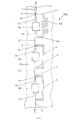
図1(a)〜図8(d)に示された本発明の実施の形態のマイクロ流体スイッチはすべて、少なくとも1つの第1流路3と、少なくとも1つの第2流路4とを有し、これらの流路は共通の端部領域6を有する。この共通の端部領域6には出口流路7が接続されている。
The microfluidic structure of the present invention will be described in detail with reference to the drawings.
All the microfluidic switches according to the embodiments of the present invention shown in FIGS. 1A to 8D have at least one
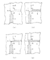
共通の端部領域6とこれに接続された流路3,4,7とは、図9(a)〜図9(c)に一例として一部が拡大されて示されている。これらの図面に基づいてまず本発明の基礎となる原理について説明する。
The
すでに述べたように端部領域6には第1流路3と第2流路4とが合流しており、一方、出口流路7は端部領域6から始まる。端部領域6では第1流路3に続いて毛細管停止部20が設けられている。ここで毛細管停止部20は幾何学的特性の急激な変化によって製作される。この種の毛細管停止部20は、第1流路3から流入する流体に対する障害を形成する。流体は毛細管停止部20に浸透するが、毛細管停止部20を越えて他の端部領域6へ入り込むためには流体は圧力差Δpを克服しなければならない。この圧力差Δpは次の数式により表される。
Δp=−2γcosΘ(1/w+1/h−1/W−1/H)
As already described, the
Δp = −2γcos Θ (1 / w + 1 / h−1 / W−1 / H)
ここで、wは毛細管停止部20を形成する流路の幅であり、hは毛細管停止部20を形成する流路の高さであり、Wは毛細管停止部20への接続部での残余の端部領域6の幅であり、Hは毛細管停止部20への接続部での残余の端部領域6の高さである。
Here, w is the width of the flow path that forms the
Θとγを介して材料係数、すなわち接触角と表面張力が計算に代入される(上記Hosokawaらの刊行物参照)。ここで流体の濡れ特性に依存して、急激に変化する幾何学的特性は大きな横断面から小さな横断面への、または小さな横断面から大きな横断面への変化により形成することができる。 Material coefficients, ie contact angle and surface tension, are substituted into the calculation via Θ and γ (see Hosokawa et al. Publication). Here, depending on the wetting characteristics of the fluid, a rapidly changing geometric characteristic can be formed by a change from a large cross section to a small cross section or from a small cross section to a large cross section.
毛細管停止部20で克服すべき圧力差Δpは、流体が第1流路3で流れることにより生じる搬送力に基づいては得ることができない。したがって毛細管停止部20は、克服すべき圧力差Δpに基づき、第1流路3内を流れる流体に対する障害となる。毛細管停止部20は次のようにして克服することができる。すなわち毛細管停止部20が他の共通の端部領域6の側から流体により濡れることにより克服することができる。この流体により毛細管停止部に発生する流体の表面張力が低下し、毛細管停止部20に滞留する流体は流出することができる。本発明では第2の流体が選択され、この第2の流体は毛細管停止部20の外から他の共通の端部領域に導かれる。この流体は毛細管停止部に滞留する流体と接触し、これにより第1の流体が再び流れ始める。したがって図1(a)〜図8(d)に示された実施形態では、毛細管停止部20の作用が第2流路4を介して案内された流体により解除される。
The pressure difference Δp to be overcome by the
第2流路4は、図9(c)に示すように共通の端部領域6と同じ深さと、これに続く出口流路7とを有する。これにより、第2流路4から共通の端部領域6への流体搬送の中断が阻止される。第2流路4がその端部前方で共通の端部領域6の高さよりも小さな高さを有する場合、端部領域6の高さは第2流路4の端部において構造的手段により達成できる。これはたとえば傾斜部、階段部、またはノッチであり、第2流路4の底部に端部領域6の底部のレベルで取り付けられる。この種のノッチはたとえば特許文献2に記載されている。これにより第2流路4での流れが共通の端部領域6へ移行する際に中断するのが阻止できる。
As shown in FIG. 9C, the
これに対して共通の端部領域6は第1流路に向かって突起を有する(図9(b)、図9(c))。共通の端部領域はこれにより第1流路3よりも大きな深さを有する。幾何学的形状のこの急激な変化により毛細管停止部が形成される。
In contrast, the
図10(a)〜図10(d)に詳細に示された、本発明の他の実施形態のスイッチは、図9(a)〜図9(c)に示されたスイッチとは異なり、第1流路3に対して先細の流路として第1流路3に接続する毛細管停止部20を有する。共通の端部領域6への移行部における先細の流路の端部が毛細管停止部である。さらなる相違点は、第2流路4と端部領域6との移行領域において袋状の溝があることである。その他の点ではこのスイッチは、図9(a)〜図9(c)に示したスイッチに相応する。
The switch of another embodiment of the present invention shown in detail in FIGS. 10 (a) to 10 (d) is different from the switch shown in FIGS. 9 (a) to 9 (c). The
図10(a)に示したように、流体流は第1流路3を介して毛細管停止部20に浸透し、毛細管停止部20と他の端部領域6との境界ですでに説明した表面張力のため停止する。第1流路3に対して直角または傾斜して端部領域6に合流する第2流路4を介して流体流は搬送力、たとえば毛管力に基づき端部領域6まで搬送される。この第2流路4を搬送される流体が端部領域6の拡張領域に達すると直ちに、流体は毛管力に基づいて毛細管停止部20が合流する端部領域6(図10(b))に流れる。流体が毛細管停止部20の流出開口部に達すると直ちに(図10(c))、流出開口部は外から濡れ、毛細管停止部20の作用は解除される。このとき第2流路4から流出する流体の前面が流体メニスカスに毛細管停止部20の合流領域で接触する。第2流路4と毛細管停止部20からの流体は接触し、毛細管停止部20の出口で克服しなければならない表面張力はこのことにより低下する。したがって第1流路3を介して導かれた流体は、第2流路4を介して導かれた流体と同じように端部領域6を完全に満たすことができ、そこから出口流路7を介してさらに導くことができる。
As shown in FIG. 10 (a), the fluid flow penetrates into the
したがって毛細管停止部20により形成された停止手段は第2流路4を介して導かれた流体により制御することができ、停止手段(毛細管停止部20)により中断された第1流路3の流体流を継続して進行させることができる。構造的手段により本発明のマイクロ流体スイッチでは、まず流体流が第1流路3を完全に満たし、それから第2流路4の流体流は時間的に遅れて、第1流路3の流体流の中断を消失させることができる。
Therefore, the stop means formed by the
図11に詳細に示した本発明のさらに他の実施の形態のスイッチは、図9(a)〜図9(c)または図10(a)〜図10(d)に示したスイッチとは異なり、内壁の表面特性が共通の端部領域6において、隣接する第1流路3に対して変化することにより毛細管停止部20が形成されている。第1流路3の内壁の表面は親水特性を有するのに対し、共通の端部領域では内壁の表面が疎水特性を有するように構成されている。表面特性が第1流路3から共通の端部領域6への移行の際に急激に変化することによって、毛細管停止部20が形成され、この毛細管停止部で第1流路3を介して導かれた流体前面が停止する。なぜなら搬送力が毛細管停止部20を克服するには十分でないからである。このように毛細管停止部20により形成された中断手段は、公知のようにして第2流路4を導かれた流体を介して制御することができ、第1流路3の流体の流体搬送を継続させることができる。
The switch of still another embodiment of the present invention shown in detail in FIG. 11 is different from the switch shown in FIG. 9 (a) to FIG. 9 (c) or FIG. 10 (a) to FIG. 10 (d). The
以下の記述に基づき本発明の種々のマイクロ流体スイッチをより詳細に説明する。ここでは種々の実施形態の相違についてより詳細に述べる。スイッチの個々の流路2,3,4,7はおおむね中空空間を有し、流路系として構成されているので、以下ではそのようなものとして称する。
The various microfluidic switches of the present invention will be described in more detail based on the following description. The differences between the various embodiments will now be described in more detail. Since the
以下では図1(a)および図1(b)を参照する。図1(a)および図1(b)に示された実施形態1は入口流路系2を有する。この入口流路系2は開始領域5に合流し、この開始領域で第1流路系3と第2流路系4とが始まる。第1流路系3は開始領域5に続いて流路状の第1区間3aを有する。この第1区間3aには第2区間3bが続いている。第2区間3bは中空空間として構成されており、この中空空間に化学物質、たとえば試薬を収納することができる。したがって第2区間3bは反応室を、第1実施形態1のマイクロ流体構成体において形成する。第1実施形態1の第2区間3bは、第1区間と同様に流路として構成された第3区間3cを介して端部領域6と、およびそこでとりわけ毛細管停止部20と接続されている。
In the following, reference is made to FIG. 1 (a) and FIG. 1 (b). The embodiment 1 shown in FIGS. 1A and 1B has an
開始領域5に続いて第2流路系4は、流路として構成された第1区間4aを有する。この第1区間には第2区間4bが続き、第2区間4bは中空空間として構成されており、これに第3区間4cが続く。第3区間は端部領域6に合流する。
Following the
図1(b)〜図1(d)に基づいて、第1実施形態1による本発明のスイッチの機能を説明する。ここで本発明のマイクロ流体スイッチは入口流路系2を介して満たされる。入口流路系2に流入した流体は入口流路系2での毛管力に基づき開始領域5へ搬送される。そこから流体流は分流し、このとき流路系3は流路系4よりも急速に流体により満たされる。第1流路系3では流体の一部により、第1区間3a、反応室として構成された第2区間3b、および第3区間3cが満たされる。第1流路系3の第3区間3cからは毛細管停止部20も、流体メニスカスが毛細管停止部20の端部で停止するまで満たされる。
The function of the switch of the present invention according to the first embodiment will be described with reference to FIGS. Here, the microfluidic switch according to the invention is filled via the
流体の別の部分は第2流路系4へ搬送される(図1(b)、図1(c))。ここではまず第1区間4aと次に第2区間4bを形成する中空空間が満たされる。続いて流体は作用する毛管力に基づき、第2流路系4の第3区間4cに流入し、時間的に遅れて端部領域6に達する。次にこの端部領域6で、すでに説明したように毛細管停止部20が解除される。第2流路系4から流出した流体によって毛細管停止部20が解除されるまでに経過した時間の間、第1流路系の第2区間3bの反応室に収納された試薬はこの第2区間3bに流入した流体と反応する。次に毛細管停止部20の解除により、流体は作用する毛管力に基づき反応室から流出するよう搬送され、出口流路7を介してマイクロ流体構成体から取り出すことができる。
Another part of the fluid is conveyed to the second flow path system 4 (FIG. 1B, FIG. 1C). Here, the hollow space forming
次に図2(a)〜図2(d)を参照し、第2実施形態11について説明する。第1実施形態1と同じように、第2実施形態11も入口流路系2を有する。ここで入口流路系2は、流路として構成された第1区間2aを有する。この第1区間2aには第2区間2bが続く。第2区間2bは中空空間により形成される。入口流路系の第3区間2cを介して第2区間2bは開始領域5と接続されており、この開始領域で第1流路系3と第2流路系4が始まる。第1流路系3も第2流路系4も第2実施形態11では簡単な流路により形成されている。第1流路系3と第2流路系4の流路の相応の構成によって、第1流路系3での流体搬送が第2流路系4におけるよりも格段に急速に行われるようにすることができる。2つの流路系3,4は共通の端部領域で合流し、このとき2つの流路系3,4を搬送される流体は端部領域6に配置された毛細管停止部20の後方で初めて合流することができる。
Next, a
マイクロ流体スイッチの第2実施形態11は入口流路系の第1区間2aを介して満たされる。流入した流体は作用する毛管力に基づいて、入口流路系の第2区間2bに搬送される。流体は入口流路系2の第3区間2cを介して第1流路系3と第2流路系4の共通の開始点5に搬送される。流体の一部は開始点5から第1流路系3へ搬送され、そこから作用する毛管力に基づいて毛細管停止部20へ浸透する。毛細管停止部20の端部で残りの終端点6に向かって流体は停止する。開始点5に達する流体の第2部分は第2流路系4の流路を通って端部領域6へ搬送される(図2(b)、図2(c))。第2流路系4で搬送される流体が端部領域6に達すると直ちに、毛細管停止部20は前記のようにして解除される。こうして流体を第1流路系3,第2流路系4および出口流路系7を介して排出することができる。ここでは流体の搬送は、作用する毛管力によって達成される。
The
本発明のマイクロ流体スイッチの第3実施形態12を図3(a)〜図3(c)に基づいて説明する。図3(a)〜図3(c)に示された第3実施形態12は、図1(a)〜図1(d)に示された第1実施形態とは、第2流路系4が種々の区間に分割されていない点で実質的に相違する。分割されるのではなく第2流路系4は1つの流路として開始領域5から端部領域6へ延びている。この流路の横断面は、第1流路系3の区間3aおよび区間3cにおける横断面よりも格段に小さく構成されている。
A
このことの利点は、中断手段(毛細管停止部20)の制御に必要な、第2流路系4で搬送される流体の容積が格段に小さいことである。したがって入口流路系2を介して流入する流体はほとんど完全に第1流路系3へ、したがって第2区間3bにより形成される反応室へ搬送される。マイクロ流体構成体12に流入する流体の大部分が第1流路系3へ搬送される。したがってこの流体の大部分を生成物に変換でき、この生成物が続いて端部領域6で第2流路系4を介して流入した流体量により希薄されることがない。
The advantage of this is that the volume of the fluid conveyed by the 2nd flow-
次に図4−1(a)を参照する。この図には本発明のマイクロ流体構成体13aが示されている。このマイクロ流体構成体13aは、第3実施形態12による3つのマイクロ流体スイッチの組合せに相当する。ここでは第3実施形態12によるマイクロ流体スイッチが相互に並列に配置されており、共通の供給流路8を介して流体が供給される。この共通の供給流路8から、3つ並列に接続された第3実施形態12による入口流路系2が分岐している。したがってマイクロ流体構成体13a全体は、第3実施形態12によるスイッチと供給流路8によって形成されている。その他の点で実施形態13aの各スイッチは第3実施形態12の個々のマイクロ流体スイッチと同じように機能する。
Reference is now made to FIG. This figure shows the
図4−2(b)に示されたマイクロ流体構成体13bは、第3実施形態12によるマイクロ流体スイッチを3つ有する。ここでマイクロ流体スイッチは相互に直列に接続されている。すなわち流体の搬送方向で第1スイッチの出口流路系7には第2スイッチの入口流路系2が接続され、第2スイッチの出口流路7には第3スイッチの入口流路系2が接続されている。ここで個々のスイッチは、図3(a)〜図3(c)に示された第3実施形態12のスイッチに相当する。図4−2(b)のマイクロ流体構成体の第3スイッチだけが第2流路系4の領域で異なって構成されている。この第2流路系4は、流体の搬送方向で順次接続された3つの区間を有する、ここで第1区間4aと第3区間4cとは単純な流路として構成されており、一方、中央の第2区間4bはメアンダ状に構成されている。第2区間4bをメアンダ状にすることにより、第3スイッチの第2流路系は第1および第2スイッチの第2流路系に対して延長される。このことにより、第3スイッチにおいて流体が第2流路系4から共通の端部領域6に達するまでの時間間隔が、マイクロ流体構成体13bの第1および第2スイッチの場合よりも大きくなる。その他の点でマイクロ流体構成体13bの個々のスイッチは第3実施形態12の個々後のスイッチと同じように機能する。
A microfluidic structure 13b shown in FIG. 4-2 (b) has three microfluidic switches according to the third embodiment. Here, the microfluidic switches are connected to each other in series. That is, the inlet
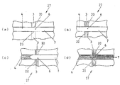
本発明のマイクロ流体スイッチの第4実施形態14が図5−1(a)〜図5−3(h)に示されている。ここで図5−3(f)、図5−3(g)および図5−3(h)は図5−1(a)、図5−1(c)および図5−2(e)の詳細を示す。
A
ここまで説明した実施形態とは異なり第4実施形態14では、第2流路系4が第1流路系3に対して鋭角に共通の端部領域6へ案内されている。さらなる相違点は、出口流路7が共通の端部領域から間隔をおいて第1分岐路7aおよび第2分岐路7bに分岐していることである。ここで第1分岐路7aは実質的に第1流路系3の断面積に相応する断面積を有する。これに対して第2分岐路は実質的に第2流路系4の断面積に相応する断面積を有する。
Unlike the embodiments described so far, in the
この第4実施形態において本発明のマイクロ流体構成体が基礎とする技術思想は、第1流路系3あるいは第2流路系4を介して導かれた流体は、共通の端部領域6に直接続く出口流路系7の領域でほとんど混合することなしに相互に重なり、層状となって第1分岐路7aおよび第2分岐路7bの分岐点まで流れ、ここで第1流路系3を介して供給された流体は第1分岐路7aへ排出され、第2流路系4を介して流入した流体は第2分岐路7bを介して排出されるということである。種々の流体の層流の特性はたとえば刊行物(独国特許第19536858号明細書)に記載されている。
In this fourth embodiment, the technical idea based on the microfluidic structure of the present invention is that the fluid guided through the first
生成物が反応室から第1流路系3へ、そしてそこから毛細管停止部20へ流入する場合、この生成物は毛細管停止部20により共通の端部領域6に留まる。生成物が第1流路系3あるいは毛細管停止部20に流入するのに時間的に遅れて、第2流体は第2流路系4を介して流入し(図5−1(c))、共通の端部領域6に入り込む(図5−1(d))。このとき第2流路系4から流入した流体は毛細管停止部20の流出開口部を濡らし、毛細管停止部20の機能を解除させる。次に毛細管停止部20と第1流路系3に滞留している生成物は作用する毛管力により端部領域あるいは出口流路系7へ搬送される。同時に流体は第2流路系4からも搬送される。2つの流体は近似的に平行に共通の端部領域へ流入し、乱流がないため層状に相互に重なる。そしてこの2つの流体は出口流路系7を介し並び合って搬送される。この搬送は分岐点で、生成物は実質的に第1分岐路7aを介して排出され、また第2流路系4を介して流入した流体は実質的に第2分岐路7bへ排出されるように行われる。
When the product flows from the reaction chamber into the first
第4実施形態14では、第2流路系4の容積が流路7bの容積に等しく、これにより第2流路系4を介して流入した流体が出口流路系7で完全に生成物から除去されるようにすると有利である。
In the
次に図6(a)〜図6(d)を参照する。図6(a)〜図6(d)に示された第5実施形態15では、第2流路系4を介して流入した流体が前もって生成物の出口流体から分流しない。これは第1,第2および第3実施形態の場合と同じである。第5実施形態15においては、第2流路系4は別個の流路系であり、共通の端部領域6に毛細管停止部20の後方で直接合流する。この種のマイクロ流体構成体はたとえば、第2流路系4を介して物質(試薬溶液)を別の生化学的反応のために導き、これを毛細管停止部20の解除後に、第1流路系3および毛細管停止部20を介して流入した生成物と共に別の反応室または分析室等に導く場合に適する。しかし生成物に影響を与えない不活性流体を第2流路系4へ毛細管停止部20の制御のために搬送することもできる。
Next, FIG. 6A to FIG. 6D will be referred to. In the
次に図7(a)〜図7(d)を参照する。多くの化学的および生化学的分析のためには、生成物を別の流体と混合し、新たな生成物を形成するための反応を引き起こすことが必要である。同じように生成物を別の分析のために希薄しなければならないこともある。このような処理のためには第6実施形態16によるマイクロ流体構成体が適する。この実施形態16では、第2流路系4を介して流入した流体が2つの別の流路系の切り替えに利用される。共通の端部領域6には第1流路系3と第2流路系4との他に、第3流路系17,18が合流する。この流路系は中空空間17と、中空空間17から共通の端部領域6に向かって案内された流路18を有する。中空空間17には外部から図示しない開口部を介して第2流体を満たすことができる。この流体は作用する毛管力に基づき流路18を介して共通の端部領域6へ搬送される。ここで流路18は、第1流路系3が共通の端部領域6へ毛細管停止部20として合流するのと同じように共通の端部領域で合流する。
Next, FIG. 7A to FIG. 7D will be referred to. For many chemical and biochemical analyses, it is necessary to mix the product with another fluid and trigger a reaction to form a new product. Similarly, the product may have to be diluted for another analysis. For such processing, the microfluidic structure according to the
第1流路系3および第3流路系17,18への流体搬送に時間的に遅延しないで、第2流路系4を介して流体が導かれる場合、第1流路系3の端部の毛細管停止部20の他に第3流路系17,18の端部の毛細管停止部20も、第2流路系4から流入した流体によって外から濡らされる。2つの毛細管停止部は解除され、共通の端部領域6およびこれに続く出口流路系7では種々異なる流体が出口流路系7を介して別の反応室または分析室19に搬送される。第2流路系4は共通の端部領域6ないし出口流路系7と同じ深さを有しているから、第2流路系4から流入した流体は妨げられずに共通の端部領域6へ流入することができ、これにより第1流路系3と第3流路系27,18に対する2つの毛細管停止部20を濡らし、毛細管停止部は解除される。
When the fluid is guided through the second
図8(a)〜図8(d)に基づいて、本発明のスイッチに対する第7実施形態27を説明する。この本発明のスイッチは2つの第1流路系3を有し、これらは共通の端部領域6に案内されている。ここで第1流路系3の合流部は毛細管停止部20として構成されており、これにより第1流路系に搬送された流体は毛細管停止部20で停止し、共通の端部領域6へは浸入しない。
Based on FIG. 8A to FIG. 8D, a
共通の端部領域ではさらに第2流路系4が合流する。第2流路系4で搬送される流体によって毛細管停止部20を流体により濡らすことができる。これにより毛細管停止部20は解除され、第1流路系3に導かれた流体は共通の端部領域6へ浸入する。次に出口流路系7によって、共通の端部領域6に存在する2つの第1流路系の流体と第2流路系4の流体とが共通の端部領域から排出される。
In the common end region, the second
2 入口流路
3 第1流路
4 第2流路
6 共通の端部領域
7 出口流路
20 毛細管停止部
2
Claims (18)
該スイッチは、少なくとも1つの第1流路と、少なくとも1つの第2流路とを有しており、
前記第1流路と前記第2流路とは、共通の開始領域を有しており、
前記第1流路と前記第2流路とは、1つの共通の端部領域を有しており、
前記第1流路は、前記共通の端部領域への移行部に、前記第1流路を流れる流体流を停止するための停止手段を有しており、
前記停止手段は、毛細管停止部であり、
前記共通の開始領域には、入口流路が前置接続されており、
前記共通の端部領域には、出口流路が後置接続されており、
前記入口流路に流入した流体流は、前記共通の開始領域から分流して、毛管力によって前記第1流路と前記第2流路とに入り、
前記第2流路で搬送される流体の容積は、前記第1流路で搬送される流体の容積よりも小さく、前記第1流路で搬送される流体量が、前記共通の端部領域で前記第2流路を介して流入した流体量によって希薄されることがなく、
前記第2流路を流れる流体流は、前記第2流路から前記共通の端部領域への流体搬送の中断なく流れ、
該停止手段は、前記第1流路だけに設けられ、
該停止手段は、前記第2流路を流れる流体流で前記停止手段を濡らすことによって、第1流路の流体流の搬送を制御可能であり、
前記第1流路で搬送される流体が前記停止手段に到達した後、前記第2流路で搬送される流体が前記共通の端部領域に到達するように、前記第2流路の流体が共通の端部領域まで前記第1流路の流体に対して時間的に遅延して搬送されることを特徴とするマイクロ流体スイッチ。 In a microfluidic switch for stopping fluid flow during a time interval,
The switch has at least one first flow path and at least one second flow path,
The first flow path and the second flow path have a common start area,
The first flow path and the second flow path have one common end region,
The first flow path has stop means for stopping the fluid flow flowing through the first flow path at the transition to the common end region,
The stopping means is a capillary stop;
An inlet channel is pre-connected to the common start region;
In the common end region, an outlet channel is post-connected,
The fluid flow that has flowed into the inlet channel is diverted from the common start region, and enters the first channel and the second channel by capillary force,
The volume of the fluid transported in the second flow path is smaller than the volume of the fluid transported in the first flow path, and the amount of fluid transported in the first flow path is in the common end region. Without being diluted by the amount of fluid flowing in through the second flow path,
The fluid flow through the second flow path flows without interruption of fluid conveyance from the second flow path to the common end region,
The stop means is provided only in the first flow path,
The stop means, by wetting the stop means in the fluid flow through said second flow path, Ri controllable der the conveyance of fluid flow of the first flow path,
After the fluid conveyed in the first flow path reaches the stopping means, the fluid in the second flow path reaches the common end region so that the fluid conveyed in the second flow path reaches the common end region. microfluidic switches, wherein Rukoto is conveyed by the delay time with respect to a common end fluid in the first flow path to the area.
第1流体を第1流路で停止手段まで搬送し、
前記第1流路で搬送される流体が前記停止手段に到達した後、前記第2流路で搬送される流体が前記共通の端部領域に到達するように、第2流体を第2流路で共通の端部領域まで前記第1流路の流体に対して時間的に遅延して搬送し、
前記停止手段を第2流体によって、前記第1流体が前記停止手段を越えてさらに搬送されるように制御することを特徴とするマイクロ流体スイッチの駆動方法。 A method of driving a microfluidic switch according to any one of claims 1-13,
Transport the first fluid to the stopping means in the first flow path;
After the fluid transported in the first flow path reaches the stopping means, the second fluid is passed through the second flow path so that the fluid transported in the second flow path reaches the common end region. Transported to the common end region at a time delay with respect to the fluid in the first flow path ,
The method of driving a microfluidic switch, characterized in that the stop means is controlled by a second fluid so that the first fluid is further conveyed beyond the stop means.
該スイッチは、少なくとも1つの第1流路と、少なくとも1つの第2流路とを有しており、The switch has at least one first flow path and at least one second flow path,
前記第1流路と前記第2流路とは、共通の開始領域を有しており、The first flow path and the second flow path have a common start area,
前記第1流路と前記第2流路とは、1つの共通の端部領域を有しており、The first flow path and the second flow path have one common end region,
前記第1流路は、前記共通の端部領域への移行部に、前記第1流路を流れる流体流を停止するための停止手段を有しており、The first flow path has stop means for stopping the fluid flow flowing through the first flow path at the transition to the common end region,
前記停止手段は、毛細管停止部であり、The stopping means is a capillary stop;
前記共通の開始領域には、入口流路が前置接続されており、An inlet channel is pre-connected to the common start region;
前記共通の端部領域には、出口流路が後置接続されており、In the common end region, an outlet channel is post-connected,
前記入口流路に流入した流体流は、前記共通の開始領域から分流して、毛管力によって前記第1流路と前記第2流路とに入り、The fluid flow that has flowed into the inlet channel is diverted from the common start region, and enters the first channel and the second channel by capillary force,
前記第2流路で搬送される流体の容積は、前記第1流路で搬送される流体の容積よりも小さく、The volume of the fluid conveyed in the second flow path is smaller than the volume of the fluid conveyed in the first flow path,
前記第2流路を流れる流体流は、前記第2流路から前記共通の端部領域への流体搬送の中断なく流れ、The fluid flow through the second flow path flows without interruption of fluid conveyance from the second flow path to the common end region,
該停止手段は、前記第1流路だけに設けられ、The stop means is provided only in the first flow path,
該停止手段は、前記第2流路を流れる流体流で前記停止手段を濡らすことによって、第1流路の流体流の搬送を制御可能であり、The stop means can control the conveyance of the fluid flow in the first flow path by wetting the stop means with the fluid flow flowing in the second flow path,
前記第1流路で搬送される流体が前記停止手段に到達した後、前記第2流路で搬送される流体が前記共通の端部領域に到達するように、前記第2流路の流体が共通の端部領域まで前記第1流路の流体に対して時間的に遅延して搬送されることを特徴とするマイクロ流体スイッチ。After the fluid conveyed in the first flow path reaches the stopping means, the fluid in the second flow path reaches the common end region so that the fluid conveyed in the second flow path reaches the common end region. A microfluidic switch, wherein the microfluidic switch is transported to the common end region with a time delay with respect to the fluid in the first flow path.
Applications Claiming Priority (2)
| Application Number | Priority Date | Filing Date | Title |
|---|---|---|---|
| DE10302720.3 | 2003-01-23 | ||
| DE2003102720 DE10302720A1 (en) | 2003-01-23 | 2003-01-23 | Microfluidic switch for stopping the flow of fluid during a time interval |
Publications (3)
| Publication Number | Publication Date |
|---|---|
| JP2004225912A JP2004225912A (en) | 2004-08-12 |
| JP2004225912A5 JP2004225912A5 (en) | 2007-04-19 |
| JP5164306B2 true JP5164306B2 (en) | 2013-03-21 |
Family
ID=32520085
Family Applications (1)
| Application Number | Title | Priority Date | Filing Date |
|---|---|---|---|
| JP2004016395A Expired - Fee Related JP5164306B2 (en) | 2003-01-23 | 2004-01-23 | Micro fluid switch |
Country Status (5)
| Country | Link |
|---|---|
| US (1) | US7134453B2 (en) |
| EP (1) | EP1441131B1 (en) |
| JP (1) | JP5164306B2 (en) |
| CN (1) | CN100531915C (en) |
| DE (1) | DE10302720A1 (en) |
Families Citing this family (69)
| Publication number | Priority date | Publication date | Assignee | Title |
|---|---|---|---|---|
| US7148257B2 (en) * | 2002-03-04 | 2006-12-12 | Merck Hdac Research, Llc | Methods of treating mesothelioma with suberoylanilide hydroxamic acid |
| US20050232821A1 (en) * | 2003-09-19 | 2005-10-20 | Carrillo Albert L | High density plate filler |
| US20070014694A1 (en) * | 2003-09-19 | 2007-01-18 | Beard Nigel P | High density plate filler |
| US7998435B2 (en) | 2003-09-19 | 2011-08-16 | Life Technologies Corporation | High density plate filler |
| US8277760B2 (en) | 2003-09-19 | 2012-10-02 | Applied Biosystems, Llc | High density plate filler |
| EP1525916A1 (en) * | 2003-10-23 | 2005-04-27 | F. Hoffmann-La Roche Ag | Flow triggering device |
| EP1525919A1 (en) * | 2003-10-23 | 2005-04-27 | F. Hoffmann-La Roche Ag | Flow triggering device |
| GB0327094D0 (en) * | 2003-11-21 | 2003-12-24 | Inverness Medical Switzerland | Laminated device |
| DE102004007567A1 (en) * | 2004-02-17 | 2005-09-01 | Boehringer Ingelheim Microparts Gmbh | Microstructured platform and method for handling a liquid |
| EP1827693B1 (en) * | 2004-12-09 | 2010-03-24 | Scandinavian Micro Biodevices ApS | A micro fluidic device and methods for producing a micro fluidic device |
| WO2006074665A2 (en) * | 2005-01-12 | 2006-07-20 | Inverness Medical Switzerland Gmbh | A method of producing a microfluidic device and microfluidic devices |
| DE502006009183D1 (en) * | 2005-01-27 | 2011-05-12 | Boehringer Ingelheim Micropart | Use of a device for examining sample liquid |
| WO2006090144A1 (en) * | 2005-02-25 | 2006-08-31 | Inverness Medical Switzerland Gmbh | Fluidic gating device |
| DE102005042601A1 (en) * | 2005-04-09 | 2006-10-12 | Boehringer Ingelheim Microparts Gmbh | Enzyme-linked immunosorbent assay (ELISA) process and assembly has a grid array of micro-dimension liquid holders and passages |
| DE102005016509A1 (en) * | 2005-04-09 | 2006-10-12 | Boehringer Ingelheim Microparts Gmbh | Apparatus for assaying a liquid sample comprises reaction chambers containing immobilized reagents, each connected to an assay chamber so that liquid can be transferred by centrifugal force |
| WO2006108559A2 (en) * | 2005-04-09 | 2006-10-19 | Boehringer Ingelheim Microparts Gmbh | Device and method for analyzing a sample liquid |
| DE102005016508A1 (en) * | 2005-04-09 | 2006-10-12 | Boehringer Ingelheim Microparts Gmbh | Apparatus for assaying a liquid sample comprises reaction chambers containing immobilized reagents, each connected to an assay chamber so that liquid can be transferred by centrifugal force |
| DE102005017653A1 (en) | 2005-04-15 | 2006-10-19 | Boehringer Ingelheim Microparts Gmbh | Device and method to control liquid flow has two sections of channel whereby liquid flows from one to the other and can be held at first section using capillary stop and said stop can be bypassed if wished by moving sections |
| EP1904232A2 (en) * | 2005-07-07 | 2008-04-02 | Inverness Medical Switzerland GmbH | A method of performing a test, a support instrument and a microliquid system comprising such support instrument |
| US7731910B2 (en) * | 2005-08-05 | 2010-06-08 | Hewlett-Packard Development Company, L.P. | Microfluidic mixing assembly |
| US20070113907A1 (en) * | 2005-11-18 | 2007-05-24 | Reid Brennen | Devices and methods using fluid-transporting features of differing dwell times |
| CN101400432B (en) * | 2006-03-09 | 2012-02-15 | 积水化学工业株式会社 | Micro fluid device and trace liquid diluting method |
| CN101173887B (en) * | 2006-11-02 | 2011-04-06 | 深圳迈瑞生物医疗电子股份有限公司 | Particle analyzer of sheath-flow impedance method |
| JP4852399B2 (en) * | 2006-11-22 | 2012-01-11 | 富士フイルム株式会社 | Two-component merger |
| US8877484B2 (en) * | 2007-01-10 | 2014-11-04 | Scandinavian Micro Biodevices Aps | Microfluidic device and a microfluidic system and a method of performing a test |
| WO2008113112A1 (en) * | 2007-03-16 | 2008-09-25 | Cleveland Biosensors Pty Ltd | Stop structure for microfluidic device |
| SE0700930L (en) * | 2007-04-16 | 2008-01-22 | Aamic Ab | Assay device for liquid samples |
| SE533515C2 (en) | 2008-04-16 | 2010-10-12 | Aamic Ab | Analysis procedure for simultaneous analysis of several analytes |
| US8063236B2 (en) * | 2008-05-08 | 2011-11-22 | University Of Florida Research Foundation, Inc. | Method for transferring N-atoms from metal complexes to organic and inorganic substrates |
| WO2010012281A1 (en) | 2008-07-29 | 2010-02-04 | Jacques Jonsmann | A microfluidic device |
| JP5665864B2 (en) * | 2009-07-07 | 2015-02-04 | ベーリンガー インゲルハイム マイクロパーツ ゲゼルシャフト ミットベシュレンクテル ハフツングBoehringer Ingelheim microParts GmbH | Plasma separation reservoir |
| EP2369343B1 (en) | 2010-03-15 | 2012-01-18 | Boehringer Ingelheim International Gmbh | Device and method for manipulating or examining a liquid sample |
| WO2011120773A1 (en) * | 2010-03-31 | 2011-10-06 | Boehringer Ingelheim Microparts Gmbh | Component of a biosensor and process for production |
| CN103154529B (en) * | 2010-09-14 | 2016-01-13 | 彭兴跃 | A kind of structure of microfluidic circuit chip series micro device |
| US9757723B2 (en) | 2010-10-08 | 2017-09-12 | Biomerieux, Inc. | Sample test cards |
| EP2486978A1 (en) | 2010-10-28 | 2012-08-15 | Roche Diagnostics GmbH | Microfluid test carrier for separating a fluid volume in partial volumes |
| WO2012056334A1 (en) * | 2010-10-28 | 2012-05-03 | International Business Machines Corporation | Microfluidic device with auxiliary and bypass channels |
| EP2455162A1 (en) | 2010-10-29 | 2012-05-23 | Roche Diagnostics GmbH | Microfluidic element for analysing a fluid sample |
| AU2011331974B2 (en) | 2010-11-23 | 2015-12-03 | Biomerieux, Inc. | Improved sample test cards |
| DE102011078770B4 (en) * | 2011-07-07 | 2016-04-28 | Robert Bosch Gmbh | Microfluidic device, microfluidic system and method of transporting fluids |
| JP2014525569A (en) | 2011-08-30 | 2014-09-29 | ザ・ロイヤル・インスティテューション・フォア・ザ・アドバンスメント・オブ・ラーニング/マクギル・ユニヴァーシティ | Method and system for a pre-programmed self-output microfluidic circuit |
| JP6162716B2 (en) | 2011-12-14 | 2017-07-12 | ウオーターズ・テクノロジーズ・コーポレイシヨン | Target frequency multipath length mixer |
| ITUD20120028A1 (en) * | 2012-02-21 | 2013-08-22 | Sedicidodici S R L | PERFUSION CHAMBER, RELATED EQUIPMENT USING THIS PERFUSION CHAMBER AND PROCEDURE FOR THE ANALYSIS OF THE THROMBOTIC-ISCHEMIC AND HEMORRHAGIC PATHOLOGY |
| PL398979A1 (en) * | 2012-04-25 | 2013-10-28 | Scope Fluidics Spólka Z Ograniczona Odpowiedzialnoscia | A microfluidic device and a microfluidic system comprising one or more microfluidic devices |
| WO2014019603A1 (en) | 2012-07-30 | 2014-02-06 | Nmi Naturwissenschaftliches Und Medizinisches Institut An Der Universitaet Tuebingen | Connector plate for a microfluidic sample chip, microfluidic sample chip and examination method using a microfluidic sample arrangement region |
| US9138746B2 (en) | 2013-05-01 | 2015-09-22 | Honeywell International Inc. | Fluid stop for measured sample containment |
| JP6360568B2 (en) * | 2014-06-16 | 2018-07-18 | コーニンクレッカ フィリップス エヌ ヴェKoninklijke Philips N.V. | Cartridge for rapid sample acquisition |
| EP3247675A4 (en) | 2015-01-23 | 2018-07-04 | Neofluidics LLC | A microfluidic serial dilution platform based well-plate using an oil-free immiscible phase driven by manual or electronic pipettors |
| DE102015204235B4 (en) * | 2015-03-10 | 2016-12-15 | Fraunhofer-Gesellschaft zur Förderung der angewandten Forschung e.V. | Fluidic structure with holding section and method for uniting two fluid volumes |
| DK3279310T3 (en) * | 2015-04-03 | 2021-08-02 | Aist | CELL CULTIVATION APPARATUS AND CELL CULTURE METHOD |
| EP3461559A1 (en) * | 2015-06-11 | 2019-04-03 | Neofluidics LLC | Manual or electronic pipette driven well plate for nano-liter droplet storage and methods of using same |
| WO2017001436A1 (en) * | 2015-06-29 | 2017-01-05 | Imec Vzw | Valve-less mixing method and mixing device |
| EP3615220A4 (en) * | 2017-04-28 | 2020-12-30 | Neofluidics, LLC | Fluidic devices with reaction wells and uses thereof |
| WO2018207006A1 (en) | 2017-05-12 | 2018-11-15 | Telefonaktiebolaget Lm Ericsson (Publ) | Local identifier locator network protocol (ilnp) breakout |
| US11441701B2 (en) | 2017-07-14 | 2022-09-13 | Hewlett-Packard Development Company, L.P. | Microfluidic valve |
| EP3665262A4 (en) | 2017-08-09 | 2021-09-01 | Neofluidics, LLC | Devices and methods for bioassay |
| US11185830B2 (en) | 2017-09-06 | 2021-11-30 | Waters Technologies Corporation | Fluid mixer |
| US11305279B2 (en) | 2017-11-10 | 2022-04-19 | Neofluidics, Llc | Integrated fluidic circuit and device for droplet manipulation and methods thereof |
| WO2020023942A2 (en) * | 2018-07-27 | 2020-01-30 | Terumo Bct Biotechnologies, Llc | Fluid flow-through |
| US11129061B1 (en) | 2018-11-07 | 2021-09-21 | Telefonaktiebolaget Lm Ericsson (Publ) | Local identifier locator network protocol (ILNP) breakout |
| WO2020232432A1 (en) * | 2019-05-16 | 2020-11-19 | Arris Enterprises Llc | Automated frequency coordination and device location awareness |
| US11555805B2 (en) | 2019-08-12 | 2023-01-17 | Waters Technologies Corporation | Mixer for chromatography system |
| EP3822634A1 (en) * | 2019-11-14 | 2021-05-19 | Apex Biotechnology Corporation | Biosensor strip and method thereof |
| WO2021161229A1 (en) * | 2020-02-12 | 2021-08-19 | University Of Canterbury | Microfluidic sealing valve and microfluidic circuit |
| US20230234051A1 (en) * | 2020-06-11 | 2023-07-27 | The Research Foundation For The State University Of New York | Microfluidic device and method |
| EP4217729A1 (en) | 2020-09-22 | 2023-08-02 | Waters Technologies Corporation | Continuous flow mixer |
| CN113117768A (en) * | 2021-04-09 | 2021-07-16 | 四川微康朴澜医疗科技有限责任公司 | Integration of micro-fluidic chip flow channel switching and reagent switching |
| WO2023021446A1 (en) * | 2021-08-18 | 2023-02-23 | University Of Canterbury | Microfluidic devices, systems and methods for providing an indication of rheology of a substance |
| WO2023213822A1 (en) * | 2022-05-02 | 2023-11-09 | Katholieke Universiteit Leuven | Dilution device |
Family Cites Families (16)
| Publication number | Priority date | Publication date | Assignee | Title |
|---|---|---|---|---|
| US4676274A (en) * | 1985-02-28 | 1987-06-30 | Brown James F | Capillary flow control |
| US5503985A (en) * | 1993-02-18 | 1996-04-02 | Cathey; Cheryl A. | Disposable device for diagnostic assays |
| DE19536858C2 (en) * | 1995-10-03 | 2000-04-13 | Danfoss As | Method and device for transporting a fluid through a channel |
| US20010055812A1 (en) * | 1995-12-05 | 2001-12-27 | Alec Mian | Devices and method for using centripetal acceleration to drive fluid movement in a microfluidics system with on-board informatics |
| US5942443A (en) * | 1996-06-28 | 1999-08-24 | Caliper Technologies Corporation | High throughput screening assay systems in microscale fluidic devices |
| US5800690A (en) * | 1996-07-03 | 1998-09-01 | Caliper Technologies Corporation | Variable control of electroosmotic and/or electrophoretic forces within a fluid-containing structure via electrical forces |
| US6090251A (en) * | 1997-06-06 | 2000-07-18 | Caliper Technologies, Inc. | Microfabricated structures for facilitating fluid introduction into microfluidic devices |
| DE59905743D1 (en) * | 1998-03-11 | 2003-07-03 | Steag Microparts Gmbh | SAMPLE CARRIER |
| US6601613B2 (en) * | 1998-10-13 | 2003-08-05 | Biomicro Systems, Inc. | Fluid circuit components based upon passive fluid dynamics |
| JP2002527250A (en) * | 1998-10-13 | 2002-08-27 | バイオマイクロ システムズ インコーポレイテッド | Fluid circuit components based on passive hydrodynamics |
| DE19859693A1 (en) * | 1998-12-23 | 2000-06-29 | Microparts Gmbh | Device for draining a liquid from capillaries |
| US6615856B2 (en) * | 2000-08-04 | 2003-09-09 | Biomicro Systems, Inc. | Remote valving for microfluidic flow control |
| AU2001281076A1 (en) * | 2000-08-07 | 2002-02-18 | Nanostream, Inc. | Fluidic mixer in microfluidic system |
| WO2002024320A1 (en) * | 2000-09-22 | 2002-03-28 | Kawamura Institute Of Chemical Research | Very small chemical device and flow rate adjusting method therefor |
| WO2002086333A1 (en) * | 2001-04-25 | 2002-10-31 | President And Fellows Of Harvard College | Fluidic switches and method for controlling flow in fluidic systems |
| US6725882B1 (en) * | 2003-01-03 | 2004-04-27 | Industrial Technology Research Institute | Configurable micro flowguide device |
-
2003
- 2003-01-23 DE DE2003102720 patent/DE10302720A1/en not_active Ceased
-
2004
- 2004-01-20 CN CNB2004100077974A patent/CN100531915C/en not_active Expired - Fee Related
- 2004-01-20 EP EP04001098.5A patent/EP1441131B1/en not_active Expired - Lifetime
- 2004-01-23 US US10/762,564 patent/US7134453B2/en active Active
- 2004-01-23 JP JP2004016395A patent/JP5164306B2/en not_active Expired - Fee Related
Also Published As
| Publication number | Publication date |
|---|---|
| DE10302720A1 (en) | 2004-08-05 |
| JP2004225912A (en) | 2004-08-12 |
| CN100531915C (en) | 2009-08-26 |
| US7134453B2 (en) | 2006-11-14 |
| CN1526479A (en) | 2004-09-08 |
| EP1441131B1 (en) | 2017-12-20 |
| EP1441131A1 (en) | 2004-07-28 |
| US20040206408A1 (en) | 2004-10-21 |
Similar Documents
| Publication | Publication Date | Title |
|---|---|---|
| JP5164306B2 (en) | Micro fluid switch | |
| US6901963B2 (en) | Micro fluidic device for controlling flow time of micro fluid | |
| US8084004B2 (en) | Microfluidic arrangement for metering of liquids | |
| KR100705361B1 (en) | A Capillary Flow Control Module and Lab-on-a-chip Equipped with the Same | |
| US11648555B2 (en) | Domino capillary microfluidic circuit | |
| JP2004225912A5 (en) | ||
| US9186638B2 (en) | Microfluidic structure | |
| US11590500B2 (en) | Microfluidic device, system, and method for reversing a flow through a microfluidic channel | |
| US10343161B2 (en) | Customizable microfluidic device with programmable microfluidic nodes | |
| AU2021254626A1 (en) | An arrangement for mixing fluids in a capillary driven fluidic system | |
| US9409171B2 (en) | Microfluidic structure having recesses | |
| JP7036746B2 (en) | Microfluidic chip | |
| JP2022080026A (en) | Dispenser in micro channel and micro channel device | |
| CN111841669A (en) | PCR chip for microorganism detection and liquid drop distribution method based on PCR chip | |
| KR100591244B1 (en) | Microfluidic device capable of controlling the pressure of the inlet and microfluidic network having the same | |
| JP2006078407A (en) | Method and apparatus for flow control, ink jet device, sampling apparatus | |
| CN115093962A (en) | Micro-fluidic chip based on flexible thin film and application of micro-fluidic chip in nucleic acid amplification |
Legal Events
| Date | Code | Title | Description |
|---|---|---|---|
| A521 | Request for written amendment filed |
Free format text: JAPANESE INTERMEDIATE CODE: A523 Effective date: 20070118 |
|
| A621 | Written request for application examination |
Free format text: JAPANESE INTERMEDIATE CODE: A621 Effective date: 20070118 |
|
| A521 | Request for written amendment filed |
Free format text: JAPANESE INTERMEDIATE CODE: A523 Effective date: 20070301 |
|
| A131 | Notification of reasons for refusal |
Free format text: JAPANESE INTERMEDIATE CODE: A131 Effective date: 20091110 |
|
| A601 | Written request for extension of time |
Free format text: JAPANESE INTERMEDIATE CODE: A601 Effective date: 20100204 |
|
| A602 | Written permission of extension of time |
Free format text: JAPANESE INTERMEDIATE CODE: A602 Effective date: 20100210 |
|
| A521 | Request for written amendment filed |
Free format text: JAPANESE INTERMEDIATE CODE: A523 Effective date: 20100510 |
|
| A02 | Decision of refusal |
Free format text: JAPANESE INTERMEDIATE CODE: A02 Effective date: 20100615 |
|
| A521 | Request for written amendment filed |
Free format text: JAPANESE INTERMEDIATE CODE: A523 Effective date: 20101015 |
|
| A911 | Transfer to examiner for re-examination before appeal (zenchi) |
Free format text: JAPANESE INTERMEDIATE CODE: A911 Effective date: 20110615 |
|
| A912 | Re-examination (zenchi) completed and case transferred to appeal board |
Free format text: JAPANESE INTERMEDIATE CODE: A912 Effective date: 20110715 |
|
| A601 | Written request for extension of time |
Free format text: JAPANESE INTERMEDIATE CODE: A601 Effective date: 20111129 |
|
| A602 | Written permission of extension of time |
Free format text: JAPANESE INTERMEDIATE CODE: A602 Effective date: 20111202 |
|
| A601 | Written request for extension of time |
Free format text: JAPANESE INTERMEDIATE CODE: A601 Effective date: 20120627 |
|
| A602 | Written permission of extension of time |
Free format text: JAPANESE INTERMEDIATE CODE: A602 Effective date: 20120702 |
|
| A521 | Request for written amendment filed |
Free format text: JAPANESE INTERMEDIATE CODE: A523 Effective date: 20120727 |
|
| A521 | Request for written amendment filed |
Free format text: JAPANESE INTERMEDIATE CODE: A523 Effective date: 20121101 |
|
| A61 | First payment of annual fees (during grant procedure) |
Free format text: JAPANESE INTERMEDIATE CODE: A61 Effective date: 20121218 |
|
| FPAY | Renewal fee payment (event date is renewal date of database) |
Free format text: PAYMENT UNTIL: 20151228 Year of fee payment: 3 |
|
| R150 | Certificate of patent or registration of utility model |
Ref document number: 5164306 Country of ref document: JP Free format text: JAPANESE INTERMEDIATE CODE: R150 Free format text: JAPANESE INTERMEDIATE CODE: R150 |
|
| R250 | Receipt of annual fees |
Free format text: JAPANESE INTERMEDIATE CODE: R250 |
|
| R250 | Receipt of annual fees |
Free format text: JAPANESE INTERMEDIATE CODE: R250 |
|
| R250 | Receipt of annual fees |
Free format text: JAPANESE INTERMEDIATE CODE: R250 |
|
| R250 | Receipt of annual fees |
Free format text: JAPANESE INTERMEDIATE CODE: R250 |
|
| R250 | Receipt of annual fees |
Free format text: JAPANESE INTERMEDIATE CODE: R250 |
|
| R250 | Receipt of annual fees |
Free format text: JAPANESE INTERMEDIATE CODE: R250 |
|
| R250 | Receipt of annual fees |
Free format text: JAPANESE INTERMEDIATE CODE: R250 |
|
| LAPS | Cancellation because of no payment of annual fees |