JP5164014B2 - Fuel cell system and control method thereof - Google Patents
Fuel cell system and control method thereof Download PDFInfo
- Publication number
- JP5164014B2 JP5164014B2 JP2006089023A JP2006089023A JP5164014B2 JP 5164014 B2 JP5164014 B2 JP 5164014B2 JP 2006089023 A JP2006089023 A JP 2006089023A JP 2006089023 A JP2006089023 A JP 2006089023A JP 5164014 B2 JP5164014 B2 JP 5164014B2
- Authority
- JP
- Japan
- Prior art keywords
- fuel cell
- hydrogen
- fuel
- gas supply
- gas
- Prior art date
- Legal status (The legal status is an assumption and is not a legal conclusion. Google has not performed a legal analysis and makes no representation as to the accuracy of the status listed.)
- Expired - Fee Related
Links
Images


Classifications
-
- H—ELECTRICITY
- H01—ELECTRIC ELEMENTS
- H01M—PROCESSES OR MEANS, e.g. BATTERIES, FOR THE DIRECT CONVERSION OF CHEMICAL ENERGY INTO ELECTRICAL ENERGY
- H01M8/00—Fuel cells; Manufacture thereof
- H01M8/04—Auxiliary arrangements, e.g. for control of pressure or for circulation of fluids
- H01M8/04298—Processes for controlling fuel cells or fuel cell systems
- H01M8/04694—Processes for controlling fuel cells or fuel cell systems characterised by variables to be controlled
- H01M8/04955—Shut-off or shut-down of fuel cells
-
- H—ELECTRICITY
- H01—ELECTRIC ELEMENTS
- H01M—PROCESSES OR MEANS, e.g. BATTERIES, FOR THE DIRECT CONVERSION OF CHEMICAL ENERGY INTO ELECTRICAL ENERGY
- H01M8/00—Fuel cells; Manufacture thereof
- H01M8/04—Auxiliary arrangements, e.g. for control of pressure or for circulation of fluids
- H01M8/04223—Auxiliary arrangements, e.g. for control of pressure or for circulation of fluids during start-up or shut-down; Depolarisation or activation, e.g. purging; Means for short-circuiting defective fuel cells
- H01M8/04228—Auxiliary arrangements, e.g. for control of pressure or for circulation of fluids during start-up or shut-down; Depolarisation or activation, e.g. purging; Means for short-circuiting defective fuel cells during shut-down
-
- H—ELECTRICITY
- H01—ELECTRIC ELEMENTS
- H01M—PROCESSES OR MEANS, e.g. BATTERIES, FOR THE DIRECT CONVERSION OF CHEMICAL ENERGY INTO ELECTRICAL ENERGY
- H01M8/00—Fuel cells; Manufacture thereof
- H01M8/04—Auxiliary arrangements, e.g. for control of pressure or for circulation of fluids
- H01M8/04223—Auxiliary arrangements, e.g. for control of pressure or for circulation of fluids during start-up or shut-down; Depolarisation or activation, e.g. purging; Means for short-circuiting defective fuel cells
- H01M8/04238—Depolarisation
-
- H—ELECTRICITY
- H01—ELECTRIC ELEMENTS
- H01M—PROCESSES OR MEANS, e.g. BATTERIES, FOR THE DIRECT CONVERSION OF CHEMICAL ENERGY INTO ELECTRICAL ENERGY
- H01M8/00—Fuel cells; Manufacture thereof
- H01M8/04—Auxiliary arrangements, e.g. for control of pressure or for circulation of fluids
- H01M8/04298—Processes for controlling fuel cells or fuel cell systems
- H01M8/043—Processes for controlling fuel cells or fuel cell systems applied during specific periods
- H01M8/04303—Processes for controlling fuel cells or fuel cell systems applied during specific periods applied during shut-down
-
- H—ELECTRICITY
- H01—ELECTRIC ELEMENTS
- H01M—PROCESSES OR MEANS, e.g. BATTERIES, FOR THE DIRECT CONVERSION OF CHEMICAL ENERGY INTO ELECTRICAL ENERGY
- H01M8/00—Fuel cells; Manufacture thereof
- H01M8/04—Auxiliary arrangements, e.g. for control of pressure or for circulation of fluids
- H01M8/04298—Processes for controlling fuel cells or fuel cell systems
- H01M8/04313—Processes for controlling fuel cells or fuel cell systems characterised by the detection or assessment of variables; characterised by the detection or assessment of failure or abnormal function
- H01M8/0438—Pressure; Ambient pressure; Flow
- H01M8/04388—Pressure; Ambient pressure; Flow of anode reactants at the inlet or inside the fuel cell
-
- H—ELECTRICITY
- H01—ELECTRIC ELEMENTS
- H01M—PROCESSES OR MEANS, e.g. BATTERIES, FOR THE DIRECT CONVERSION OF CHEMICAL ENERGY INTO ELECTRICAL ENERGY
- H01M8/00—Fuel cells; Manufacture thereof
- H01M8/04—Auxiliary arrangements, e.g. for control of pressure or for circulation of fluids
- H01M8/04298—Processes for controlling fuel cells or fuel cell systems
- H01M8/04313—Processes for controlling fuel cells or fuel cell systems characterised by the detection or assessment of variables; characterised by the detection or assessment of failure or abnormal function
- H01M8/0438—Pressure; Ambient pressure; Flow
- H01M8/04395—Pressure; Ambient pressure; Flow of cathode reactants at the inlet or inside the fuel cell
-
- H—ELECTRICITY
- H01—ELECTRIC ELEMENTS
- H01M—PROCESSES OR MEANS, e.g. BATTERIES, FOR THE DIRECT CONVERSION OF CHEMICAL ENERGY INTO ELECTRICAL ENERGY
- H01M8/00—Fuel cells; Manufacture thereof
- H01M8/04—Auxiliary arrangements, e.g. for control of pressure or for circulation of fluids
- H01M8/04298—Processes for controlling fuel cells or fuel cell systems
- H01M8/04313—Processes for controlling fuel cells or fuel cell systems characterised by the detection or assessment of variables; characterised by the detection or assessment of failure or abnormal function
- H01M8/04537—Electric variables
- H01M8/04544—Voltage
- H01M8/04559—Voltage of fuel cell stacks
-
- H—ELECTRICITY
- H01—ELECTRIC ELEMENTS
- H01M—PROCESSES OR MEANS, e.g. BATTERIES, FOR THE DIRECT CONVERSION OF CHEMICAL ENERGY INTO ELECTRICAL ENERGY
- H01M8/00—Fuel cells; Manufacture thereof
- H01M8/04—Auxiliary arrangements, e.g. for control of pressure or for circulation of fluids
- H01M8/04298—Processes for controlling fuel cells or fuel cell systems
- H01M8/04694—Processes for controlling fuel cells or fuel cell systems characterised by variables to be controlled
- H01M8/04746—Pressure; Flow
- H01M8/04753—Pressure; Flow of fuel cell reactants
-
- H—ELECTRICITY
- H01—ELECTRIC ELEMENTS
- H01M—PROCESSES OR MEANS, e.g. BATTERIES, FOR THE DIRECT CONVERSION OF CHEMICAL ENERGY INTO ELECTRICAL ENERGY
- H01M8/00—Fuel cells; Manufacture thereof
- H01M8/24—Grouping of fuel cells, e.g. stacking of fuel cells
- H01M8/241—Grouping of fuel cells, e.g. stacking of fuel cells with solid or matrix-supported electrolytes
-
- H—ELECTRICITY
- H01—ELECTRIC ELEMENTS
- H01M—PROCESSES OR MEANS, e.g. BATTERIES, FOR THE DIRECT CONVERSION OF CHEMICAL ENERGY INTO ELECTRICAL ENERGY
- H01M8/00—Fuel cells; Manufacture thereof
- H01M8/24—Grouping of fuel cells, e.g. stacking of fuel cells
- H01M8/2457—Grouping of fuel cells, e.g. stacking of fuel cells with both reactants being gaseous or vaporised
-
- H—ELECTRICITY
- H01—ELECTRIC ELEMENTS
- H01M—PROCESSES OR MEANS, e.g. BATTERIES, FOR THE DIRECT CONVERSION OF CHEMICAL ENERGY INTO ELECTRICAL ENERGY
- H01M8/00—Fuel cells; Manufacture thereof
- H01M8/10—Fuel cells with solid electrolytes
- H01M2008/1095—Fuel cells with polymeric electrolytes
-
- H—ELECTRICITY
- H01—ELECTRIC ELEMENTS
- H01M—PROCESSES OR MEANS, e.g. BATTERIES, FOR THE DIRECT CONVERSION OF CHEMICAL ENERGY INTO ELECTRICAL ENERGY
- H01M2250/00—Fuel cells for particular applications; Specific features of fuel cell system
- H01M2250/20—Fuel cells in motive systems, e.g. vehicle, ship, plane
-
- H—ELECTRICITY
- H01—ELECTRIC ELEMENTS
- H01M—PROCESSES OR MEANS, e.g. BATTERIES, FOR THE DIRECT CONVERSION OF CHEMICAL ENERGY INTO ELECTRICAL ENERGY
- H01M8/00—Fuel cells; Manufacture thereof
- H01M8/02—Details
- H01M8/0202—Collectors; Separators, e.g. bipolar separators; Interconnectors
- H01M8/023—Porous and characterised by the material
- H01M8/0234—Carbonaceous material
-
- H—ELECTRICITY
- H01—ELECTRIC ELEMENTS
- H01M—PROCESSES OR MEANS, e.g. BATTERIES, FOR THE DIRECT CONVERSION OF CHEMICAL ENERGY INTO ELECTRICAL ENERGY
- H01M8/00—Fuel cells; Manufacture thereof
- H01M8/04—Auxiliary arrangements, e.g. for control of pressure or for circulation of fluids
- H01M8/04298—Processes for controlling fuel cells or fuel cell systems
- H01M8/04313—Processes for controlling fuel cells or fuel cell systems characterised by the detection or assessment of variables; characterised by the detection or assessment of failure or abnormal function
- H01M8/0432—Temperature; Ambient temperature
- H01M8/04328—Temperature; Ambient temperature of anode reactants at the inlet or inside the fuel cell
-
- H—ELECTRICITY
- H01—ELECTRIC ELEMENTS
- H01M—PROCESSES OR MEANS, e.g. BATTERIES, FOR THE DIRECT CONVERSION OF CHEMICAL ENERGY INTO ELECTRICAL ENERGY
- H01M8/00—Fuel cells; Manufacture thereof
- H01M8/04—Auxiliary arrangements, e.g. for control of pressure or for circulation of fluids
- H01M8/04298—Processes for controlling fuel cells or fuel cell systems
- H01M8/04313—Processes for controlling fuel cells or fuel cell systems characterised by the detection or assessment of variables; characterised by the detection or assessment of failure or abnormal function
- H01M8/0432—Temperature; Ambient temperature
- H01M8/04335—Temperature; Ambient temperature of cathode reactants at the inlet or inside the fuel cell
-
- Y—GENERAL TAGGING OF NEW TECHNOLOGICAL DEVELOPMENTS; GENERAL TAGGING OF CROSS-SECTIONAL TECHNOLOGIES SPANNING OVER SEVERAL SECTIONS OF THE IPC; TECHNICAL SUBJECTS COVERED BY FORMER USPC CROSS-REFERENCE ART COLLECTIONS [XRACs] AND DIGESTS
- Y02—TECHNOLOGIES OR APPLICATIONS FOR MITIGATION OR ADAPTATION AGAINST CLIMATE CHANGE
- Y02E—REDUCTION OF GREENHOUSE GAS [GHG] EMISSIONS, RELATED TO ENERGY GENERATION, TRANSMISSION OR DISTRIBUTION
- Y02E60/00—Enabling technologies; Technologies with a potential or indirect contribution to GHG emissions mitigation
- Y02E60/30—Hydrogen technology
- Y02E60/50—Fuel cells
-
- Y—GENERAL TAGGING OF NEW TECHNOLOGICAL DEVELOPMENTS; GENERAL TAGGING OF CROSS-SECTIONAL TECHNOLOGIES SPANNING OVER SEVERAL SECTIONS OF THE IPC; TECHNICAL SUBJECTS COVERED BY FORMER USPC CROSS-REFERENCE ART COLLECTIONS [XRACs] AND DIGESTS
- Y02—TECHNOLOGIES OR APPLICATIONS FOR MITIGATION OR ADAPTATION AGAINST CLIMATE CHANGE
- Y02T—CLIMATE CHANGE MITIGATION TECHNOLOGIES RELATED TO TRANSPORTATION
- Y02T90/00—Enabling technologies or technologies with a potential or indirect contribution to GHG emissions mitigation
- Y02T90/40—Application of hydrogen technology to transportation, e.g. using fuel cells
Landscapes
- Life Sciences & Earth Sciences (AREA)
- Engineering & Computer Science (AREA)
- Manufacturing & Machinery (AREA)
- Sustainable Development (AREA)
- Sustainable Energy (AREA)
- Chemical & Material Sciences (AREA)
- Chemical Kinetics & Catalysis (AREA)
- Electrochemistry (AREA)
- General Chemical & Material Sciences (AREA)
- Fuel Cell (AREA)
Description
本発明は、燃料電池システムおよびその制御方法に関する。さらに詳述すると、本発明は、燃料電池システムの運転技術の改良に関する。 The present invention relates to a fuel cell system and a control method thereof. More specifically, the present invention relates to an improvement in operation technology of a fuel cell system.
従来、燃料電池システムを放置状態にしておく場合には、燃料電池の運転を停止させておく場合がある。また、燃料電池の発電効率が低い状態の時には当該燃料電池による発電を停止させることもある。そして、このようにシステムを放置状態にしている間においては、水素圧力が所定値以下になった場合に水素を供給するようにした技術が知られている(例えば、特許文献1参照)。
しかしながら、燃料電池システムを放置した状態にしておくと例えばカソード側触媒における担持カーボンが酸化されることがある。また、これによってセル電圧が恒常的に低下する等の発電性能の低下に至ることもある。さらには、過剰な水素が供給されてしまっている場合もある。 However, if the fuel cell system is left standing, for example, the supported carbon in the cathode side catalyst may be oxidized. Moreover, this may lead to a decrease in power generation performance such as a constant decrease in cell voltage. Furthermore, excessive hydrogen may have been supplied.
そこで、本発明は、システム放置時において、カソード側触媒における担持カーボンが酸化されて発電性能が低下するに至るのを抑制し、さらには過剰な水素の消費をも抑制できるようにした燃料電池システムおよびその制御方法を提供することを目的とする。 Therefore, the present invention suppresses the reduction in power generation performance due to oxidation of the supported carbon in the cathode side catalyst when the system is left standing, and further enables the suppression of excessive hydrogen consumption. And it aims at providing the control method.
かかる課題を解決するべく本発明者は種々の検討を行った。システムの運転停止中は、カソード出口側から空気が吸い込まれる等して燃料電池の内部に入り込み、当該空気がカソード側からアノード側へと拡散することがある。そうすると、当該空気中の酸素が電気化学反応に関わる結果、停止状態にあるにもかかわらず電圧が生じ(本明細書ではこれを異常電位という)、そのことが担持カーボンの酸化に関与する。本発明者は、このようなメカニズムによって発電性能の低下が引き起こされているものと考え、かかるメカニズムに着目してさらに検討を重ねた結果、先述の課題を解決しうる技術を知見するに至った。 In order to solve this problem, the present inventor has made various studies. While the system is stopped, air may be sucked into the fuel cell from the cathode outlet side, and the air may diffuse from the cathode side to the anode side. Then, as a result of oxygen in the air involved in the electrochemical reaction, a voltage is generated despite being in a stopped state (this is referred to as an abnormal potential in this specification), and this is involved in the oxidation of the supported carbon. The present inventor considers that such a mechanism is causing a decrease in power generation performance, and as a result of further investigation focusing on this mechanism, the inventors have come to know a technology that can solve the above-mentioned problems. .
本発明はかかる知見に基づくものであり、燃料電池に対する燃料ガス給排系および酸化ガス給排系における水素および酸素のモル量を算出する算出手段を有する燃料電池システムにおいて、前記燃料電池の停止時、前記燃料ガス中および前記酸化ガス中の化学反応可能な水素と酸素のモル比が2またはそれ以上になるように制御する制御手段を有することを特徴とするものである。 The present invention is based on such knowledge, and in the fuel cell system having calculation means for calculating the molar amounts of hydrogen and oxygen in the fuel gas supply / discharge system and the oxidizing gas supply / discharge system for the fuel cell, the fuel cell is stopped. And a control means for controlling the mole ratio of hydrogen and oxygen capable of chemical reaction in the fuel gas and in the oxidizing gas to be 2 or more.
上述のごとき検討から得られた知見からすれば、燃料電池中の担持カーボンが酸化してしまうのを極力防止するためには、必要時以外において水素と酸素が電気化学反応を起こすのを極力防止することが肝要だといえる。この点、水素と酸素とが燃料電池にて電気化学反応を起こすときの反応は、アノード側、カソード側ではそれぞれ
[化1]
2H2 → 4H++4e-
[化2]
O2+4H++4e- → 2H2O
であるから、燃料電池における全反応は
[化3]
2H2+O2 → 2H2O
と表すことができる。つまり、このような理論式に基づけば水素と酸素はモル比2:1の割合で反応するということになるから、これをひとつの目安とし、本発明では燃料ガス中および酸化ガス中の化学反応可能な水素と酸素のモル比が2またはそれ以上になるように制御する。こうした場合、化学反応可能な領域中では酸素よりも水素の方が潤沢に存在するいわば水素リッチな状態となるから、酸素が一定量を超えてまで消費されることはない状態を形成することができる。例えば、上記のモル比が一定値以上となるように水素を供給して水素の圧力(分圧)を高めるようにすれば通常状態よりも水素が潤沢な状態とすることができる。このように制御を行うようにした本発明によれば、水素リッチな条件にすることで電極触媒の酸化を抑制することができるとともに、運転停止時における水素と酸素のモル比を正確に計算して調節することで、過剰な水素の消費を抑制することができる。
Based on the knowledge obtained from the above-described studies, in order to prevent the supported carbon in the fuel cell from being oxidized as much as possible, it is possible to prevent hydrogen and oxygen from causing an electrochemical reaction when it is not necessary. It is important to do this. In this regard, the reaction when hydrogen and oxygen cause an electrochemical reaction in the fuel cell is different between the anode side and the cathode side.
[Chemical 1]
2H 2 → 4H + + 4e -
[Chemical 2]
O 2 + 4H + + 4e − → 2H 2 O
So the total reaction in the fuel cell is
[Chemical 3]
2H 2 + O 2 → 2H 2 O
It can be expressed as. In other words, hydrogen and oxygen react at a molar ratio of 2: 1 based on such a theoretical formula, and this is taken as a guideline. In the present invention, chemical reaction in fuel gas and oxidizing gas is performed. The possible hydrogen to oxygen molar ratio is controlled to be 2 or more. In such a case, hydrogen is more abundant than oxygen in the region where chemical reaction is possible, so that it becomes a hydrogen-rich state, so that a state where oxygen is not consumed beyond a certain amount may be formed. it can. For example, if the hydrogen pressure (partial pressure) is increased by supplying hydrogen so that the above molar ratio becomes a certain value or more, the hydrogen can be richer than the normal state. According to the present invention thus controlled, it is possible to suppress the oxidation of the electrode catalyst by setting it to a hydrogen-rich condition, and accurately calculate the molar ratio of hydrogen to oxygen at the time of shutdown. By adjusting the flow rate, excessive hydrogen consumption can be suppressed.
かかる燃料電池システムにおいては、前記燃料電池におけるセル電圧の大きさに応じ、前記モル比が維持されるように前記水素を供給することが好ましい。システム放置時に異常電位が生じないようにし、これによってカーボン酸化と恒常的な発電性能低下を抑制するというのが本発明の目的であるから、このように当該セルの電圧をモニタし、その大きさに応じて制御することは手段として好適である。また、本発明ではモル比を維持するために水素を供給し、水素が潤沢な状態とする。 In such a fuel cell system, it is preferable to supply the hydrogen so that the molar ratio is maintained according to the cell voltage of the fuel cell. Since it is an object of the present invention to prevent an abnormal potential from being generated when the system is left, thereby suppressing carbon oxidation and constant power generation performance degradation, the voltage of the cell is monitored in this way, and its magnitude is It is preferable as a means to control according to the above. In the present invention, hydrogen is supplied in order to maintain the molar ratio, and the hydrogen is in a rich state.
本発明において、前記算出手段は、前記燃料ガス給排系および前記酸化ガス給排系におけるガス流路の所定区間の容積と、前記水素または酸素の圧力とから算出するものである。この算出手段によれば、これらから燃料ガス給排系および酸化ガス給排系における水素および酸素のモル量を算出し、かかる算出結果に基づいて水素と酸素のモル比を制御することができる。 In the present invention, the calculation means calculates from a volume of a predetermined section of a gas flow path in the fuel gas supply / exhaust system and the oxidizing gas supply / exhaust system, and a pressure of the hydrogen or oxygen. According to this calculation means, the molar amounts of hydrogen and oxygen in the fuel gas supply / exhaust system and the oxidizing gas supply / exhaust system can be calculated from these, and the molar ratio of hydrogen and oxygen can be controlled based on the calculation result.
また、本発明にかかる燃料電池システムにおいて、前記酸化ガス給排系におけるガス流路に当該酸化ガスを前記ガス流路内に封止するための入口バルブおよび出口バルブが設けられていることが好ましい。さらに本発明では、前記燃料ガス給排系におけるガス流路に当該燃料ガスの供給バルブを設けることとしている。当該バルブを利用すれば、例えば酸化ガス給排系の出口側から酸化ガス(代表例として空気)が燃料電池へと流れ込むのを極力抑えることが可能となるから、当該酸化ガスがカソード側からアノード側へと拡散して酸素が電気化学反応に関わるのを抑えることができるようになる。これによれば、燃料電池の運転停止中(発電停止中)において異常電位が生じるのを抑制することが可能である。 In the fuel cell system according to the present invention, it is preferable that an inlet valve and an outlet valve for sealing the oxidizing gas in the gas channel are provided in the gas channel in the oxidizing gas supply / discharge system. . Furthermore, in the present invention, a supply valve for the fuel gas is provided in a gas flow path in the fuel gas supply / exhaust system. If the valve is used, for example, it is possible to suppress as much as possible the flow of the oxidizing gas (typically air) from the outlet side of the oxidizing gas supply / exhaust system to the fuel cell. It becomes possible to suppress oxygen from participating in the electrochemical reaction by diffusing to the side. According to this, it is possible to suppress the occurrence of an abnormal potential when the fuel cell is stopped (when power generation is stopped).
さらに、上述のごとくバルブが設けられている場合、前記算出手段は、前記バルブと前記燃料電池との間に位置する前記ガス流路の所定区間の容積と、前記水素または酸素の圧力とから算出するものとすることができる。当該バルブによってガスが所定の流路内に封止されている状態においては、既知の値(区切られた所定区間の容積)に基づいて水素および酸素のモル量を算出することができる。また、燃料電池からみて直近のバルブで区切られた区間を対象とすれば当該対象区間の容積が最小になるから、水素や酸素のモル量を比較的精度よく算出しうるという点で好ましい。 Further, when a valve is provided as described above, the calculation means calculates from the volume of a predetermined section of the gas flow path located between the valve and the fuel cell and the pressure of the hydrogen or oxygen. Can be. In a state where the gas is sealed in the predetermined flow path by the valve, the molar amounts of hydrogen and oxygen can be calculated based on a known value (volume of a predetermined predetermined section). Further, if the section divided by the valve closest to the fuel cell is targeted, the volume of the target section is minimized, which is preferable in that the molar amount of hydrogen or oxygen can be calculated with relatively high accuracy.
また、当該燃料電池の停止時間に応じて前記水素を供給することも好ましい。外部からの空気流入を完全に抑えでもしない限り酸素が電気化学反応を起こすのを完全に防止することは難しい。この点、当該停止時間をひとつのパラメータとして扱い、モル比が所定値以上となるように例えば定期的に制御することによって異常電位が生じるのを抑制することも可能である。 It is also preferable to supply the hydrogen according to the stop time of the fuel cell. Unless the inflow of air from the outside is completely suppressed, it is difficult to completely prevent oxygen from causing an electrochemical reaction. In this regard, it is also possible to suppress the occurrence of abnormal potential by treating the stop time as one parameter and periodically controlling the molar ratio to be equal to or greater than a predetermined value, for example.
さらに、本発明にかかる燃料電池システムの制御方法は、燃料電池に対する燃料ガス給排系および酸化ガス給排系における水素および酸素のモル量を算出し、当該燃料電池の停止時における前記燃料ガス中および前記酸化ガス中の化学反応可能な水素と酸素のモル比が2またはそれ以上になるように制御するというものである。 Furthermore, the fuel cell system control method according to the present invention calculates the molar amounts of hydrogen and oxygen in the fuel gas supply / exhaust system and the oxidizing gas supply / exhaust system for the fuel cell, and the fuel gas in the fuel gas when the fuel cell is stopped. And the molar ratio of hydrogen and oxygen capable of chemical reaction in the oxidizing gas is controlled to be 2 or more.
本発明によれば、システム放置時にカソード側触媒における担持カーボンが酸化されて発電性能が低下するに至るのを抑制することができるようになる。また、過剰な水素消費をも抑制することができる。 According to the present invention, it is possible to suppress a decrease in power generation performance due to oxidation of the supported carbon in the cathode side catalyst when the system is left standing. Moreover, excessive hydrogen consumption can also be suppressed.
以下、本発明の構成を図面に示す実施の形態の一例に基づいて詳細に説明する。 Hereinafter, the configuration of the present invention will be described in detail based on an example of an embodiment shown in the drawings.
図1〜図3に本発明にかかる燃料電池システムの実施形態を示す。本発明にかかる燃料電池システム1は、燃料電池2と、該燃料電池2に対する燃料ガス給排系および酸化ガス給排系と、これら燃料ガス給排系および酸化ガス給排系における水素および酸素のモル量を算出する算出手段と、燃料電池2の停止時、燃料ガス中および酸化ガス中の化学反応可能な水素と酸素のモル比が2またはそれ以上になるように制御する制御手段(以下、制御部ともいう)7と、を有しているものである。そして、これにより、システム放置時にカソード側触媒における担持カーボンが酸化されて発電性能が低下するに至る、という現象を抑制することとしている。
1 to 3 show an embodiment of a fuel cell system according to the present invention. A fuel cell system 1 according to the present invention includes a
以下においては、まず燃料電池システム1の全体構成について説明し、その後、担持カーボン酸化や発電性能低下を抑制するための上述のような構成について説明することとする。 In the following, the overall configuration of the fuel cell system 1 will be described first, and then the above-described configuration for suppressing supported carbon oxidation and power generation performance degradation will be described.
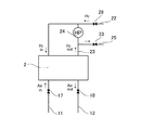
図1に本実施形態における燃料電池システム1の概略構成を示す。図示するように、燃料電池システム1は、燃料電池2と、酸化ガスとしての空気(酸素)を燃料電池2に供給する酸化ガス給排系(以下、酸化ガス配管系ともいう)3と、燃料ガスとしての水素を燃料電池2に供給する燃料ガス給排系(以下、燃料ガス配管系ともいう)4と、燃料電池2に冷媒を供給して燃料電池2を冷却する冷媒配管系5と、システムの電力を充放電する電力系6と、システム全体を統括制御する制御部7と、を備えている。
FIG. 1 shows a schematic configuration of a fuel cell system 1 in the present embodiment. As shown in the figure, a fuel cell system 1 includes a
燃料電池2は、例えば固体高分子電解質型で構成され、多数の単セルを積層したスタック構造を備えている。燃料電池2の単セルは、イオン交換膜からなる電解質の一方の面に空気極を有し、他方の面に燃料極を有し、さらに空気極及び燃料極を両側から挟みこむように一対のセパレータを有している。一方のセパレータの燃料ガス流路に燃料ガスが供給され、他方のセパレータの酸化ガス流路に酸化ガスが供給され、このガス供給により燃料電池2は電力を発生する。
The
酸化ガス配管系3は、燃料電池2に供給される酸化ガスが流れる供給路11と、燃料電池2から排出された酸化オフガスが流れる排出路12と、を有している。供給路11には、フィルタ13を介して酸化ガスを取り込むコンプレッサ14と、コンプレッサ14により圧送される酸化ガスを加湿する加湿器15と、が設けられている。排出路12を流れる酸化オフガスは、背圧調整弁16を通って加湿器15で水分交換に供された後、最終的に排ガスとしてシステム外の大気中に排気される。コンプレッサ14は、モータ14aの駆動により大気中の酸化ガスを取り込む。
The oxidizing
燃料ガス配管系4は、水素供給源21と、水素供給源21から燃料電池2に供給される水素ガスが流れる供給路22と、燃料電池2から排出された水素オフガス(燃料オフガス)を供給路22の合流点Aに戻すための循環路23と、循環路23内の水素オフガスを供給路22に圧送するポンプ24と、循環路23に分岐接続された排出路25と、を有している。
The fuel
水素供給源21は、例えば高圧タンクや水素吸蔵合金などで構成され、例えば35MPa又は70MPaの水素ガスを貯留可能に構成されている。水素供給源21の元弁26を開くと、供給路22に水素ガスが流出する。水素ガスは、調圧弁27その他の減圧弁により、最終的に例えば200kPa程度まで減圧されて、燃料電池2に供給される。
The
供給路22の合流点Aの上流側には、遮断弁28が設けられている。水素ガスの循環系は、供給路22の合流点Aの下流側流路と、燃料電池2のセパレータに形成される燃料ガス流路と、循環路23とを順番に連通することで構成されている。水素ポンプ24は、モータ24aの駆動により、循環系内の水素ガスを燃料電池2に循環供給する。
A
排出路25には、遮断弁であるパージ弁33が設けられている。パージ弁33が燃料電池システム1の稼動時に適宜開弁することで、水素オフガス中の不純物が水素オフガスと共に図示省略した水素希釈器に排出される。パージ弁33の開弁により、循環路23内の水素オフガス中の不純物の濃度が下がり、循環供給される水素オフガス中の水素濃度が上がる。
The
冷媒配管系5は、燃料電池2内の冷却流路に連通する冷媒流路41と、冷媒流路41に設けられた冷却ポンプ42と、燃料電池2から排出される冷媒を冷却するラジエータ43と、ラジエータ43をバイパスするバイパス流路44と、ラジエータ43及びバイパス流路44への冷却水の通流を設定する切替え弁45と、を有している。冷却ポンプ42は、モータ42aの駆動により、冷媒流路41内の冷媒を燃料電池2に循環供給する。
The
電力系6は、高圧DC/DCコンバータ61、バッテリ62、トラクションインバータ63、トラクションモータ64、及び各種の補機インバータ65,66,67を備えている。高圧DC/DCコンバータ61は、直流の電圧変換器であり、バッテリ62から入力された直流電圧を調整してトラクションインバータ63側に出力する機能と、燃料電池2又はトラクションモータ64から入力された直流電圧を調整してバッテリ62に出力する機能と、を有する。高圧DC/DCコンバータ61のこれらの機能により、バッテリ62の充放電が実現される。また、高圧DC/DCコンバータ61により、燃料電池2の出力電圧が制御される。
The
バッテリ62は、バッテリセルが積層されて一定の高電圧を端子電圧とし、図示しないバッテリーコンピュータの制御によって余剰電力を充電したり補助的に電力を供給したりすることが可能になっている。トラクションインバータ63は、直流電流を三相交流に変換し、トラクションモータ64に供給する。トラクションモータ64は、例えば三相交流モータであり、燃料電池システム1が搭載される例えば車両の主動力源を構成する。
The
補機インバータ65,66,67は、それぞれ、対応するモータ14a,24a,42aの駆動を制御する電動機制御装置である。補機インバータ65,66,67は、直流電流を三相交流に変換して、それぞれ、モータ14a,24a,42aに供給する。補機インバータ65,66,67は、例えばパルス幅変調方式のPWMインバータであり、制御部7からの制御指令に従って燃料電池2又はバッテリ62から出力される直流電圧を三相交流電圧に変換して、各モータ14a,24a,42aで発生する回転トルクを制御する。
The
制御部7は、内部にCPU,ROM,RAMを備えたマイクロコンピュータとして構成される。CPUは、制御プラグラムに従って所望の演算を実行して、後述するポンプ24の解凍制御など、種々の処理や制御を行う。ROMは、CPUで処理する制御プログラムや制御データを記憶する。RAMは、主として制御処理のための各種作業領域として使用される。制御部7は、ガス系統(3,4)や冷媒系統5に用いられる各種の圧力センサや温度センサ、外気温センサなどの検出信号を入力し、各構成要素に制御信号を出力する。
The control unit 7 is configured as a microcomputer including a CPU, a ROM, and a RAM inside. The CPU executes a desired calculation according to the control program, and performs various processes and controls such as a thawing control of the
続いて、本実施形態において、担持カーボン酸化や発電性能低下を抑制するための燃料電池システム1の構成ないしは機能について説明する(図2等参照)。 Subsequently, in the present embodiment, the configuration or function of the fuel cell system 1 for suppressing supported carbon oxidation and power generation performance degradation will be described (see FIG. 2 and the like).
上述したように、この燃料電池システム1は、システム放置時(燃料電池2の運転停止時)、カソード側触媒における担持カーボンが酸化されて発電性能が低下するに至る、という現象を抑制することとしている。そして、これを実現するために、燃料ガス配管系4および酸化ガス配管系3における水素および酸素のモル量を算出し、燃料電池2の停止時、燃料ガス中および酸化ガス中の化学反応可能な水素と酸素のモル比を制御することとしている。
As described above, the fuel cell system 1 suppresses the phenomenon that when the system is left (when the operation of the
燃料ガス配管系4および酸化ガス配管系3における水素および酸素のモル量を算出するための算出手段は、特に図示はしていないが、例えば、ガス圧力計、ガス分析計、温度センサ、水素センサなどによって構成される。また、計測された各パラメータ値に基づく計算は、例えば上述した制御部7で行うことができる。ちなみに、水素センサは水素に感応して光学的あるいは電気的物性変化を検出するもので、一般には半導体式、燃焼式、光学式、抵抗式のものが用いられる。
Calculation means for calculating the molar amounts of hydrogen and oxygen in the fuel
ここで、水素および酸素のモル量を算出する際の基本的な考え方について概略的に説明しておくと以下のとおりである。すなわち、例えば燃料ガス(水素)に関していえば、当該燃料ガスの圧力(分圧)をPH2、容積をVH2、温度をTH2、気体定数をRとすれば、状態方程式から、そのモル量nH2は
[化4]
nH2 = PH2VH2/RTH2
で求めることができる。同様に、酸化ガスに関していえば、当該酸化ガスの圧力(分圧)をPo2、容積をVo2、温度をTo2、気体定数をRとすれば、そのモル量no2は
[化5]
no2 = Po2Vo2/RTo2
で求めることができる。
Here, the basic concept for calculating the molar amounts of hydrogen and oxygen is roughly described as follows. That is, for example, regarding the fuel gas (hydrogen), if the pressure (partial pressure) of the fuel gas is P H2 , the volume is V H2 , the temperature is T H2 , and the gas constant is R, the molar amount is calculated from the equation of state. n H2 is
[Chemical 4]
n H2 = P H2 V H2 / RT H2
Can be obtained. Similarly, regarding the oxidizing gas, if the pressure (partial pressure) of the oxidizing gas is Po 2 , the volume is Vo 2 , the temperature is To 2 , and the gas constant is R, the molar amount no 2 is
[Chemical 5]
no 2 = Po 2 Vo 2 / RTo 2
Can be obtained.
なお、以上の基本的な考え方は上述したとおり理論式(状態方程式)に基づくものであり、実際に適用する場合には他の要素も考慮して適宜修正を加えることが好ましい。例えば、空気に含まれている水蒸気に関しては、当該状態下での水蒸気圧を考慮する一手段として飽和水蒸気圧をいわば近似値として扱うことができる。また、本実施形態では以上の理論式に基づいてモル比を2またはそれ以上に制御するが、これはしきい値(目標値)の最小の目安が2であるということであり、状況に応じて2を超える値を設定し、担持カーボンの酸化や発電性能の低下を十分に抑制するためのマージンをとるようにすることもできる。 Note that the basic concept described above is based on the theoretical formula (state equation) as described above, and when actually applied, it is preferable to appropriately modify in consideration of other factors. For example, regarding water vapor contained in air, saturated water vapor pressure can be treated as an approximate value as a means for considering the water vapor pressure under this condition. In the present embodiment, the molar ratio is controlled to 2 or more based on the above theoretical formula. This means that the minimum threshold (target value) is 2, which depends on the situation. Therefore, it is possible to set a value exceeding 2 to take a margin for sufficiently suppressing oxidation of the supported carbon and a decrease in power generation performance.
また、本実施形態では、燃料電池2におけるセル電圧の大きさに応じて燃料ガス(水素)を供給することとしている。そもそも、本実施形態においてはシステム放置時(燃料電池2の運転停止時)に異常電位が生じないようにし、これによって触媒のカーボン酸化と恒常的な発電性能低下を抑制することを目的にしているから、セルの電圧を実際にモニタし、その大きさに応じて燃料ガスを適宜供給することは異常電位を効果的に抑えることを可能にするという点で好ましい。また、単に燃料ガスを供給するような場合と比較して、セルの状況を踏まえて制御する本実施形態によれば燃料ガスの過剰な消費を抑制できるという点でも好ましい。
In the present embodiment, the fuel gas (hydrogen) is supplied in accordance with the magnitude of the cell voltage in the
さらに、本実施形態では、酸化ガス配管系3の供給路11およびに排出路12にそれぞれ入口バルブ17および出口バルブ18を設け、酸化ガスをガス流路内の所定区間に封止できるようにしている(図2参照)。これによれば、システム放置時、これらバルブ17,18にて区切られた燃料電池2側の所定区間内に酸化ガスを封止しておくことができるし、また、例えば酸化ガス配管系3の出口側(排出路12側)から酸化ガスが流れ込む(逆流する)のを極力抑えることもできるから、当該酸化ガスがカソード側からアノード側へと拡散して酸素が電気化学反応に関わるのを効果的に抑制することが可能である。
Further, in this embodiment, an
また、燃料ガス配管系4におけるガス流路には燃料ガスを供給するための供給バルブが設けられている。例えば本実施形態の場合であれば、上述した遮断弁28(さらには調圧弁27)をここでいう供給バルブとして用いている(図1、図2参照)。この場合であれば、当該供給バルブで区切られた燃料電池2側の所定区間の容積を化学式4におけるVH2としてモル量算出時に用いることができる。
The gas passage in the fuel
なお、図2に示しているように、本実施形態ではこれら入口バルブ17、出口バルブ18を燃料電池2に隣り合う位置に配置することとしている。この場合、さらに好ましくは、システム放置時において燃料ガスと酸化ガスとのモル比が2またはそれ以上となるようにこれら入口バルブ17、出口バルブ18を配置することである。例えば、入口バルブ17と出口バルブ18を燃料電池2の直近に配置すれば、酸化ガス側の所定区間容積がその分だけ小さくなるため、より大きな値のモル比にすることが可能となる。
As shown in FIG. 2, in this embodiment, the
ここまで説明した本実施形態の燃料電池システム1によれば、システム放置時、カソード側触媒における担持カーボンが酸化されて発電性能が低下するに至るのを抑制することが可能である(図3、図4参照。図中の電位差として示す1Vは一例)。すなわち、例えばカソード出口側から吸い込まれる等した酸化ガスが燃料電池2に入り込み、当該ガスがカソード側からアノード側へと拡散すると酸素が電気化学反応に関わり、システム放置時に異常電位が生じることがあるというのは先述のとおりだが(図4参照)、これに対し、本実施形態では、電気化学反応に供されるガスの存する領域内を水素リッチな状態とすることによって異常電位を抑制するようにしている(図3参照)。つまり、理論式に基づくモル比を目安とし、これを上回るように水素を供給することで、化学反応可能な領域中では酸素よりも水素の方が潤沢に存在するいわば水素リッチな状態を形成する。こうした場合、燃料電池2のアノード、カソードともに近傍に酸素がない(あるいは殆ど存在しない)状態とすることが可能となるから、化学反応が起こらないようにして異常電位を抑制することができる。この場合、状況に応じてはアノード、カソードとも水素雰囲気下にある状態となって両極が同電位となりうる。
According to the fuel cell system 1 of the present embodiment described so far, when the system is left standing, it is possible to suppress a decrease in power generation performance due to oxidation of the supported carbon in the cathode side catalyst (FIG. 3, See Fig. 4. 1V shown as potential difference in the figure is an example). That is, for example, when an oxidizing gas sucked from the cathode outlet side enters the
また、上述したように燃料ガス(水素)を供給することにより、システム停止状況下で水素圧力を高めることが可能であり、以下のような利点もある。すなわち、例えば本実施形態では酸化ガス配管系3に入口バルブ17、出口バルブ18を設けているが(図2参照)、仮にこれらバルブ17,18から酸化ガス(空気)が漏れ入ってくるようなおそれがある場合にも、このように水素圧力を高めた状態としておけば当該空気の漏れを抑制することが可能だし、仮に漏れ入ったとしても、カソード側からアノード側へと拡散して酸素が電気化学反応に関わるのを抑えることが可能である。したがって、例えばシステム放置状態が長時間にわたるような状況下においても、入口バルブ17や出口バルブ18における漏れ量をある程度まで許容することが可能となる。換言すれば、上記のような状態をも見込んで燃料ガス(水素)をやや多目に供給することも好ましい。
Further, by supplying the fuel gas (hydrogen) as described above, it is possible to increase the hydrogen pressure under the system stop condition, and there are the following advantages. That is, for example, in this embodiment, the oxidant
しかも、本実施形態の燃料電池システム1によれば、過剰な燃料ガス(水素)の消費を抑制することも可能だという利点がある。すなわち、燃料ガス(水素)を過剰に供給した場合、燃費が低下したり、再始動時におけるカソードからの排出水素量が増加したりしてしまうが、本実施形態の燃料電池1においては、セル電圧の大きさに応じてモル比が維持されるように水素供給を行うから過剰な消費を抑制することも可能である。 Moreover, according to the fuel cell system 1 of the present embodiment, there is an advantage that it is possible to suppress consumption of excess fuel gas (hydrogen). That is, when the fuel gas (hydrogen) is supplied excessively, the fuel consumption decreases or the amount of hydrogen discharged from the cathode at the time of restarting increases. However, in the fuel cell 1 of the present embodiment, the cell Since hydrogen is supplied so that the molar ratio is maintained according to the magnitude of the voltage, excessive consumption can be suppressed.
なお、上述の実施形態は本発明の好適な実施の一例ではあるがこれに限定されるものではなく本発明の要旨を逸脱しない範囲において種々変形実施可能である。例えば、上述した実施形態ではセル電圧をモニタし、その大きさに応じて燃料ガスを適宜供給するようにしたがこれは好適な一例に過ぎず、例えばセル電圧のモニタが難しい場合、あるいはシステム放置が長時間に及ぶような場合には、当該放置時間(燃料電池2の停止時間)に応じて水素を供給するという手段をとることも可能である。例示すれば、ある一定時間が経過するごとに一定量の水素を供給するといったものである。また、配管系にバルブ(入口バルブ17、出口バルブ18)等を備えていると外部からの空気流入を完全に抑えることが困難な場合があるが、このようにシステム停止時間をひとつのパラメータとして扱い、モル比が所定値以上となるように例えば定期的に制御することによって異常電位が生じるのを抑制することが可能である。また、水素を定期的に供給する場合にも当該水素の過剰な消費を抑えることが可能であるので燃費向上を図ることもできる。
The above-described embodiment is an example of a preferred embodiment of the present invention, but is not limited thereto, and various modifications can be made without departing from the scope of the present invention. For example, in the above-described embodiment, the cell voltage is monitored, and the fuel gas is appropriately supplied according to the magnitude thereof. However, this is only a preferable example. For example, when it is difficult to monitor the cell voltage or the system is left unattended. In such a case, it is possible to take a measure of supplying hydrogen according to the standing time (stopping time of the fuel cell 2). For example, a certain amount of hydrogen is supplied every certain time. Also, if the piping system is equipped with valves (
1…燃料電池システム、2…燃料電池、3…酸化ガス配管系(酸化ガス給排系)、4…燃料ガス配管系(燃料ガス給排系)、7…制御部(制御手段)、17…入口バルブ、18…出口バルブ、28…遮断弁(供給バルブ) DESCRIPTION OF SYMBOLS 1 ... Fuel cell system, 2 ... Fuel cell, 3 ... Oxidation gas piping system (oxidation gas supply / discharge system), 4 ... Fuel gas piping system (fuel gas supply / discharge system), 7 ... Control part (control means), 17 ... Inlet valve, 18 ... outlet valve, 28 ... shut-off valve (supply valve)
Claims (3)
前記酸化ガス給排系におけるガス流路内に酸化ガスを封止することを目的として、当該ガス流路のうち酸化ガス供給路側に設けられている入口バルブおよび酸化ガス排出路側に設けられている出口バルブと、
前記燃料ガス給排系のうち燃料ガス供給路側に設けられている当該燃料ガスの供給バルブと、
前記燃料電池の運転停止時、前記燃料ガス給排系における前記燃料ガスのうち当該燃料電池において化学反応可能な水素と、前記入口バルブおよび前記出口バルブによって封止された前記ガス流路内の酸化ガス中の化学反応可能な酸素とのモル比が最小目安の2またはそれ以上になるように制御する制御手段と、
前記燃料ガス給排系における化学反応可能な水素および前記酸化ガス給排系における化学反応可能な酸素のモル量を算出する算出手段と、
を有し、
前記燃料電池におけるセル電圧の大きさに応じて前記水素と酸素のモル比が最小目安の2またはそれ以上に維持されるように前記水素を供給し、前記燃料電池のアノードおよびカソードをともに水素雰囲気下にある状態とする
燃料電池システム。 In a fuel cell and a fuel cell system including a fuel gas supply / discharge system and an oxidant gas supply / discharge system for the fuel cell,
For the purpose of sealing the oxidant gas in the gas flow path in the oxidant gas supply / discharge system, the gas flow path is provided on the oxidant gas supply path side and the inlet valve provided on the oxidant gas supply path side. An outlet valve;
A fuel gas supply valve provided on the fuel gas supply path side of the fuel gas supply and discharge system;
When the fuel cell is stopped, hydrogen that can chemically react in the fuel cell in the fuel gas supply / exhaust system and oxidation in the gas flow path sealed by the inlet valve and the outlet valve Control means for controlling the molar ratio of the chemically reactive oxygen in the gas to a minimum standard of 2 or more;
A calculating means for calculating a molar amount of chemically reactive hydrogen in the fuel gas supply and discharge system and oxygen capable of chemical reaction in the oxidizing gas supply and discharge system;
Have
According to the cell voltage in the fuel cell, the hydrogen is supplied so that the molar ratio of hydrogen to oxygen is maintained at a minimum standard of 2 or more, and both the anode and the cathode of the fuel cell are in a hydrogen atmosphere. A fuel cell system in the state below .
Priority Applications (5)
| Application Number | Priority Date | Filing Date | Title |
|---|---|---|---|
| JP2006089023A JP5164014B2 (en) | 2006-03-28 | 2006-03-28 | Fuel cell system and control method thereof |
| CN200780011843XA CN101416339B (en) | 2006-03-28 | 2007-03-23 | Fuel cell system and control method thereof |
| PCT/JP2007/057002 WO2007116814A1 (en) | 2006-03-28 | 2007-03-23 | Fuel cell system and its control method |
| US12/293,466 US8916306B2 (en) | 2006-03-28 | 2007-03-23 | Fuel cell system and control method thereof |
| DE112007000681.1T DE112007000681B4 (en) | 2006-03-28 | 2007-03-23 | Control method for a fuel cell system |
Applications Claiming Priority (1)
| Application Number | Priority Date | Filing Date | Title |
|---|---|---|---|
| JP2006089023A JP5164014B2 (en) | 2006-03-28 | 2006-03-28 | Fuel cell system and control method thereof |
Publications (3)
| Publication Number | Publication Date |
|---|---|
| JP2007265786A JP2007265786A (en) | 2007-10-11 |
| JP2007265786A5 JP2007265786A5 (en) | 2009-04-30 |
| JP5164014B2 true JP5164014B2 (en) | 2013-03-13 |
Family
ID=38581108
Family Applications (1)
| Application Number | Title | Priority Date | Filing Date |
|---|---|---|---|
| JP2006089023A Expired - Fee Related JP5164014B2 (en) | 2006-03-28 | 2006-03-28 | Fuel cell system and control method thereof |
Country Status (5)
| Country | Link |
|---|---|
| US (1) | US8916306B2 (en) |
| JP (1) | JP5164014B2 (en) |
| CN (1) | CN101416339B (en) |
| DE (1) | DE112007000681B4 (en) |
| WO (1) | WO2007116814A1 (en) |
Families Citing this family (6)
| Publication number | Priority date | Publication date | Assignee | Title |
|---|---|---|---|---|
| JP5353558B2 (en) * | 2009-08-21 | 2013-11-27 | トヨタ自動車株式会社 | Fuel cell stack |
| US8232014B2 (en) * | 2009-12-11 | 2012-07-31 | GM Global Technology Operations LLC | Fuel cell operational methods for hydrogen addition after shutdown |
| JP5557579B2 (en) * | 2010-04-02 | 2014-07-23 | 本田技研工業株式会社 | Fuel cell system |
| JP5605106B2 (en) * | 2010-09-13 | 2014-10-15 | パナソニック株式会社 | Fuel cell power generator |
| WO2018020675A1 (en) * | 2016-07-29 | 2018-02-01 | 日産自動車株式会社 | Vehicle system |
| KR20210041971A (en) * | 2019-10-08 | 2021-04-16 | 현대자동차주식회사 | System for estimating purge amount of fuel cell, system and method for estimating hydrogen concentration using the same of fuel cell |
Family Cites Families (13)
| Publication number | Priority date | Publication date | Assignee | Title |
|---|---|---|---|---|
| JPH05251102A (en) | 1992-03-05 | 1993-09-28 | Toshiba Corp | Phospholic acid type fuel cell power generating plant |
| JPH09199151A (en) | 1996-01-12 | 1997-07-31 | Toshiba Corp | Fuel cell and its catalytic processing method |
| DE19953614A1 (en) * | 1999-11-08 | 2001-05-17 | Siemens Ag | Fuel cell system |
| US6399231B1 (en) * | 2000-06-22 | 2002-06-04 | Utc Fuel Cells, Llc | Method and apparatus for regenerating the performance of a PEM fuel cell |
| US6881508B2 (en) * | 2002-05-30 | 2005-04-19 | Plug Power, Inc. | Apparatus and method for controlling a fuel cell system |
| JP2004006166A (en) * | 2002-06-03 | 2004-01-08 | Fuji Electric Holdings Co Ltd | Solid polyelectrolyte type fuel cell and its operation method |
| JP2004158274A (en) * | 2002-11-06 | 2004-06-03 | Toyota Motor Corp | Moisture state estimation apparatus of fuel cell and fuel cell system |
| JP4182732B2 (en) * | 2002-11-22 | 2008-11-19 | トヨタ自動車株式会社 | FUEL CELL SYSTEM, MOBILE BODY MOUNTING THE SAME, AND METHOD FOR CONTROLLING FUEL CELL SYSTEM |
| JP4028363B2 (en) * | 2002-11-28 | 2007-12-26 | 本田技研工業株式会社 | Method for stopping power generation in fuel cell system |
| US7205058B2 (en) * | 2003-11-13 | 2007-04-17 | General Motors Corporation | Residual stack shutdown energy storage and usage for a fuel cell power system |
| JP4581382B2 (en) | 2003-11-27 | 2010-11-17 | 日産自動車株式会社 | Fuel cell system |
| JP4661055B2 (en) | 2004-02-03 | 2011-03-30 | パナソニック株式会社 | Fuel cell system and operation method |
| JP4629351B2 (en) | 2004-03-19 | 2011-02-09 | 株式会社日立製作所 | Polymer electrolyte fuel cell system |
-
2006
- 2006-03-28 JP JP2006089023A patent/JP5164014B2/en not_active Expired - Fee Related
-
2007
- 2007-03-23 CN CN200780011843XA patent/CN101416339B/en not_active Expired - Fee Related
- 2007-03-23 DE DE112007000681.1T patent/DE112007000681B4/en not_active Expired - Fee Related
- 2007-03-23 US US12/293,466 patent/US8916306B2/en active Active
- 2007-03-23 WO PCT/JP2007/057002 patent/WO2007116814A1/en active Search and Examination
Also Published As
| Publication number | Publication date |
|---|---|
| DE112007000681B4 (en) | 2015-01-15 |
| US8916306B2 (en) | 2014-12-23 |
| US20090092868A1 (en) | 2009-04-09 |
| CN101416339A (en) | 2009-04-22 |
| WO2007116814A1 (en) | 2007-10-18 |
| JP2007265786A (en) | 2007-10-11 |
| DE112007000681T5 (en) | 2009-02-12 |
| CN101416339B (en) | 2012-05-16 |
Similar Documents
| Publication | Publication Date | Title |
|---|---|---|
| JP5007927B2 (en) | Fuel cell system | |
| JP4868251B2 (en) | Fuel cell system, anode gas generation amount estimation device, and anode gas generation amount estimation method | |
| JP5120594B2 (en) | Fuel cell system and operation method thereof | |
| US8361667B2 (en) | Fuel cell system and its control method | |
| JP4993293B2 (en) | Fuel cell system and moving body | |
| JP5224082B2 (en) | Fuel cell system and drainage control method thereof | |
| US20100266920A1 (en) | Fuel cell system | |
| EP3070773B1 (en) | Fuel cell system | |
| JP5435320B2 (en) | FUEL CELL SYSTEM AND CONTROL METHOD FOR FUEL CELL SYSTEM | |
| JP5164014B2 (en) | Fuel cell system and control method thereof | |
| JP2008047353A (en) | Fuel cell system | |
| JP5229528B2 (en) | Fuel cell system | |
| WO2013105590A1 (en) | Fuel cell system | |
| JP2007141744A (en) | Fuel cell system | |
| JP2005032652A (en) | Fuel cell system | |
| JP5070794B2 (en) | Fuel cell system | |
| JP5077636B2 (en) | Fuel cell system | |
| JP2008084603A (en) | Fuel cell system and its purging method | |
| JP6304366B2 (en) | Fuel cell system | |
| JP5109280B2 (en) | Fuel cell system | |
| JP2006190571A (en) | Control device for fuel cell | |
| JP2005174757A (en) | Fuel cell system | |
| JP2015125911A (en) | Fuel cell system | |
| JP6287010B2 (en) | Fuel cell system | |
| JP2013164938A (en) | Fuel cell system and method for operating the same |
Legal Events
| Date | Code | Title | Description |
|---|---|---|---|
| A521 | Request for written amendment filed |
Free format text: JAPANESE INTERMEDIATE CODE: A523 Effective date: 20090317 |
|
| A621 | Written request for application examination |
Free format text: JAPANESE INTERMEDIATE CODE: A621 Effective date: 20090317 |
|
| A131 | Notification of reasons for refusal |
Free format text: JAPANESE INTERMEDIATE CODE: A131 Effective date: 20120326 |
|
| A521 | Request for written amendment filed |
Free format text: JAPANESE INTERMEDIATE CODE: A523 Effective date: 20120523 |
|
| TRDD | Decision of grant or rejection written | ||
| A01 | Written decision to grant a patent or to grant a registration (utility model) |
Free format text: JAPANESE INTERMEDIATE CODE: A01 Effective date: 20121126 |
|
| FPAY | Renewal fee payment (event date is renewal date of database) |
Free format text: PAYMENT UNTIL: 20151228 Year of fee payment: 3 |
|
| R151 | Written notification of patent or utility model registration |
Ref document number: 5164014 Country of ref document: JP Free format text: JAPANESE INTERMEDIATE CODE: R151 |
|
| A61 | First payment of annual fees (during grant procedure) |
Free format text: JAPANESE INTERMEDIATE CODE: A61 Effective date: 20121209 |
|
| FPAY | Renewal fee payment (event date is renewal date of database) |
Free format text: PAYMENT UNTIL: 20151228 Year of fee payment: 3 |
|
| LAPS | Cancellation because of no payment of annual fees |