JP5163051B2 - Game machine - Google Patents
Game machine Download PDFInfo
- Publication number
- JP5163051B2 JP5163051B2 JP2007275923A JP2007275923A JP5163051B2 JP 5163051 B2 JP5163051 B2 JP 5163051B2 JP 2007275923 A JP2007275923 A JP 2007275923A JP 2007275923 A JP2007275923 A JP 2007275923A JP 5163051 B2 JP5163051 B2 JP 5163051B2
- Authority
- JP
- Japan
- Prior art keywords
- symbol
- ball
- command
- display
- control device
- Prior art date
- Legal status (The legal status is an assumption and is not a legal conclusion. Google has not performed a legal analysis and makes no representation as to the accuracy of the status listed.)
- Active
Links
Images


Description
本発明は、パチンコ機等の遊技機に関するものである。 The present invention relates to a gaming machine such as a pachinko machine.
遊技機の一種としてパチンコ機がある。パチンコ機では、発射された遊技球が案内される遊技領域において、当該遊技球が入球可能な各種入球手段が設けられている。これら入球手段には、それぞれ遊技球の入球を検出する入球検出スイッチが設けられている。そして、入球検出スイッチから出力される検出信号が主制御装置に入力されると、主制御装置は、これらの検出信号に基づいて遊技に関する各種制御を行うこととなる。 One type of gaming machine is a pachinko machine. In the pachinko machine, in the game area where the launched game balls are guided, various entrance means for entering the game balls are provided. Each of these entrance means is provided with an entrance detection switch for detecting entrance of a game ball. And when the detection signal output from the entrance detection switch is input to the main control device, the main control device performs various controls relating to the game based on these detection signals .
上記入球検出スイッチとしては、例えば、近接スイッチやフォトスイッチなどの非接触式スイッチ、マイクロスイッチなどの接触式スイッチなどが採用されている(例えば、特許文献1参照)。
従来では、上述したどのようなタイプの入球検出スイッチであっても、一般的に遊技球の非検出中である通常時にはローレベル信号が出力され、遊技球の通過が検出されるとハイレベル信号が出力される。そして、主制御装置は、入球検出スイッチから出力される信号レベルが高くなった場合に割込み信号が入力されること等によって、当該入球検出スイッチに対応した入球手段に入球があったことを検出していた。 Conventionally, regardless of the type of entry detection switch described above, a low level signal is normally output during normal non-detection of a game ball, and a high level is detected when the passing of a game ball is detected. A signal is output. Then, the main control device has entered the entrance means corresponding to the entrance detection switch by receiving an interrupt signal when the signal level output from the entrance detection switch becomes high. It was detected.
ところが、上記構成の場合、入球検出スイッチから出力される信号にノイズが混入した場合などにおいて、入球があったと誤判断してしまうおそれがあった。 However, if the above-described configuration, in such as when noise is mixed in signals outputted from the ball entrance detection switch, there is a fear that misjudged that there is incoming balls.
本発明は、上記例示した問題点などを解決するためになされたものであり、その目的は、入球検出精度の向上を図ることのできる遊技機を提供することにある。 The present invention has been made to solve the above-described problems and the like, and an object of the present invention is to provide a gaming machine capable of improving the accuracy of detecting an incoming ball.
本発明に係る遊技機は、The gaming machine according to the present invention is
遊技球を発射する発射手段と、A launching means for launching a game ball;
発射された遊技球が案内される遊技領域と、A game area where the launched game ball is guided,
前記遊技領域内に配置された入球手段と、Entry means arranged in the game area;
前記入球手段へ入球した遊技球を検出する入球検出手段と、Entry detection means for detecting a game ball that has entered the entry means;
前記入球検出手段から出力される信号を監視して所定の制御を行う制御手段とを備えた遊技機において、In a gaming machine comprising control means for monitoring the signal output from the entrance detection means and performing predetermined control,
前記入球検出手段は、遊技球の非検出中はハイレベル信号を継続して出力し、遊技球の検出中はローレベル信号を継続して出力し、The entrance detection means continuously outputs a high level signal during non-detection of a game ball, and continuously outputs a low level signal during detection of a game ball,
前記制御手段は、The control means includes
前記入球検出手段から入力される信号レベルを定期的に監視する信号監視処理と、A signal monitoring process for periodically monitoring the signal level input from the entrance detection means;
前記信号レベルのレベル情報を、前記ハイレベル信号又は前記ローレベル信号に対応する2値の論理値で定期的に順次記憶していくレベル記憶処理と、Level storage processing in which the level information of the signal level is periodically and sequentially stored as binary logical values corresponding to the high level signal or the low level signal;
前記レベル記憶処理により記憶された少なくとも3回分以上のデータのうちの最先のデータの論理反転を行う論理反転処理と、Logical inversion processing for performing logical inversion of the earliest data among at least three times of data stored by the level storage processing;
前記論理反転されたデータとともに前記少なくとも3回分以上のデータのうちの他のデータすべての論理積を算出する論理積算出処理と、A logical product calculation process for calculating a logical product of all the other data of the at least three times of data together with the logically inverted data; and
前記論理積算出処理の演算結果に基づき、前記入球手段への入球の有無を判定する入球判定処理とを行うことをその要旨としている。The gist of the present invention is to perform a ball entry determination process for determining whether or not there is a ball entering the ball entry means based on the calculation result of the logical product calculation process.
本発明の遊技機によれば、入球検出精度の向上を図ることができる。According to the gaming machine of the present invention, it is possible to improve the accuracy of entering detection.
上述したように、遊技機の一種としてパチンコ機がある。パチンコ機では、発射された遊技球が案内される遊技領域において、当該遊技球が入球可能な各種入球手段が設けられている。これら入球手段には、それぞれ遊技球の入球を検出する入球検出スイッチが設けられている。そして、入球検出スイッチから出力される検出信号が主制御装置に入力されると、主制御装置は、これらの検出信号に基づいて遊技に関する各種制御を行うこととなる。As described above, there is a pachinko machine as a kind of gaming machine. In the pachinko machine, in the game area where the launched game balls are guided, various entrance means for entering the game balls are provided. Each of these entrance means is provided with an entrance detection switch for detecting entrance of a game ball. And when the detection signal output from the entrance detection switch is input to the main control device, the main control device performs various controls relating to the game based on these detection signals.
例えば、所定の入球手段に遊技球が入球した場合には、主制御装置は、検出結果に応じた払出指令を払出制御装置に送信する。これにより、所定の入球手段に対応した所定数の賞球が遊技者に対し払出される。For example, when a game ball enters a predetermined entrance means, the main control device transmits a payout command corresponding to the detection result to the payout control device. As a result, a predetermined number of prize balls corresponding to predetermined ball entry means are paid out to the player.
また、始動用の入球手段に遊技球が入球した場合には大当たり状態を発生させるか否かの当落抽選を行い、当選結果が得られると遊技者に有利な大当たり状態が発生する。大当たり状態が発生すると、遊技者は、大当たり用の入球手段に遊技球を入球させることにより、多くの賞球を獲得することができる。In addition, when a game ball enters the starting ball entry means, a winning lottery is performed to determine whether or not a big hit state is to be generated, and when a win result is obtained, a big hit state advantageous to the player is generated. When the big hit state occurs, the player can obtain a lot of prize balls by putting the game ball into the big hitting means.
さて、上記入球検出スイッチとしては、例えば、通過する遊技球の接触により作動片が動作してスイッチをオンオフすることで当該遊技球を検出する接触式のマイクロスイッチが一例に挙げられる。As an example of the entrance detection switch, for example, a contact-type microswitch that detects the game ball by operating the operating piece by turning on and off the switch by contact of the game ball passing therethrough can be cited.
この他、遊技球の通過に伴う磁束の変化を検出することにより当該遊技球の通過を検出する近接スイッチや、発光素子から受光素子へ向かう光が遊技球の通過により遮断されることで当該遊技球の通過を検出するフォトスイッチなどもある。In addition, a proximity switch that detects the passage of the game ball by detecting a change in magnetic flux accompanying the passage of the game ball, and light that travels from the light emitting element to the light receiving element is blocked by the passage of the game ball. There are also photo switches that detect the passage of a sphere.
近接スイッチやフォトスイッチなどの非接触式スイッチは、マイクロスイッチなどの接触式スイッチと比較して接触不良などの不具合が発生しにくく、耐久性などに優れているため、近年では数多く採用されている(例えば、特許文献1参照)。Non-contact type switches such as proximity switches and photo switches have been widely used in recent years because they are less prone to problems such as poor contact and superior durability compared to contact type switches such as micro switches. (For example, refer to Patent Document 1).
従来では、上述したどのようなタイプの入球検出スイッチであっても、一般的に遊技球の非検出中である通常時にはローレベル信号が出力され、遊技球の通過が検出されるとハイレベル信号が出力される。そして、主制御装置は、入球検出スイッチから出力される信号レベルが高くなった場合に割込み信号が入力されること等によって、当該入球検出スイッチに対応した入球手段に入球があったことを検出していた。Conventionally, regardless of the type of entry detection switch described above, a low level signal is normally output during normal non-detection of a game ball, and a high level is detected when the passing of a game ball is detected. A signal is output. Then, the main control device has entered the entrance means corresponding to the entrance detection switch by receiving an interrupt signal when the signal level output from the entrance detection switch becomes high. It was detected.
ところが、上記構成の場合、入球検出スイッチから出力される信号にノイズが混入した場合や、コネクタの抜き差し等を行い、ハイレベル信号を意図的に生成する不正行為が行われた場合などにおいて、これらの信号レベルの変化に基づき、入球があったと誤判断してしまうおそれがあった。However, in the case of the above configuration, in the case where noise is mixed in the signal output from the ball detection switch, or when a fraudulent act that intentionally generates a high level signal is performed by inserting or removing the connector, etc. Based on these changes in signal level, there was a risk of erroneously determining that there was a ball.
このようなことが起こると、実際には遊技球が入球手段へ入球していないにもかかわらず、賞球が払出されたり、当落抽選を行う契機が発生してしまうおそれがある。When this happens, there is a possibility that a prize ball will be paid out or a chance to win a lottery may occur even though the game ball has not actually entered the entry means.
本発明は、上記例示した問題点などを解決するためになされたものであり、その目的は、入球検出精度の向上を図ることのできる遊技機を提供することにある。The present invention has been made to solve the above-described problems and the like, and an object of the present invention is to provide a gaming machine capable of improving the accuracy of detecting an incoming ball.
以下、上記課題等を解決するのに適した各手段を項分けして説明する。なお、必要に応じて対応する手段に特有の作用効果等を付記する。 Hereinafter, each means suitable for solving the above-described problems will be described in terms of items. In addition, the effect etc. peculiar to a corresponding means are added as needed.
手段1.遊技球を発射する発射手段と、
発射された遊技球が案内される遊技領域と、
前記遊技領域内に配置された入球手段と、
前記入球手段へ入球した遊技球を検出する入球検出手段と、
前記入球検出手段から出力される信号を監視して所定の制御を行う制御手段とを備えた遊技機において、
前記入球検出手段は、遊技球の非検出中はハイレベル信号を継続して出力し、遊技球の検出中はローレベル信号を継続して出力し、
前記制御手段は、
前記入球検出手段から入力される信号レベルを定期的に監視する信号監視手段と、
前記信号レベルのレベル情報を、前記ハイレベル信号又は前記ローレベル信号に対応する2値の論理値で定期的に順次記憶していくレベル記憶手段と、
前記レベル記憶手段により記憶された少なくとも3回分以上のデータのうちの最先のデータの論理反転処理を行う論理反転手段と、
前記論理反転されたデータとともに前記3回分以上のデータのうちの他のデータすべての論理積を算出する論理積算出手段と、
前記論理積算出手段の演算結果に基づき、前記入球手段への入球の有無を判定する入球判定手段とを備えたことを特徴とする遊技機。
A game area where the launched game ball is guided,
Entry means arranged in the game area;
Entry detection means for detecting a game ball that has entered the entry means;
In a gaming machine comprising control means for monitoring the signal output from the entrance detection means and performing predetermined control,
The entrance detection means continuously outputs a high level signal during non-detection of a game ball, and continuously outputs a low level signal during detection of a game ball,
The control means includes
A signal monitoring means for periodically monitoring the signal level input from the entrance detection means;
Level storage means for periodically and sequentially storing the level information of the signal level as binary logical values corresponding to the high level signal or the low level signal;
Logic inversion means for performing logic inversion processing on the earliest data of at least three times of data stored by the level storage means;
Logical product calculating means for calculating the logical product of all other data of the three or more times of data together with the logically inverted data;
A gaming machine comprising: a ball entry judging means for judging whether or not there is a ball entering the ball entering means based on a calculation result of the logical product calculating means.
上記手段1によれば、レベル記憶手段を備え、ここに記憶されたレベル情報(例えば論理値「1」又は「0」)を基に所定の演算処理を行うことによりソフト的に入球判定処理を行うことができる。結果として、回路規模の大型化、ひいては生産コストの増大を抑制することができる。
According to the
仮にハイレベル信号に対応する論理値を「0」とし、ローレベル信号に対応する論理値を「1」とするとともに、過去3回分のデータを基に入球判定を行う構成とした場合において、例えばレベル記憶手段に記憶された最近の過去3回分の論理値が「0」,「1」,「1」である場合、最先(最古)のデータ「0」の論理反転処理を行うと、最先のデータは「1」となる。そして、このデータと他の2回分のデータの論理積は「1」となる。つまり、ここで論理積の値が「1」となった場合には、信号レベルがハイレベルからローレベルに切り替わったことを意味するため、これをもって入球判定手段は入球有りと判断することができる。 In the case where the logical value corresponding to the high level signal is set to “0”, the logical value corresponding to the low level signal is set to “1”, and the ball entering determination is performed based on the past three data, For example, when the logic values for the last three times stored in the level storage means are “0”, “1”, “1”, the logic inversion process of the earliest (oldest) data “0” is performed. The earliest data is “1”. The logical product of this data and the other two data is “1”. In other words, when the logical product value is “1” here, it means that the signal level has been switched from the high level to the low level, and therefore, the entrance determination means determines that there is an entrance. Can do.
このように、本手段1では、定期的に記憶された3回分以上のデータを基に判定処理を行うため、単に信号レベルの高低の違いを見るだけで、入球有無の判定を行う従来構成に比べて、ノイズや不正行為等に基づく信号レベル変化を正規な入球に基づくものと誤判断してしまうおそれを低減でき、入球検出精度の向上を図ることができる。 Thus, in this means 1, since the determination processing is performed based on the data stored three times or more periodically, the conventional configuration for determining the presence / absence of entering the ball simply by looking at the difference in signal level. In comparison with this, it is possible to reduce the possibility of erroneously determining that the signal level change based on noise, fraud or the like is based on a regular entry, and to improve the entry detection accuracy.
さらに、本手段1では、遊技球の非検出中にハイレベル信号が出力され、遊技球の検出中にローレベル信号が出力されるため、仮にノイズが混入してもハイレベル信号を維持することができ、従来のように遊技球の非検出中にローレベル信号が出力される構成に比べて、誤判断が下されにくくなる。 Furthermore, since the high level signal is output during non-detection of the game ball and the low level signal is output during detection of the game ball, this means 1 maintains the high level signal even if noise is mixed. This makes it difficult to make erroneous determinations as compared to the conventional configuration in which a low level signal is output during non-detection of a game ball.
なお、「制御手段」により行われる「所定の制御」としては、例えば、遊技球の払出制御、遊技者に有利な特別遊技状態を発生させるか否かの抽選制御、識別情報を変動表示する表示制御などが挙げられる。 The “predetermined control” performed by the “control means” includes, for example, game ball payout control, lottery control for determining whether or not a special game state advantageous to the player is generated, and display for variably displaying identification information For example, control.
手段2.前記ローレベル信号の継続期間が予め設定された規定期間を越えたか否かを判定することにより、前記規定期間を超えた場合には異常有りの判定を行う異常判定手段を備えたことを特徴とする手段1に記載の遊技機。
上述したようなパチンコ機等の遊技機においては、当該遊技機の僅かな隙間から「セル板」と称される薄板状部材や針金等の線状部材などを差し込み、その部材で入球検出手段をオンさせることで、あたかも入球手段へ遊技球が入球したかのように検出させるといった不正行為が行われるおそれがあった。 In a gaming machine such as a pachinko machine as described above, a thin plate member called a “cell plate” or a wire member such as a wire is inserted from a slight gap of the gaming machine, and the member detects the entrance. By turning on, there is a risk that an illegal act of causing the ball entry means to detect the game ball as if it had entered the ball may be performed.
実際に遊技球が入球手段へ入球してローレベル信号が出力された場合には、その出力時間(信号継続期間)は長くとも数msec〜10数msec程度である。これに対し、不正行為者がセル板等を挿し抜きするような人為的な動作は、入球手段へ入球した遊技球が入球検出手段を通過していく速度に比べて極めて遅く、どんなに短くとも数百msec程度かかってしまう。つまり、適正なローレベル信号の信号継続期間と同様の擬似的な信号を、セル板等の挿し抜きといった上記不正行為により生成することは、不可能である。特に遊技機の狭い隙間から内部にセル板等を差し込んで入球検出手段まで複雑な経路を通している場合には、なおさら困難である。 When a game ball actually enters the entrance means and a low level signal is output, the output time (signal duration) is at most about several milliseconds to several tens of milliseconds. On the other hand, an artificial action such as a fraudulent person inserting and removing a cell board etc. is extremely slow compared to the speed at which a game ball entering the entrance means passes through the entrance detection means. It takes about several hundred msec at the shortest. In other words, it is impossible to generate a pseudo signal similar to the signal duration of an appropriate low level signal by the above-mentioned fraudulent action such as insertion / removal of a cell plate or the like. In particular, it is even more difficult when a cell board or the like is inserted from a narrow gap of a gaming machine through a complicated route to the entrance detection means.
これに対し、上記手段2のように上記異常判定手段を備えれば、不正行為者の人為的な動作により生成される擬似的な信号を判別することができ、ひいては上記不正行為の抑制を図ることができる。
On the other hand, if the abnormality determination means is provided as in the
手段3.前記異常判定手段は、前記入球判定手段による判定の際に用いられるデータの数(レベル情報の数)よりも多くのデータを用いた前記論理反転手段及び前記論理積演算手段による演算結果に基づき、自身の判定を行うことを特徴とする手段2に記載の遊技機。
上記手段3によれば、入球判定手段及び異常判定手段の両手段が、同一の情報源に基づいて判定処理を行うことができ、構成の簡素化を図ることができる。さらに、ローレベル信号の継続期間等を計測するためのタイマ設定などを行う必要もない。
According to the
手段4.前記異常判定手段により異常有りと判定された場合において、その旨を報知する報知手段を備えたことを特徴とする手段2又は3に記載の遊技機。
上記手段4によれば、報知手段を備えることにより、異常有りと判定された場合には、その旨が報知される。これにより、入球検出手段に対し不正行為が行われているなど、何らかの異常が発生したことを遊技ホール関係者等が把握することができる。結果的に、不正行為などの早期発見に繋がる。なお、報知手段としては、ランプ等の発光手段、スピーカ等の音声発生手段、表示手段、ホールコンピュータ等の外部装置に対し信号を出力する外部端子基板等の外部出力手段などが挙げられる。 According to the above means 4, by providing the notifying means, when it is determined that there is an abnormality, the fact is notified. Thereby, a person concerned with a game hall or the like can know that some abnormality has occurred, such as an illegal act being performed on the incoming ball detecting means. As a result, it leads to early detection of fraud. Examples of the notification means include light emission means such as a lamp, sound generation means such as a speaker, display means, and an external output means such as an external terminal board that outputs a signal to an external device such as a hall computer.
手段5.前記異常判定手段により異常有りと判定された回数を記憶可能な異常回数記憶手段と、
前記異常有りと判定された回数が所定回数以上となった場合において、その旨を報知する報知手段とを備えたことを特徴とする手段2又は3に記載の遊技機。
Means 5. An abnormality number storage means capable of storing the number of times determined to be abnormal by the abnormality determination means;
4. A gaming machine according to means 2 or 3, further comprising a notifying means for notifying that when the number of times determined to be abnormal is not less than a predetermined number.
上記手段5によれば、上記手段4と同様の作用効果が奏される。異常有りが1回だけの場合には、不正行為でなく、単にノイズやコネクタの接触不良等による偶発的な不具合である可能性も考えられる。これに対し、異常有りが複数回あった場合には不正行為である可能性が高い。従って、上記手段5の構成とすることにより、偶発的な要因を極力排除し、不正行為の判断精度を高めることができる。
According to the means 5, the same effect as that of the
手段6.前記入球判定手段は、前記異常判定手段により前記ローレベル信号が異常有りと判定された場合には、当該ローレベル信号を無効とみなし、入球無しの判定を行うことを特徴とする手段2乃至5のいずれかに記載の遊技機。
Means 6. The
上記手段6によれば、異常有りの判定がなされた場合でも、正規の入球があった場合と同様の処理(例えば遊技球の払出し等)が行われてしまうといった不具合を防止することができる。 According to the means 6, even when it is determined that there is an abnormality, it is possible to prevent such a problem that the same processing (for example, paying out a game ball) as when there is a regular entry is performed. .
以下に、上記各手段が適用される各種遊技機の基本構成を示す。 The basic configuration of various gaming machines to which the above means are applied is shown below.
A.上記各手段における前記遊技機は弾球遊技機であること。より詳しい態様例としては、「遊技者が操作する操作手段(遊技球発射ハンドル)と、当該操作手段の操作に基づいて遊技球を弾いて発射する発射手段(発射モータ等)と、当該発射された遊技球が案内される遊技領域と、前記遊技領域内に配置された各入球手段(一般入賞口、可変入賞装置、作動口等)とを備えた弾球遊技機」が挙げられる。 A. The gaming machine in each of the above means is a ball game machine. As a more detailed mode example, “an operation means (game ball launching handle) operated by a player, a launching means (shot motor, etc.) for playing and launching a game ball based on an operation of the operation means, A ball ball game machine including a game area where a game ball is guided and each ball entry means (general prize opening, variable prize winning device, operation opening, etc.) arranged in the game area.
B.上記各手段における前記遊技機は略鉛直方向に延びる遊技領域を備えた弾球遊技機であること。より詳しい態様例としては、「遊技者が操作する操作手段(遊技球発射ハンドル)と、当該操作手段の操作に基づいて遊技球を弾いて発射する発射手段(発射モータ等)と、当該発射された遊技球が案内され、略鉛直方向に沿って延びる所定の遊技領域(例えば遊技領域は遊技盤面等により構成される)と、前記遊技領域内に配置された各入球手段(一般入賞口、可変入賞装置、作動口等)とを備え、前記遊技領域を流下する遊技球の挙動を視認可能に構成されてなる弾球遊技機」が挙げられる。 B. The gaming machine in each of the above means is a bullet ball gaming machine having a gaming area extending in a substantially vertical direction. As a more detailed mode example, “an operation means (game ball launching handle) operated by a player, a launching means (shot motor, etc.) for playing and launching a game ball based on an operation of the operation means, The game balls are guided and extended along a substantially vertical direction (for example, the game area is constituted by a game board surface), and each ball entry means (general winning mouth, And a ball game machine configured to be able to visually recognize the behavior of a game ball flowing down the game area.
C.上記各手段における前記遊技機、又は、上記各弾球遊技機は、パチンコ機又はパチンコ機に準ずる遊技機であること。 C. The gaming machine in each of the above means or each of the above ball game machines is a pachinko machine or a gaming machine equivalent to a pachinko machine.
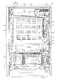
以下、パチンコ遊技機(以下、単に「パチンコ機」という)の一実施形態を、図面に基づいて詳細に説明する。ここで、図1はパチンコ機10の正面図であり、図2は斜視図であり、図3は内枠12及び前面枠セット14を開放した状態を示す斜視図である。図4は内枠12及び遊技盤30等の構成を示す正面図である。図5はパチンコ機10の背面図であり、図6は内枠12及び裏パックユニット203等を開放した状態を示す斜視図である。但し、図3では便宜上、遊技盤30面上に配設される釘や役物、前面枠セット14に取付けられるガラスユニット137等を省略して示している。
Hereinafter, an embodiment of a pachinko gaming machine (hereinafter simply referred to as “pachinko machine”) will be described in detail with reference to the drawings. Here, FIG. 1 is a front view of the
図3等に示すように、パチンコ機10は、当該パチンコ機10の外郭を構成する外枠11を備えており、この外枠11の一側部に内枠12が開閉可能に支持されている。
As shown in FIG. 3 and the like, the
外枠11は、図6等に示すように、上辺枠構成部11a及び下辺枠構成部11bが木製の板材により構成され、左辺枠構成部11c及び右辺枠構成部11dがアルミニウム合金製の押出成形材により構成され、これら各枠構成部11a〜11dがネジ等の離脱可能な締結具により全体として矩形枠状に組み付けられている。
As shown in FIG. 6 and the like, the
左辺枠構成部11cの上下端部には、それぞれ上ヒンジ81及び下ヒンジ82が取着されている(図1参照)。当該上ヒンジ81及び下ヒンジ82にて、内枠12の上下部が回動可能に支持されており、これにより内枠12が開閉可能となる。そして、外枠11の内側に形成される空間部に内枠12等が収容される。
An
また、右辺枠構成部11dには、その幅方向後端部近傍から外枠11内側へ向け突出した延出壁部83が形成されている。延出壁部83は、内枠12の右側部背面側に設けられる施錠装置600(図6参照)に対応する上下区間全域を内枠12の背面側から覆っている(図5参照)。加えて、図3に示すように、延出壁部83の前面側には、施錠装置600の係止部材が係止される上下一対の受部84,85が設けられている。また、下側の受部85には、後述する内枠開放検知スイッチ92に当接する押圧部86が、外枠11内側に向けて突設されている。
The right side
さらに、下辺枠構成部11bには樹脂製の幕板飾り87が取着されている。幕板飾り87の上面奥部には、上方に突出するリブ88が一体形成されている。これにより内枠12との間に隙間が形成されにくくなっている。
Furthermore, a
図3に示すように、内枠12の開閉軸線は、パチンコ機10の正面からみて左側において上下に沿って設定されており、この開閉軸線を軸心として内枠12が前方側に開放できるようになっている。内枠12は、外形が矩形状をなす樹脂ベース38を主体に構成されており、当該樹脂ベース38の中央部には略楕円形状の窓孔39が形成されている。
As shown in FIG. 3, the opening / closing axis of the
また、内枠12の前面側には前面枠セット14が開閉可能に取付けられている。前面枠セット14は、内枠12と同様に、パチンコ機10の正面から見て左側において上下に沿って設定された開閉軸線を軸心として前方側に開放できるようになっている。
A front frame set 14 is attached to the front side of the
前面枠セット14は、内枠12と同様に外形が矩形状をなし、閉鎖状態においては内枠12の前面側ほぼ全域を覆う。前面枠セット14の中央部には略楕円形状の窓部101が形成されている。これにより、前面枠セット14の窓部101及び内枠12の窓孔39を介して、内枠12の後面に装着される遊技盤30(遊技領域)を外部から視認可能となる。遊技盤30の詳細な構成については後述する。
The front frame set 14 has a rectangular outer shape like the
図1に示すように、前面枠セット14の前面側には、その下部中央において球受皿としての下皿15が設けられており、排出口16より排出された遊技球が下皿15内に貯留可能になっている。また、下皿15の手前側には、下皿15内から遊技球を排出するための球抜きレバー25が設けられている。
As shown in FIG. 1, on the front side of the front frame set 14, a
下皿15の右方には、手前側に突出した遊技球発射ハンドル(以下、単にハンドルという)18が設けられている。尚、ハンドル18には、図示しないタッチセンサや、ハンドル18の操作部の操作量を検出するための図示しない操作量検出手段が設けられている。
On the right side of the
下皿15の上方には上皿19が設けられている。上皿19は、遊技球を一旦貯留し、一列に整列させながら後述する発射手段としての遊技球発射装置(以下、単に発射装置という)70の方へ案内する球受皿である。なお、上皿19が遊技球で一杯になった状態では、払出される遊技球は下皿15へと案内される。
An
上皿19には球貸しボタン121と返却ボタン122とが設けられている。これにより、遊技ホール等において、パチンコ機10の側方に配置されるカードユニット(球貸しユニット)に紙幣やカード等を投入した状態で球貸しボタン121が操作されると、その操作に応じて貸出球が上皿19に供給される。一方、返却ボタン122は、カードユニットに挿入されたカード等の返却を求める際に操作される。但し、カードユニットを介さずに球貸し装置等から上皿19に遊技球が直接貸し出されるパチンコ機、いわゆる現金機では球貸しボタン121及び返却ボタン122は不要である。
The
また、前面枠セット14の前面にはその周囲に各種ランプ等の発光手段が設けられている。これら発光手段は、大当たり時や所定のリーチ時等における遊技状態の変化に応じて点灯、点滅といった発光態様が変更制御され遊技中の演出効果を高める役割を果たすものである。例えば、窓部101の周縁には、LED等の発光手段を内蔵した環状電飾部102が設けられている。また、該環状電飾部102の両側部には、所定のエラー時に点灯するエラー表示ランプ104が設けられている。尚、環状電飾部102のうち各エラー表示ランプ104の上方部位には、前面枠セット14の背面に設けられるスピーカSP(図3参照)に対応して細かな透孔が多数形成されている。
In addition, light emitting means such as various lamps are provided around the front surface of the front frame set 14. These light emitting means play a role of enhancing the effect of the game during the game by changing and controlling the light emission mode such as lighting and blinking according to the change of the game state at the time of big hit or predetermined reach. For example, at the periphery of the
前面枠セット14の背面側にはガラスユニット137が取付けられている。ガラスユニット137は、従来の前後一対の矩形状の板ガラスが前後対をなして別々に取着されるものではなく、全体として丸形をなし、アッセンブリ化された上で取付けられている。
A
次に、内枠12(樹脂ベース38)について図4を参照して説明する。上述した通り、内枠12(樹脂ベース38)には、窓孔39の後側において遊技盤30が装着されている。遊技盤30は、その周縁部が内枠12(樹脂ベース38)の裏側に当接した状態で取着されている。従って、遊技盤30の前面部の略中央部分が樹脂ベース38の窓孔39を通じて内枠12の前面側に露出した状態となっている。
Next, the inner frame 12 (resin base 38) will be described with reference to FIG. As described above, the
また、内枠12(樹脂ベース38)の前面下部、すなわち窓孔39(遊技盤30)の下方位置には、発射装置70及び当該発射装置70より発射された直後の遊技球を案内する発射レール61が取付けられている。本実施形態では、発射装置70としてソレノイド式発射装置を採用している。
Further, at the lower part of the front surface of the inner frame 12 (resin base 38), that is, below the window hole 39 (game board 30), a launch rail that guides the
次に、遊技盤30の構成について図4を参照して説明する。遊技盤30には、一般入賞口31、可変入賞装置32、第1契機対応ユニット(作動口)33、第2契機対応口34、可変表示装置ユニット35等がルータ加工によって形成された貫通孔に配設され、遊技盤30前面側から木ネジ等により取付けられている。周知の通り一般入賞口31、可変入賞装置32、第1契機対応ユニット33などの各種入賞口に遊技球が入球(入賞)すると、後述する各種検出スイッチにより検出され、上皿19(又は下皿15)へ所定数の賞球が払い出される。その他に、遊技盤30にはアウト口36が設けられており、一般入賞口31等の各種入賞口に入賞しなかった遊技球は、このアウト口36を通って遊技領域外へと排出される。また、遊技盤30には、遊技球の落下方向を適宜分散、調整等するために多数の釘が植設されているとともに、風車等の各種部材(役物)が配設されている。
Next, the configuration of the
第1契機対応ユニット33は、上入賞口33a及び下入賞口33bを備えるとともに、下入賞口33bに対応して一対の開閉部材33cを備えている。これにより、上入賞口33aが遊技球が常時入球可能な開状態となっているのに対し、下入賞口33bは、開閉部材33cが所定条件の成立に応じて開閉動作することにより、遊技球が入球不能な閉状態と、遊技球が入球可能な開状態とに切換わる。例えば、下入賞口33bは、通常モード時には開閉部材33cが開状態となり規定時間(例えば0.2秒)の経過した場合又は規定個数(例えば1個)の遊技球の入球があった場合に閉状態となる。この開閉処理は、通常モード時においては1回だけ行われる。また、上記構成に代えて、下入賞口33bが、遊技球が入球困難な閉状態と、遊技球が前記閉状態より入球容易な開状態とに切換わる構成としてもよい。
The first
可変表示装置ユニット35には、第2契機対応口34の通過をトリガとして変動表示する普通図柄表示装置41と、第1契機対応ユニット33(上入賞口33a又は下入賞口33b)への入賞をトリガとして変動表示する特別表示装置43と、特別表示装置43による変動表示に合わせて変動表示する装飾図柄表示装置42とが設けられている。
The variable
普通図柄表示装置41は、普通図柄として「○」又は「×」を点灯表示可能に構成されており、遊技球が第2契機対応口34を通過する毎に例えば普通図柄を「○」→「×」→「○」→・・・という具合に高速で切換表示(変動表示)する。そして、その変動表示が「○」図柄(当選図柄)で数秒間停止した場合には、第1契機対応ユニット33が所定時間だけ作動状態となる。この普通図柄表示装置41は、後述する主制御装置261によって直接的に表示内容が制御される。
The normal
また、普通図柄表示装置41の変動表示中に、新たに遊技球が第2契機対応口34を通過した場合には、その分の変動表示は、その時点で行われている変動表示の終了後に行われる構成となっている。つまり、変動表示が待機(保留)されることとなる。この保留される変動表示の最大回数は、パチンコ機の機種毎に決められているが、本実施形態では4回まで保留され、その保留回数が保留ランプ44にて点灯表示されるようになっている。
In addition, when the game ball newly passes through the second opportunity corresponding port 34 during the fluctuation display of the normal
特別表示装置43は、普通図柄表示装置41の右側方に設けられ、赤、緑、青の発光色を有する三色発光ダイオード(三色LED)により構成されている。そして、遊技球が第1契機対応ユニット33に入賞する毎に色換え表示(変動表示)が行われ、変動表示が停止したときの点灯態様(点灯色)により、大当たりか否かが確定的に表示される。
The
より詳しくは、第1契機対応ユニット33に対し遊技球が入賞すると、特別表示装置43は、3色LEDを赤→緑→青→赤→・・・という具合に高速で色換え表示(変動表示)し、所定時間が経過すると、いずれかの色に決定表示する。高速の色換え表示とは、例えば4msec毎に赤、緑、青を順番に表示するという具合である。大当たり抽選に当選した場合には、この際、赤又は緑で決定表示(例えば数秒間停止)され、特別遊技状態が発生する。特に、赤は、大当たり終了後の遊技モードが後述する高確率モードであることを示す表示であり、緑は、大当たり終了後の遊技モードが後述する時間短縮モードであることを示す表示である。なお、この特別表示装置43についても、主制御装置261によって表示内容が直接的に制御される。
More specifically, when the game ball wins the first
また、特別表示装置43の変動表示中に新たに遊技球が第1契機対応ユニット33に入賞した場合には、その分の変動表示は、その時点で行われている変動表示の終了後に行われる構成となっている。つまり、変動表示が待機(保留)されることとなる。この保留される変動表示の最大回数は、パチンコ機の機種毎に決められているが、本実施形態では4回まで保留され、その保留回数が保留ランプ46にて点灯表示されるようになっている。また、大当たり状態中に新たに遊技球が第1契機対応ユニット33に入賞した場合、その分の変動表示についても保留される。
Further, when a new game ball wins the first
装飾図柄表示装置42は液晶表示装置として構成されており、後述するサブ制御装置262及び表示制御装置45によって表示内容が制御される。すなわち、装飾図柄表示装置42においては、特別表示装置43にて表示される結果に対応させるように、主制御装置261からのコマンドに基づき、サブ制御装置262によって補助的な表示内容が決定され、表示制御装置45によって表示が行われる。装飾図柄表示装置42には、例えば、上、中及び下の3つの図柄列が表示される。各図柄列は複数の図柄によって構成されており、これら図柄が図柄列毎にスクロールされるようにして装飾図柄表示装置42に変動表示され、その後、上図柄列→下図柄列→中図柄列の順に停止表示される。また、可変表示装置ユニット35には、装飾図柄表示装置42を囲むようにしてセンターフレーム47が配設されている。
The decorative
可変入賞装置32は、通常は遊技球が入賞できない閉状態になっており、大当たり(特別遊技状態の発生)の際に、遊技球が入賞可能な開状態とされる。具体的には、規定時間(例えば29秒)の経過又は規定個数(例えば10個)の入賞を1ラウンド(特賞状態)として、可変入賞装置32の大入賞口が所定回数(所定ラウンド数)繰り返し開放される。
The
また、遊技盤30には、内レール構成部51と外レール構成部52とからなり、発射装置70から発射された遊技球を遊技盤30上部へ案内するレール50が取付けられている。これにより、ハンドル18の回動操作に伴い発射された遊技球は発射レール61及びレール50を通じて、遊技盤30とガラスユニット137との間に形成される遊技領域内に案内される。
The
内レール構成部51の先端部分(図4の左上部)には戻り球防止部材53が取着されている。これにより、一旦、レール50から遊技領域へと案内された遊技球が再度レール50内に戻ってしまうといった事態が防止される。
A return ball preventing member 53 is attached to the tip portion of the inner rail constituting portion 51 (the upper left portion in FIG. 4). This prevents a situation in which the game ball once guided from the
また、本実施形態では、外レール構成部52が遊技盤30の右上部で途絶え、内レール構成部51が遊技盤30の右下部で途絶えている。このため、遊技領域は、レール50及び樹脂ベース38の窓孔39の内周面により画定される。但し、内外レール構成部51,52の並行部分を除く。
In the present embodiment, the
図3に示すように、前面枠セット14の背面側には、窓部101の下方において、後述する払出機構部352から下皿15の排出口16へ繋がる球通路71が設けられている。また、内枠12に設けられた発射レール61とレールユニット50(外レール構成部52)との間には所定間隔の隙間があり、前面枠セット14の背面側には、前記隙間より落下した遊技球を下皿15へと案内するファール球通路72が形成されている。これにより、仮に、発射装置70から発射された遊技球が戻り球防止部材53まで至らずファール球としてレール50を逆戻りする場合には、そのファール球がファール球通路72を介して下皿15に排出される。
As shown in FIG. 3, on the back side of the front frame set 14, a
また、図3及び図4中の符号67は後述する払出機構部352により払出された遊技球を内枠12の前方に案内するための払出通路であり、上皿19に通じる通路と、球通路71ひいては下皿15に通じる通路とに分かれている。払出通路67の下方にはシャッタ68が設けられており、前面枠セット14を開放した状態では、バネ等の付勢力によりシャッタ68が前方に突出して払出通路67の出口をほぼ閉鎖するようになっている。また、前面枠セット14を閉じた状態では、球通路71の入口側後端部によってシャッタ68が押し開けられるようになっている。
3 and 4 is a payout passage for guiding a game ball paid out by a
次に、パチンコ機10の背面構成について図5、図6等を参照して説明する。パチンコ機10の背面には、各種制御基板が上下左右に並べられるようにして、一部前後に重ねられるようにして配置されており、さらに、遊技球を供給する遊技球供給装置(払出機構)や樹脂製の保護カバー等が取り付けられている。払出機構及び保護カバーは1ユニットとして一体化されており、一般に樹脂部分を裏パックと称することもあるため、ここではそのユニットを「裏パックユニット203」と称する。
Next, the back configuration of the
まず、遊技盤30の背面構成について説明する。図6に示すように、遊技盤30中央の貫通孔に対応して配設された可変表示装置ユニット35(図4参照)の背面側には、センターフレーム47を背後から覆う樹脂製のフレームカバー213が後方に突出して設けられている。また、フレームカバー213の背面側には、フレームカバー213の開口部から前方に臨む液晶表示装置たる装飾図柄表示装置42、表示制御装置45及びサブ制御装置262が前後に重ねられた状態で着脱可能に取り付けられている。
First, the back configuration of the
装飾図柄表示装置42は、当該装飾図柄表示装置42の表示部(液晶画面)をパチンコ機10の前面側に露出させるための開口部が形成された収容ボックス42aに収容されてフレームカバー213の背面側に固定されている。表示制御装置45は基板ボックス45aに収容されて装飾図柄表示装置42(収容ボックス42a)の背面側に固定されている。サブ制御装置262は基板ボックス262aに収容されて表示制御装置45(基板ボックス45a)の背面側に固定されている。尚、フレームカバー213内には、センターフレーム47に内蔵されたLED等を駆動するLED制御基板等が配設されている。また、収容ボックス42a及び基板ボックス45a,262aは透明樹脂材料等により構成され、内部が視認可能となっている。
The decorative
フレームカバー213の下方には裏枠セット215が、一般入賞口31、可変入賞装置32及び第1契機対応ユニット33等を背後から覆うようにして遊技盤30に取付けられている。裏枠セット215は、各種入賞口に入賞した遊技球を回収するための球回収機構を備えている(図示略)。この球回収機構により回収された遊技球は、後述する排出通路部217に案内され、排出通路部217の排出シュートからパチンコ機10外部に排出される。
Under the
また、本実施形態では、裏枠セット215が主制御装置261の取付台として機能する。より詳しくは、主制御装置261を搭載した基板搭載ユニット701が、裏枠セット215に対し回動可能に軸支され、後方に開放可能となっている。
In the present embodiment, the back frame set 215 functions as a mounting base for the
主制御装置261は透明樹脂材料等よりなる基板ボックス263に収容されている。基板ボックス263は、ボックスベースと該ボックスベースの開口部を覆うボックスカバーとを備え、これらボックスベースとボックスカバーとが封印部材によって連結されている。封印部材によって連結された基板ボックス263は、所定の痕跡を残さなければ開封できない構成となっている。これにより、基板ボックス263が不正に開封された旨を容易に発見することができる。
The
また、遊技盤30には、入球手段としての一般入賞口31等の各種入賞口に対応して、当該各種入賞口へ入球した遊技球を検出する入球検出スイッチ(入球検出手段)が設けられている。具体的には、図4に示すように、一般入賞口31に対応する位置には入賞口スイッチ221が設けられ、可変入賞装置32にはカウントスイッチ223が設けられている。また、第1契機対応ユニット33には、上入賞口33a及び下入賞口33bそれぞれに対応して第1契機対応ユニットスイッチ224a,224bが設けられている。さらに、第2契機対応口34に対応する位置には第2契機対応口スイッチ225が設けられている。
In addition, the
また、図示は省略するが、裏枠セット215には、入賞口スイッチ221、カウントスイッチ223及び第2契機対応口スイッチ225とケーブルコネクタを介して電気的に接続される第1盤面中継基板が設けられている。この第1盤面中継基板は、入賞口スイッチ221等と、制御手段としての主制御装置261とを中継するものであり、ケーブルコネクタを介して主制御装置261と電気的に接続されている。
Although not shown, the back frame set 215 is provided with a first board surface relay board that is electrically connected to the
これに対し、第1契機対応ユニット33(上入賞口33a又は下入賞口33b)への入球を検出する第1契機対応スイッチ224a,224bは中継基板を経ることなくコネクタケーブルを介して直接主制御装置261に接続されている。
On the other hand, the first
詳しくは後述するが、各種入球検出スイッチにて各々検出された検出結果は、主制御装置261に取り込まれる。そして、該主制御装置261よりその都度の入賞状況に応じた払出指令(遊技球の払出個数)が払出制御装置311に送信され、該払出制御装置311からの出力信号に基づき所定数の遊技球の払出しが実施される(第2契機対応口スイッチ225により検出された場合を除く。)
ここで、各種入球検出スイッチの構成について説明する。本実施形態では、入賞口スイッチ221、カウントスイッチ223、第1契機対応ユニットスイッチ224a,224b、第2契機対応口スイッチ225として、従来一般に使用される貫通型の近接スイッチを採用している。
As will be described in detail later, the detection results detected by the various entrance detection switches are taken into the
Here, the configuration of various incoming ball detection switches will be described. In the present embodiment, as a
貫通型の近接スイッチは、遊技球を通過させる通過孔を有している。その通過孔の回りには高周波発振回路に接続された検出コイルが配設されている。そして、遊技球が通過孔を通過した場合には、電磁誘導作用によって、金属である遊技球内に誘導電流が流れる。この際の検出コイルのインダクタンスや損失の変化により、高周波発振回路では発振振幅や発振周波数等が変化する。これを検出回路により検出することにより、遊技球の通過を非接触で検出できる。検出回路により検出される信号は、コンパレータ等からなる出力回路を介して外部に出力される。 The penetration type proximity switch has a passage hole through which a game ball passes. A detection coil connected to a high-frequency oscillation circuit is disposed around the passage hole. When the game ball passes through the passage hole, an induced current flows through the metal game ball due to electromagnetic induction. In this case, the oscillation amplitude, the oscillation frequency, and the like change in the high-frequency oscillation circuit due to changes in the inductance and loss of the detection coil. By detecting this with the detection circuit, the passage of the game ball can be detected in a non-contact manner. A signal detected by the detection circuit is output to the outside through an output circuit including a comparator.
次に上記入球検出スイッチと主制御装置261とに関わる電気的構成について、図8の模式的なブロック図に示す入賞口スイッチ221との関係を例にして説明する。但し、図8では、便宜上、両者を中継する第1盤面中継基板などは省略している。
Next, an electrical configuration relating to the above-described entrance detection switch and the
上述したような貫通型の近接スイッチよりなる入賞口スイッチ221は、入力端子221a、出力端子221b及びアース端子221cを備えている。
The
入賞口スイッチ221の入力端子221aは、ケーブルコネクタや第1盤面中継基板などにより構成される所定の電気経路226を介して、主制御装置261の電源供給端子227に接続されている。これにより、入賞口スイッチ221には、後述する電源装置313によって生成される+12V電源が動作電源として供給される。
The
入賞口スイッチ221の出力端子221bは、ケーブルコネクタや第1盤面中継基板などにより構成される所定の電気経路228を介して、主制御装置261の反転回路229に接続されている。主制御装置261の反転回路229は、後述するCPU501に接続されている。これにより、入賞口スイッチ221からの出力信号は、主制御装置261の反転回路229にて論理反転されて、CPU501へ入力される。
The
入賞口スイッチ221のアース端子221cは、ケーブルコネクタや第1盤面中継基板などにより構成される所定の電気経路230を介して主制御装置261のグランドレベルに電気的に接続(接地)されている。図示は省略するが、CPU501(アース端子)も当然グランドレベルに接続されている。なお、ここでいうグランドレベルとは、主制御装置261において基準電位0Vのレベルとなる電気経路全般を指す。
The
上記構成により、遊技球が入賞口スイッチ221の通過孔を通過してない通常時には、出力端子221bから+12Vのハイレベル信号が出力される。一方、遊技球が通過孔を通過している際には、基準電位0Vのローレベル信号が出力される。従って、主制御装置261のCPU501には、反転回路229を介すことにより、通常時にはローレベル信号が入力され、遊技球の通過を検出した場合にはハイレベル信号が入力されることとなる。
With the above configuration, a high level signal of + 12V is output from the
なお、入賞口スイッチ221が通常時にハイレベル信号を出力し、遊技球検出時にローレベル信号を出力する構成とした理由は、主制御装置261のCPU501による誤検知を抑制するためである。
The reason why the winning
従来のように通常時にはローレベル信号を出力し、遊技球検出時にはハイレベル信号を出力する構成では、入賞口スイッチ221と主制御装置261との間の電気経路228にノイズが乗り、このノイズがあたかもハイレベル信号として主制御装置261に入力されてしまい、実際には入賞口スイッチ221ヘの遊技球の通過がないにもかかわらず、CPU501が遊技球の通過があったと誤認してしまうおそれがあった。ノイズの原因としては、各種電子機器により生じる静電気や、遊技者がパチンコ機10を揺らしたり叩いたりして生じる振動等が挙げられる。
In a configuration in which a low level signal is output during normal time and a high level signal is output when a game ball is detected as in the prior art, noise is applied to the
さらには、例えば入賞口スイッチ221と主制御装置261とを接続するケーブルコネクタのコネクタを意図的に抜き差しすることや、予めコネクタの接続状態を緩めておき、パチンコ機10に振動を与えてコネクタの雄雌ピンを衝突させることによりハイレベル信号を生成するといった不正行為が行われるおそれもあるため、上記構成ではこれを抑制する効果もある。
Furthermore, for example, the connector of the cable connector that connects the
なお、詳細は省略するが、他の入球検出スイッチ(カウントスイッチ223、第1契機対応ユニットスイッチ224a,224b、第2契機対応口スイッチ225)と主制御装置261との関係についても、入賞口スイッチ221と同様の構成となっている。
Although not described in detail, the relationship between the
この他、遊技盤30の裏面には、図示は省略するが、可変入賞装置32にて大入賞口を開放する大入賞口用ソレノイドが設けられ、第1契機対応ユニット33にて一対の開閉部材33cを開閉駆動する下入賞口用ソレノイドが設けられている。また、裏枠セット215には、これらソレノイドと主制御装置261とを中継する第2盤面中継基板(図示略)も設けられている。
In addition, although not shown in the drawings, the back of the
次に、裏パックユニット203の構成を説明する。図5に示すように、裏パックユニット203は、樹脂成形された裏パック351と、遊技球の払出機構部352とを一体化したものである。また、裏パックユニット203は、内枠12の左側部(図5では右側)に対して開閉可能に支持されており、上下方向に沿って延びる開閉軸線を軸心として後方に開放できるようになっている。加えて、裏パックユニット203の左上部(図5では右上部)には外部中継端子板240が設けられている。
Next, the configuration of the
外部中継端子板240は、遊技ホールのホールコンピュータなどへの各種情報送信を中継するためのものであり、複数の外部接続端子が設けられている。便宜上、符号は付さないが、例えば現在の遊技状態(大当たり状態や高確率状態等)に関する情報を出力するための端子、後述する開放検知スイッチ91,92によって検出される前面枠セット14や内枠12の開放に関する情報を出力するための端子、入球エラー、下皿満タンエラー、タンク球無しエラー、払出しエラーなど各種エラー状態に関する情報を出力するための端子、払出制御装置311から払出される賞球数に関する情報を出力するための端子などが設けられている。
The external
裏パック351は例えばABS樹脂により一体成形されており、パチンコ機10の後方に突出して略直方体形状をなす保護カバー部354を備えている。保護カバー部354は左右側面及び上面が閉塞され且つ下面のみが開放された形状をなし、少なくともフレームカバー213を覆うのに十分な大きさを有する。但し、本実施形態では、保護カバー部354が基板搭載ユニット701の上部及び右部(図5では左側の部位)も合わせて覆う構成となっている。これにより、裏パックユニット203の閉鎖状態において、基板ボックス263の右部に設けられた封印部材、及び主制御装置261の上縁部に沿って設けられた端子部(基板側コネクタ)が覆われることとなる。
The
払出機構部352は、保護カバー部354を迂回するようにして配設されている。すなわち、保護カバー部354の上方には、上側に開口したタンク355が設けられており、このタンク355には遊技ホールの島設備から供給される遊技球が逐次補給される。タンク355の下方には、例えば横方向2列の球通路を有し下流側に向けて緩やかに傾斜するタンクレール356が連結され、さらにタンクレール356の下流側には縦向きにケースレール357が連結されている。払出装置358はケースレール357の最下流部に設けられ、払出モータ等の所定の電気的構成により必要個数の遊技球の払出が適宜行われる。そして、払出装置358より払出された遊技球は上皿19等に供給される。
The
また、払出機構部352には、払出制御装置311から払出装置358への払出指令の信号を中継する払出中継基板381が設置されると共に、外部より主電源を取り込む電源スイッチ基板382が設置されている。電源スイッチ基板382には、電圧変換器を介して例えば交流24Vの主電源が供給され、電源スイッチ382aの切替操作により電源ON又は電源OFFされる。
The
裏パックユニット203(基板搭載ユニット701)の下方には、内枠12の左側部(図5では右側)にて軸支され、後方に開放可能な下枠セット251が設けられている。図6に示すように、下枠セット251には、上述した球回収機構により回収された遊技球が流入する排出通路部217が形成され、排出通路部217の最下流部には、遊技球をパチンコ機10外部へ排出する排出シュート(図示略)が形成されている。つまり、一般入賞口31等の各入賞口に入賞した遊技球は、裏枠セット215の球回収機構を介して集合し、さらに排出通路部217の排出シュートを通じてパチンコ機10外部に排出される。なお、アウト口36も同様に排出通路部217に通じており、何れの入賞口にも入賞しなかった遊技球も排出シュートを介してパチンコ機10外部に排出される。尚、本実施形態では、裏パックユニット203と下枠セット251とが別体として構成され、それぞれ独立して開閉可能であるが、裏パックユニット203と下枠セット251とが一体的に形成されることとしてもよい。
Below the back pack unit 203 (substrate mounting unit 701), there is provided a lower frame set 251 that is pivotally supported on the left side of the inner frame 12 (right side in FIG. 5) and can be opened rearward. As shown in FIG. 6, the lower frame set 251 is formed with a
また、図5に示すように、下枠セット251の背面側には、払出制御装置311、発射制御装置312、電源装置313及びカードユニット接続基板314が前後に重ねられた状態で着脱可能に取り付けられている。
Further, as shown in FIG. 5, the
発射制御装置312及び電源装置313は基板ボックス313aに収容されて下枠セット251の背面側に固定されている。尚、発射制御装置312及び電源装置313は、便宜上それぞれ独立した制御装置として説明するが、実際には1つの基板(プリント基板)により構成される。
The
また、払出制御装置311は、基板ボックス311aに収容されて、基板ボックス313a(発射制御装置312及び電源装置313)の背面側に固定されている。尚、払出制御装置311が収容される基板ボックス311aには、上述した主制御装置261が収容される基板ボックス263と同様に封印部材が設けられ、基板ボックス311aの開封された痕跡が残るようになっている。
The
加えて、カードユニット接続基板314は、基板ボックス314aに収容されて、基板ボックス313a(発射制御装置312及び電源装置313)の背面側に固定されている。
In addition, the card
なお、上記各基板ボックス311a,313a,314aは透明樹脂材料等により構成されており、内部が視認可能となっている。
Each of the
また、払出制御装置311には基板ボックス311aから外方に突出する状態復帰スイッチ321が設けられている。例えば、払出モータ部の球詰まり等、払出エラーの発生時において状態復帰スイッチ321が押下されると、払出モータが正逆回転され、球詰まりの解消(正常状態への復帰)が図られる。
Further, the dispensing
さらに、電源装置313には基板ボックス313aから外方に突出するRAM消去スイッチ323が設けられている。本パチンコ機10はバックアップ機能を有しており、万一停電が発生した際でも停電時の状態を保持し、停電からの復帰(復電)の際には停電時の状態に復帰させることができる。従って、通常手順で(例えば遊技ホールの営業終了時に)電源遮断すると電源遮断前の状態が記憶保持されることから、電源投入時に初期状態に戻したい場合には、RAM消去スイッチ323を押しながら電源を投入する。
Further, the
また、図6に示すように、内枠12の右側部背面側には施錠装置600が設けられている。施錠装置600は、前面枠セット14の前面側に露出するシリンダ錠700(図1等参照)を備えており、該シリンダ錠700の鍵穴に鍵を挿入し、一方に回動操作することで内枠12を解錠でき、他方に回動操作することで前面枠セット14を解錠できるようになっている。本実施形態では、内枠12は外枠11に対し施錠され、前面枠セット14は内枠12に対し施錠される。
As shown in FIG. 6, a
尚、上記のように、外枠11の右辺枠構成部11dには、施錠装置600に対応する上下区間全域を内枠12の背面側から覆う延出壁部83が形成されている(図5参照)。これにより、外枠11の背面側から線材等を進入させ、当該線材等により施錠装置600を操作することが困難となる。結果として、防御性能の向上を図ることができる。さらに、延出壁部83は、裏パックユニット203及び下枠セット251の右端部(図5では左側の端部)を背面側から覆う構成となっており、内枠12の閉状態においては、裏パックユニット203及び下枠セット251を開放できない構成となっている。
In addition, as described above, the extending
また、図4に示すように、内枠12の前面側右下部(発射装置70の右側)には、前面枠セット14の開放を検知するための前面枠開放検知スイッチ91が設けられ、図5に示すように、内枠12の背面側右下部(図5では左下)には、内枠12の開放を検知するための内枠開放検知スイッチ92が設けられている。前面枠開放検知スイッチ91及び内枠開放検知スイッチ92は、それぞれスイッチ本体部に対して出没可能な検知部を備えており、前面枠開放検知スイッチ91は検知部が前方に向くように設けられ、内枠開放検知スイッチ92は検知部が後方へ向くように設けられる。そして、検知部がスイッチ本体部から突出した状態にある場合にはオン信号を主制御装置261に出力し、検知部がスイッチ本体部側に押圧され、スイッチ本体部に没入した状態ではオフ信号を主制御装置261に出力する構成となっている。つまり、前面枠開放検知スイッチ91は前面枠セット14の閉鎖時において検知部が前面枠セット14の背面で押圧されてオフ状態となり、前面枠セット14の開放時には、検知部が突出状態に戻ってオン状態となる。同様に、内枠開放検知スイッチ92は内枠12の閉鎖時において検知部が外枠11の受部85に一体形成された押圧部86によって押圧されてオフ状態となり、内枠12の開放時には検知部が突出状態に戻ってオン状態となる。
As shown in FIG. 4, a front frame
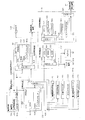
次に、パチンコ機10の電気的構成について説明する。図7は、本パチンコ機10の電気的構成を示すブロック図である。パチンコ機10の主制御装置261(主基板)には、演算装置である1チップマイコンとしてのCPU501が搭載されている。CPU501には、該CPU501により実行される各種の制御プログラムや固定値データを記憶したROM502と、そのROM502内に記憶される制御プログラムの実行に際して各種のデータ等を一時的に記憶するメモリであるRAM503と、割込回路やタイマ回路、データ送受信回路などの各種回路等が内蔵されている。但し、CPU、ROM及びRAMが1チップ化されておらず、それぞれの機能毎にチップ化されている構成であってもよい。
Next, the electrical configuration of the
RAM503は、CPU501の内部レジスタの内容やCPU501により実行される制御プログラムの戻り先番地などが記憶されるスタックエリアと、各種フラグ及びカウンタ、I/O等の値が記憶される作業エリア(作業領域)と、バックアップエリア503aとを備えている。
The
また、RAM503は、パチンコ機10の電源のオフ後においても電源装置313からバックアップ電圧が供給されてデータを保持(バックアップ)できる構成となっており、スタックエリア、作業エリア及びバックアップエリア503aに記憶されるすべてのデータがバックアップされるようになっている。
The
バックアップエリア503aは、停電などの発生により電源が切断された場合において、電源の再入時にパチンコ機10の状態を電源切断前の状態に復帰させるべく、電源切断時(停電発生時を含む。以下同様)のスタックポインタや、各レジスタ、I/O等の値を記憶しておくエリアである。バックアップエリア503aへの書き込みは、通常処理(図11参照)によって電源切断時に実行され、逆にバックアップエリア503aに書き込まれた各値の復帰は、電源入時(停電解消による電源入を含む。以下同様)のメイン処理(図10参照)において実行される。なお、CPU501のNMI端子(ノンマスカブル割込端子)には、停電等の発生による電源断時に、後述する停電監視回路542から出力される停電信号SK1が入力されるように構成されており、停電の発生により、図16の停電処理(NMI割込み処理)が即座に実行される。
In the
なお、少なくともスタックエリアとバックアップエリア503aとに記憶されるデータをバックアップすれば、必ずしもすべてのエリアに記憶されるデータをバックアップする必要はない。例えば、スタックエリアとバックアップエリア503aとに記憶されるデータをバックアップし、作業エリアに記憶されるデータをバックアップしない構成としてもよい。
Note that if data stored in at least the stack area and the
かかるROM502及びRAM503を内蔵したCPU501には、アドレスバス及びデータバス等で構成されるバスライン504を介して入出力ポート505が接続されている。入出力ポート505には、後述するRAM消去スイッチ回路543、払出制御装置311、サブ制御装置262、特別表示装置43、普通図柄表示装置41等が接続されている。この構成により、上述した特別表示装置43および普通図柄表示装置41は、主制御装置261により直接的に制御される。一方、装飾図柄表示装置42は、サブ制御装置262を介して制御される。
An input /
その他、便宜上、各種中継基板等の図示は省略するが、入出力ポート505には、入賞口スイッチ221、カウントスイッチ223、第1契機対応ユニットスイッチ224a,224b、第2契機対応口スイッチ225などの各種検出スイッチや、各種基板などの各種電気部品が接続されている。つまり、主制御装置261には、各種ケーブルコネクタのコネクタを接続するための複数の端子部(基板側コネクタ)が設けられているが、これら端子部等により、入出力ポート505が構成される。
In addition, for convenience, illustration of various relay boards and the like is omitted, but the input /
サブ制御装置262(サブ制御基板)は、演算装置であるCPU551、該CPU551により実行される各種の制御プログラムや固定値データを記憶したROM552、該ROM552内に記憶される制御プログラムの実行に際して各種のデータ等を一時的に記憶するメモリであるRAM553、入出力ポート554、バスライン555を備えるとともに、その他にも図示しない割込回路やタイマ回路、データ送受信回路などの各種回路等を備えている。RAM553は、CPU551による各種プログラムの実行時に使用されるワークデータやフラグを一時的に記憶するメモリである。
The sub-control device 262 (sub-control board) includes a
入出力ポート554には、バスライン555を介してCPU551、ROM552、RAM553が接続されるとともに、表示制御装置45が接続されている。さらに、入出力ポート554には、スピーカSP、各種電飾部及びランプ102〜104が接続されている。
A
サブ制御装置262のCPU551は、例えば主制御装置261から送信される指令信号(例えば変動パターンコマンド)に基づいて表示制御装置45に表示制御を実行させ、装飾図柄表示装置42に表示させる。なお、上記のように、本実施形態では、主制御装置261が制御する特別表示装置43にて大当たりか否かを表示するようになっており、サブ制御装置262が制御する装飾図柄表示装置42では、前記特別表示装置43の表示に合わせた表示が行われる。
The
また、払出制御装置311は、払出装置358により賞球や貸し球の払出制御を行うものである。演算装置であるCPU511は、そのCPU511により実行される制御プログラムや固定値データ等を記憶したROM512と、ワークメモリ等として使用されるRAM513とを備えている。
The
払出制御装置311のRAM513は、主制御装置261のRAM503と同様に、CPU511の内部レジスタの内容やCPU511により実行される制御プログラムの戻り先番地などが記憶されるスタックエリアと、各種フラグ及びカウンタ、I/O等の値が記憶される作業エリア(作業領域)と、バックアップエリア513aとを備えている。
The
RAM513は、パチンコ機10の電源のオフ後においても電源装置313からバックアップ電圧が供給されてデータを保持(バックアップ)できる構成となっており、スタックエリア、作業エリア及びバックアップエリア513aに記憶されるすべてのデータがバックアップされるようになっている。なお、少なくともスタックエリアとバックアップエリア513aとに記憶されるデータをバックアップすれば、必ずしもすべてのエリアに記憶されるデータをバックアップする必要はない。例えば、スタックエリアとバックアップエリア513aとに記憶されるデータをバックアップし、作業エリアに記憶されるデータをバックアップしない構成としてもよい。
The
バックアップエリア513aは、停電などの発生により電源が切断された場合において、電源の再入時にパチンコ機10の状態を電源切断前の状態に復帰させるべく、電源切断時のスタックポインタや、各レジスタ、I/O等の値を記憶しておくエリアである。このバックアップエリア513aへの書き込みは、メイン処理(図25参照)によって電源切断時に実行され、バックアップエリア513aに書き込まれた各値の復帰は電源入時のメイン処理(図25参照)において実行される。なお、主制御装置261のCPU501と同様、CPU511のNMI端子にも、停電等の発生による電源遮断時に停電監視回路542から停電信号SK1が入力されるように構成されており、その停電信号SK1がCPU511へ入力されると、停電時処理としてのNMI割込み処理が即座に実行される。
The backup area 513a has a stack pointer, each register at the time of power off, each register, so that the power of the
作業エリアには、払出制御装置311による賞球の払出許可が設定される払出許可フラグと、主制御装置261から送信されたコマンドを受信した場合に設定されるコマンド受信フラグと、主制御装置261から送信されたコマンドが記憶されるコマンドバッファとが設けられている。
In the work area, a payout permission flag for which the
払出許可フラグは、賞球の払出許可を設定するフラグであり、主制御装置261から賞球の払出を許可する特定のコマンドが送信され、その特定のコマンドを受信した場合にオンされ、初期設定の処理又は電源遮断前へ復帰された場合にオフされる。本実施形態では、特定のコマンドは、払出制御装置311のRAM513の初期処理の指示をする払出初期化コマンドと、賞球の払出を指示する賞球コマンドと、主制御装置261が復電された場合に送信される払出復帰コマンドの3つである。
The payout permission flag is a flag for setting a prize ball payout permission, and is turned on when a specific command for permitting the payout of the prize ball is transmitted from the
コマンド受信フラグは、払出制御装置311がコマンドを受信したか否かを確認するフラグであり、いずれかのコマンドを受信した場合にオンされ、払出許可フラグと同様に、初期設定の処理又は電源遮断前へ復帰された場合にオフされるとともに、後述するコマンド判定処理(図27参照)により受信されたコマンドの判定が行われた場合にオフされる。
The command reception flag is a flag for confirming whether or not the
コマンドバッファは、主制御装置261から送信されるコマンドを一時的に記憶するリングバッファで構成されている。
The command buffer is configured by a ring buffer that temporarily stores commands transmitted from the
かかるROM512及びRAM513を内蔵したCPU511には、アドレスバス及びデータバスで構成されるバスライン514を介して入出力ポート515が接続されている。入出力ポート515には、RAM消去スイッチ回路543、主制御装置261、発射制御装置312、払出装置358等がそれぞれ接続されている。
An input / output port 515 is connected to the
カードユニット接続基板314は、パチンコ機10前面の貸球操作部(球貸しボタン121及び返却ボタン122)と、遊技ホール等にてパチンコ機10の側方に配置されるカードユニット(球貸しユニット)とにそれぞれ電気的に接続され、遊技者による球貸し操作の指令を取り込んでそれをカードユニットに出力するものである。なお、カードユニットを介さずに球貸し装置等から上皿19に遊技球が直接貸し出される現金機では、カードユニット接続基板314を省略することも可能である。
The card
発射制御装置312は、発射装置70による遊技球の発射を許可又は禁止するものであり、発射装置70は、所定条件が整っている場合に駆動が許可される。具体的には、払出制御装置311から発射許可信号が出力されていること、遊技者がハンドル18をタッチしていることをセンサ信号により検出していること、発射を停止させる発射停止スイッチが操作されていないことを条件に、発射装置70が駆動され、ハンドル18の操作量に応じた強度で遊技球が発射される。
The
表示制御装置45は、サブ制御装置262からの指示に従い、装飾図柄表示装置42における装飾図柄の変動表示を実行するものである。この表示制御装置45は、CPU521と、プログラムROM522と、ワークRAM523と、ビデオRAM524と、キャラクタROM525と、ビデオディスプレイプロセッサ(VDP)526と、入力ポート527と、出力ポート529と、バスライン530,531とを備えている。入力ポート527にはサブ制御装置262の入出力ポート554が接続されている。また、入力ポート527には、バスライン530を介して、CPU521、プログラムROM522、ワークRAM523、VDP526が接続されている。また、VDP526にはバスライン531を介して出力ポート529が接続されており、その出力ポート529には液晶表示装置たる装飾図柄表示装置42が接続されている。
The
表示制御装置45のCPU521は、サブ制御装置262から送信される表示コマンドを入力ポート527を介して受信するとともに、受信コマンドを解析し又は受信コマンドに基づき所定の演算処理を行ってVDP526の制御(具体的にはVDP526に対する内部コマンドの生成)を実施する。これにより、装飾図柄表示装置42における表示制御を行う。
The
プログラムROM522は、そのCPU521により実行される各種の制御プログラムや固定値データを記憶するメモリであり、ワークRAM523は、CPU521による各種プログラムの実行時に使用されるワークデータやフラグを一時的に記憶するメモリである。
The
ビデオRAM524は、装飾図柄表示装置42に表示される表示データを記憶するメモリであり、このビデオRAM524の内容を書き替えることにより、装飾図柄表示装置42の表示内容が変更される。キャラクタROM525は、装飾図柄表示装置42に表示される図柄などのキャラクタデータを記憶するメモリである。
The video RAM 524 is a memory for storing display data to be displayed on the decorative
VDP526は、装飾図柄表示装置42に組み込まれたLCDドライバ(液晶駆動回路)を直接操作する一種の描画回路である。VDP526はICチップ化されているため「描画チップ」とも呼ばれ、その実体は、描画処理専用のファームウェアを内蔵したマイコンチップとでも言うべきものである。VDP526は、CPU521、ビデオRAM524等のそれぞれのタイミングを調整してデータの読み書きに介在するとともに、ビデオRAM524に記憶される表示データを所定のタイミングで読み出して装飾図柄表示装置42に表示させる。
The
また、電源装置313は、パチンコ機10の各部に電力を供給する電源部541と、停電等による電源遮断を監視する停電監視回路542と、RAM消去スイッチ323に接続されてなるRAM消去スイッチ回路543とを備えている。
The
電源部541は、図示しない電源経路を通じて、主制御装置261や払出制御装置311等に対して各々に必要な動作電源を供給する。その概要としては、電源部541は、外部より供給される交流24ボルト電源を取り込み、各種スイッチやモータ等を駆動する+12V電源、ロジック用の+5V電源、RAMバックアップ用のバックアップ電源などを生成し、これら+12V電源、+5V電源及びバックアップ電源を主制御装置261や払出制御装置311等に対して供給する。なお、発射制御装置312に対しては払出制御装置311を介して動作電源(+12V電源、+5V電源等)が供給される。同様に、各種スイッチやモータ等には、これらが接続される制御装置を介して動作電源が供給されることとなる。
The
停電監視回路542は、停電等の発生による電源断時に、主制御装置261のCPU501及び払出制御装置311のCPU511の各NMI端子へ停電信号SK1を出力する回路である。停電監視回路542は、電源部541から出力される最大電圧である直流安定24ボルトの電圧を監視し、この電圧が22ボルト未満になった場合に停電(電源断)の発生と判断して、停電信号SK1を主制御装置261及び払出制御装置311へ出力する。この停電信号SK1の出力によって、主制御装置261及び払出制御装置311は、停電の発生を認識し、停電時処理(図16のNMI割込み処理)を実行する。
The power
なお、電源部541は、直流安定24ボルトの電圧が22ボルト未満になった後においても、かかる停電時処理の実行に充分な時間の間、制御系の駆動電圧である5ボルトの出力を正常値に維持するように構成されている。よって、主制御装置261及び払出制御装置311は、停電時処理を正常に実行し完了することができる。
The
RAM消去スイッチ回路543は、RAM消去スイッチ323のスイッチ信号を取り込み、そのスイッチ323の状態に応じて主制御装置261のRAM503及び払出制御装置311のRAM513のバックアップデータをクリアする回路である。RAM消去スイッチ323が押下された際、RAM消去スイッチ回路543は、RAM消去信号SK2を主制御装置261及び払出制御装置311に出力する。RAM消去スイッチ323が押下された状態でパチンコ機10の電源が投入されると(停電解消による電源入を含む)、主制御装置261及び払出制御装置311においてそれぞれのRAM503,513のデータがクリアされる。
The RAM erase
次に、上記の如く構成されたパチンコ機10の動作について説明する。
Next, the operation of the
本実施形態では、主制御装置261内のCPU501は、遊技に際し各種カウンタ情報を用いて抽選(大当たり抽選)を行うこととしている。具体的には、図9に示すように、大当たりの抽選に使用する抽選用乱数カウンタとしての大当たり乱数カウンタC1と、大当たりに際し後述する高確率モード又は低確率モードへの移行決定に使用するモード決定カウンタC2と、特別表示装置43の変動表示時間の決定等に使用する変動選択カウンタC3と、大当たり乱数カウンタC1の初期値設定に使用する初期値乱数カウンタCINIと、特別表示装置43の変動表示時間の決定等に使用する変動種別カウンタCS1,CS2と、普通図柄表示装置41の抽選に使用する普通図柄乱数カウンタC4とを用いることとしている。なお、変動選択カウンタC3は、装飾図柄表示装置42を外れ変動させる際の変動パターンやリーチ種別の抽選にも使用される。また、変動種別カウンタCS1,CS2は、装飾図柄表示装置42の変動パターン選択(演出パターン選択)にも使用される。詳しくは、決定された変動パターンにより、特別表示装置43の変動時間が決定されるとともに、装飾図柄表示装置42における変動態様及び変動時間すなわち演出パターン(演出態様)が決定される。
In the present embodiment, the
カウンタC1,C2,C3,CINI,CS1,CS2,C4は、その更新の都度前回値に1が加算され、上限値に達した後、下限値である0に戻るループカウンタとなっている。各カウンタは定期的に更新され、その更新値がRAM503の所定領域に設定されたカウンタ用バッファに適宜格納される(乱数初期値カウンタCINIを除く)。 Each of the counters C1, C2, C3, CINI, CS1, CS2, and C4 is a loop counter that adds 1 to the previous value every time it is updated and returns to the lower limit value of 0 after reaching the upper limit value. Each counter is periodically updated, and the updated value is appropriately stored in a counter buffer set in a predetermined area of the RAM 503 (except for the random number initial value counter CINI).
RAM503には、1つの実行エリアと4つの保留エリア(保留第1〜保留第4エリア)とからなる記憶エリアとしての第1保留球格納エリア及び第2保留球格納エリアが設けられている。第1保留球格納エリアの各エリアには、第1契機対応ユニット33への遊技球の入賞履歴に合わせて、大当たり乱数カウンタC1、モード決定カウンタC2、及び変動選択カウンタC3の各値が時系列的に格納されるようになっている。また、第2保留球格納エリアの各エリアには、第2契機対応口34への遊技球の通過履歴に合わせて、普通図柄乱数カウンタC4の値が時系列的に格納されるようになっている。
The
各カウンタについて詳しく説明すると、大当たり乱数カウンタC1は、例えば0〜676の範囲内で順に1ずつ加算され、終値としての上限値(つまり676)に達した後、始値としての下限値である0に戻る構成となっている。通常、大当たり乱数カウンタC1が1周した場合、その時点の初期値乱数カウンタCINIの値が当該大当たり乱数カウンタC1の次の初期値として読み込まれる。なお、初期値乱数カウンタCINIは、大当たり乱数カウンタC1と同様のループカウンタであり(値=0〜676)、タイマ割込み毎に1回更新されると共に通常処理の残余時間内で繰り返し更新される。一方、大当たり乱数カウンタC1は定期的に(本実施形態ではタイマ割込み毎に1回)更新され、大当たり乱数カウンタC1の値が大当たり乱数カウンタバッファに格納される。そして、遊技球が第1契機対応ユニット33(上入賞口33a又は下入賞口33b)に入賞したタイミングで大当たり乱数カウンタバッファに格納されている大当たり乱数カウンタC1の値がRAM503の第1保留球格納エリアに格納される。大当たりとなる乱数の値は、低確率状態(通常モードや時間短縮モード等)と高確率状態(高確率モード)とで2種類設定されており、本実施形態では、低確率状態であれば大当たりとなる乱数の値の数は2で、その値は「337,673」であり、高確率状態であれば大当たりとなる乱数の値の数は10で、その値は「67,131,199,269,337,401,463,523,601,661」である。
In detail, each jackpot random number counter C1 is incremented one by one within a range of 0 to 676, for example, and after reaching an upper limit value (ie, 676) as a closing price, 0 is a lower limit value as a starting price. It is the composition which returns to. Normally, when the jackpot random number counter C1 makes one round, the value of the initial value random number counter CINI at that time is read as the next initial value of the jackpot random number counter C1. The initial value random number counter CINI is a loop counter similar to the big hit random number counter C1 (value = 0 to 676), and is updated once for each timer interruption and is repeatedly updated within the remaining time of normal processing. On the other hand, the jackpot random number counter C1 is updated periodically (once every timer interruption in this embodiment), and the value of the jackpot random number counter C1 is stored in the jackpot random number counter buffer. The value of the jackpot random number counter C1 stored in the jackpot random number counter buffer at the timing when the game ball wins the first opportunity corresponding unit 33 (upward winning port 33a or lower winning port 33b) is stored in the first reserved ball of the
ここで、各種遊技モードについて説明する。本実施形態では、遊技モード(遊技状態)が、通常モード(通常状態)及び当該通常モードよりも遊技者に有利な複数の特定モードの間で切換設定される。より詳しくは、特定モードとしては、高確率モード及び時間短縮モードの2つが設定されている。このうち、高確率モードは、次回大当たりまで継続する遊技モードであり、時間短縮モードは、所定期間終了後には次のモードへ移行するモードである。 Here, various game modes will be described. In the present embodiment, the game mode (game state) is switched between a normal mode (normal state) and a plurality of specific modes that are more advantageous to the player than the normal mode. More specifically, as the specific mode, two modes, a high probability mode and a time reduction mode, are set. Among these, the high probability mode is a game mode that continues until the next jackpot, and the time reduction mode is a mode that shifts to the next mode after the predetermined period.
通常モードとは、上記高確率モード等の特定モードでない通常時の状態をいう。従って、通常モード時には、大当たり確率(大当たり状態の当選確率)が通常の低確率となっている。 The normal mode refers to a normal state that is not a specific mode such as the high probability mode. Therefore, in the normal mode, the jackpot probability (winning probability of the jackpot state) is a normal low probability.
また、高確率モードとは、特別表示装置43において「赤」で停止表示されること(装飾図柄表示装置42において予め定められた確変図柄で停止表示されること)によって大当たりになり、その後の大当たり確率が低確率状態時に比べアップした状態をいう。以下の説明では適宜、装飾図柄表示装置42において確変図柄によって大当たりになった場合を「確変大当たり」といい、確変図柄以外の通常図柄によって大当たりになった場合を「通常大当たり」という。
In addition, the high probability mode is a big hit when the
高確率モードにおいては、大当たり確率が高められ、高確率状態となるのであるが、これに加えて、本実施形態では(1)特別表示装置43における変動表示時間を短くした状態(時間短縮状態)、(2)普通図柄表示装置41における変動表示時間を短くした状態、(3)第1契機対応ユニット33(下入賞口33b)の開閉処理に関わる規定時間(開放時間)を通常モードに比べて長くした状態、又は、規定個数(入賞個数)を通常モードに比べて多くした状態、(4)普通図柄表示装置41において「○」図柄が停止表示される旨の当選結果が得られた場合一回につき行う第1契機対応ユニット33の開閉処理の実行回数を通常モードに比べて多くした状態、(5)普通図柄表示装置41において「○」図柄が停止表示される確率(当選確率)を通常モード時の当選確率より高くした状態が付与される。より具体的には、高確率モード時には、第1契機対応ユニット33の開閉部材33cが開状態となり、規定時間(例えば3秒)の経過した場合又は規定個数(例えば3個)の遊技球の入球があった場合に閉状態となる。そして、この開閉処理が2回繰り返し行われる。これによって、第1契機対応ユニット33の下入賞口33bが頻繁に開放されるようになり、大当たり抽選が連続してなされると共に、玉持ちのよい状態となる。これに限らず、高確率モードとしては、大当たり確率(大当たり状態の当選確率)を高めることに加え、上記(1)〜(5)の構成の任意の組合せ(例えば(1)、(2)、(3)、(4)、(5)、(1)と(2)、(1)と(3)、(1)と(4)、(1)と(5)、(2)と(3)、(2)と(4)、(2)と(5)、(3)と(4)、(3)と(5)、(4)と(5)、(1)と(2)と(3)、(1)と(2)と(4)、(1)と(2)と(5)、(1)と(3)と(4)、(1)と(3)と(5)、(1)と(4)と(5)、(2)と(3)と(4)、(2)と(3)と(5)、(2)と(4)と(5)、(3)と(4)と(5)、(1)と(2)と(3)と(4)、(1)と(2)と(3)と(5)、(1)と(2)と(4)と(5)、(1)と(3)と(4)と(5)、(2)と(3)と(4)と(5))を採用できる。なお、上記(2)〜(5)の状態により、第1契機対応ユニット33の下入賞口33bにおける単位時間あたりの閉状態に対する開状態の割合が通常モード時の割合より高い状態となる。つまり、このような状態が本実施形態における高入球状態に相当する。従って、上記高確率モードは、高確率・時間短縮・高入球モードと言い換えることができる。これに対し、通常モード時のように、上記(2)〜(5)の状態ではない状態は低入球状態に相当する。
In the high probability mode, the jackpot probability is increased and a high probability state is obtained. In addition, in this embodiment, (1) a state in which the variable display time in the
また、時間短縮モードとは、特別表示装置43において「緑」で停止表示されること(装飾図柄表示装置42において予め定められた確変図柄以外の通常図柄で停止表示されること)によって大当たりになり、その後特別表示装置43の変動表示が100回行われる間設定される遊技モードであり、通常モードよりも遊技者に有利な状態をいう。時間短縮モードは、大当たり確率が通常モード時と同じ低確率であり、かつ、第1契機対応ユニット33の下入賞口33bにおける単位時間あたりの閉状態に対する開状態の割合が通常モード時の割合より高い遊技モードである。本実施形態では、高確率モード時に付与される上記(1)〜(5)の状態が同様に付与される。つまり、大当たり確率(大当たり状態の当選確率)の違いを除いて同様の状態(時間短縮状態及び高入球状態)となる。もちろん、高確率モード時と同様に、上記(1)〜(5)の構成の任意の組合せを採用できる。従って、上記時間短縮モードは、低確率・時間短縮・高入球モードと言い換えることができる。
In addition, the time reduction mode is a big hit when the
モード決定カウンタC2は、例えば0〜9の範囲内で順に1ずつ加算され、上限値(つまり9)に達した後、下限値である0に戻る構成となっている。本実施形態では、モード決定カウンタC2によって、大当たり後、高確率モードへ移行させるか否かが決定されるようになっている。具体的には、カウンタの値が「1,3,5,7,9」という奇数であれば高確率モードへの移行が決定され、「0,2,4,6,8」という偶数であれば時間短縮モードへの移行が決定される。なお、ここでは移行という文言を用いたが、もともと高確率モードにある場合にカウンタ値が奇数であれば高確率モードが継続されることになり、もともと時間短縮モードにある場合にカウンタ値が偶数であれば時間短縮モードが継続されることになる。モード決定カウンタC2は定期的に(本実施形態ではタイマ割込み毎に1回)更新され、モード決定カウンタC2の値がモード決定カウンタバッファに格納される。そして、遊技球が第1契機対応ユニット33(上入賞口33a又は下入賞口33b)に入賞したタイミングで、モード決定カウンタバッファに格納されているモード決定カウンタC2の値がRAM503の第1保留球格納エリアに格納される。
For example, the mode determination counter C2 is incremented one by one within a range of 0 to 9, for example, and after reaching the upper limit value (that is, 9), the mode determination counter C2 returns to the lower limit value of 0. In the present embodiment, the mode determination counter C2 determines whether or not to shift to the high probability mode after the big hit. Specifically, if the counter value is an odd number such as “1, 3, 5, 7, 9”, the transition to the high probability mode is determined, and if the counter value is an even number such as “0, 2, 4, 6, 8”. In this case, the transition to the time reduction mode is determined. Although the term “transition” is used here, the high probability mode is continued if the counter value is odd when originally in the high probability mode, and the counter value is even when originally in the time reduction mode. If so, the time shortening mode is continued. The mode determination counter C2 is updated periodically (once every timer interruption in this embodiment), and the value of the mode determination counter C2 is stored in the mode determination counter buffer. The value of the mode determination counter C2 stored in the mode determination counter buffer is the first reserved ball in the
また、変動選択カウンタC3は、例えば0〜238の範囲内で順に1ずつ加算され、上限値(つまり238)に達した後、下限値である0に戻る構成となっている。本実施形態では、変動選択カウンタC3によって、装飾図柄に関してリーチが発生した後、最終停止図柄がリーチ図柄の前後に1つだけずれて停止する「前後外れリーチ」と、同じくリーチ発生した後最終停止図柄がリーチ図柄の前後以外で停止する「前後外れ以外リーチ」と、リーチ発生しない「完全外れ」とを抽選することとしており、例えば、C3=0,1が前後外れリーチに該当し、C3=2〜21が前後外れ以外リーチに該当し、C3=22〜238が完全外れに該当する。なお、リーチの抽選は、抽選確率の状態や変動開始時の始動保留球数等に応じて各々個別に設定されるものであってもよい。変動選択カウンタC3は定期的に(本実施形態ではタイマ割込み毎に1回)更新され、変動選択カウンタバッファに変動選択カウンタC3の値が格納される。そして、遊技球が第1契機対応ユニット33(上入賞口33a又は下入賞口33b)に入賞したタイミングで、変動選択カウンタバッファに格納されている変動選択カウンタC3の値がRAM503の第1保留球格納エリアに格納される。
Further, the variation selection counter C3 is configured so that, for example, one by one is added in order within a range of 0 to 238, for example, and after reaching the upper limit value (that is, 238), it returns to 0 that is the lower limit value. In this embodiment, after the reach is generated with respect to the decorative symbol by the variation selection counter C3, the final stop symbol is shifted by one by one before and after the reach symbol and stopped, and the last stop after the occurrence of reach is also performed. “Reach other than front / rear detachment” where the symbol stops other than before and after the reach symbol and “completely disengagement” where reach does not occur are selected by lottery. For example, C3 = 0, 1 corresponds to front / rear outreach and C3 = 2 to 21 correspond to reach other than front / rear disengagement, and C3 = 22 to 238 corresponds to complete disengagement. The reach lottery may be individually set according to the state of the lottery probability, the number of starting reserved balls at the start of change, and the like. The fluctuation selection counter C3 is updated periodically (once every timer interruption in this embodiment), and the value of the fluctuation selection counter C3 is stored in the fluctuation selection counter buffer. The value of the variation selection counter C3 stored in the variation selection counter buffer is the first reserved ball in the
また、2つの変動種別カウンタCS1,CS2のうち、一方の変動種別カウンタCS1は、例えば0〜198の範囲内で順に1ずつ加算され、上限値(つまり198)に達した後、下限値である0に戻る構成となっており、他方の変動種別カウンタCS2は、例えば0〜240の範囲内で順に1ずつ加算され、上限値(つまり240)に達した後、下限値である0に戻る構成となっている。以下の説明では、CS1を「第1変動種別カウンタ」、CS2を「第2変動種別カウンタ」ともいう。図9中でもこのように表記した。第1変動種別カウンタCS1によって、いわゆるノーマルリーチ、スーパーリーチ、プレミアムリーチ等、装飾図柄のリーチ種別(リーチパターン)やその他大まかな図柄変動態様が決定され、第2変動種別カウンタCS2によって、リーチ発生後に最終停止図柄(本実施形態では中図柄)が停止するまでの経過時間(言い換えれば、変動図柄数)などより細かな図柄変動態様が決定される。従って、これらの変動種別カウンタCS1,CS2を組合わせることで、変動パターンの多種多様化を容易に実現できる。また、第1変動種別カウンタCS1だけで図柄変動態様を決定したり、第1変動種別カウンタCS1と停止図柄とを組合わせて同じく図柄変動態様を決定したりすることも可能である。 In addition, one of the two variation type counters CS1 and CS2 is incremented one by one within a range of 0 to 198, for example, and reaches the upper limit value (that is, 198), and then reaches the lower limit value. The other variation type counter CS2 is incremented one by one within a range of 0 to 240, for example, and reaches the upper limit value (that is, 240) and then returns to the lower limit value of 0. It has become. In the following description, CS1 is also referred to as “first variation type counter”, and CS2 is also referred to as “second variation type counter”. This is also shown in FIG. The first variation type counter CS1 determines the reach type (reach pattern) of the decorative symbol such as so-called normal reach, super reach, premium reach, and other rough symbol variation modes, and the second variation type counter CS2 determines the final after the reach occurrence. A more detailed symbol variation mode such as an elapsed time (in other words, the number of variation symbols) until the stop symbol (in this embodiment, the middle symbol) stops is determined. Accordingly, a variety of variation patterns can be easily realized by combining these variation type counters CS1 and CS2. It is also possible to determine the symbol variation mode only by the first variation type counter CS1, or to determine the symbol variation mode in combination by combining the first variation type counter CS1 and the stop symbol.
なお、本実施形態では、「大当たり」が発生する場合には、ノーマルリーチ、スーパーリーチ、プレミアムリーチのうちいずれかが選択され、「前後外れリーチ」が発生する場合には、ノーマルリーチ、スーパーリーチのうちどちらかが選択され、「前後外れ以外リーチ」が発生する場合にはノーマルリーチが選択される。また、「完全外れ」となる場合には、ノーマルリーチ、スーパーリーチ、プレミアムリーチのいずれも選択されない。 In the present embodiment, when a “big hit” occurs, one of normal reach, super reach, and premium reach is selected. When either one is selected and “reach other than front / rear out” occurs, normal reach is selected. In addition, in the case of “completely off”, none of normal reach, super reach, and premium reach is selected.
また、変動種別カウンタCS1,CS2は、後述する通常処理が1回実行される毎に1回更新され、当該通常処理の残余時間内でも繰り返し更新される。そして、装飾図柄表示装置42による装飾図柄の変動開始時における変動パターン決定に際してCS1,CS2のバッファ値が取得される。
Further, the variation type counters CS1 and CS2 are updated once every time a normal process described later is executed once, and are repeatedly updated even within the remaining time of the normal process. Then, the buffer values of CS1 and CS2 are acquired when determining the variation pattern at the start of variation of the decorative symbol by the decorative
なお、各カウンタの大きさや範囲は一例にすぎず任意に変更できる。但し、大当たり乱数カウンタC1、変動選択カウンタC3、変動種別カウンタCS1,CS2の大きさは何れも異なる素数とし、いかなる場合にも同期しない数値としておくのが望ましい。 In addition, the magnitude | size and range of each counter are only examples, and can be changed arbitrarily. However, it is desirable that the big hit random number counter C1, the variation selection counter C3, and the variation type counters CS1 and CS2 are different prime numbers and are not synchronized in any case.
また、普通図柄乱数カウンタC4は、例えば0〜250の範囲内で順に1ずつ加算され、上限値(つまり250)に達した後、下限値である0に戻るループカウンタとして構成されている。普通図柄乱数カウンタC4は定期的に(本実施形態ではタイマ割込み毎に1回)更新され、遊技球が左右何れかの第2契機対応口34を通過した時に普通図柄乱数カウンタC4の値が取得される。通常、当選となる乱数の値の数は149あり、その範囲は「5〜153」である。一方、高確率モード時及び時間短縮モード時、つまり第1契機対応ユニット33が高入球状態にある場合においては224あり、その範囲は「5〜228」である。つまり、普通図柄表示装置41における「○」図柄の停止確率が通常モードに比べ高くなる。そして、当選となる普通図柄乱数カウンタC4の値が取得された場合、普通図柄表示装置41において変動表示が所定時間行われた後、当選に対応する図柄(本例では「○」)が停止表示され、第1契機対応ユニット33が所定時間の間、作動状態となる。また、高確率モード時及び時間短縮モード時においては、普通図柄表示装置41において抽選の結果が表示されるまでの時間(普通図柄の変動表示時間)が短縮される等して、第1契機対応ユニット33が高入球状態となる割合が多くなる。これによって、第1契機対応ユニット33の下入賞口33bが頻繁に開放されるようになり、大当たり抽選が連続してなされる。
Further, the normal symbol random number counter C4 is configured as a loop counter that is incremented one by one within a range of 0 to 250, for example, and reaches the upper limit value (that is, 250) and then returns to the lower limit value of 0. The normal symbol random number counter C4 is updated periodically (once every timer interruption in the present embodiment), and the value of the normal symbol random number counter C4 is acquired when the game ball passes through the left or right second opportunity corresponding port 34. Is done. Normally, there are 149 random numbers to be won, and the range is “5 to 153”. On the other hand, in the high probability mode and the time reduction mode, that is, in the case where the first
次いで、主制御装置261内のCPU501により実行される各制御処理をフローチャートを参照しながら説明する。かかるCPU501の処理としては大別して、電源投入に伴い起動されるメイン処理と、定期的に(本実施形態では2msec周期で)起動されるタイマ割込み処理と、NMI端子(ノンマスカブル端子)への停止信号の入力により起動されるNMI割込み処理とがあり、説明の便宜上ここでは、先ずタイマ割込み処理とNMI割込み処理とを説明し、その後でメイン処理を説明する。
Next, each control process executed by the
図12は、タイマ割込み処理を示すフローチャートであり、本処理は主制御装置261のCPU501により例えば2msec毎に実行される。
FIG. 12 is a flowchart showing the timer interrupt process. This process is executed by the
図12において、先ずステップS301では、各種入球検出スイッチの読み込み処理を実行する。詳しくは後述するが、ここでは主制御装置261に接続されている各種入球検出スイッチの状態を読み込むと共に、当該スイッチの状態を判定して検出情報を保存する。
In FIG. 12, first, in step S301, various incoming ball detection switch reading processes are executed. As will be described in detail later, here, the state of various ball detection switches connected to the
ステップS302では、乱数初期値更新処理を実行する。具体的には、乱数初期値カウンタCINIを1インクリメントすると共に、そのカウンタ値が最大値(本実施の形態では676)に達した際0にクリアする。 In step S302, random number initial value update processing is executed. Specifically, the random number initial value counter CINI is incremented by 1 and cleared to 0 when the counter value reaches the maximum value (676 in this embodiment).
また、ステップS303では乱数更新処理を実行する。具体的には、大当たり乱数カウンタC1、モード決定カウンタC2、変動選択カウンタC3及び普通図柄乱数カウンタC4をそれぞれ1インクリメントすると共に、それらのカウンタ値が最大値(本実施の形態ではそれぞれ、676,9,238,250)に達した際それぞれ0にクリアする。そして、各カウンタC1,C2,C3,C4の更新値を、RAM503の該当するバッファ領域に格納する。
In step S303, random number update processing is executed. Specifically, the jackpot random number counter C1, the mode determination counter C2, the variation selection counter C3, and the normal symbol random number counter C4 are each incremented by 1 and their counter values are the maximum values (in this embodiment, 676, 9 respectively. , 238, 250) is cleared to 0 respectively. Then, the updated values of the counters C1, C2, C3, and C4 are stored in the corresponding buffer area of the
その後、ステップS304では、第1契機対応ユニット33への入賞に伴う始動入賞処理を実行し、ステップS305では、第2契機対応口34への遊技球の通過に伴う第2契機対応口通過処理を実行する。その後、タイマ割込み処理を一旦終了する。
Thereafter, in step S304, a start winning process associated with winning the first
ここで、ステップS301のスイッチ読み込み処理について詳しく説明する。なお、このスイッチ読み込み処理では、各入球検出スイッチ(入賞口スイッチ221、カウントスイッチ223、第1契機対応ユニットスイッチ224a,224b、第2契機対応口スイッチ225)を個々に監視して、個別に同様の処理が行われる。従って、ここでは入賞口スイッチ221に係るスイッチ読み込み処理を一例に図13を参照して詳しく説明するが、他の入球検出スイッチに関しても図13に示す処理と同様の処理が行われる。
Here, the switch reading process in step S301 will be described in detail. In this switch reading process, each ball detection switch (winning
先ずステップS401では、入賞口スイッチ221からの入力信号の信号レベルをチェックする。この処理の機能が本実施形態における信号監視手段を構成する。
First, in step S401, the signal level of the input signal from the winning
例えば遊技球が入賞口スイッチ221の通過孔を通過してない通常時には、入賞口スイッチ221からは+12Vのハイレベル信号(H)が出力され〔図32(a)のタイミングt1参照〕、主制御装置261側では反転回路229を経てCPU501に基準電位0Vのローレベル信号(L)が入力される〔図32(b)のタイミングt1参照〕。図32(a)は、入賞口スイッチ221からの出力信号を説明するためのタイミングチャートであり、図32(b)は、CPU501への入力信号を説明するためのタイミングチャートである。
For example, when the game ball is not passing through the passage hole of the winning
一方、一般入賞口31へ遊技球が入球して、遊技球が入賞口スイッチ221の通過孔を通過している最中には、入賞口スイッチ221からローレベル信号(L)が出力され〔図32(a)のタイミングt2,t3参照〕、主制御装置261側では反転回路229を経てCPU501にハイレベル信号(H)が入力される〔図32(b)のタイミングt2,t3参照〕。
On the other hand, while a game ball enters the general winning
続くステップS402では、ステップS401にてチェックした信号レベルを、RAM503の作業エリアに設けられた入賞口スイッチ221用の信号レベルバッファに記憶する。
In the subsequent step S402, the signal level checked in step S401 is stored in the signal level buffer for the winning
なお、信号レベルバッファは、各入球検出スイッチ(入賞口スイッチ221、カウントスイッチ223、第1契機対応ユニットスイッチ224a,224b、第2契機対応口スイッチ225)に対応して設けられており、各入球検出スイッチ毎の信号レベルがそれぞれ記憶される。信号レベルバッファが本実施形態におけるレベル記憶手段に相当する。
In addition, the signal level buffer is provided corresponding to each ball detection switch (
信号レベルバッファは、リングバッファにより構成されている。リングバッファとは、概念上、バッファ領域内の先頭アドレスと最終アドレスとがリング状に?がり、ライトポインタとリードポインタの2つのアドレスポインタを用いて先頭アドレスから順に書き込んで行き、最終アドレスまで到達すると再び先頭アドレスに戻って書き込めるように制御されるバッファである。そして、ライトポインタの示す所定アドレス位置にデータの書込みが行われた後、当該ライトポインタの値が次のアドレスを示す値に更新される。同様に、リードポインタの示す所定アドレス位置からデータの読出しが行われた後、当該リードポインタの値が次のアドレスを示す値に更新される。 The signal level buffer is configured by a ring buffer. What is a ring buffer conceptually? Is the start address and end address in the buffer area ring-shaped? Thus, the buffer is controlled so that writing is performed in order from the top address using the two address pointers of the write pointer and the read pointer, and when the final address is reached, the write back to the top address can be performed again. After data is written at a predetermined address position indicated by the write pointer, the value of the write pointer is updated to a value indicating the next address. Similarly, after data is read from a predetermined address position indicated by the read pointer, the value of the read pointer is updated to a value indicating the next address.
また、本実施形態の各信号レベルバッファを構成するリングバッファには、最も新しい過去200msec分すなわち100周期分のデータが記憶されるとともに、これを越えた古いデータから順に消去される構成となっている。また、リードポインタの位置は最新のデータの記憶された所定アドレス位置を示すようになっており、後述するように当該リードポインタの位置を基準に過去複数回分のデータが読み出される構成となっている。 In addition, the latest 200 msec data, that is, 100 cycles of data is stored in the ring buffer that constitutes each signal level buffer of this embodiment, and the oldest data beyond this is erased in order. Yes. Further, the position of the read pointer indicates a predetermined address position where the latest data is stored. As described later, the data for the past plural times is read based on the position of the read pointer. .
ステップS402の説明に戻り、入賞口スイッチ221用の信号レベルバッファには、2msec周期で信号レベルをチェックする毎に、当該信号レベルに対応した論理値が順にライトポインタの示す所定アドレス位置に書き込まれていく。ここで、CPU501への入力信号の信号レベルが「H(ハイ)」の場合には、これを示すレベル情報としての論理値「1」が記憶され、信号レベルが「L(ロー)」の場合には、これを示すレベル情報としての論理値「0」が記憶される。
Returning to the description of step S402, each time the signal level is checked at a cycle of 2 msec, the logical value corresponding to the signal level is sequentially written in the predetermined address position indicated by the write pointer in the signal level buffer for the winning
その後、ステップS403において、一般入賞口31へ遊技球の入球の有無を判定するための前処理である演算処理を行う。
Thereafter, in step S403, a calculation process which is a pre-process for determining whether or not a game ball has entered the general winning
より詳しくは、信号レベルバッファに記憶された最近の過去3回分のデータのうちの最先のデータ(最も古いデータ)の論理反転処理を行うとともに、当該論理反転された最先のデータ及び残り2回分のデータすべての論理積を算出する。そして、この値を、RAM503の作業エリアにて一旦記憶する。この処理の機能が本実施形態における論理反転手段や論理積算出手段を構成する。
More specifically, logical inversion processing is performed on the earliest data (oldest data) of the latest three data stored in the signal level buffer, and the earliest data that has been logically inverted and the remaining 2 data. Calculate the logical product of all the batch data. Then, this value is temporarily stored in the work area of the
例えば、図32(b)に示すように、タイミングt1,t2,t3において記憶された信号レベルの論理値が「0」,「1」,「1」である場合、最先のデータの論理反転処理を行うと、最先のデータは「1」となる。従って、このデータと他の2回分のデータの論理積は「1」となる。 For example, as shown in FIG. 32B, when the logical values of the signal levels stored at timings t1, t2, and t3 are “0”, “1”, and “1”, the logical inversion of the earliest data When processing is performed, the earliest data is “1”. Therefore, the logical product of this data and the other two data is “1”.
続くステップS404では、ステップS403にて算出された論理積の値が「1」であるか否かを判別する。ここで論理積の値が「1」となった場合には、信号レベルが「L」から「H」に切り替わったことを意味するため、これをもって一般入賞口31への入球有りと判断し、ステップS405において入賞口スイッチ221(一般入賞口31)用の入球判別フラグの値に「1」を設定する。なお、入球判別フラグは、入球の有無を判別するための判別子であり、各入球検出スイッチに対応してそれぞれ設けられている。そして、ステップS304の始動入賞処理や、ステップS305の第2契機対応口通過処理では、これを基に入球の有無を判断している。 In a succeeding step S404, it is determined whether or not the logical product value calculated in the step S403 is “1”. Here, when the logical product value is “1”, it means that the signal level has been switched from “L” to “H”. In step S405, “1” is set to the value of the ball entry discrimination flag for the prize opening switch 221 (general winning opening 31). In addition, the entrance discrimination flag is a discriminator for discriminating whether or not there is an entrance and is provided corresponding to each entrance detection switch. In the start winning process in step S304 and the second opportunity corresponding port passing process in step S305, the presence / absence of a ball is determined based on this.
一方、論理積の値が「0」の場合には、過去4msecの間、信号レベルが「L」のままか若しくは「H」のまま切り替わらなかった、又は信号レベルが「H」から「L」に切り替わったこと等を意味するため、これをもって一般入賞口31への入球無しと判断し、ステップS406において入賞口スイッチ221用の入球判別フラグの値に「0」を設定する。上述したステップS403〜S406の一連の処理(入球判定処理)の機能が本実施形態における入球判定手段を構成する。
On the other hand, when the logical product value is “0”, the signal level remains “L” or “H” for the past 4 msec, or the signal level does not switch from “H” to “L”. Therefore, it is determined that there is no entry to the general winning
ステップS405,S406に続くステップS407では、入賞口スイッチ221からの入力信号の有効性を判定するための前処理である演算処理を行う。
In step S407 following steps S405 and S406, a calculation process, which is a pre-process for determining the validity of the input signal from the winning
より詳しくは、信号レベルバッファに記憶された最近の過去11回分のデータのうちの最先のデータ(最も古いデータ)の論理反転処理を行うとともに、当該論理反転されたデータ及び残り10回分のデータすべての論理積を算出する。そして、この値を、RAM503の作業エリアにて一旦記憶する。この処理の機能が本実施形態における論理反転手段や論理積算出手段を構成する。
More specifically, the logic inversion processing of the earliest data (oldest data) of the latest 11 data stored in the signal level buffer is performed, and the logic inverted data and the remaining 10 data are processed. Calculate all logical products. Then, this value is temporarily stored in the work area of the
例えば、図33に示すように、タイミングt1〜t11において記憶された信号レベルの論理値がt1=「0」,t2=「1」,t3=「1」,t4=「1」,t5=「1」,t6=「1」,t7=「1」,t8=「1」,t9=「1」,t10=「1」,t11=「1」である場合、最先のデータの論理反転処理を行うと、最先のデータは「1」となる。従って、このデータと他の10回分のデータの論理積は「1」となる。 For example, as shown in FIG. 33, the logical values of the signal levels stored at the timings t1 to t11 are t1 = “0”, t2 = “1”, t3 = “1”, t4 = “1”, t5 = “ 1 ”, t6 =“ 1 ”, t7 =“ 1 ”, t8 =“ 1 ”, t9 =“ 1 ”, t10 =“ 1 ”, t11 =“ 1 ”, logical inversion processing of the earliest data As a result, the earliest data is “1”. Therefore, the logical product of this data and the other 10 data is “1”.
続くステップS408では、ステップS407にて算出された論理積の値が「1」であるか否かを判別する。ここで論理積の値が「1」となった場合には、信号レベルが「L」から「H」に切り替わった後、少なくとも18msecの間、ハイレベル信号が継続して入力されていることを意味するため、これをもって入力信号が遊技球の入球に基づくものではなく何らかの異常有りと判断し、ステップS409において入賞口スイッチ221用の入球異常判定フラグの値に「1」を設定する。なお、入球異常判定フラグは、入球検出スイッチに関わる異常を判別するための判別子であり、各入球検出スイッチに対応してそれぞれ設けられている。つまり、継続して規定期間18msecを越えるハイレベル信号は、何らかの故障や、不正行為による人為的な動作などに基く異常な入力信号であると判断される。また、本実施形態では、上記入球異常判定フラグの値に基づき、後述する通常処理の外部出力処理において、遊技ホールのホールコンピュータへ入球エラー信号が出力される。
In the subsequent step S408, it is determined whether or not the logical product value calculated in step S407 is “1”. When the logical product value is “1”, it is confirmed that the high level signal is continuously input for at least 18 msec after the signal level is switched from “L” to “H”. For this reason, it is determined that the input signal is not based on the entry of the game ball and that there is some abnormality, and in step S409, the value of the ball entry abnormality determination flag for the
そして、ステップS409に続くステップS410にて、RAM503の作業エリアに設けられた異常計数カウンタの値に1を加算する。異常計数カウンタは、異常有りと判定された回数を加算して記憶していく異常回数記憶手段である。異常計数カウンタの値は、RAM消去スイッチ323の操作によりクリアできる。
Then, in step S410 following step S409, 1 is added to the value of the abnormality count counter provided in the work area of the
一方、ステップS408にて、論理積の値が「0」と判定された場合には、少なくとも過去20msecの間、信号レベルが「L」のままか、又は信号レベルが「L」から「H」に切り替わった後、18msecの間に再度「L」に切り替わっていること等を意味するため、これをもって異常無しと判断し、ステップS411において入賞口スイッチ221用の入球異常判定フラグの値に「0」を設定する。なお、過去20msecの間、信号レベルが「H」のまま切り替わらなかった場合も、論理積の値が「0」となり、異常無しと判定されてしまうが、この場合、その前段階、すなわち信号レベルが過去18msecの間、「H」のまま切り替わらなかった時点で、一旦異常有りと判定されるため何ら問題ない。上述したステップS407〜S409,ステップS411の一連の処理(異常判定処理)の機能が本実施形態における異常判定手段を構成する。
On the other hand, if it is determined in step S408 that the logical product value is “0”, the signal level remains “L” for at least the past 20 msec, or the signal level changes from “L” to “H”. This means that it has been switched to “L” again within 18 msec after switching to, so that it is determined that there is no abnormality, and in step S411, the value of the entrance abnormality determination flag for the winning
ステップS410,S411に続くステップS412では、異常計数カウンタの値が5以上か否かを判定する。 In step S412, following steps S410 and S411, it is determined whether or not the value of the abnormality count counter is 5 or more.
ここで、異常計数カウンタの値が5以上と判定された場合には、ステップS413において、報知設定処理を行った後、本処理を終了する。一方、異常計数カウンタの値が5以上でないと判定された場合には、そのまま本処理を終了する。 Here, when it is determined that the value of the abnormality count counter is 5 or more, the notification setting process is performed in step S413, and then this process is terminated. On the other hand, when it is determined that the value of the abnormality count counter is not 5 or more, the present process is terminated as it is.
ステップS413の報知設定処理では、異常有りを報知するための設定処理が行われる。例えば、本実施形態では、この報知設定処理の設定内容に基づき、エラー表示ランプ104の点滅制御が行われる。
In the notification setting process in step S413, a setting process for notifying that there is an abnormality is performed. For example, in this embodiment, the blinking control of the
より具体的には、異常計数カウンタの値が5以上と判定された場合には、エラー表示ランプ104を点滅させるためのコマンドをサブ制御装置262へ出力するための設定を行う。これに基づき、後述する通常処理の外部出力処理において、サブ制御装置262に対し当該コマンドが出力され、サブ制御装置262によってエラー表示ランプ104の点滅制御が行われる。このエラー表示ランプ104や、入球エラー信号を出力する外部中継端子板240などが本実施形態における報知手段を構成する。
More specifically, when it is determined that the value of the abnormality count counter is 5 or more, a setting for outputting a command for blinking the
ここで、ステップS304の始動入賞処理について図14のフローチャートを参照して説明する。ステップS501では、遊技球が第1契機対応ユニット33(上入賞口33a又は下入賞口33b)に入賞したか否かを第1契機対応ユニットスイッチ224a,224bに対応する上記入球判別フラグの値に基づき判別する。遊技球が第1契機対応ユニット33に入賞したと判別されると、続くステップS502では、始動保留球数Nが上限値(本実施形態では4)未満であるか否かを判別する。第1契機対応ユニット33への入賞があり、且つ始動保留球数N<4であることを条件にステップS503に進み、始動保留球数Nをインクリメントする。
Here, the start winning process in step S304 will be described with reference to the flowchart of FIG. In step S501, whether or not the game ball has won the first opportunity corresponding unit 33 (upper winning opening 33a or lower winning opening 33b) is determined by the value of the above described ball determination flag corresponding to the first opportunity corresponding unit switches 224a and 224b. Determine based on. If it is determined that the game ball has won the first
また、続くステップS504では、当否に関わる乱数を取得する。具体的には、上記ステップS303の乱数更新処理で更新した大当たり乱数カウンタC1、モード決定カウンタC2及び変動選択カウンタC3の各値を、RAM503の第1保留球格納エリアの空き記憶エリアのうち最初のエリアに格納する。その後、始動入賞処理を一旦終了する。
In subsequent step S504, a random number related to the success or failure is acquired. Specifically, the values of the jackpot random number counter C1, the mode determination counter C2, and the variation selection counter C3 updated by the random number update process in step S303 are used as the first free storage area in the first reserved ball storage area of the
次に、ステップS305の第2契機対応口通過処理について図15のフローチャートを参照して説明する。ステップS601では、遊技球が第2契機対応口34を通過したか否かを第2契機対応口スイッチ225に対応する上記入球判別フラグの値に基づき判別する。遊技球が第2契機対応口34を通過したと判別されると、続くステップS602では、普通図柄表示装置41の保留球数Nが上限値(本実施形態では4)未満であるか否かを判別する。第2契機対応口34への通過があり、且つ保留球数N<4であることを条件にステップS603に進み、保留球数Nを1インクリメントする。また、続くステップS604では、当否に関わる乱数を取得する。具体的には、上記ステップS303の乱数更新処理で更新した普通図柄乱数カウンタC4の値を、RAM503の第2保留球格納エリアの空き記憶エリアのうち最初のエリアに格納する。その後、第2契機対応口通過処理を一旦終了する。
Next, the second opportunity corresponding port passing process of step S305 will be described with reference to the flowchart of FIG. In step S601, it is determined whether or not the game ball has passed through the second opportunity corresponding port 34 based on the value of the above-mentioned entrance determination flag corresponding to the second opportunity corresponding
図16は、NMI割込み処理を示すフローチャートであり、本処理は、主制御装置261のCPU501により停電の発生等によるパチンコ機10の電源断時に実行される。このNMI割込みにより、電源断時の主制御装置261の状態がRAM503のバックアップエリア503aに記憶される。
FIG. 16 is a flowchart showing the NMI interrupt processing. This processing is executed by the
すなわち、停電の発生等によりパチンコ機10の電源が遮断されると、停電信号SK1が停電監視回路542から主制御装置261内のCPU501のNMI端子に出力される。すると、CPU501は実行中の制御を中断してNMI割込み処理を開始し、ステップS701において、電源断の発生情報の設定として電源断の発生情報をRAM503のバックアップエリア503aに記憶してNMI割込み処理を終了する。
That is, when the power of the
なお、上記のNMI割込み処理は払出制御装置311でも同様に実行され、かかるNMI割込みにより、電源断の発生情報がRAM513のバックアップエリア513aに記憶される。すなわち、停電の発生等によりパチンコ機10の電源が遮断されると、停電信号SK1が停電監視回路542から払出制御装置311内のCPU511のNMI端子に出力され、CPU511は実行中の制御を中断して図16のNMI割込み処理を開始する。その内容は上記説明の通りである。
The above NMI interrupt processing is executed in the same manner in the
次に、主制御装置261内のCPU501により実行されるメイン処理の流れを図10のフローチャートを参照しながら説明する。このメイン処理は電源投入時のリセットに伴い起動される。
Next, the flow of main processing executed by the
先ずはじめに、ステップS101では、電源投入に伴う初期設定処理を実行する。具体的には、スタックポインタに予め決められた所定値を設定すると共に、サブ側の制御装置(サブ制御装置262,払出制御装置311等)が動作可能な状態になるのを待つために例えば1秒程度、ウェイト処理を実行する。続くステップS103では、RAMアクセスを許可する。
First, in step S101, an initial setting process associated with power-on is executed. Specifically, for example, 1 is set in order to set a predetermined value in the stack pointer and wait for the sub-side control device (
その後、CPU501内のRAM503に関してデータバックアップの処理を実行する。つまり、ステップS104では、電源装置313に設けたRAM消去スイッチ323が押下(ON)されているか否かを判別し、押下されていれば、バックアップデータをクリア(消去)するべく、ステップS113へ移行する。一方、RAM消去スイッチ323が押下されていなければ、続くステップS105で、RAM503のバックアップエリア503aに電源断の発生情報が設定されているか否かを判別する。ここで、設定されていなければ、バックアップデータは記憶されていないので、この場合もステップS113へ移行する。バックアップエリア503aに電源断の発生情報が設定されていれば、ステップS106でRAM判定値を算出し、続くステップS107では、そのRAM判定値が電源断時に保存したRAM判定値と一致するか否か、すなわちバックアップの有効性を判別する。ここで算出したRAM判定値が電源断時に保存したRAM判定値と一致しなければ、バックアップされたデータは破壊されているので、この場合もステップS113へ移行する。
Thereafter, data backup processing is executed for the
ステップS113の処理では、サブ側の制御装置となるサブ制御装置262及び払出制御装置311等を初期化するために、初期化コマンドを送信する。その後、RAMの初期化処理(ステップS114等)に移行する。なお、RAM判定値は、例えばRAM503の作業領域アドレスにおけるチェックサム値である。このRAM判定値に代えて、RAM503の所定のエリアに書き込まれたキーワードが正しく保存されているか否かによりバックアップの有効性を判断することも可能である。
In the process of step S113, an initialization command is transmitted in order to initialize the
上述したように、本パチンコ機10では、例えばホールの営業開始時など、電源投入時に初期状態に戻したい場合にはRAM消去スイッチ323を押しながら電源が投入される。従って、RAM消去スイッチ323がONされていれば、RAMの初期化処理(ステップS114等)に移行する。また、電源断の発生情報が設定されていない場合や、RAM判定値(チェックサム値等)によりバックアップの異常が確認された場合も同様にRAM503の初期化処理(ステップS114等)に移行する。つまり、ステップS114ではRAM503の使用領域を0にクリアし、続くステップS115ではRAM503の初期値を設定する。その後、ステップS112で割込み許可を設定し、後述する通常処理に移行する。
As described above, the
一方、RAM消去スイッチ323が押されていない場合(ステップS104:NO)には、電源断の発生情報が設定されていること、及びRAM判定値(チェックサム値等)が正常であることを条件に、復電時の処理(電源断復旧時の処理)を実行する。つまり、ステップS108では、電源断前のスタックポインタを復帰させ、ステップS109では、電源断の発生情報をクリアする。ステップS110では、サブ側の制御装置を電源断時の遊技状態に復帰させるコマンドを送信し、ステップS111では、使用レジスタをRAM503のバックアップエリア503aから復帰させる。その後、ステップS112で割込み許可を設定し、後述する通常処理に移行する。
On the other hand, if the RAM erase
次に、通常処理の流れを図11のフローチャートを参照しながら説明する。この通常処理では遊技の主要な処理が実行される。その概要として、ステップS201〜S210の処理が4msec周期の定期処理として実行され、その残余時間でステップS211,ステップS212のカウンタ更新処理が実行される構成となっている。 Next, the flow of normal processing will be described with reference to the flowchart of FIG. In this normal process, the main process of the game is executed. As its outline, the processing of steps S201 to S210 is executed as a periodic processing with a period of 4 msec, and the counter update processing of steps S211 and S212 is executed with the remaining time.
先ずステップS201では、前回の処理で更新された特別表示装置43や第1契機対応ユニット33等の設定内容に基づいた制御信号を各装置に送信したり、コマンド等の出力データをサブ側の各制御装置に送信する外部出力処理を実行する。以下により詳しい具体例をいくつか挙げる。
First, in step S201, a control signal based on the setting contents of the
例えば、上記各種入球判別フラグを参酌して、一般入賞口31など各種入賞口への遊技球の入賞の有無を判別し、入賞有りの場合には当該入賞に対応した個数に対応する賞球払出コマンドを払出制御装置311に対して送信する。そして、当該コマンドの送信後において、対応する入球判別フラグの値を「0」に戻す。
For example, it is determined whether or not a game ball has been awarded to various winning openings such as the general winning
また、エラー表示ランプ104を点滅させるためのコマンドなどが設定されている場合には、サブ制御装置262に対し当該コマンドを出力する。
Further, when a command or the like for blinking the
また、外部出力処理では後述する大当たりフラグなど各種判別情報を参酌して、遊技状態を把握させるための情報が遊技ホールのホールコンピュータへ外部出力される。さらには、ホールコンピュータへのエラー情報などの出力もこの出力処理において実行される。 Further, in the external output process, information for grasping the game state is output to the hall computer of the game hall in consideration of various discrimination information such as a jackpot flag, which will be described later. Furthermore, output of error information and the like to the hall computer is also executed in this output process.
例えば、いずれかの入球異常判定フラグの値に「1」が設定されている場合には、外部中継端子板240の所定の端子を介して、遊技ホールのホールコンピュータへオン信号(パルス信号)が出力され、すべての入球異常判定フラグの値が「0」の場合にはオフ信号が出力される。
For example, when “1” is set in any of the entry abnormality determination flags, an ON signal (pulse signal) is sent to the hall computer of the game hall via a predetermined terminal of the external
また、装飾図柄表示装置42による装飾図柄の変動表示に際して、変動パターンコマンド、図柄コマンド等をサブ制御装置262に送信する。つまり、変動パターンコマンドや図柄コマンドは、特別表示装置43にて行われる表示に合わせた表示演出を装飾図柄表示装置42にて行わせるためにサブ制御装置262に出力されるコマンドである。これに対し、変動パターンコマンド、図柄コマンド等を入力したサブ制御装置262は、かかる各種コマンドに基づいて、装飾図柄表示装置42の変動態様を決定し、該変動態様を装飾図柄表示装置42において表示(変動表示)するように表示制御装置45に対し指示を出す。
Further, when the decorative
便宜上、ここで変動パターンコマンド等について説明する。変動パターンコマンドには、ノーマルリーチ、スーパーリーチ、プレミアムリーチといった装飾図柄の変動種別を特定する情報が含まれている。本実施形態では、例えば通常モード時には「FF10」,「FF11」,「FF12」,「FF13」,「FF14」,「FF15」,「FF16」のうちのいずれかが変動パターンコマンドとして設定される。また、高確率モード時には、「FD10」,「FD11」,「FD12」,「FD13」,「FD14」,「FD15」,「FD16」が設定され、時間短縮モード時には、「FE10」,「FE11」,「FE12」,「FE13」,「FE14」,「FE15」,「FE16」が設定される。一方、サブ制御装置262には、これらの変動パターンコマンドと装飾図柄の変動種別との関係がテーブル(図31参照)で記憶されている。そして、サブ制御装置262は、変動パターンコマンドに対応する演出パターンを実行する。
For convenience, the variation pattern command and the like will be described here. The variation pattern command includes information for specifying the variation type of the decorative symbol such as normal reach, super reach, and premium reach. In the present embodiment, for example, in the normal mode, any one of “FF10”, “FF11”, “FF12”, “FF13”, “FF14”, “FF15”, and “FF16” is set as the variation pattern command. In the high probability mode, “FD10”, “FD11”, “FD12”, “FD13”, “FD14”, “FD15”, “FD16” are set, and in the time reduction mode, “FE10”, “FE11”. , “FE12”, “FE13”, “FE14”, “FE15”, “FE16” are set. On the other hand, the
以下、装飾図柄の変動種別、及び、変動種別と変動パターンコマンドとの対応関係について説明する。 Hereinafter, the variation type of the decorative symbol and the correspondence between the variation type and the variation pattern command will be described.
ノーマルリーチは、装飾図柄の変動以外には特段の演出表示がされないリーチパターンである。そして、ノーマルリーチに対応する変動パターンコマンドには通常モード時には「FF11」が設定され、高確率モード時には「FD11」が設定され、時間短縮モード時には「FE11」が設定される。なお、本実施形態では、ノーマルリーチが導出される変動表示時間は通常モード時「20秒」、高確率モード時「8秒」、時間短縮モード時「10秒」に設定されている。 Normal reach is a reach pattern that does not display any special effects other than the variation of the decorative design. In the variation pattern command corresponding to the normal reach, “FF11” is set in the normal mode, “FD11” is set in the high probability mode, and “FE11” is set in the time reduction mode. In this embodiment, the variable display time for which the normal reach is derived is set to “20 seconds” in the normal mode, “8 seconds” in the high probability mode, and “10 seconds” in the time reduction mode.
スーパーリーチは、装飾図柄の変動表示中(リーチ状態成立後)において、装飾図柄以外にも、装飾図柄表示装置42にキャラクタ等が表示され、これにより遊技者に対し期待感を抱かせるリーチパターンである。本実施形態では、スーパーリーチには通常モード時で30秒、40秒、50秒パターンの3種類(スーパーリーチSR1,SR2,SR3)が用意されている。なお、高確率モード時及び時間短縮モード時の変動表示時間は、上記ノーマルリーチ同様に通常モード時に比べ時間短縮されている。各リーチパターンに対応して、スーパーリーチSR1ならば通常モード時「FF12」、高確率モード時「FD12」、時間短縮モード時「FE12」が変動パターンコマンドに設定される。スーパーリーチSR2ならば通常モード時「FF13」、高確率モード時「FD13」、時間短縮モード時「FE13」が設定される。スーパーリーチSR3ならば通常モード時「FF14」、高確率モード時「FD14」、時間短縮モード時「FE14」が設定される。
Super Reach is a reach pattern in which characters and the like are displayed on the decorative
プレミアムリーチは、大当たり状態が発生する際にのみ導出され得る演出態様であり、装飾図柄の変動表示中(リーチ状態成立後)において、装飾図柄以外に、スーパーリーチとは異なるパターンのキャラクタ等が表示される態様で行われ、これにより遊技者に対し期待感を抱かせるリーチパターンである。本実施形態のプレミアムリーチには通常モード時で60秒、70秒パターンの2種類(プレミアムリーチPR1,PR2)が用意されている。なお、高確率モード時及び時間短縮モード時の変動表示時間は、上記ノーマルリーチ同様に通常モード時に比べ時間短縮されている。各リーチパターンに対応して、プレミアムリーチPR1ならば通常モード時「FF15」、高確率モード時「FD15」、時間短縮モード時「FE15」が変動パターンコマンドに設定される。プレミアムリーチPR2ならば通常モード時「FF16」、高確率モード時「FD16」、時間短縮モード時「FE16」が設定される。 Premium reach is an effect that can be derived only when a big hit state occurs. During the decorative symbol variation display (after reaching the reach state), in addition to the decorative symbol, a character with a different pattern from the super reach is displayed. This is a reach pattern that makes the player have a sense of expectation. In the premium reach of this embodiment, two types (premium reach PR1, PR2) of 60-second and 70-second patterns are prepared in the normal mode. Note that the variable display time in the high probability mode and in the time reduction mode is shortened compared to that in the normal mode, as in the normal reach. Corresponding to each reach pattern, in the premium reach PR1, “FF15” in the normal mode, “FD15” in the high probability mode, and “FE15” in the time reduction mode are set as the variation pattern command. In the premium reach PR2, “FF16” in the normal mode, “FD16” in the high probability mode, and “FE16” in the time reduction mode are set.
また、いずれのリーチ状態にもならない「完全外れ」に対応する変動パターンコマンドには通常モード時「FF10」、高確率モード時「FD10」、時間短縮モード時「FE10」が変動パターンコマンドに設定される。本実施形態では、完全外れとなる変動表示時間は通常モード時で10秒に設定されている。もちろん、高確率モード時及び時間短縮モード時の変動表示時間は、上記ノーマルリーチ同様に通常モード時に比べ時間短縮されている。 In addition, the fluctuation pattern command corresponding to “complete out” that does not reach any reach state is set to “FF10” in the normal mode, “FD10” in the high probability mode, and “FE10” in the time reduction mode. The In the present embodiment, the variable display time that is completely off is set to 10 seconds in the normal mode. Of course, the variable display time in the high probability mode and the time shortening mode is shortened compared to the normal mode as in the normal reach.
また、サブ制御装置262は、図柄コマンドに基づき停止図柄(停止図柄の組合わせ)を決定して、変動時間経過後に表示する。図柄コマンドは、サブ制御装置262に停止図柄を決定させるコマンドであり、確変図柄の組合わせ、通常図柄の組合わせ、前後外れ図柄の組合わせ、前後外れ以外図柄の組合わせ、完全外れ図柄の組合わせという5つの区分を指定するものである。これらの区分は、「A1」,「A2」,「A3」,「A4」,「A5」で示され、この内のいずれかが図柄コマンドとして設定される。一方、サブ制御装置262には、これらのコマンドと停止図柄との関係がテーブルで記憶されている。そして、サブ制御装置262は、図柄コマンドに対応する停止図柄を表示する。
Further, the
以下、停止図柄の区分及び、停止図柄と図柄コマンドとの対応関係について説明する。 Hereinafter, the stop symbol classification and the correspondence between the stop symbol and the symbol command will be described.
確変図柄の組合わせは、1,3,5,7,9の数字のゾロ目からなる図柄の組合わせであり、確変図柄の組合わせに対応する図柄コマンドには「A1」が設定される。そして、サブ制御装置262は、図柄コマンドに確変図柄を示す「A1」が設定されている場合、1,3,5,7,9の数字のゾロ目からなる図柄の組合わせのうちの一つを停止図柄として決定する。
The combination of probability variation symbols is a combination of symbols composed of
通常図柄の組合わせは、0,2,4,6,8の数字のゾロ目からなる図柄の組合わせであり、通常図柄の組合わせに対応する図柄コマンドには「A2」が設定される。そして、サブ制御装置262は、図柄コマンドに通常図柄を示す「A2」が設定されている場合、0,2,4,6,8の数字のゾロ目からなる図柄の組合わせのうちの一つを停止図柄として決定する。
The combination of normal symbols is a combination of symbols consisting of
前後外れ図柄の組合わせは、リーチ発生した後、最終停止図柄がリーチ図柄の前後に1つだけずれて停止する「前後外れリーチ」に対応するものであり、前後外れ図柄の組合わせに対応する図柄コマンドには「A3」が設定される。前後外れ以外図柄の組合わせは、リーチ発生した後、最終停止図柄がリーチ図柄の前後以外で停止する「前後外れ以外リーチ」に対応するものであり、前後外れ以外図柄の組合わせに対応する図柄コマンドには「A4」が設定される。完全外れ図柄の組合わせは、リーチ発生しない「完全外れ」に対応するものであり、完全外れ図柄の組合わせに対応する図柄コマンドには「A5」が設定される。なお、詳しくは後述するが、図柄コマンドに「A3」〜「A5」が設定されている場合、サブ制御装置262は、対応するRAM553のカウンタ用バッファに格納されている図柄の組合わせを停止図柄として決定する。本実施形態では、外れ用の図柄コマンドに「A3」〜「A5」の3つのコマンドを用意しているが、これに限らず、例えば外れ用の図柄コマンドが1つだけの構成としてもよい。
The combination of back and forth symbols corresponds to the combination of back and forth symbols, where after reaching, the final stop symbol is stopped by one shift before and after the reach symbol. “A3” is set in the symbol command. The combination of symbols other than front / rear detachment corresponds to the “reach other than front / rear detachment” that occurs after reach occurs, and the final stop symbol stops other than before / after the reach symbol. “A4” is set in the command. The combination of complete detachment symbols corresponds to “complete detachment” in which no reach occurs, and “A5” is set in the symbol command corresponding to the combination of complete detachment symbols. As will be described in detail later, when “A3” to “A5” are set in the symbol command, the
図11の説明に戻り、ステップS202では、変動種別カウンタCS1,CS2の更新を実行する。より具体的には、他のカウンタと同様に、変動種別カウンタCS1,CS2を1インクリメントすると共に、それらのカウンタ値が上限値(本実施形態では198,240)に達した際、それぞれ0にクリアする。そして、変動種別カウンタCS1,CS2の更新値を、RAM503の該当するバッファ領域に格納する。
Returning to the description of FIG. 11, in step S202, the variation type counters CS1 and CS2 are updated. More specifically, like the other counters, the variation type counters CS1 and CS2 are incremented by 1 and cleared to 0 when the counter values reach the upper limit values (198 and 240 in this embodiment). To do. Then, the update values of the variation type counters CS1 and CS2 are stored in the corresponding buffer area of the
続くステップS203では、払出制御装置311より受信した賞球計数信号を読み込む。次に、ステップS204では、払出制御装置311より受信した払出異常信号を読み込む。
In the subsequent step S203, the prize ball counting signal received from the
その後、ステップS205では、第1表示制御処理を実行する。この処理では、特別表示装置43においてどのような制御を行うか当該特別表示装置43の制御内容の設定が行われると共に、大当たり判定や装飾図柄表示装置42における装飾図柄の変動パターン(演出パターン)の設定などが行われる。この第1表示制御処理の詳細は後述する。
Thereafter, in step S205, a first display control process is executed. In this process, the control content of the
ステップS206では、可変入賞装置制御処理を実行する。この処理では、可変入賞装置32においてどのような制御を行うか当該可変入賞装置32の制御内容の設定が行われる。これにより、大当たり状態(特別遊技状態)となった場合には、可変入賞装置32の大入賞口の開閉処理が所定ラウンド数繰り返し実行される。可変入賞装置制御処理の詳細は後述する。
In step S206, variable winning device control processing is executed. In this process, the control content of the variable winning
ステップS207では、第2表示制御処理を実行する。この処理では、普通図柄表示装置41おいてどのような制御を行うか当該普通図柄表示装置41の制御内容の設定などが行われる。この第2表示制御処理の詳細は後述する。
In step S207, the second display control process is executed. In this process, the control contents of the normal
ステップS208では、契機対応ユニット制御処理を実行する。この処理では、第1契機対応ユニット33においてどのような制御を行うか当該第1契機対応ユニット33の制御内容の設定が行われる。
In step S208, an opportunity handling unit control process is executed. In this process, the control content of the first
その後は、ステップS209において、RAM503のバックアップエリア503aに電源断の発生情報が設定されているか否かを判別する。ここでバックアップエリア503aに電源断の発生情報が設定されていなければ、ステップS210で、次の通常処理の実行タイミングに至ったか否か、すなわち前回の通常処理の開始から所定時間(本実施の形態では4msec)が経過したか否かを判別する。そして、既に所定時間が経過していれば、ステップS201へ移行し、上記ステップS201以降の処理を繰り返し実行する。
After that, in step S209, it is determined whether or not occurrence information of power interruption is set in the
一方、前回の通常処理の開始から未だに所定時間が経過していなければ、次の通常処理の実行タイミングに至るまでの残余時間内において、乱数初期値カウンタCINI及び変動種別カウンタCS1,CS2の更新を繰り返し実行する(ステップS211,ステップS212)。 On the other hand, if the predetermined time has not yet elapsed from the start of the previous normal process, the random number initial value counter CINI and the variation type counters CS1 and CS2 are updated within the remaining time until the execution timing of the next normal process. Repeatedly execute (step S211, step S212).
つまり、ステップS211では、乱数初期値カウンタCINIの更新を実行する。具体的には、乱数初期値カウンタCINIを1インクリメントすると共に、そのカウンタ値が最大値(本実施の形態では676)に達した際0にクリアする。 That is, in step S211, the random number initial value counter CINI is updated. Specifically, the random number initial value counter CINI is incremented by 1 and cleared to 0 when the counter value reaches the maximum value (676 in this embodiment).
また、ステップS212では、変動種別カウンタCS1,CS2の更新を実行する(前記ステップS202と同様)。具体的には、変動種別カウンタCS1,CS2を1インクリメントすると共に、それらのカウンタ値が最大値(本実施の形態では198,240)に達した際それぞれ0にクリアする。そして、変動種別カウンタCS1,CS2の変更値を、RAM503の該当するバッファ領域に格納する。
In step S212, the variation type counters CS1 and CS2 are updated (similar to step S202). Specifically, the variation type counters CS1 and CS2 are incremented by 1, and are cleared to 0 when the counter values reach the maximum values (198 and 240 in this embodiment). Then, the change values of the variation type counters CS1 and CS2 are stored in the corresponding buffer area of the
ここで、ステップS201〜S209の各処理の実行時間は遊技の状態に応じて変化するため、次の通常処理の実行タイミングに至るまでの残余時間は一定ではなく変動する。故に、かかる残余時間を使用して乱数初期値カウンタCINIの更新を繰り返し実行することにより、乱数初期値カウンタCINI(すなわち大当たり乱数カウンタC1の初期値)をランダムに更新することができ、同様に変動種別カウンタCS1,CS2についてもランダムに更新することができる。 Here, since the execution time of each process of steps S201 to S209 changes according to the state of the game, the remaining time until the next execution timing of the normal process is not constant and varies. Therefore, it is possible to update the random number initial value counter CINI (that is, the initial value of the big hit random number counter C1) at random by repeatedly executing the update of the random number initial value counter CINI using the remaining time, and similarly change The type counters CS1 and CS2 can also be updated at random.
さて、RAM503のバックアップエリア503aに電源断の発生情報が設定されていれば(ステップS209:YES)、電源が遮断されたことになるので、電源断時の停電処理としてステップS213以降の処理が行われる。停電処理は、まずステップS213において各割込み処理の発生を禁止し、ステップS214において、CPU501が使用している各レジスタの内容をスタックエリアに退避し、ステップS215において、スタックポインタの値をバックアップエリア503aに記憶する。その後、ステップS216において、電源が遮断されたことを示す電源断通知コマンドを他の制御装置(払出制御装置311等)に対して送信する。そして、ステップS217でRAM判定値を算出し、バックアップエリア503aに保存する。RAM判定値は、例えば、RAM503の作業領域アドレスにおけるチェックサム値である。その後、ステップS218でRAMアクセスを禁止して、電源が完全に遮断して処理が実行できなくなるまで無限ループを継続する。
Now, if the occurrence information of power interruption is set in the
なお、ステップS209の処理は、ステップS201〜S208で行われる遊技の状態変化に対応した一連の処理の終了時、又は、残余時間内に行われるステップS211,S212の処理の1サイクルの終了時となるタイミングで実行されている。よって、主制御装置261の通常処理において、各処理の終了時に電源断の発生情報を確認しているので、各処理が途中の場合と比較してRAM503のバックアップエリア503aに記憶するデータ量が少なくなり、容易に記憶することができる。また、電源遮断前の状態に復帰する場合には、バックアップエリア503aに記憶されているデータ量が少ないので、容易に復帰させることができ、主制御装置261の処理の負担を軽減することができる。さらに、データの記憶前に割込み処理の発生を禁止(ステップS213)するので、電源が遮断されたときのデータが変更されることを防止でき、電源遮断前の状態を確実に記憶することができる。
The process of step S209 is performed at the end of a series of processes corresponding to the game state change performed at steps S201 to S208, or at the end of one cycle of the processes of steps S211 and S212 performed within the remaining time. It is executed at the timing. Therefore, in the normal process of the
次に、前記ステップS205の第1表示制御処理について図17のフローチャートを参照して説明する。 Next, the first display control process of step S205 will be described with reference to the flowchart of FIG.
図17において、ステップS801では、今現在、大当たり中であるか否かを判別する。なお、大当たり中には、大当たり状態(特別遊技状態)の最中と大当たり状態終了後の所定時間とが含まれる。 In FIG. 17, in step S801, it is determined whether or not a big hit is currently being made. The jackpot includes a jackpot state (special game state) and a predetermined time after the jackpot state ends.
続くステップS802では、表示タイマの設定状況を見て特別表示装置43による色換え表示(変動表示)中であるか否かを判別する。詳しくは、表示タイマが設定されている場合(オン状態の場合)には変動表示中とみなされ、表示タイマが解除されている場合(オフ状態の場合)には、変動表示が停止した状態にあたる停止表示中であるとみなされる。そして、大当たり中でなくさらに変動表示中でもない場合、ステップS803に進み、始動保留球数Nが0よりも大きいか否かを判別する。このとき、大当たり中であるか、又は始動保留球数Nが0である場合、そのまま本処理を終了する。
In the subsequent step S802, it is determined whether or not color change display (variation display) is being performed by the
また、大当たり中、変動表示中の何れでもなく且つ始動保留球数N>0であれば、ステップS804に進む。ステップS804では、始動保留球数Nから1を減算する。ステップS805では、第1保留球格納エリアに格納されたデータをシフトさせる処理を実行する。このデータシフト処理は、第1保留球格納エリアの保留第1〜第4エリアに格納されているデータを実行エリア側に順にシフトさせる処理であって、保留第1エリア→実行エリア、保留第2エリア→保留第1エリア、保留第3エリア→保留第2エリア、保留第4エリア→保留第3エリアといった具合に各エリア内のデータがシフトされる。 Further, if neither the big hit or the variable display is being displayed and if the number of starting reserved balls N> 0, the process proceeds to step S804. In step S804, 1 is subtracted from the number N of starting reserved balls. In step S805, processing for shifting the data stored in the first reserved ball storage area is executed. This data shift process is a process for sequentially shifting the data stored in the first to fourth areas on hold in the first holding ball storage area to the execution area side. Data in each area is shifted, such as area → holding first area, holding third area → holding second area, holding fourth area → holding third area.
その後、ステップS806では、変動表示設定処理を実行する。ここで、図18のフローチャートを用いて変動表示設定処理の詳細を説明する。 Thereafter, in step S806, a variable display setting process is executed. Here, the details of the variable display setting process will be described with reference to the flowchart of FIG.
まず、ステップS901では、第1保留球格納エリアの実行エリアに格納されている大当たり乱数カウンタC1の値に基づいて大当たりか否かを判別する。具体的には、大当たりか否かは大当たり乱数カウンタC1の値とその時々のモードとの関係に基づいて判別され、前述した通り通常モード等の低確率状態では大当たり乱数カウンタC1の数値0〜676のうち「337,673」が当たり値であり、高確率モードでは「67,131,199,269,337,401,463,523,601,661」が当たり値である。ここで大当たりであると判断された場合(ステップS901:YES)、ステップS902へ移行する。一方、大当たりでないと判断された場合(ステップS901:NO)、すなわち外れである場合には、ステップS909へ移行する。
First, in step S901, it is determined whether or not a big hit is made based on the value of the big hit random number counter C1 stored in the execution area of the first reserved ball storage area. Specifically, whether or not the jackpot is determined is determined based on the relationship between the value of the jackpot random number counter C1 and the mode at that time, and the
ステップS902では、確変大当たりであるか否かを判断する。本実施形態では、大当たりとなった場合、それぞれ1/2の確率で高確率モード又は時間短縮モードへ移行するように構成されている。具体的には、高確率モードへ移行させるか否かは、第1保留球格納エリアの実行エリアに格納されているモード決定カウンタC2の値に基づいて判断される。格納されているモード決定カウンタC2の値が、数値0〜9のうち奇数「1,3,5,7,9」であるならば高確率モードへの移行が決定され(確変大当たり)、偶数「0,2,4,6,8」であるならば時間短縮モードへの移行が決定される(通常大当たり)。
In step S902, it is determined whether or not the probability variation jackpot. In the present embodiment, the system is configured to shift to the high probability mode or the time reduction mode with a probability of 1/2 in the case of a big hit. Specifically, whether or not to shift to the high probability mode is determined based on the value of the mode determination counter C2 stored in the execution area of the first reserved ball storage area. If the value of the stored mode determination counter C2 is an odd number “1, 3, 5, 7, 9” among the
ここで確変大当たりであると判断された場合(ステップS902:YES)、ステップS904にて大当たり変動パターンを決定し、ステップS905にて確変図柄(本実施形態では「A1」)を図柄コマンドに設定して、ステップS917へ移行する。 Here, when it is determined that the probability variation jackpot (step S902: YES), the jackpot variation pattern is determined in step S904, and the probability variation symbol (“A1” in the present embodiment) is set to the symbol command in step S905. Then, the process proceeds to step S917.
一方、ステップS902で確変大当たりでないと判断された場合(ステップS902:NO)、すなわち通常大当たりである場合には、ステップS907にて大当たり変動パターンを決定し、ステップS908にて通常図柄(本実施形態では「A2」)を図柄コマンドに設定して、ステップS917へ移行する。 On the other hand, if it is determined in step S902 that it is not a probable big hit (step S902: NO), that is, if it is a normal big hit, a big hit variation pattern is determined in step S907, and a normal symbol (this embodiment) is determined in step S908. Then, “A2”) is set as the symbol command, and the process proceeds to step S917.
上記ステップS904,ステップS907では、大当たり時における変動パターンを決定し、当該変動パターンを変動パターンコマンドに設定する。このとき、RAM503のカウンタ用バッファに格納されている変動種別カウンタCS1,CS2の値を確認し、第1及び第2変動種別カウンタCS1、CS2の値に基づいて装飾図柄の図柄変動態様を決定する。なお、第1変動種別カウンタCS1の数値とリーチパターン(変動種別)との関係、第2変動種別カウンタCS2の数値と変動時間との関係は、各遊技モード毎にテーブル等により予め規定されている。なお、本実施形態におけるモード判別は、後述する高確率状態フラグ、時間短縮状態フラグ及び高入球状態フラグのオンオフ状況の組合せにより行われる。例えば、高確率状態フラグ、時間短縮状態フラグ及び高入球状態フラグが全てオン状態(フラグ値「1」)であれば、高確率モードと判別される。
In steps S904 and S907, the variation pattern at the time of the big hit is determined, and the variation pattern is set in the variation pattern command. At this time, the values of the variation type counters CS1 and CS2 stored in the counter buffer of the
ここで、第1変動種別カウンタCS1及び第2変動種別カウンタCS2の数値と変動種別との対応関係について説明する。例えば通常モード中の大当たり時においては、図20(a)に示すような通常モード中大当たり時テーブルによって前記対応関係が規定されている。すなわち、CS1=0〜9のときは、CS2の値に関わらず、変動パターンコマンドに「FF11」(ノーマルリーチ)が設定される。CS1=10〜196かつCS2=0〜69のときは、変動パターンコマンドに「FF12」(スーパーリーチSR1)が設定される。CS1=10〜196かつCS2=70〜149のときは、変動パターンコマンドに「FF13」(スーパーリーチSR2)が設定される。CS1=10〜196かつCS2=150〜240のときは、変動パターンコマンドに「FF14」(スーパーリーチSR3)が設定される。CS1=197,198かつCS2=0〜120のときは、変動パターンコマンドに「FF15」(プレミアムリーチPR1)が設定される。CS1=197,198かつCS2=121〜240のときは、変動パターンコマンドに「FF16」(プレミアムリーチPR2)が設定される。 Here, the correspondence between the numerical values of the first variation type counter CS1 and the second variation type counter CS2 and the variation type will be described. For example, at the big hit time during the normal mode, the correspondence is defined by a normal mode big hit table as shown in FIG. That is, when CS1 = 0 to 9, “FF11” (normal reach) is set in the variation pattern command regardless of the value of CS2. When CS1 = 10 to 196 and CS2 = 0 to 69, “FF12” (super reach SR1) is set in the variation pattern command. When CS1 = 10 to 196 and CS2 = 70 to 149, “FF13” (super reach SR2) is set in the variation pattern command. When CS1 = 10 to 196 and CS2 = 150 to 240, “FF14” (super reach SR3) is set in the variation pattern command. When CS1 = 197, 198 and CS2 = 0-120, “FF15” (premium reach PR1) is set in the variation pattern command. When CS1 = 197, 198 and CS2 = 121-240, “FF16” (premium reach PR2) is set in the variation pattern command.
また、ステップS905,ステップS908における図柄コマンドは、大当たりの図柄を所定区分で指示するものであり、停止図柄の決定は、後述するようにサブ制御装置262が行う。具体的には、確変図柄の組合わせを示す「A1」が図柄コマンドに設定されると(ステップS905)、1,3,5,7,9のゾロ目のいずれかの図柄の組合わせをサブ制御装置262が停止図柄として決定する。一方、通常図柄の組合わせを示す「A2」が図柄コマンドに設定されると(ステップS908)、0,2,4,6,8のゾロ目のいずれかの図柄の組合わせをサブ制御装置262が停止図柄として決定する。当該ステップS905、ステップS908で図柄コマンドを設定した後、ステップS917へ移行する。
The symbol commands in step S905 and step S908 indicate the jackpot symbol in a predetermined section, and the
また、ステップS901にて否定判断された場合に移行するステップS909では、リーチであるか否かを判断する。この判断は、第1保留球格納エリアの実行エリアに格納されている変動選択カウンタC3の値に基づいてなされる。上述したように、本実施形態では、変動選択カウンタC3によって、リーチ発生した後最終停止図柄がリーチ図柄の前後に1つだけずれて停止する「前後外れリーチ」と、同じくリーチ発生した後最終停止図柄がリーチ図柄の前後以外で停止する「前後外れ以外リーチ」と、リーチ発生しない「完全外れ」とを抽選することとしており、例えば、C3=0,1が前後外れリーチに該当し、C3=2〜21が前後外れ以外リーチに該当し、C3=22〜238が完全外れに該当する。ここでリーチであると判断された場合(ステップS909:YES)、ステップS910へ移行する。一方、リーチでないと判断された場合(ステップS909:NO)、すなわち「完全外れ」である場合には、ステップS915にて外れ変動パターンを決定し、ステップS916にて完全外れ図柄を図柄コマンドに設定して、ステップS917へ移行する。 In step S909, which is shifted when a negative determination is made in step S901, it is determined whether or not a reach is reached. This determination is made based on the value of the variation selection counter C3 stored in the execution area of the first reserved ball storage area. As described above, in the present embodiment, the fluctuation selection counter C3 causes the final stop symbol after the occurrence of reach to stop by shifting by one by one before and after the reach symbol, and the final stop after the occurrence of reach. “Reach other than front / rear detachment” where the symbol stops other than before and after the reach symbol and “completely disengagement” where reach does not occur are selected by lottery. For example, C3 = 0, 1 corresponds to front / rear outreach and C3 = 2 to 21 correspond to reach other than front / rear disengagement, and C3 = 22 to 238 corresponds to complete disengagement. Here, when it is determined that it is reach (step S909: YES), the process proceeds to step S910. On the other hand, if it is determined that it is not reach (step S909: NO), that is, if it is “completely out”, a dislocation variation pattern is determined in step S915, and a complete out symbol is set as a symbol command in step S916. Then, the process proceeds to step S917.
ステップS910では、前後外れリーチであるか否かを判断する。ここで前後外れリーチであると判断された場合(ステップS910:YES)、ステップS911にて外れ変動パターンを決定し、ステップS912にて前後外れ図柄を図柄コマンドに設定して、ステップS917へ移行する。一方、前後外れリーチでないと判断された場合(ステップS910:NO)、すなわち前後外れ以外リーチである場合には、ステップS913にて外れ変動パターンを決定し、ステップS914にて前後外れ以外図柄を図柄コマンドに設定して、ステップS917へ移行する。 In step S910, it is determined whether or not the front / rear reach is reached. If it is determined that the front / rear reach is out of step (step S910: YES), a deviation variation pattern is determined in step S911, the front / rear pattern is set as a symbol command in step S912, and the process proceeds to step S917. . On the other hand, when it is determined that it is not front / rear detachment (step S910: NO), that is, when it is reach other than front / rear detachment, a detachment variation pattern is determined in step S913, and symbols other than front / rear detachment are determined in step S914. The command is set, and the process proceeds to step S917.
上記ステップS911,ステップS913,ステップS915で外れ変動パターンを決定する際、RAM503のカウンタ用バッファに格納されている変動種別カウンタCS1,CS2の値に基づいて変動パターンが決定されるのは前記ステップS904等と同様である。
When the outlier variation pattern is determined in steps S911, S913, and S915, the variation pattern is determined based on the values of the variation type counters CS1 and CS2 stored in the counter buffer of the
ここで、第1変動種別カウンタCS1の数値と変動種別との対応関係について説明する。例えば通常モード中の前後外れリーチ時においては、図20(b)に示すような通常モード中前後外れリーチ時テーブルによって前記対応関係が規定されている。すなわち、CS1=0〜9のときは、CS2の値に関わらず、変動パターンコマンドに「FF11」(ノーマルリーチ)が設定される。CS1=10〜198かつCS2=0〜90のときは、変動パターンコマンドに「FF12」(スーパーリーチSR1)が設定される。CS1=10〜198かつCS2=91〜170のときは、変動パターンコマンドに「FF13」(スーパーリーチSR2)が設定される。CS1=10〜198かつCS2=171〜240のときは、変動パターンコマンドに「FF14」(スーパーリーチSR3)が設定される。また、前後外れ以外リーチ時(C3=2〜21)においては、変動種別カウンタCS1,CS2の値にかかわらずノーマルリーチとなり、変動パターンコマンドに「FF11」が設定される。また、完全外れ時(C3=22〜238)においては、変動種別カウンタCS1,CS2の値にかかわらず、変動パターンコマンドに「FF10」が設定される。 Here, the correspondence between the numerical value of the first variation type counter CS1 and the variation type will be described. For example, at the time of front / rear detachment during the normal mode, the correspondence is defined by a table for front / rear detachment during the normal mode as shown in FIG. That is, when CS1 = 0 to 9, “FF11” (normal reach) is set in the variation pattern command regardless of the value of CS2. When CS1 = 10 to 198 and CS2 = 0 to 90, “FF12” (super reach SR1) is set in the variation pattern command. When CS1 = 10 to 198 and CS2 = 91 to 170, “FF13” (super reach SR2) is set in the variation pattern command. When CS1 = 10 to 198 and CS2 = 171 to 240, “FF14” (super reach SR3) is set in the variation pattern command. At the time of reach other than forward / backward deviation (C3 = 2 to 21), the reach is normal regardless of the values of the variation type counters CS1 and CS2, and “FF11” is set in the variation pattern command. Further, at the time of complete deviation (C3 = 22 to 238), “FF10” is set in the variation pattern command regardless of the values of the variation type counters CS1 and CS2.
また、ステップS912,ステップS914,ステップS916における図柄コマンドが外れの図柄の組合わせの所定区分を指示するものであることも、上記ステップS905等と同様である。具体的には、前後外れ図柄の組合わせを示す「A3」が図柄コマンドに設定されると(ステップS912)、当該図柄コマンドを受信したサブ制御装置262は、RAM553の前後外れリーチ図柄バッファに格納されている前後外れリーチに対応する図柄の組合わせを停止図柄として決定する。前後外れ以外図柄の組合わせを示す「A4」が図柄コマンドに設定されると(ステップS914)、RAM553の前後外れ以外リーチ図柄バッファに格納されている前後外れ以外リーチに対応する図柄の組合わせを、サブ制御装置262が停止図柄として決定する。完全外れ図柄の組合わせを示す「A5」が図柄コマンドに設定されると(ステップS916)、RAM553の完全外れ図柄バッファに格納されている完全外れに対応する図柄の組合わせを、サブ制御装置262が停止図柄として決定する。
Further, the symbol command in step S912, step S914, and step S916 indicates a predetermined division of the combination of symbols that are out of the same manner as in step S905 and the like. Specifically, when “A3” indicating a combination of front and rear symbols is set as a symbol command (step S912), the
さて、ステップS917では、特別表示装置43において色換え表示(変動表示)を行う条件が成立したことを示す開始設定処理を行う。この開始設定処理では、表示タイマの設定処理が行われる。表示タイマとは、変動時間を計測する手段であり、変動表示開始から所定時間が経過したか否かを判別する際に参酌される。例えば変動時間が10秒(10000msec)の場合には10000msecと設定される。そして、後述するように表示タイマは通常処理が1回行われる毎に4msecずつ減算されていく。なお、本実施形態における特別表示装置43の変動表示時間は、上記変動種別カウンタCS1,CS2により選出される装飾図柄の変動パターンに対応した値が設定される。このような表示タイマの設定に基づき、次回の通常処理の外部出力処理において、特別表示装置43に対し色換え表示(変動表示)を開始する旨の制御信号が出力された場合には、特別表示装置43において色換え表示が開始される。特別表示装置43は上述したような3色LEDであり、点灯している色が赤であれば緑、緑であれば青、青であれば赤へ色換えを行う。そして、ステップS917の終了後、変動表示設定処理を終了する。
In step S917, start setting processing is performed to indicate that a condition for performing color change display (variation display) is satisfied in the
図17の説明に戻り、ステップS802がYES、すなわち変動表示中である場合には、ステップS807に進み、表示タイマ減算処理を行う。この処理が1回行われる毎に表示タイマの値が4msecずつ減算されていく。例えば、10000msecの表示タイマが設定された場合には、当該表示タイマの設定された回の次回の通常処理における表示タイマ減算処理において表示タイマの値は9996msecとなる。 Returning to the description of FIG. 17, if step S802 is YES, that is, if the variable display is being performed, the process proceeds to step S807 to perform display timer subtraction processing. Each time this process is performed, the value of the display timer is subtracted by 4 msec. For example, when a display timer of 10000 msec is set, the value of the display timer is 9996 msec in the display timer subtraction process in the next normal process for the time when the display timer is set.
続いてステップS808に進み、上記減算後の表示タイマの値を参酌して所定の変動時間が経過したか否かを判別する。このとき、所定の変動時間が経過した時すなわち表示タイマの値が「0」となった時にステップS808が肯定判別される。ステップS808で肯定判別された場合には、ステップS809において上記表示タイマを解除〔オフ(クリア)〕し、ステップS810において特別表示装置43にて停止表示を行うための停止表示設定を行う。そして、この停止表示設定の設定内容に基づき、次回の通常処理における外部出力処理において、特別表示装置43に対し停止表示を行う旨の制御信号が出力される。すなわち、高確率モードへの移行を伴う確変大当たりである場合には赤色を停止表示(例えば数秒間だけ点灯)させ、時間短縮モードへの移行を伴う通常大当たりである場合には緑色を停止表示させ、外れである場合には青色を停止表示させる。繰り返しとなるが、このような特別表示装置43による停止表示が主となる表示であり、装飾図柄表示装置42による装飾図柄の表示はあくまでも補助的なものとなっている。
Subsequently, the process proceeds to step S808, and it is determined whether or not a predetermined fluctuation time has elapsed with reference to the value of the display timer after the subtraction. At this time, when a predetermined fluctuation time has elapsed, that is, when the value of the display timer becomes “0”, an affirmative determination is made in step S808. If an affirmative determination is made in step S808, the display timer is canceled [turned off (cleared)] in step S809, and stop display setting for performing a stop display on the
続いてステップS811に進み、判別情報設定処理を行う。より詳しくは、図19に示すように、ステップS1001において、停止表示が大当たりに対応するか否かを判別する。ここで、大当たりに対応する場合には、ステップS1002へ移行し、大当たり設定を行う。具体的には、大当たりフラグ、可変フラグ、可変タイマ及びラウンド数カウンタの設定処理を行う。そして、ステップS1002の終了後、判別情報設定処理を終了する。 In step S811, discrimination information setting processing is performed. More specifically, as shown in FIG. 19, it is determined in step S1001 whether or not the stop display corresponds to a jackpot. Here, when it corresponds to jackpot, it transfers to step S1002 and performs jackpot setting. Specifically, processing for setting a jackpot flag, a variable flag, a variable timer, and a round number counter is performed. And after completion | finish of step S1002, a discrimination | determination information setting process is complete | finished.
大当たりフラグとは、特別遊技状態としての大当たり状態か否かを判別するための状態判別情報であり、ここでは大当たり状態の発生を示す「1」がフラグ値として設定される。大当たりフラグの値は、大当たり乱数カウンタC1の値に基づき決定される。 The jackpot flag is state determination information for determining whether or not the jackpot state is a special gaming state, and here, “1” indicating the occurrence of the jackpot state is set as the flag value. The value of the jackpot flag is determined based on the value of the jackpot random number counter C1.
可変フラグとは、可変入賞装置32が開状態中であるか否かを判別するための判別情報である。
The variable flag is determination information for determining whether or not the variable winning
可変タイマとは、可変入賞装置32の開放時間を計測する手段であり、開放開始から規定時間が経過したか否かを判別する際に参酌される。
The variable timer is means for measuring the opening time of the variable winning
ラウンド数カウンタとは、後述するように大当たり状態中に実行されるラウンド数(特賞状態発生回数、つまり可変入賞装置32の開閉処理の実行回数)を判別するための判別情報であり、本処理では15ラウンドを示す「15」が値として設定される。 The round number counter is discriminating information for discriminating the number of rounds executed during the jackpot state (the number of special prize occurrences, that is, the number of executions of the opening / closing process of the variable winning device 32), as will be described later. “15” indicating 15 rounds is set as a value.
さて、ステップS1001において、大当たりに対応しない、すなわち外れであると判別された場合には、ステップS1003へ移行する。 If it is determined in step S1001 that the jackpot does not correspond, that is, it is determined that the game is out of place, the process proceeds to step S1003.
ステップS1003では、変動回数カウンタの設定の有無を判別する。変動回数カウンタとは、時間短縮状態の継続期間(変動表示何回分か)を計測するための手段であり、後述するように通常大当たり終了後にカウンタ値として「100」が設定される。 In step S1003, it is determined whether or not a variation counter is set. The variation counter is a means for measuring the duration of the time-reduced state (how many variations are displayed). As will be described later, “100” is set as the counter value after the end of the normal jackpot.
ここで、変動回数カウンタが解除されている場合(オフ状態の場合)には、そのまま本処理を終了する。一方、変動回数カウンタが設定されている場合(オン状態の場合)には、時間短縮状態の設定中とみなし、ステップS1004において、変動回数カウンタの値を1減算する処理を行い、ステップS1005へ移行する。 Here, when the variation counter is canceled (in the off state), this processing is terminated as it is. On the other hand, when the variation counter is set (in the ON state), it is regarded that the time reduction state is being set, and in step S1004, the value of the variation counter is decremented by 1, and the process proceeds to step S1005. To do.
ステップS1005では、変動回数カウンタの値が残り0カウントか否かを判別する。つまり、今回の変動表示が、通常大当たりの終了後(時間短縮状態の付与後)、100回目の変動表示であったか否かを判別する。ここで、変動回数カウンタの値が残り0カウントであれば、ステップS1006において後述する高入球状態フラグをリセットする(「0」にする)処理を行い、ステップS1007において後述する時間短縮状態フラグをリセットする(「0」にする)処理を行い、ステップS1008において変動回数カウンタを解除(オフ)する処理を行い、本処理を終了する。 In step S1005, it is determined whether or not the value of the variation counter is zero. That is, it is determined whether or not the current variation display is the 100th variation display after the end of the normal jackpot (after the provision of the time reduction state). Here, if the remaining value of the variation counter is 0 count, a process of resetting a high pitching state flag described later in step S1006 is performed (set to “0”), and a time shortening state flag described later is set in step S1007. A process of resetting (setting “0”) is performed, a process of canceling (turning off) the variation counter is performed in step S1008, and the present process is terminated.
一方、ステップS1005で、変動回数カウンタの値が残り0カウントでないと判別された場合には、そのまま本処理を終了する。 On the other hand, if it is determined in step S1005 that the value of the variation counter is not 0 count, the present process is terminated.
図17の説明に戻り、ステップS811の判別情報設定処理の終了後、第1表示制御処理を終了する。また、上記ステップS808で否定判別された場合には、ステップS812において、特別表示装置43のLEDの色換え表示(変動表示)を継続して行うための色換え表示設定を行い、本処理を終了する。そして、この色換え表示設定の設定内容に基づき、次回の通常処理における外部出力処理において、特別表示装置43に対し色換え表示を行う旨の制御信号が出力される。具体的には、現在の点灯色が赤であれば緑、緑であれば青、青であれば赤への色換えを行うよう設定する。これによって、第1表示制御処理のタイミング、すなわち4ms毎に特別表示装置43のLEDの色換え表示(変動表示)が実現される。なお、本実施形態では、停止表示設定処理(ステップS810)の後に、判別情報設定処理(ステップS811)を行う構成となっているが、これに限らず、例えば、変動表示設定処理(ステップS806)の後に行う構成としてもよい。
Returning to FIG. 17, after the discrimination information setting process in step S <b> 811 is finished, the first display control process is finished. If the determination in step S808 is negative, in step S812, the color change display setting for continuously performing the color change display (fluctuation display) of the LED of the
次に上記ステップS206の可変入賞装置制御処理について図21のフローチャートを参照して説明する。 Next, the variable winning device control process in step S206 will be described with reference to the flowchart of FIG.
まず、ステップS1201において可変入賞装置32の可変フラグがオンであるか否かを判別する。ここで、可変フラグがオンでない(オフである)と判別された場合、そのまま本処理を終了する。
First, in step S1201, it is determined whether or not the variable flag of the variable winning
上述したように可変フラグとは、可変入賞装置32が開状態中であるか否かを判別するための判別情報であり、上記ステップS1201の判別処理に際しては、可変フラグが設定されている場合(オン状態の場合)には開状態中とみなされ、可変フラグが解除されている場合(オフ状態の場合)には閉状態中であるとみなされる。
As described above, the variable flag is determination information for determining whether or not the variable winning
そして、この可変フラグのオンオフ状況に基づき、次回の通常処理の外部出力処理において、可変入賞装置32に対し各種制御信号が出力される。可変フラグがオンの場合には可変入賞装置32に対し大入賞口を開放する旨の制御信号が出力され、可変入賞装置32が開状態となる。一方、可変フラグがオフの場合には可変入賞装置32に対し大入賞口を閉鎖する旨の制御信号が出力され、可変入賞装置32が閉状態となる。
Based on the ON / OFF state of the variable flag, various control signals are output to the variable winning
一方、上記ステップS1201において肯定判別された場合、すなわち可変フラグがオンである場合は可変入賞装置32が開状態であるとみなし、ステップS1202において可変タイマ減算処理を行う。この処理が1回行われる毎に可変タイマの値が4msecずつ減算されていく。
On the other hand, if an affirmative determination is made in step S1201, that is, if the variable flag is on, the variable winning
続いてステップS1203に進み、上記減算後の可変タイマの値を参酌して、規定された開放時間が経過したか否かを判別する。ここでは、規定された開放時間を経過した時、すなわち可変タイマの値が「0」となった時にステップS1203が肯定判別される。そして、ステップS1203で肯定判別された場合にはステップS1204へ移行する。 In step S1203, the value of the variable timer after the subtraction is taken into consideration to determine whether or not the specified open time has elapsed. Here, when the specified opening time has elapsed, that is, when the value of the variable timer becomes “0”, an affirmative determination is made in step S1203. If a positive determination is made in step S1203, the process proceeds to step S1204.
また、ステップS1203で否定判別された場合には、ステップS1205において可変入賞装置32へ入賞した遊技球の球数が規定個数に達したか否かを判別する。ここで肯定判別された場合には、ステップS1204へ移行する。一方、ステップS1205で否定判別された場合、すなわち可変入賞装置32への入賞個数が規定個数に達していない場合には、そのまま本処理を終了する。従って、可変入賞装置32は、規定された開放時間が経過するまで又は規定個数の遊技球が入賞するまで開状態を維持し、前記条件が成立すると閉状態となる。
If a negative determination is made in step S1203, it is determined whether or not the number of game balls won in the variable winning
ステップS1204に進み、上記ラウンド数カウンタの値を参酌して可変入賞装置32の開放回数、すなわち実行したラウンド数が規定回数の達したか(ラウンド数カウンタの値が0か)否かを判別する。ここで、ラウンド数が規定回数に達していない場合には、ステップS1206において、ラウンド数カウンタの値を1減算し、そのまま本処理を終了する。つまり、実行したラウンド数が、事前に設定された規定回数に達するまで上記開閉処理が繰り返し行われる。
Proceeding to step S1204, it is determined whether or not the number of times the variable winning
一方、ステップS1204において、ラウンド数が規定回数に達していると判別された場合には、ステップS1207において終了設定処理を行い、本処理を終了する。 On the other hand, if it is determined in step S1204 that the number of rounds has reached the specified number, an end setting process is performed in step S1207, and the process ends.
ステップS1207の終了設定処理では、上記可変フラグ及び可変タイマのリセット処理(解除処理)、大当たりフラグのリセット処理、ラウンド数カウンタのリセット処理、高確率状態フラグの設定処理、時間短縮状態フラグの設定処理、高入球状態フラグの設定処理、変動回数カウンタの設定処理などが行われる。 In the end setting process of step S1207, the variable flag and variable timer reset process (cancellation process), the jackpot flag reset process, the round number counter reset process, the high probability state flag setting process, and the time reduction state flag setting process Then, a process for setting a high pitching state flag, a process for setting a variation counter, etc. are performed.
より詳しくは、可変フラグ及び可変タイマのリセット処理により、可変フラグ及び可変タイマが解除(オフ)される。 More specifically, the variable flag and the variable timer are released (turned off) by the reset process of the variable flag and the variable timer.
大当たりフラグのリセット処理では、大当たり状態の終了を示す「0」がフラグ値として設定される。 In the jackpot flag reset process, “0” indicating the end of the jackpot state is set as the flag value.
ラウンド数カウンタのリセット処理により、ラウンド数カウンタが解除(オフ)される。 The round number counter is canceled (off) by the reset processing of the round number counter.
高確率状態フラグとは、遊技モードが高確率状態か否かを判別するための状態判別情報であり、前記高確率状態フラグの設定処理では、第1保留球格納エリアの実行エリアに格納されているモード決定カウンタC2の値に基づいて、フラグ値の切換設定が行われる。これにより、大当たり終了後に高確率モードが設定される場合(確変大当たり)には、高確率状態の発生を示す「1」がフラグ値として設定され、時間短縮モードが設定される場合(通常大当たり)には、低確率状態の発生を示す「0」がフラグ値として設定される。 The high probability state flag is state determination information for determining whether or not the game mode is a high probability state. In the high probability state flag setting process, the high probability state flag is stored in the execution area of the first reserved ball storage area. The flag value is switched and set based on the value of the current mode determination counter C2. As a result, when the high probability mode is set after the jackpot ends (probability jackpot), “1” indicating the occurrence of a high probability state is set as the flag value, and the time reduction mode is set (normal jackpot) “0” indicating the occurrence of a low probability state is set as the flag value.
時間短縮状態フラグとは、遊技モードが時間短縮状態か否かを判別するための状態判別情報であり、前記時間短縮状態フラグの設定処理では、時間短縮状態を発生させる旨を示す「1」がフラグ値として設定される。 The time reduction state flag is state determination information for determining whether or not the game mode is a time reduction state. In the time reduction state flag setting process, “1” indicating that a time reduction state is generated is set. Set as a flag value.
高入球状態フラグとは、遊技モードが高入球状態か否かを判別するための状態判別情報であり、前記高入球状態フラグの設定処理では、高入球状態を発生させる旨を示す「1」がフラグ値として設定される。 The high entry state flag is state determination information for determining whether or not the game mode is a high entry state, and indicates that the high entry state is generated in the high entry state flag setting process. “1” is set as the flag value.
変動回数カウンタとは、上述したように時間短縮状態の継続期間(変動表示何回分か)を計測するための手段であり、前記変動回数カウンタの設定処理では、上記高確率状態フラグの設定処理と同様にモード決定カウンタC2の値に基づいて、変動回数カウンタの切換設定が行われる。これにより、大当たり終了後に高確率モードが設定される場合(確変大当たり)には、変動回数カウンタは解除(オフ)される。一方、時間短縮モードが設定される場合(通常大当たり)には、変動回数カウンタの値として変動表示100回分に相当する「100」が設定される。 The variation counter is a means for measuring the duration of the time-reduced state (how many variations are displayed) as described above. In the variation counter setting process, the high probability state flag setting process and Similarly, the change count counter is switched based on the value of the mode determination counter C2. Thus, when the high probability mode is set after the jackpot is finished (probability jackpot), the variation counter is canceled (off). On the other hand, when the time reduction mode is set (usually a big hit), “100” corresponding to 100 fluctuation displays is set as the value of the fluctuation counter.
次に、前記ステップS207の第2表示制御処理について図22のフローチャートを参照して説明する。 Next, the second display control process of step S207 will be described with reference to the flowchart of FIG.
図22において、ステップS2101では、表示タイマの設定状況を見て普通図柄表示装置41による切換表示(変動表示)中であるか否かを判別する。詳しくは、表示タイマが設定されている場合(オン状態の場合)には変動表示中とみなされ、表示タイマが解除されている場合(オフ状態の場合)には、変動表示が停止した状態にあたる停止表示中であるとみなされる。そして、変動表示中でもない場合、ステップS2102に進み、保留球数Nが0よりも大きいか否かを判別する。このとき、保留球数Nが0である場合には、そのまま本処理を終了する。
In FIG. 22, in step S2101, it is determined whether or not switching display (variation display) by the normal
また、変動表示中でなく且つ保留球数N>0であれば、ステップS2103に進む。ステップS2103では、保留球数Nから1を減算する。ステップS2104では、第2保留球格納エリアに格納されたデータをシフトさせる処理を実行する。このデータシフト処理は、第2保留球格納エリアの保留第1〜第4エリアに格納されているデータを実行エリア側に順にシフトさせる処理であって、保留第1エリア→実行エリア、保留第2エリア→保留第1エリア、保留第3エリア→保留第2エリア、保留第4エリア→保留第3エリアといった具合に各エリア内のデータがシフトされる。 On the other hand, if the variable display is not being performed and the number of held balls N> 0, the process proceeds to step S2103. In step S2103, 1 is subtracted from the number of reserved balls N. In step S2104, a process for shifting the data stored in the second reserved ball storage area is executed. This data shift process is a process for sequentially shifting the data stored in the holding first to fourth areas of the second holding ball storage area to the execution area side. The holding first area → the execution area, the holding second Data in each area is shifted, such as area → holding first area, holding third area → holding second area, holding fourth area → holding third area.
その後、ステップS2105では、開始設定処理を実行する。この処理では、普通図柄表示装置41において切換表示(変動表示)を行う条件が成立したことを示す処理を行う。詳しくは普通図柄表示装置41の表示タイマの設定処理が行われる。表示タイマとは、変動時間を計測する手段であり、変動表示開始から所定時間が経過したか否かを判別する際に参酌される。なお、本実施形態における普通図柄表示装置41の変動表示時間は、上述したように高入球状態と低入球状態とでそれぞれ予め設定されている。このような表示タイマの設定に基づき、次回の通常処理の外部出力処理において、普通図柄表示装置41に対し切換表示(変動表示)を開始する旨の制御信号が出力された場合には、普通図柄表示装置41において切換表示が開始される。上述したように普通図柄表示装置41は、普通図柄として「○」又は「×」を点灯表示するように構成されており、表示されているのが「○」であれば「×」、「×」であれば「○」へ切換え表示する。そして、ステップS2105の終了後、第2表示制御処理を終了する。
Thereafter, in step S2105, start setting processing is executed. In this process, the normal
さて、ステップS2101がYES、すなわち変動表示中である場合には、ステップS2106に進み、表示タイマ減算処理を行う。この処理が1回行われる毎に表示タイマの値が4msecずつ減算されていく。 If step S2101 is YES, that is, if variable display is being performed, the process proceeds to step S2106 to perform display timer subtraction processing. Each time this process is performed, the value of the display timer is subtracted by 4 msec.
続いてステップS2107に進み、上記減算後の表示タイマの値を参酌して所定の変動時間が経過したか否かを判別する。このとき、所定の変動時間が経過した時すなわち表示タイマの値が「0」となった時にステップS2107が肯定判別される。ステップS2107で肯定判別された場合には、ステップS2108において上記表示タイマを解除〔オフ(クリア)〕し、ステップS2109において普通図柄表示装置41にて停止表示を行うための停止表示設定を行う。そして、この停止表示設定の設定内容に基づき、次回の通常処理における外部出力処理において、普通図柄表示装置41に対し停止表示を行う旨の制御信号が出力される。すなわち、当選である場合には「○」図柄(当選図柄)を停止表示(例えば数秒間だけ点灯)させ、外れである場合には「×」図柄を停止表示させる。
Subsequently, the process proceeds to step S2107, and it is determined whether or not a predetermined fluctuation time has elapsed with reference to the value of the display timer after the subtraction. At this time, when a predetermined fluctuation time has elapsed, that is, when the value of the display timer becomes “0”, an affirmative determination is made in step S2107. If an affirmative determination is made in step S2107, the display timer is released [turned off (cleared)] in step S2108, and stop display setting for performing stop display in the normal
なお、上述したように、第2保留球格納エリアの実行エリアに格納されている普通図柄乱数カウンタC4の値に基づいて当選か否かが判別される。具体的には、当選か否かは普通図柄乱数カウンタC4の値とその時々のモードとの関係に基づいて判別され、前述した通り通常モード等の低入球状態では普通図柄乱数カウンタC4の数値0〜250のうち「5〜153」が当たり値であり、高確率モード等の高入球状態では「5〜228」が当たり値である。 As described above, it is determined whether or not the winning is made based on the value of the normal symbol random number counter C4 stored in the execution area of the second reserved ball storage area. Specifically, whether or not it is won is determined based on the relationship between the value of the normal symbol random number counter C4 and the mode at that time, and as described above, the numerical value of the normal symbol random number counter C4 in the low entry state such as the normal mode. Of the 0 to 250, “5-153” is the winning value, and “5 to 228” is the winning value in a high pitched state such as the high probability mode.
続いてステップS2110に進み、判別情報設定処理を行い、本処理を終了する。この処理において、停止表示が当選に対応する場合には、第1契機対応ユニット33の開閉部材33cの開閉処理を行うための設定処理を行う。具体的には、可変フラグ、可変タイマ及び開放回数カウンタの設定処理を行う。
Subsequently, the process proceeds to step S2110 to perform discrimination information setting processing, and this processing is terminated. In this process, when the stop display corresponds to winning, a setting process for performing an opening / closing process of the opening / closing member 33c of the first
可変フラグとは、第1契機対応ユニット33の開閉部材33cが開状態中であるか否かを判別するための判別情報である。
The variable flag is discrimination information for discriminating whether or not the opening / closing member 33c of the first
可変タイマとは、第1契機対応ユニット33の開閉部材33cの開放時間を計測する手段であり、開放開始から規定時間が経過したか否かを判別する際に参酌される。
The variable timer is means for measuring the opening time of the opening / closing member 33c of the first
開放回数カウンタとは、第1契機対応ユニット33の開閉部材33cの開閉処理の実行回数を判別するための判別情報である。
The opening number counter is determination information for determining the number of execution times of the opening / closing process of the opening / closing member 33c of the first
一方、ステップS2107で否定判別された場合には、ステップS2111において、普通図柄表示装置41の切換表示(変動表示)を継続して行うための切換え表示設定を行い、本処理を終了する。そして、この切換え表示設定の設定内容に基づき、次回の通常処理における外部出力処理において、普通図柄表示装置41に対し切換え表示を行う旨の制御信号が出力される。具体的には、現在の点灯が「○」であれば「×」、「×」であれば「○」へ切換え表示する。これによって、第2表示制御処理のタイミング、すなわち4ms毎に普通図柄表示装置41の切換表示(変動表示)が実現される。
On the other hand, if a negative determination is made in step S2107, in step S2111 a switching display setting for continuously performing the switching display (variable display) of the normal
次に上記ステップS208の契機対応ユニット制御処理について図23のフローチャートを参照して説明する。 Next, the opportunity handling unit control processing in step S208 will be described with reference to the flowchart in FIG.
まず、ステップS2201において第1契機対応ユニット33の可変フラグがオンであるか否かを判別する。ここで、可変フラグがオンでない(オフである)と判別された場合、そのまま本処理を終了する。
First, in step S2201, it is determined whether or not the variable flag of the first
上述したように可変フラグとは、第1契機対応ユニット33の開閉部材33c(下入賞口33b)が開状態中であるか否かを判別するための判別情報であり、上記ステップS2201の判別処理に際しては、可変フラグが設定されている場合(オン状態の場合)には開状態中とみなされ、可変フラグが解除されている場合(オフ状態の場合)には閉状態中であるとみなされる。
As described above, the variable flag is determination information for determining whether or not the opening / closing member 33c (the lower winning opening 33b) of the first
そして、この可変フラグのオンオフ状況に基づき、次回の通常処理の外部出力処理において、第1契機対応ユニット33に対し各種制御信号が出力される。可変フラグがオンの場合には第1契機対応ユニット33に対し開閉部材33cを開放する旨の制御信号が出力され、第1契機対応ユニット33の下入賞口33bが開状態となる。一方、可変フラグがオフの場合には第1契機対応ユニット33に対し開閉部材33cを閉鎖する旨の制御信号が出力され、第1契機対応ユニット33の下入賞口33bが閉状態となる。
Based on the ON / OFF state of the variable flag, various control signals are output to the first
一方、上記ステップS2201において肯定判別された場合、すなわち可変フラグがオンである場合は第1契機対応ユニット33の下入賞口33bが開状態であるとみなし、ステップS2202において可変タイマ減算処理を行う。この処理が1回行われる毎に可変タイマの値が4msecずつ減算されていく。
On the other hand, if an affirmative determination is made in step S2201, that is, if the variable flag is on, it is considered that the lower winning opening 33b of the first
続いてステップS2203に進み、上記減算後の可変タイマの値を参酌して、規定された開放時間が経過したか否かを判別する。ここでは、規定された開放時間を経過した時、すなわち可変タイマの値が「0」となった時にステップS2203が肯定判別される。そして、ステップS2203で肯定判別された場合にはステップS2204へ移行する。 Subsequently, the process proceeds to step S2203, and it is determined whether or not the specified open time has elapsed by taking into account the value of the variable timer after the subtraction. Here, when the specified opening time has elapsed, that is, when the value of the variable timer becomes “0”, an affirmative determination is made in step S2203. If an affirmative determination is made in step S2203, the process advances to step S2204.
また、ステップS2203で否定判別された場合には、ステップS2205において第1契機対応ユニット33(上入賞口33a及び下入賞口33b)へ入賞した遊技球の球数が規定個数に達したか否かを判別する。ここで肯定判別された場合には、ステップS2204へ移行する。一方、ステップS2205で否定判別された場合、すなわち第1契機対応ユニット33への入賞個数が規定個数に達していない場合には、そのまま本処理を終了する。従って、第1契機対応ユニット33は、規定された開放時間が経過するまで又は規定個数の遊技球が入賞するまで下入賞口33bの開状態を維持し、前記条件が成立すると閉状態となる。
If a negative determination is made in step S2203, whether or not the number of game balls won in the first opportunity corresponding unit 33 (upper winning opening 33a and lower winning opening 33b) has reached a prescribed number in step S2205. Is determined. If an affirmative determination is made here, the process proceeds to step S2204. On the other hand, if a negative determination is made in step S2205, that is, if the number of winnings to the first
ステップS2204に進み、上記開放回数カウンタの値を参酌して第1契機対応ユニット33の開閉部材33cの開放回数が規定回数の達したか(開放回数カウンタの値が0か)否かを判別する。ここで、開放回数が規定回数に達していない場合には、ステップS2206において、開放回数カウンタの値を1減算し、そのまま本処理を終了する。つまり、事前に設定された規定回数に達するまで上記開閉処理が繰り返し行われる。
Proceeding to step S2204, it is determined whether the number of times of opening / closing of the opening / closing member 33c of the first
一方、ステップS2204において、開放回数が規定回数に達していると判別された場合には、ステップS2207において終了設定処理を行い、本処理を終了する。 On the other hand, if it is determined in step S2204 that the number of times of opening has reached the specified number of times, an end setting process is performed in step S2207, and this process ends.
ステップS2207の終了設定処理では、上記可変フラグ及び可変タイマのリセット処理(解除処理)、開放回数カウンタのリセット処理などが行われる。 In the end setting process in step S2207, the variable flag and variable timer reset process (release process), the release number counter reset process, and the like are performed.
より詳しくは、可変フラグ及び可変タイマのリセット処理により、可変フラグ及び可変タイマが解除(オフ)される。また、開放回数カウンタのリセット処理により、開放回数カウンタが解除(オフ)される。 More specifically, the variable flag and the variable timer are released (turned off) by the reset process of the variable flag and the variable timer. Further, the release number counter is released (turned off) by the reset process of the release number counter.
次に、払出制御装置311内のCPU511により実行される払出制御について説明する。説明の便宜上、まず図24を参照して受信割込み処理を説明し、その後図25を参照してメイン処理を説明する。
Next, payout control executed by the
図24は、払出制御装置311により実行される受信割込み処理を示すフローチャートである。受信割込み処理は、主制御装置261から送信されるコマンドを払出制御装置311が受信した場合に割り込んで実行される処理である。主制御装置261から送信されたコマンドが受信されたことを払出制御装置311が確認すると、払出制御装置311内のCPU511により実行される他の処理を一端待機させ、受信割込み処理が実行される。受信割込み処理が実行されると、まずステップS3001において主制御装置261から送信されたコマンドをRAM513のコマンドバッファに記憶し、ステップS3002において主制御装置261からコマンドが送信されたことを記憶するためにコマンド受信フラグをオンして、本受信割込み処理を終了する。上述したように、コマンドがコマンドバッファに記憶される場合には、ライトポインタが参照されて所定の記憶領域に記憶されると共に、次に受信したコマンドを次の記憶領域に記憶させるためにライトポインタが更新される。
FIG. 24 is a flowchart showing a reception interrupt process executed by the
なお、本実施形態では、主制御装置261から送信されるコマンドの受信処理は、そのコマンドが受信されたときに実行される割込処理で行われるものとしたが、例えば、図26に示したタイマ割込処理において、コマンド判定処理(ステップS3201)が行われる前に、コマンドが受信されたか否かを確認し、コマンドが受信されている場合にはそのコマンドをRAM513のコマンドバッファへ記憶してコマンド受信フラグをオンするとともに、コマンドが受信されていない場合にはコマンド判定処理へ移行するものとしてもよい。かかる場合には、所定間隔毎に入出力ポートのコマンド入力に対応するポートを確認することで、コマンドが受信されたか否かを確認する。
In the present embodiment, the reception process of the command transmitted from the
次に、払出制御装置311のメイン処理について図25を参照して説明する。図25は、払出制御装置311のメイン処理を示すフローチャートであり、このメイン処理は電源投入時のリセットに伴い起動される。
Next, main processing of the
先ず始めに、ステップS3101では、電源投入に伴う初期設定処理を実行する。具体的には、スタックポインタに予め決められた所定値を設定すると共に、割込みモードを設定する。そして、ステップS3103でRAMアクセスを許可すると共に、ステップS3104で外部割込みベクタの設定を行う。 First, in step S3101, an initial setting process associated with power-on is executed. Specifically, a predetermined value set in advance is set in the stack pointer, and an interrupt mode is set. In step S3103, the RAM access is permitted, and in step S3104, an external interrupt vector is set.
その後、ステップS3106では、RAM513のバックアップエリア513aに電源断の発生情報が設定されているか否かを判別する。そして、バックアップエリア513aに電源断の発生情報が設定されていれば、ステップS3107でRAM判定値を算出し、続くステップS3108で、そのRAM判定値が電源断時に保存したRAM判定値と一致するか否か、すなわちバックアップの有効性を判別する。RAM判定値は、例えばRAM513の作業領域アドレスにおけるチェックサム値である。なお、RAM513の所定のエリアに書き込まれたキーワードが正しく保存されているか否かによりバックアップの有効性を判断することも可能である。
Thereafter, in step S3106, it is determined whether or not occurrence information of power interruption is set in the backup area 513a of the
ステップS3106で電源断の発生情報が設定されていない場合や、ステップS3108でRAM判定値(チェックサム値等)によりバックアップの異常が確認された場合には、ステップS3115以降のRAM513の初期化処理へ移行する。
If no power-off occurrence information is set in step S3106, or if a backup abnormality is confirmed by a RAM determination value (checksum value or the like) in step S3108, the process proceeds to initialization processing of the
ステップS3115ではRAM513の全領域を0にクリアし、ステップS3116ではRAM513の初期値を設定する。その後、ステップS3117ではCPU周辺デバイスの初期設定を行い、ステップS3114へ移行して割込みを許可する。
In step S3115, the entire area of the
一方、ステップS3106で電源断の発生情報が設定されていること、及びステップS3108でRAM判定値(チェックサム値等)が正常であることを条件に、復電時の処理(電源断復旧時の処理)を実行する。つまり、ステップS3109で電源断前のスタックポインタを復帰させ、ステップS3110で電源断の発生情報をクリアし、ステップS3111で賞球の払出を許可する払出許可フラグをクリアする。また、ステップS3112では、CPU周辺デバイスの初期設定を行い、ステップS3113では、使用レジスタをRAM513のバックアップエリア513aから復帰させる。さらに、ステップS3114では、割込みを許可する。
On the other hand, on the condition that the power failure occurrence information is set in step S3106 and the RAM judgment value (checksum value etc.) is normal in step S3108, the process at the time of power recovery (at the time of power failure recovery) Process). That is, in step S3109, the stack pointer before power-off is restored, power-off occurrence information is cleared in step S3110, and a payout permission flag that permits payout of prize balls is cleared in step S3111. In step S3112, the CPU peripheral device is initialized. In step S3113, the used register is restored from the backup area 513a of the
ステップS3114で割込みが許可された後は、ステップS3122の処理において、バックアップエリア513aに電源断の発生情報が設定されているか否かを判別する。ここで、電源断の発生情報が設定されていれば、電源が遮断されたことになるので、電源断時の停電処理としてステップS3123以降の処理が行われる。停電処理は、まずステップS3123において各割込み処理の発生を禁止し、次のステップS3124において後述するコマンド判定処理を実行する。その後、ステップS3125でCPU511が使用している各レジスタの内容をスタックエリアに退避し、ステップS3126でスタックポインタの値をバックアップエリア513aに記憶し、ステップS3127でRAM判定値を算出してバックアップエリア513aに保存し、ステップS3128でRAMアクセスを禁止して、電源が完全に遮断して処理が実行できなくなるまで無限ループを継続する。ここで、RAM判定値は、例えば、RAM513のバックアップされるスタックエリア及び作業エリアにおけるチェックサム値である。
After the interruption is permitted in step S3114, it is determined in the process of step S3122 whether power-off occurrence information is set in the backup area 513a. Here, if the information on occurrence of power supply interruption is set, the power supply is cut off. Therefore, the processing after step S3123 is performed as a power failure process at the time of power supply interruption. In the power failure process, first, the generation of each interrupt process is prohibited in step S3123, and a command determination process described later is executed in the next step S3124. Thereafter, the contents of each register used by the
なお、ステップS3122の処理は、電源投入時に行われる処理の終了後に電源断の発生情報を確認しているので、各処理が途中の場合と比較してRAM513のバックアップエリア513aに記憶するデータ量が少なくなり、容易に記憶することができる。また、電源遮断前の状態に復帰する場合には、バックアップエリア513aに記憶されているデータ量が少ないので、容易に復帰させることができ、払出制御装置311の処理の負担を軽減することができる。
Note that since the process of step S3122 confirms the occurrence information of the power-off after the process performed at the time of turning on the power, the amount of data stored in the backup area 513a of the
次に、図26のフローチャートを参照して、払出制御装置311のタイマ割込み処理を説明する。このタイマ割込み処理は、定期的に(本実施の形態では2msec周期で)起動される。
Next, timer interrupt processing of the
タイマ割込み処理では、まず、主制御装置261からのコマンドを取得し、そのコマンドの判定処理を行う(ステップS3201)。このコマンド判定処理について図27を参照して以下に説明する。
In the timer interrupt process, first, a command from the
図27は、払出制御装置311により行われるコマンド判定処理を示すフローチャートである。コマンド判定処理(ステップS3124,S3201)では、まず、ステップS3301においてコマンド受信フラグがオンされているか否かを判別する。コマンド受信フラグは、上述した受信割込み処理(図24参照)において主制御装置261から送信されたコマンドを受信したときにオンされる。
FIG. 27 is a flowchart illustrating command determination processing performed by the
ステップS3301においてコマンド受信フラグがオフと判別されれば、新たなコマンドを主制御装置261から受信していないので、そのまま本処理を終了する。一方、ステップS3301でコマンド受信フラグがオンと判別されれば、ステップS3302において、その受信したコマンドをRAM513から読み出し、ステップS3303においてコマンド受信フラグをオフする。ステップS3303においてコマンド受信フラグをオフすることにより、新たにコマンドが受信されるまで、ステップS3302〜ステップS3311の処理をスキップできるので、払出制御装置311の制御を軽減することもできる。
If it is determined in step S3301 that the command reception flag is OFF, a new command has not been received from the
ステップS3304〜ステップS3306の処理でRAM513から読み出されたコマンドの種類が判別される。ステップS3304では主制御装置261から送信されたコマンドが払出初期化コマンドであるか否かが判別され、ステップS3305では払出復帰コマンドであるか否かが判別され、ステップS3306では賞球コマンドであるか否かが判別される。
The type of command read from the
主制御装置261から送信されたコマンドが払出初期化コマンドであれば、ステップS3307で既に払出許可フラグがオンされているか否かが判別され、払出許可フラグがオフされていれば、電源投入時に主制御装置261からRAM513の初期化が指示されていることになるので、ステップS3308でRAM513のスタックエリア以外となる作業領域(エリア)を0にクリアし、ステップS3309でRAM513の初期値を設定する。その後、ステップS3311で払出許可フラグをオンして、賞球の払出許可が設定される。
If the command transmitted from the
上述したように、主制御装置261は、払出初期化コマンドを送信した後に、RAM503の初期化処理を行っており、払出制御装置311は、払出初期化コマンドを受信した後に、RAM513の初期化処理を行っているので、RAM503が初期化されるタイミングと、RAM513が初期化されるタイミングとが略同時期となる。よって、初期化のタイミングがずれることにより、主制御装置261から送信されるコマンドを払出制御装置311が受信したとしても、RAM513が初期化されてしまい、受信したコマンドに対応する制御が行えない等の弊害の発生を防止することができる。また、RAM513が初期化された後に、払出許可フラグをオンするので、賞球の払出許可を確実に設定することができる。
As described above, the
一方、ステップS3307で既に払出許可フラグがオンされていれば、RAM513の作業領域のクリアと、RAM513の初期化処理とを行わずに、本コマンド判定処理を終了する。すなわちステップS3307の処理は、払出許可フラグが設定された状態でRAM513が初期化されることを禁止している。なお、払出初期化コマンドは、電源投入時にRAM消去スイッチ323がオンされている場合のみ送信されるコマンドであるので、払出許可フラグがオンされた状態で受信することはなく、かかる場合には、ノイズなどの影響によって払出制御装置311が払出初期化コマンドとして認識してしまったことが考えられる。よって、払出許可フラグがオンされている状態で、RAM513の作業領域のクリア(ステップS3308)と、RAM513の初期値設定(ステップS3309)を実行すると、賞球が残っている場合に払出されないなどの弊害が生じて遊技者に損失を与えてしまうが、払出許可フラグがオンされている状態で、RAM513が初期化されることを防止しているので、遊技者に損失を与えることを防止できる。
On the other hand, if the payout permission flag has already been turned on in step S3307, the command determination process is terminated without clearing the work area of the
また、主制御装置261から送信されたコマンドが払出復帰コマンドであれば(ステップS3304:NO、ステップS3305:YES)、主制御装置261及び払出制御装置311が電源遮断前の状態に復帰するので、賞球の払出を許可するためにステップS3311で払出許可フラグをオンする。すなわち、電源断の発生情報があり、主制御装置261と払出制御装置311が電源遮断前の状態に復帰した場合には、賞球の払出が許可される。ステップS3311の処理において払出許可フラグがオンされると、コマンドバッファの所定の記憶領域に記憶されたコマンドに基づく処理が終わったことになるので、リードポインタが次の記憶領域に対応したリードポインタに更新される。
Further, if the command transmitted from the
さらに、主制御装置261から送信されたコマンドが賞球コマンドであれば(ステップS3305:NO、ステップS3306:YES)、ステップS3310において、受信した賞球個数を総賞球個数に加算して記憶し、賞球の払出を許可するためにステップS3311で払出許可フラグをオンする。この際、払出制御装置311は、コマンドバッファ(リングバッファ)に記憶された賞球コマンドを順次読み出し、当該コマンドに対応する賞球個数を、所定のバッファ領域に記憶される総賞球個数に加算して記憶する。主制御装置261から送信される賞球コマンドに基づいて賞球個数に対応した賞球の払出しが行われるので、賞球コマンドは、賞球コマンドは賞球の払出しを指示する払出指示コマンドである。また、賞球コマンドが受信された場合には、即座に払出許可が設定されるので、入賞に対して早期に賞球の払出しを行うことができる。ステップS3311の処理において払出許可フラグがオンされると、コマンドバッファの所定の記憶領域に記憶されたコマンドに基づく処理が終わったことになるので、リードポインタが次の記憶領域に対応したリードポインタに更新される。
Further, if the command transmitted from
なお、主制御装置261から送信されたコマンドが払出初期化コマンドでもなく(ステップS3304:NO)、払出復帰コマンドでもなく(ステップS3305:NO)、賞球コマンドでもなければ(ステップS3306:NO)、払出許可フラグをオンすることなく、コマンド判定処理を終了する。
Note that the command transmitted from the
ここで、図26のフローチャートに戻って説明する。コマンド判定処理が終わると、ステップS3202において、コマンド判定処理で払出許可フラグがオンされたか否かが判別される。ここで、払出許可フラグがオンされていなければ、そのまま本処理を終了する。つまり、主制御装置261からコマンドが送信される前に賞球の払出しが行われることを防止することができる。
Returning to the flowchart of FIG. When the command determination process ends, it is determined in step S3202 whether or not the payout permission flag is turned on in the command determination process. Here, if the payout permission flag is not turned on, this processing is ended as it is. That is, it is possible to prevent award balls from being paid out before a command is transmitted from the
一方、ステップS3202で肯定判定されれば、ステップS3203で発射制御装置312に対して発射許可の設定を行い、ステップS3204で状態復帰スイッチ321をチェックして、状態復帰動作開始と判定した場合に状態復帰動作を実行する。この処理により、例えば払出モータの球詰まり等、払出エラーの発生時において状態復帰スイッチ321が押下されると、払出モータが正逆回転され、球詰まりの解消(正常状態への復帰)が図られる。
On the other hand, if an affirmative determination is made in step S3202, the launch permission is set for the
その後、ステップS3205では、下皿15の状態の変化に応じて下皿満タン状態又は下皿満タン解除状態の設定を実行する。すなわち、下皿満タンスイッチ(図示略)の検出信号により下皿15の満タン状態を判別し、下皿満タンになった時、下皿満タン状態の設定を実行し、下皿満タンでなくなった時、下皿満タン解除状態の設定を実行する。また、ステップS3206では、タンク球の状態の変化に応じてタンク球無し状態(球切れ状態)又はタンク球無し解除状態(球有り状態)の設定を実行する。すなわち、タンク球無しスイッチ(図示略)の検出信号によりタンク球無し状態を判別し、タンク球無しになった特、タンク球無し状態の設定を実行し、タンク球無しでなくなった特、タンク球無し解除状態の設定を実行する。
Thereafter, in step S3205, setting of the lower plate full state or the lower plate full state is performed according to the change in the state of the
その後、ステップS3207では、例えば下皿満タンエラー、タンク球無しエラー、払出しエラーなど各種エラー状態が発生した場合のように、報知すべき状態がある場合には、その旨をエラー信号として主制御装置261へ送信する。 After that, in step S3207, if there is a state to be notified, for example, when various error states such as a bottom pan full error, a tank ball no error, and a payout error have occurred, the main control device uses this as an error signal. To H.261.
続いて賞球及び貸球の払出制御処理を実行する。詳しくは、ステップS3208で払出個数設定処理を行い、ステップS3209においてモータ制御状態取得処理を行い、ステップS3210においてモータ駆動処理を行う。 Subsequently, a payout control process for prize balls and rental balls is executed. Specifically, a payout number setting process is performed in step S3208, a motor control state acquisition process is performed in step S3209, and a motor drive process is performed in step S3210.
ステップS3211では、状態復帰スイッチ321をチェックして球抜き不可状態でないこと、及び球抜き動作開始でないことを条件に、払出装置358を駆動させ球抜き処理を実行する。その後、本タイマ割込み処理の先頭に戻る。
In step S3211, the
次に、サブ制御装置262の処理ついて説明する。変動パターンコマンド、図柄コマンド等を入力したサブ制御装置262は、かかる各種コマンドに基づいて、装飾図柄表示装置42の表示態様を決定し、該表示態様を装飾図柄表示装置42において表示制御装置45に表示させる。
Next, processing of the
ここで、図28のフローチャートを参照して、サブ制御装置262の通常処理ついてより詳しく説明する。この通常処理は、定期的に(本実施形態では4msec周期で)起動される。
Here, the normal processing of the
先ずステップS3901では、前回の処理で更新された設定内容に基づいた制御信号を各装置に送信する外部出力処理を実行する。例えば、装飾図柄表示装置42による装飾図柄の変動表示に際して表示コマンドを表示制御装置45に送信する。
First, in step S3901, external output processing for transmitting a control signal based on the setting content updated in the previous processing to each device is executed. For example, a display command is transmitted to the
ステップS3902では、各種カウンタの更新処理を実行する。サブ制御装置262のCPU551は、装飾図柄の表示に際し各種カウンタ情報を用いる。具体的には、図29に示すように、大当たり時装飾図柄カウンタC5と、上列、中列及び下列の各外れ図柄の設定に使用する上・中・下の各外れ図柄カウンタCL,CM,CRとを用いることとしている。外れ図柄カウンタCL,CM,CRは、CPU551内のRレジスタ(リフレッシュレジスタ)を用いてレジスタ値が加算され、結果的に数値がランダムに変化する構成となっている。
In step S3902, various counter update processes are executed. The
大当たり時装飾図柄カウンタC5は、大当たりの際、装飾図柄表示装置42の変動停止時の図柄(大当たり図柄)を決定するものであり、本実施形態では、装飾図柄表示装置42において装飾図柄は、確変図柄が5通り、通常図柄が5通り設定されている。従って、大当たり時装飾図柄カウンタC5としては、5個(0〜4)のカウンタ値が用意されている。すなわち、大当たり時装飾図柄カウンタC5は、0〜4の範囲内で順に1ずつ加算され、上限値(つまり4)に達した後0に戻る構成となっている。そして、主制御装置261から送信された図柄コマンドが確変図柄の組合わせを示す「A1」である場合、図示しないテーブル(カウンタ値と装飾図柄とを対応付けるテーブル)に基づいて、例えば、カウンタ値が0であれば「1」(のゾロ目)、1であれば「3」(のゾロ目)、2であれば「5」(のゾロ目)、3であれば「7」(のゾロ目)、4であれば「9」(のゾロ目)という具合に、確変図柄の組合わせを決定する。また、図柄コマンドが通常図柄の組合わせを示す「A2」である場合、図示しないテーブル(カウンタ値と装飾図柄とを対応付けるテーブル)に基づいて、例えば、カウンタ値が0であれば「0」(のゾロ目)、1であれば「2」(のゾロ目)、2であれば「4」(のゾロ目)、3であれば「6」(のゾロ目)、4であれば「8」(のゾロ目)という具合に通常図柄の組合わせを決定する。この大当たり時装飾図柄カウンタC5はステップS3902のカウンタ更新処理にて定期的に更新され、後述するようにサブ制御装置262が図柄コマンドを受信するタイミングでRAM553のカウンタ用バッファから読み出す。なお、本実施形態では大当たり時装飾図柄カウンタC5はRAM553の大当たり時装飾図柄カウンタバッファに格納されるものとしたが、バッファに格納せず、図柄コマンドを受信したタイミングなどでカウンタ値を参照するようにしてもよい。
The jackpot decorative symbol counter C5 determines the symbol when the variation of the decorative
上・中・下の各外れ図柄カウンタCL,CM,CRは、大当たり抽選が外れとなった時に上列装飾図柄、中列装飾図柄、下列装飾図柄の停止図柄(外れ図柄の組合わせ)を決定するものであり、各列では10の装飾図柄の何れかが表示されることから、各々に10個(0〜9)のカウンタ値が用意されている。外れ図柄カウンタCLにより上図柄列の停止図柄が決定され、外れ図柄カウンタCMにより中図柄列の停止図柄が決定され、外れ図柄カウンタCRにより下図柄列の停止図柄が決定される。 The upper, middle and lower off symbol counters CL, CM, CR determine the stop symbol (combination of the off symbol) of the upper row ornament symbol, middle row ornament symbol, and lower row ornament symbol when the big hit lottery is missed. Since each of 10 decorative symbols is displayed in each column, 10 (0 to 9) counter values are prepared for each column. The stop symbol of the upper symbol row is determined by the off symbol counter CL, the stop symbol of the middle symbol row is determined by the off symbol counter CM, and the stop symbol of the lower symbol row is determined by the off symbol counter CR.
本実施形態では、CPU551に内蔵のRレジスタの数値を用いることにより各カウンタCL,CM,CRの値をランダムに更新する構成としている。すなわち、各外れ図柄カウンタCL,CM,CRの更新時には、前回値にRレジスタの下位3ビットの値が加算され、その加算結果が上限値を超えた場合に10減算されて今回値が決定される。各外れ図柄カウンタCL,CM,CRは更新時期が重ならないようにして更新され、それら外れ図柄カウンタCL,CM,CRの組合わせが、RAM553の前後外れリーチ図柄バッファ、前後外れ以外リーチ図柄バッファ及び完全外れ図柄バッファの何れかに格納される。
In the present embodiment, the values of the counters CL, CM, and CR are randomly updated by using the value of the R register built in the
ここで、各外れ図柄カウンタCL,CM,CRの更新処理を詳しく説明する。図30に示すように、ステップS4001では、上図柄列の外れ図柄カウンタCLの更新時期か否かを判別し、ステップS4002では、中図柄列の外れ図柄カウンタCMの更新時期か否かを判別する。なお、上図柄列、中図柄列及び下図柄列の各外れ図柄カウンタCL,CM,CRが1回の更新処理で1つずつ順に更新されるように構成する。したがって、前回の更新処理において下図柄列の外れ図柄カウンタCRが更新されている場合、ステップS4001で肯定判断されることになる。また、前回の更新処理において上図柄列の外れ図柄カウンタCLが更新されている場合、ステップS4002で肯定判断されることになる。そして、上図柄列の更新時期(ステップS4001がYES)であればステップS4003に進み、上図柄列の外れ図柄カウンタCLを更新する。また、中図柄列の更新時期(ステップS4002がYES)であればステップS4004に進み、中図柄列の外れ図柄カウンタCMを更新する。さらに、下図柄列の更新時期(ステップS4001、S4002が共にNO)であればステップS4005に進み、下図柄列の外れ図柄カウンタCRを更新する。ステップS4003〜S4005の外れ図柄カウンタCL,CM,CRの更新では、前回のカウンタ値にRレジスタの下位3ビットの値を加算すると共にその加算結果が上限値を超えた場合に10を減算して、その演算結果を、外れ図柄カウンタCL,CM,CRの今回値とする。 Here, the update process of each off symbol counter CL, CM, CR will be described in detail. As shown in FIG. 30, in step S4001, it is determined whether or not it is time to update the out symbol counter CL of the upper symbol row, and in step S4002, it is determined whether or not it is time to update the out symbol counter CM in the middle symbol row. . It should be noted that each outlier symbol counter CL, CM, CR of the upper symbol row, the middle symbol row, and the lower symbol row is configured to be updated one by one in one update process. Therefore, if the out symbol counter CR in the lower symbol row has been updated in the previous update process, an affirmative determination is made in step S4001. If the out symbol counter CL in the upper symbol row has been updated in the previous update process, an affirmative determination is made in step S4002. If the upper symbol sequence is updated (YES in step S4001), the process advances to step S4003 to update the out symbol symbol CL of the upper symbol sequence. If the middle symbol row update time (step S4002 is YES), the process proceeds to step S4004, and the middle symbol row outlier symbol counter CM is updated. Further, if the lower symbol sequence is updated (NO in steps S4001 and S4002), the process proceeds to step S4005, and the out symbol counter CR of the lower symbol sequence is updated. In updating the outlier symbol counters CL, CM, and CR in steps S4003 to S4005, the lower 3 bits of the R register are added to the previous counter value, and 10 is subtracted when the addition result exceeds the upper limit value. The calculation result is set as the current value of the off symbol counters CL, CM, CR.
上記CL,CM,CRの更新処理によれば、上図柄列、中図柄列及び下図柄列の各外れ図柄カウンタCL,CM,CRが1回の更新処理で1つずつ順に更新され、各カウンタ値の更新時期が重なることはない。これにより、更新処理を3回実行する毎に外れ図柄カウンタCL,CM,CRの1セット分が更新されるようになっている。 According to the above-described CL, CM, and CR update processing, the off symbol counters CL, CM, and CR of the upper symbol row, the middle symbol row, and the lower symbol row are updated one by one in a single update process. The update times of the values do not overlap. As a result, every time the update process is executed three times, the set symbol counters CL, CM, and CR are updated for one set.
その後、ステップS4006では、上記更新した外れ図柄カウンタCL,CM,CRの組合わせがリーチ図柄の組合わせになっているか否かを判別し、リーチ図柄の組合わせである場合(S4006がYES)、さらにステップS4007では、それが前後外れリーチであるか否かを判別する。外れ図柄カウンタCL,CM,CRが前後外れリーチ(前後外れ図柄)の組合わせである場合(S4007がYES)、ステップS4008に進み、そのときの外れ図柄カウンタCL,CM,CRの組合わせをRAM553の前後外れリーチ図柄バッファに格納する。外れ図柄カウンタCL,CM,CRが前後外れ以外リーチ(前後外れ以外図柄)の組合わせである場合(S4007がNO)には、ステップS4009に進み、そのときの外れ図柄カウンタCL,CM,CRの組合わせをRAM553の前後外れ以外リーチ図柄バッファに格納する。
Thereafter, in step S4006, it is determined whether or not the combination of the updated out symbol counters CL, CM, and CR is a reach symbol combination, and if it is a reach symbol combination (YES in S4006), Further, in step S4007, it is determined whether or not it is a front-rear reach. If the out symbol counters CL, CM, CR are a combination of front / rear out of reach (front / rear out symbol) (YES in S4007), the process proceeds to step S4008, and the combination of the out symbol counters CL, CM, CR at that time is stored in the
また、リーチ図柄以外の組合わせである場合(S4006がNO)、ステップS4010に進み、外れ図柄カウンタCL,CM,CRの組合わせが外れ図柄の組合わせになっているか否かを判別し、外れ図柄(完全外れ図柄)の組合わせになっていれば(S4010がYES)、ステップS4011に進み、そのときの外れ図柄カウンタCL,CM,CRの組合わせをRAM553の完全外れ図柄バッファに格納する。なお、ステップS4006、S4010が共にNOの場合は、上・中・下で図柄が揃っている、すなわち大当たり図柄の組合わせに相当するが、かかる場合、外れ図柄カウンタCL,CM,CRをバッファに格納することなくそのまま本処理を終了する。
If the combination is other than the reach symbol (NO in S4006), the process proceeds to step S4010 to determine whether or not the combination of the symbol symbols CL, CM, and CR is out of the combination, and the symbol is separated. If it is a combination of symbols (completely deviated symbols) (YES in S4010), the process proceeds to step S4011, and the combination of deviated symbol counters CL, CM, CR at that time is stored in the completely deviated symbol buffer of the
図28の説明に戻り、ステップS3903において、主制御装置261から送信されたコマンドが受信されたか否かを判別する。この場合、入出力ポート554のコマンド入力に対応するポートを確認することで、コマンドが受信されたか否かを確認する。そして、コマンドが受信されている場合には、ステップS3904においてそのコマンドをRAM553のコマンドバッファへ記憶する。一方、コマンドが受信されていない場合には、そのままステップS3906へ移行する。
Returning to the description of FIG. 28, in step S3903, it is determined whether or not the command transmitted from the
RAM553のコマンドバッファは、主制御装置261から送信されるコマンドを一時的に記憶するものであり、上記同様のリングバッファで構成されている。
The command buffer of the
続くステップS3905の演出設定処理では、例えばRAM553のコマンドバッファに格納された情報に基づき、表示制御装置45へ出力する表示コマンドを生成する等の各種の演算処理及びコマンドの出力設定を行う。従って、ここで装飾図柄表示装置42において表示する表示態様が決定され、変動パターンコマンドの変動時間に対応する値が変動時間計測タイマに設定される。この際、サブ制御装置262は、例えば図31に示すような装飾図柄の変動種別と変動パターンコマンドとを対応付けるテーブルに基づいて処理を行う。
In the subsequent effect setting process in step S3905, for example, based on the information stored in the command buffer of the
なお、表示コマンドは、例えば変動表示の開始から終了までの一連の表示演出を指定するためのコマンドや、大当たり中の表示演出を指定するためのコマンドであり、コマンドバッファに格納された情報に基づいてその都度必要な表示コマンドが生成される。 The display command is, for example, a command for designating a series of display effects from the start to the end of variable display, or a command for designating a display effect during a jackpot, based on information stored in the command buffer. Each time a necessary display command is generated.
また、ここでは、図柄コマンドに基づいて停止図柄の決定もあわせて行う。なお、上述したことであるが、図柄コマンドに「A1」が設定されている場合、1,3,5,7,9のゾロ目のいずれかの図柄の組合わせを停止図柄として決定する。一方、図柄コマンドに「A2」が設定されている場合、0,2,4,6,8のゾロ目のいずれかの図柄の組合わせを停止図柄として決定する。また、図柄コマンドに「A3」が設定されている場合、RAM553の前後外れリーチ図柄バッファ(図29参照)に格納されている図柄の組合わせを停止図柄として決定する。図柄コマンドに「A4」が設定されている場合、前後外れ以外リーチ図柄バッファに格納されている図柄の組合わせを停止図柄として決定する。図柄コマンドに「A5」が設定されている場合、完全外れ図柄バッファに格納されている図柄の組合わせを停止図柄として決定する。
Here, the stop symbol is also determined based on the symbol command. As described above, when “A1” is set in the symbol command, any combination of
そして、これらの情報を基に表示制御装置45へ出力する表示コマンドを生成する。通常、サブ制御装置262にて生成される変動表示に関わる表示コマンドは大別して通常変動データ群やリーチ演出データ群などからなり、基本的にはこれらデータ群を構成する各データが上記変動時間タイマを基に予め決められた時間順序に則して順次出力されることで、各種変動パターンに応じた表示演出が行われる。例えば、通常変動データ群が通常変動データ1,通常変動データ2,・・・,通常変動データmからなり、リーチ演出データ群がリーチ演出データ1,リーチ演出データ2,・・・,リーチ演出データnからなる場合には、通常変動の開始に伴い通常変動データ1→2→・・・→mの順でデータ出力が順次行われ、それに引き続きリーチ演出の開始に伴いリーチ演出データ1→2→・・・→nの順でデータ出力が順次行われる。
Then, a display command to be output to the
そして、表示制御装置45は、サブ制御装置262からの指令に応じて描画処理を行い、装飾図柄表示装置42での図柄の変動表示を開始する。なお、主制御装置261から変動パターンコマンドが一旦受信されると、当該変動パターンに対応する変動時間が経過するまで(ステップS3905で設定された変動時間タイマが0になるまで)の間、サブ制御装置262と表示制御装置45との協働のもとに図柄の変動表示が継続される。
Then, the
そして、主制御装置261によって大当たりが確定すると、特別表示装置43にてその旨が表示されると共に、補助的に装飾図柄表示装置42上で装飾図柄が大当たり図柄の組合せとなり、大当たりとして特別遊技動画が表示されるようになっている(大当たり状態が開始される)。
Then, when the
ステップS3906では、音声類、ランプ類を駆動するための制御設定や、デモ画面表示中の表示制御設定などその他の処理を行い、その後、本処理を終了する。例えば、主制御装置261からエラー表示ランプ104の点滅制御を行う旨のコマンドを受信した場合には、エラー表示ランプ104を点滅制御するための設定を行う。
In step S3906, other processing such as control settings for driving sounds and lamps and display control settings during display of the demonstration screen is performed, and then the present processing is terminated. For example, when a command for performing blinking control of the
以上詳述したように、本実施形態では、2msec周期で信号レベルをチェックする毎に、当該信号レベルに対応した論理値が信号レベルバッファに順に書き込まれていく。そして、入球判定処理(又は異常判定処理)では、信号レベルバッファに記憶された最近の過去3回分(又は11回分)のデータのうちの最先のデータの論理反転処理を行うとともに、当該論理反転されたデータ及び残り2回分(又は10回分)のデータすべての論理積を算出し、この演算結果に基づき判定処理を行う。このようなソフト的な処理が可能なため、回路規模の大型化、ひいては生産コストの増大を抑制することができる。 As described above in detail, in this embodiment, every time a signal level is checked at a cycle of 2 msec, logical values corresponding to the signal level are sequentially written in the signal level buffer. In the entry determination process (or abnormality determination process), the logic inversion process of the earliest data among the latest three (or 11) data stored in the signal level buffer is performed, and the logic The logical product of all the inverted data and the remaining 2 (or 10) data is calculated, and a determination process is performed based on the calculation result. Since such software processing is possible, it is possible to suppress an increase in circuit scale and an increase in production cost.
このように、本実施形態では、入球判定処理において、定期的に記憶された3回分のデータを基に判定処理を行うため、単に信号レベルの高低の違いを見るだけで、入球有無の判定を行う従来構成に比べて、ノイズや不正行為等に基づく信号レベル変化を正規な入球に基づくものと誤判断してしまうおそれを低減でき、入球検出精度の向上を図ることができる。 As described above, in the present embodiment, in the entry determination process, the determination process is performed based on the data stored three times on a regular basis. Compared to the conventional configuration in which the determination is made, it is possible to reduce the possibility of erroneously determining that the signal level change based on noise, fraud, etc. is based on the regular entry, and to improve the entry detection accuracy.
さらに、本実施形態では、遊技球が入賞口スイッチ221等の通過孔を通過してない通常時には、入賞口スイッチ221等からは+12Vのハイレベル信号(H)が出力される。一方、一般入賞口31等へ遊技球が入球して、遊技球が入賞口スイッチ221等の通過孔を通過している最中には、入賞口スイッチ221等からローレベル信号(L)が出力される。従って、仮にノイズが混入してもハイレベル信号を維持することができ、従来のように遊技球の非検出中にローレベル信号が出力される構成に比べて、誤判断が下されにくくなる。
Further, in this embodiment, when the game ball is not passing through the passing hole such as the winning
また、本実施形態のようなパチンコ機10においては、パチンコ機10の僅かな隙間から「セル板」と称される薄板状部材や針金等の線状部材などを差し込み、その部材で入賞口スイッチ221等をオンさせることで、あたかも一般入賞口31等へ遊技球が入球したかのように検出させるといった不正行為が行われるおそれがあった。
Further, in the
これに対し、本実施形態では、入賞口スイッチ221等の各種入球検出手段から主制御装置261のCPU501へ入力される信号レベルが「L」から「H」に切り替わった後、少なくとも18msecの間、ハイレベル信号が継続して入力されているか否かを判別するといった異常判定処理を行っている。これは、継続して規定期間18msecを越えるハイレベル信号は、当該信号が遊技球の入球に基づくものではなく、何らかの故障や、不正行為による人為的な動作などに基く異常な信号であるとみなすことができるためである。
On the other hand, in this embodiment, after the signal level input to the
実際に遊技球が一般入賞口31等の各種入球手段へ入球してCPU501へハイレベル信号が入力された場合には、その信号継続期間は長くとも数msec〜10数msec程度である。これに対し、不正行為者がセル板等を挿し抜きするような人為的な動作は、一般入賞口31等へ入球した遊技球が入賞口スイッチ221等を通過していく速度に比べて極めて遅く、どんなに短くとも数百msec程度かかってしまう。正規の入球に基づく信号と同等の長さの信号を、セル板等の挿し抜きといった上記不正行為により生成することは、不可能である。
When a game ball actually enters various entry means such as the general winning
従って、上記異常判定処理を行うことにより、不正行為者の人為的な動作により生成される擬似的な信号を判別することができ、ひいては上記不正行為の抑制を図ることができる。 Therefore, by performing the abnormality determination process, it is possible to determine a pseudo signal generated by an artificial action of a fraudulent person, thereby suppressing the fraudulent action.
なお、上述した実施形態の記載内容に限定されず、例えば次のように実施してもよい。 In addition, it is not limited to the description content of embodiment mentioned above, For example, you may implement as follows.
(a)上記実施形態では、入賞口スイッチ221等の各種入球検出スイッチとして、貫通型の近接スイッチを採用している。入球検出スイッチのタイプはこれに限定されるものではない。例えばフォトスイッチなど他の非接触式スイッチや、マイクロスイッチなどの接触式スイッチなどを採用してもよい。
(A) In the above embodiment, a penetration type proximity switch is adopted as various ball detection switches such as the
(b)上記実施形態では、遊技球が入賞口スイッチ221等の通過孔を通過してない通常時には、入賞口スイッチ221等からは+12Vのハイレベル信号(H)が出力され、主制御装置261側では反転回路229を経てCPU501に基準電位0Vのローレベル信号(L)が入力される。一方、一般入賞口31等へ遊技球が入球して、遊技球が入賞口スイッチ221等の通過孔を通過している最中には、入賞口スイッチ221等からローレベル信号(L)が出力され、主制御装置261側では反転回路229を経てCPU501にハイレベル信号(H)が入力される。
(B) In the above embodiment, at a normal time when the game ball does not pass through the passing hole such as the winning
このような構成に限らず、例えば、反転回路229を省略して、入賞口スイッチ221等から出力された信号がそのままCPU501に入力される構成としてもよい。
For example, the inverting
(c)上記実施形態では、入球判定処理を行うに際して、信号レベルバッファに記憶された最近の過去3回分のデータのうちの最先のデータの論理反転処理を行うとともに、当該論理反転されたデータ及び残り2回分のデータすべての論理積を算出し、この演算結果に基づき判定処理を行う。入球判定処理に際して用いるデータ数は、上記実施形態に限定されるものではなく、少なくと3回分以上であればよい。 (C) In the above embodiment, when performing the ball entering determination process, the logic inversion process of the earliest data among the latest three data stored in the signal level buffer is performed and the logic inversion is performed. The logical product of all the data and the remaining two data is calculated, and determination processing is performed based on the calculation result. The number of data used for the entry determination process is not limited to the above embodiment, and may be at least three times.
同様に、異常判定処理に際して用いるデータ数は、上記実施形態に限定されるものではない。少なくとも入球判定処理に際して用いるデータ数より多ければよい。但し、異常判定処理に際して用いるデータ数と、入球判定処理に際して用いるデータ数とに大きな差を設けておく方が誤判断を防ぐためには、より好ましい。なお、異常判定処理に関しては、最先のデータの論理反転処理を省略する構成を採用してもよい。 Similarly, the number of data used in the abnormality determination process is not limited to the above embodiment. It is sufficient that there is at least the number of data used in the ball entering determination process. However, it is more preferable to provide a large difference between the number of data used for the abnormality determination process and the number of data used for the ball entry determination process in order to prevent erroneous determination. Regarding the abnormality determination process, a configuration in which the logic inversion process of the earliest data is omitted may be employed.
(d)上記実施形態では、入球エラーが発生した場合(異常判定処理により異常有りと判定された場合)には、遊技ホールのホールコンピュータへ外部中継端子板240から入球エラー信号が出力される。また、これが所定回数以上(5回以上)繰り返し行われた場合にはエラー表示ランプ104が点滅制御される。
(D) In the above embodiment, when a ball entry error occurs (when it is determined that there is an abnormality by the abnormality determination process), a ball entry error signal is output from the external
入球エラーを報知する報知手段は、これらに限定されるものではなく、スピーカS等の音声発生手段や、装飾図柄表示装置42等の各種表示手段などを用いてもよい。
The notifying means for notifying a ball entry error is not limited to these, and sound generating means such as a speaker S, various display means such as a decorative
また、異常計数カウンタの値が所定値以上となって初めてホールコンピュータへ入球エラー信号を出力する構成としてもよいし、異常計数カウンタを省略し、異常判定処理により異常有りと判定される毎に、エラー表示ランプ104が点滅制御される構成としてもよい。
Further, it may be configured to output a ball entering error signal to the hall computer only when the value of the abnormal count counter becomes equal to or greater than a predetermined value, or each time the abnormal count counter is omitted and the abnormality determination process determines that there is an abnormality. The
(e)上記実施形態では、入球エラーが発生した場合でも賞球の払出しがそのまま行われる構成となっているが、これに限らず、異常判定処理により異常有りと判定された場合には、判定対象となった信号を無効とみなし、入球が無かったものとみなす処理を行う構成としてもよい。このようにすれば、正規の入球があった場合と同様に賞球の払出しが行われてしまうといった不具合を防止することができる。 (E) In the above embodiment, the winning ball is paid out as it is even when a ball entry error occurs. However, the present invention is not limited to this, and when it is determined that there is an abnormality by the abnormality determination process, A configuration may be adopted in which a signal that is a determination target is regarded as invalid, and processing is performed in which it is determined that there is no entry. In this way, it is possible to prevent a problem such that award balls are paid out in the same manner as when there is a regular entry.
(f)上記実施形態とは異なるタイプのパチンコ機として実施してもよい。また、パチンコ機以外にも、アレンジボール機、雀球等の各種遊技機として実施することも可能である。 (F) You may implement as a different type of pachinko machine from the said embodiment. In addition to pachinko machines, various game machines such as an arrangement ball machine and a sparrow ball can be implemented.
10…パチンコ機、221…入賞口スイッチ、223…カウントスイッチ、224a,224b…第1契機対応ユニットスイッチ、225…第2契機対応口スイッチ、261…主制御装置。
DESCRIPTION OF
Claims (1)
発射された遊技球が案内される遊技領域と、
前記遊技領域内に配置された入球手段と、
前記入球手段へ入球した遊技球を検出する入球検出手段と、
前記入球検出手段から出力される信号を監視して所定の制御を行う制御手段とを備えた遊技機において、
前記入球検出手段は、遊技球の非検出中はハイレベル信号を継続して出力し、遊技球の検出中はローレベル信号を継続して出力し、
前記制御手段は、
前記入球検出手段から入力される信号レベルを定期的に監視する信号監視処理と、
前記信号レベルのレベル情報を、前記ハイレベル信号又は前記ローレベル信号に対応する2値の論理値で定期的に順次記憶していくレベル記憶処理と、
前記レベル記憶処理により記憶された少なくとも3回分以上のデータのうちの最先のデータの論理反転を行う論理反転処理と、
前記論理反転されたデータとともに前記少なくとも3回分以上のデータのうちの他のデータすべての論理積を算出する論理積算出処理と、
前記論理積算出処理の演算結果に基づき、前記入球手段への入球の有無を判定する入球判定処理とを行うことを特徴とする遊技機。 A launching means for launching a game ball;
A game area where the launched game ball is guided,
Entry means arranged in the game area;
Entry detection means for detecting a game ball that has entered the entry means;
In a gaming machine comprising control means for monitoring the signal output from the entrance detection means and performing predetermined control,
The entrance detection means continuously outputs a high level signal during non-detection of a game ball, and continuously outputs a low level signal during detection of a game ball,
The control means includes
A signal monitoring process for periodically monitoring the signal level input from the entrance detection means;
Level storage processing in which the level information of the signal level is periodically and sequentially stored as binary logical values corresponding to the high level signal or the low level signal;
Logical inversion processing for performing logical inversion of the earliest data among at least three times of data stored by the level storage processing ;
A logical product calculation process for calculating a logical product of all the other data of the at least three times of data together with the logically inverted data; and
A game machine that performs a ball entry determination process for determining whether or not a ball has entered the ball entry means based on a calculation result of the logical product calculation process .
Priority Applications (1)
| Application Number | Priority Date | Filing Date | Title |
|---|---|---|---|
| JP2007275923A JP5163051B2 (en) | 2007-10-24 | 2007-10-24 | Game machine |
Applications Claiming Priority (1)
| Application Number | Priority Date | Filing Date | Title |
|---|---|---|---|
| JP2007275923A JP5163051B2 (en) | 2007-10-24 | 2007-10-24 | Game machine |
Related Child Applications (1)
| Application Number | Title | Priority Date | Filing Date |
|---|---|---|---|
| JP2012257012A Division JP5626320B2 (en) | 2012-11-26 | 2012-11-26 | Game machine |
Publications (3)
| Publication Number | Publication Date |
|---|---|
| JP2009100964A JP2009100964A (en) | 2009-05-14 |
| JP2009100964A5 JP2009100964A5 (en) | 2010-12-02 |
| JP5163051B2 true JP5163051B2 (en) | 2013-03-13 |
Family
ID=40703383
Family Applications (1)
| Application Number | Title | Priority Date | Filing Date |
|---|---|---|---|
| JP2007275923A Active JP5163051B2 (en) | 2007-10-24 | 2007-10-24 | Game machine |
Country Status (1)
| Country | Link |
|---|---|
| JP (1) | JP5163051B2 (en) |
Cited By (4)
| Publication number | Priority date | Publication date | Assignee | Title |
|---|---|---|---|---|
| JP2013039433A (en) * | 2012-11-26 | 2013-02-28 | Sanyo Product Co Ltd | Game machine |
| JP2014230876A (en) * | 2014-08-06 | 2014-12-11 | 株式会社三洋物産 | Game machine |
| JP2016168396A (en) * | 2016-06-27 | 2016-09-23 | 株式会社三洋物産 | Game machine |
| JP2018111016A (en) * | 2018-04-26 | 2018-07-19 | 株式会社三洋物産 | Game machine |
Families Citing this family (6)
| Publication number | Priority date | Publication date | Assignee | Title |
|---|---|---|---|---|
| JP5585063B2 (en) * | 2009-10-30 | 2014-09-10 | 株式会社三洋物産 | Game machine |
| JP5803205B2 (en) * | 2011-03-07 | 2015-11-04 | 株式会社三洋物産 | Game machine |
| JP5734380B2 (en) * | 2013-09-24 | 2015-06-17 | 株式会社三共 | Game machine |
| JP5734378B2 (en) * | 2013-09-24 | 2015-06-17 | 株式会社三共 | Game machine |
| JP5734379B2 (en) * | 2013-09-24 | 2015-06-17 | 株式会社三共 | Game machine |
| JP5912197B2 (en) * | 2015-04-13 | 2016-04-27 | 株式会社三共 | Game machine |
Family Cites Families (4)
| Publication number | Priority date | Publication date | Assignee | Title |
|---|---|---|---|---|
| JPH0714432B2 (en) * | 1992-05-18 | 1995-02-22 | 株式会社三共 | Ball game machine |
| JP3668124B2 (en) * | 2000-11-13 | 2005-07-06 | シャープ株式会社 | Photodetector |
| JP4125535B2 (en) * | 2001-10-19 | 2008-07-30 | サミー株式会社 | Bullet ball machine |
| JP3778893B2 (en) * | 2002-11-19 | 2006-05-24 | 株式会社ソフィア | Game machine |
-
2007
- 2007-10-24 JP JP2007275923A patent/JP5163051B2/en active Active
Cited By (4)
| Publication number | Priority date | Publication date | Assignee | Title |
|---|---|---|---|---|
| JP2013039433A (en) * | 2012-11-26 | 2013-02-28 | Sanyo Product Co Ltd | Game machine |
| JP2014230876A (en) * | 2014-08-06 | 2014-12-11 | 株式会社三洋物産 | Game machine |
| JP2016168396A (en) * | 2016-06-27 | 2016-09-23 | 株式会社三洋物産 | Game machine |
| JP2018111016A (en) * | 2018-04-26 | 2018-07-19 | 株式会社三洋物産 | Game machine |
Also Published As
| Publication number | Publication date |
|---|---|
| JP2009100964A (en) | 2009-05-14 |
Similar Documents
| Publication | Publication Date | Title |
|---|---|---|
| JP5163051B2 (en) | Game machine | |
| JP5811160B2 (en) | Game machine | |
| JP6361683B2 (en) | Game machine | |
| JP6617794B2 (en) | Game machine | |
| JP6911976B2 (en) | Pachinko machine | |
| JP5626320B2 (en) | Game machine | |
| JP6769463B2 (en) | Game machine | |
| JP6315066B2 (en) | Game machine | |
| JP6801743B2 (en) | Game machine | |
| JP6347269B2 (en) | Game machine | |
| JP2007330516A (en) | Game machine | |
| JP6711380B2 (en) | Amusement machine | |
| JP5866780B2 (en) | Game machine | |
| JP2014000205A (en) | Game machine | |
| JP6536709B2 (en) | Gaming machine | |
| JP2016168396A (en) | Game machine | |
| JP2008142247A (en) | Game machine | |
| JP2014230876A (en) | Game machine | |
| JP2013135906A (en) | Game machine | |
| JP2012120862A (en) | Game machine | |
| JP7040577B2 (en) | Pachinko machine | |
| JP6179607B2 (en) | Game machine | |
| JP2022060577A (en) | Game machine | |
| JP2018023857A (en) | Game machine | |
| JP2016187676A (en) | Game machine |
Legal Events
| Date | Code | Title | Description |
|---|---|---|---|
| A521 | Request for written amendment filed |
Free format text: JAPANESE INTERMEDIATE CODE: A523 Effective date: 20101015 |
|
| A621 | Written request for application examination |
Free format text: JAPANESE INTERMEDIATE CODE: A621 Effective date: 20101015 |
|
| A131 | Notification of reasons for refusal |
Free format text: JAPANESE INTERMEDIATE CODE: A131 Effective date: 20120828 |
|
| A977 | Report on retrieval |
Free format text: JAPANESE INTERMEDIATE CODE: A971007 Effective date: 20120829 |
|
| A521 | Request for written amendment filed |
Free format text: JAPANESE INTERMEDIATE CODE: A523 Effective date: 20121024 |
|
| TRDD | Decision of grant or rejection written | ||
| A01 | Written decision to grant a patent or to grant a registration (utility model) |
Free format text: JAPANESE INTERMEDIATE CODE: A01 Effective date: 20121120 |
|
| A61 | First payment of annual fees (during grant procedure) |
Free format text: JAPANESE INTERMEDIATE CODE: A61 Effective date: 20121203 |
|
| FPAY | Renewal fee payment (event date is renewal date of database) |
Free format text: PAYMENT UNTIL: 20151228 Year of fee payment: 3 |
|
| R150 | Certificate of patent or registration of utility model |
Ref document number: 5163051 Country of ref document: JP Free format text: JAPANESE INTERMEDIATE CODE: R150 |
|
| R250 | Receipt of annual fees |
Free format text: JAPANESE INTERMEDIATE CODE: R250 |
|
| R250 | Receipt of annual fees |
Free format text: JAPANESE INTERMEDIATE CODE: R250 |
|
| R250 | Receipt of annual fees |
Free format text: JAPANESE INTERMEDIATE CODE: R250 |
|
| R250 | Receipt of annual fees |
Free format text: JAPANESE INTERMEDIATE CODE: R250 |
|
| R250 | Receipt of annual fees |
Free format text: JAPANESE INTERMEDIATE CODE: R250 |
|
| R250 | Receipt of annual fees |
Free format text: JAPANESE INTERMEDIATE CODE: R250 |
|
| R250 | Receipt of annual fees |
Free format text: JAPANESE INTERMEDIATE CODE: R250 |
|
| R250 | Receipt of annual fees |
Free format text: JAPANESE INTERMEDIATE CODE: R250 |