JP5161949B2 - Motor drive device - Google Patents
Motor drive device Download PDFInfo
- Publication number
- JP5161949B2 JP5161949B2 JP2010248552A JP2010248552A JP5161949B2 JP 5161949 B2 JP5161949 B2 JP 5161949B2 JP 2010248552 A JP2010248552 A JP 2010248552A JP 2010248552 A JP2010248552 A JP 2010248552A JP 5161949 B2 JP5161949 B2 JP 5161949B2
- Authority
- JP
- Japan
- Prior art keywords
- transistor
- switching transistor
- motor
- gate
- semiconductor chip
- Prior art date
- Legal status (The legal status is an assumption and is not a legal conclusion. Google has not performed a legal analysis and makes no representation as to the accuracy of the status listed.)
- Active
Links
Images


Classifications
-
- H—ELECTRICITY
- H02—GENERATION; CONVERSION OR DISTRIBUTION OF ELECTRIC POWER
- H02M—APPARATUS FOR CONVERSION BETWEEN AC AND AC, BETWEEN AC AND DC, OR BETWEEN DC AND DC, AND FOR USE WITH MAINS OR SIMILAR POWER SUPPLY SYSTEMS; CONVERSION OF DC OR AC INPUT POWER INTO SURGE OUTPUT POWER; CONTROL OR REGULATION THEREOF
- H02M7/00—Conversion of ac power input into dc power output; Conversion of dc power input into ac power output
- H02M7/42—Conversion of dc power input into ac power output without possibility of reversal
- H02M7/44—Conversion of dc power input into ac power output without possibility of reversal by static converters
- H02M7/48—Conversion of dc power input into ac power output without possibility of reversal by static converters using discharge tubes with control electrode or semiconductor devices with control electrode
- H02M7/53—Conversion of dc power input into ac power output without possibility of reversal by static converters using discharge tubes with control electrode or semiconductor devices with control electrode using devices of a triode or transistor type requiring continuous application of a control signal
- H02M7/537—Conversion of dc power input into ac power output without possibility of reversal by static converters using discharge tubes with control electrode or semiconductor devices with control electrode using devices of a triode or transistor type requiring continuous application of a control signal using semiconductor devices only, e.g. single switched pulse inverters
- H02M7/5387—Conversion of dc power input into ac power output without possibility of reversal by static converters using discharge tubes with control electrode or semiconductor devices with control electrode using devices of a triode or transistor type requiring continuous application of a control signal using semiconductor devices only, e.g. single switched pulse inverters in a bridge configuration
-
- H—ELECTRICITY
- H02—GENERATION; CONVERSION OR DISTRIBUTION OF ELECTRIC POWER
- H02P—CONTROL OR REGULATION OF ELECTRIC MOTORS, ELECTRIC GENERATORS OR DYNAMO-ELECTRIC CONVERTERS; CONTROLLING TRANSFORMERS, REACTORS OR CHOKE COILS
- H02P27/00—Arrangements or methods for the control of AC motors characterised by the kind of supply voltage
- H02P27/04—Arrangements or methods for the control of AC motors characterised by the kind of supply voltage using variable-frequency supply voltage, e.g. inverter or converter supply voltage
- H02P27/06—Arrangements or methods for the control of AC motors characterised by the kind of supply voltage using variable-frequency supply voltage, e.g. inverter or converter supply voltage using dc to ac converters or inverters
-
- H—ELECTRICITY
- H03—ELECTRONIC CIRCUITRY
- H03K—PULSE TECHNIQUE
- H03K17/00—Electronic switching or gating, i.e. not by contact-making and –breaking
- H03K17/08—Modifications for protecting switching circuit against overcurrent or overvoltage
- H03K17/081—Modifications for protecting switching circuit against overcurrent or overvoltage without feedback from the output circuit to the control circuit
- H03K17/0812—Modifications for protecting switching circuit against overcurrent or overvoltage without feedback from the output circuit to the control circuit by measures taken in the control circuit
- H03K17/08122—Modifications for protecting switching circuit against overcurrent or overvoltage without feedback from the output circuit to the control circuit by measures taken in the control circuit in field-effect transistor switches
Description
この発明は、スイッチングトランジスタをブリッジ接続して構成されるモータ駆動回路によってモータを制御、駆動するモータ駆動装置に関するものである。 The present invention relates to a motor drive device that controls and drives a motor by a motor drive circuit configured by bridge-connecting switching transistors.
従来のモータ駆動装置において、モータ駆動回路で使用するFET(電界効果トランジスタ)やバイポーラトランジスタ等のスイッチング・トランジスタの、ゲート・ソース間(バイポーラトランジスタの場合はベース・エミッタ間)に、駆動信号経路がハイ・インピーダンスあるいはオープン状態となった場合に、ゲート電荷を放電し、かつゲート電圧をトランジスタがオフするしきい値電圧以下とするための、ゲート・ソース間抵抗が接続・配置されたものがある。(例えば、特許文献1参照) In a conventional motor drive device, there is a drive signal path between the gate and source (between the base and emitter in the case of a bipolar transistor) of a switching transistor such as an FET (field effect transistor) or bipolar transistor used in the motor drive circuit. Some gate-source resistors are connected and arranged to discharge the gate charge and keep the gate voltage below the threshold voltage at which the transistor is turned off when it becomes high impedance or open. . (For example, see Patent Document 1)
また従来例での記載は無いが、駆動信号経路のオープン故障が発生し、かつトランジスタのドレイン側に別トランジスタのスイッチングによるパルスが発生している場合に、トランジスタのゲート・ドレイン間寄生容量を経由してゲート側にパルスが重畳してトランジスタがオンすることを防ぐために、ゲート・ドレイン間容量とゲート・ソース間コンデンサによってコンデンサ分圧して、ゲートに重畳する電圧をスレッシュ電圧以下に下げる目的で、ゲート・ソース間コンデンサを接続・配置することが考えられる。 Although there is no description in the conventional example, when a drive signal path open failure occurs and a pulse due to switching of another transistor occurs on the drain side of the transistor, it passes through the parasitic capacitance between the gate and drain of the transistor. In order to prevent the pulse from being superimposed on the gate side and turning on the transistor, the capacitor voltage is divided by the gate-drain capacitance and the gate-source capacitor to reduce the voltage superimposed on the gate below the threshold voltage. It is conceivable to connect and arrange a gate-source capacitor.
上述した従来のモータ駆動装置におけるモータ駆動回路では、駆動信号を発生するトランジスタ駆動回路からトランジスタにいたるまでの経路にオープン故障、あるいはオープンに相当するインピーダンス変化が発生した場合に、その故障箇所がゲート・ソース間抵抗よりもトランジスタのゲートに近い箇所である場合には、ゲート・ソース間抵抗もオープン状態となり、トランジスタをオフさせる機能は無効となる。
ゲート・ソース間コンデンサについても同様に、故障発生箇所がコンデンサ接続位置よりもトランジスタのゲート側であった場合には、トランジスタをオフする機能が無効となり、短絡電流の発生、トランジスタ破壊にいたる問題点がある。特に従来は構造物の配線が金属基板やガラス・エポキシ基板のパターンによる配線であったため、熱劣化後にオープン故障を起こし易く致命的であった。
In the motor drive circuit in the conventional motor drive device described above, when an open failure occurs in the path from the transistor drive circuit that generates the drive signal to the transistor, or when an impedance change corresponding to the open occurs, the failure location is gated. When the location is closer to the transistor gate than the source-to-source resistance, the gate-source resistance is also open, and the function of turning off the transistor is disabled.
Similarly, for the gate-source capacitor, if the failure occurs at the gate side of the transistor relative to the capacitor connection position, the transistor turn-off function becomes invalid, causing problems such as short-circuit current and transistor breakdown. There is. In particular, since the wiring of a structure has conventionally been a wiring with a pattern of a metal substrate or a glass / epoxy substrate, it is fatal to easily cause an open failure after thermal degradation.
この発明は、かかる問題点を解決するためになされたもので、モータ駆動装置内で駆動信号経路のオープン故障が発生した場合にも、駆動トランジスタがオン状態となって短絡電流発生やトランジスタ破壊など危険な状態になることなく、モータ駆動回路のトランジスタを安全なオフ状態とするモータ駆動装置を提供することを目的としている The present invention has been made to solve such a problem. Even when an open failure of the drive signal path occurs in the motor drive device, the drive transistor is turned on to generate a short-circuit current, a transistor breakdown, etc. An object of the present invention is to provide a motor drive device that can safely turn off a transistor of a motor drive circuit without entering a dangerous state.
この発明に係るモータ駆動装置は、スイッチングトランジスタをブリッジ接続して構成され、入力端子間に電動機駆動用電源が接続され、出力端子間に電動機が接続されるモータ駆動回路、前記モータ駆動回路のスイッチングトランジスタに駆動信号を供給して該スイッチングトランジスタをオン・オフ制御するトランジスタ駆動回路を備えたモータ駆動装置において、前記モータ駆動回路を構成する各スイッチングトランジスタは各々半導体チップ上に形成され、前記スイッチングトランジスタのゲート・ソース間(またはベース・エミッタ間)に、前記トランジスタ駆動回路から前記スイッチングトランジスタへの駆動信号経路上にオープン故障が発生した場合に、前記スイッチングトランジスタをオフさせるための抵抗体を接続すると共に、前記抵抗体は、前記スイッチングトランジスタの内部で前記スイッチングトランジスタを形成した各半導体チップと同一の半導体チップ上に形成・配置するよう構成したものである。 A motor driving device according to the present invention is configured by bridging switching transistors, a motor driving power source connected between input terminals, and a motor connected between output terminals, and switching of the motor driving circuit In a motor drive device including a transistor drive circuit that supplies a drive signal to a transistor to control on / off of the switching transistor, each switching transistor constituting the motor drive circuit is formed on a semiconductor chip, and the switching transistor When an open failure occurs on the drive signal path from the transistor drive circuit to the switching transistor between the gate and source (or between the base and emitter), a resistor for turning off the switching transistor is connected To the resistor, which is constituted so as to form, disposed inside the switching transistor each semiconductor chip and on the same semiconductor chip formed of the switching transistor.
また、スイッチングトランジスタをブリッジ接続して構成され、入力端子間に電動機駆動用電源が接続され、出力端子間に電動機が接続されるモータ駆動回路、前記モータ駆動回路のスイッチングトランジスタに駆動信号を供給して該スイッチングトランジスタをオン・オフ制御するトランジスタ駆動回路を備えたモータ駆動装置において、前記モータ駆動回路を構成する各スイッチングトランジスタは各々半導体チップ上に形成され、前記スイッチングトランジスタのゲート・ソース間(またはベース・エミッタ間)に、前記トランジスタ駆動回路から前記スイッチングトランジスタへの駆動信号経路上にオープン故障が発生した場合に、前記スイッチングトランジスタをオフさせるためのコンデンサを接続すると共に、前記コンデンサは、前記スイッチングトランジスタの内部で前記スイッチングトランジスタを形成した各半導体チップと同一の半導体チップ上に形成・配置するよう構成したものである。
In addition, the switching transistor is configured by a bridge connection, a motor driving power source is connected between the input terminals, and the motor is connected between the output terminals, and a driving signal is supplied to the switching transistor of the motor driving circuit. In the motor drive device having a transistor drive circuit for controlling on / off of the switching transistor, each switching transistor constituting the motor drive circuit is formed on a semiconductor chip, and between the gate and source of the switching transistor (or between the base and emitter) when said open failure from the transistor driving circuit on the driving signal path to the switching transistor is generated, with a capacitor for turning off the switching transistor, the capacitor Wherein it is inside the switching transistor that is configured to form and arranged on the switching transistors each semiconductor chip and on the same semiconductor chip having a.
この発明のモータ駆動装置によれば、モータ駆動装置内で駆動信号経路のオープン故障が発生した場合にも、駆動トランジスタがオン状態となって短絡電流発生やトランジスタ破壊など危険な状態になることなく、モータ駆動回路のトランジスタを安全、確実にオフ状態とすることのできるモータ駆動装置を得ることができる。 According to the motor drive device of the present invention, even when an open failure of the drive signal path occurs in the motor drive device, the drive transistor is turned on without causing a dangerous state such as short-circuit current generation or transistor breakdown. Thus, it is possible to obtain a motor drive device that can safely and reliably turn off the transistor of the motor drive circuit.
上述した、またその他の、この発明の目的、特徴、効果は、以下の実施の形態における詳細な説明および図面の記載からより明らかとなるであろう。 The above-described and other objects, features, and effects of the present invention will become more apparent from the detailed description and the drawings in the following embodiments.
実施の形態1.
図1はこの発明の実施の形態1におけるモータ駆動装置の回路構成図である。
図1において、モータ駆動回路3は、FET(電界効果トランジスタ)やバイポーラトランジスタ等の半導体スイッチングトランジスタ(以下、単にトランジスタともいう)Q1〜Q6をブリッジ接続して構成され、入力端子間にモータ駆動用電源2が接続され、出力端子間にモータ4が接続されている。
トランジスタ駆動回路50はモータ駆動回路3に駆動信号を送り、モータ駆動回路3の内部にあるトランジスタQ1〜Q6のオン・オフを各々制御することで、電源2から供給される電力を変換してモータ4を駆動する。
1 is a circuit configuration diagram of a motor drive device according to
In FIG. 1, a
The
トランジスタ駆動回路50から出力された駆動信号は、モータ駆動装置1内に構成されている基板の配線パターンやバスバー、トランジスタのスイッチングスピード調整や発振防止のために取り付けられるゲート抵抗Rg1〜Rg6部品、基板とバスバーとの接続部等を経由して、トランジスタQ1〜Q6のゲート(またはベース)端子に入力される。
The drive signal output from the
トランジスタ駆動回路50がオフ信号を出力している場合、あるいは駆動信号の経路上がオープンまたはハイ・インピーダンスとなる故障が発生がした場合にも確実にオフ状態とするため、トランジスタQ1〜Q6内部のゲートとソース間に、ゲート・ソース間抵抗
Rgs1〜Rgs6を接続・配置する。
When the
従来のゲート・ソース間抵抗Rgs1〜Rgs6をトランジスタQ1〜Q6の外部に接続・配置する構成では、オープン故障の発生箇所が、ゲート・ソース間抵抗が接続される箇所よりもトランジスタ側である場合に、トランジスタQ1〜Q6とゲート・ソース間抵抗Rgs1〜Rgs6は接続されず、目的の機能を果たすことができない。このためオープン故障の発生した信号経路に接続されたトランジスタは、すみやかにオフすることができず破壊に至る場合がある。 In the configuration in which the conventional gate-source resistors Rgs1 to Rgs6 are connected and arranged outside the transistors Q1 to Q6, the open failure occurs at the transistor side relative to the location where the gate-source resistance is connected. The transistors Q1 to Q6 and the gate-source resistors Rgs1 to Rgs6 are not connected and cannot perform the intended function. For this reason, a transistor connected to a signal path in which an open failure has occurred cannot be immediately turned off and may be destroyed.
これに対し、この発明の実施の形態1のモータ駆動装置においては、ゲート・ソース間抵抗Rgs1〜Rgs6をトランジスタQ1〜Q6の内部に配置・接続しているため、トランジスタ駆動回路50からトランジスタQ1〜Q6に入力されるまでの駆動信号経路上において、オープンまたはハイインピーダンスとなる故障が発生した場合であっても、ゲート・ソース間抵抗Rgs1〜Rgs6はトランジスタQ1〜Q6と接続されたままであり、有効に目的を果たし、故障の発生した信号経路に接続されたトランジスタは確実にオフ状態となる。 On the other hand, in the motor drive device according to the first embodiment of the present invention, the gate-source resistors Rgs1 to Rgs6 are arranged and connected inside the transistors Q1 to Q6. Even when an open or high-impedance fault occurs on the drive signal path until it is input to Q6, the gate-source resistors Rgs1 to Rgs6 remain connected to the transistors Q1 to Q6 and are effective. Therefore, the transistor connected to the signal path where the failure has occurred is surely turned off.
図2は、実施の形態1の図1に記載されているトランジスタの内部構成を説明した接続図である。
図2において、個別部品であるトランジスタQ9は、半導体チップ5を内蔵し、ボンディングワイヤ7によって半導体チップ5上のゲート部8と、トランジスタQ9のゲート端子6との間が接続されている。
FIG. 2 is a connection diagram illustrating an internal configuration of the transistor described in FIG. 1 of the first embodiment.
In FIG. 2, a transistor Q9, which is an individual component, incorporates a
ゲート・ソース間抵抗Rgsを半導体チップ5上に直接形成・配置しているため、トランスタQ9の内部の駆動信号経路であるゲート端子6と、ボンディングワイヤ7、半導体チップ5上のゲート部8においてオープン故障が発生した場合であっても、ゲート・ソース間抵抗Rgsは半導体チップ上で接続状態であるため、有効に機能を果たすことができトランジスタQ9をオフ状態とすることができる。
Since the gate-source resistor Rgs is directly formed and arranged on the
以上のように、この発明の実施の形態1によれば、モータ駆動回路のトランジスタ内部にゲート・ソース間抵抗を配置する構成とすることによって、基板上の駆動信号経路においてオープン故障が発生した場合でも、トランジスタを確実にオフ状態とすることができる。また、別部品を外部に追加する必要がなくなり、部品点数の低減、装置の小型化が可能となる。 As described above, according to the first embodiment of the present invention, when the gate-source resistance is arranged inside the transistor of the motor drive circuit, an open failure occurs in the drive signal path on the substrate. However, the transistor can be surely turned off. Further, it is not necessary to add another part to the outside, and the number of parts can be reduced and the apparatus can be downsized.
また、トランジスタ内部のさらに半導体チップ上にゲート・ソース間抵抗を形成・配置する構成とすることによって、基板上の駆動信号経路に加えて、トランジスタ内部の接続部位のオープン故障が発生した場合でも、確実にオフ状態とすることができる。 In addition, in addition to the drive signal path on the substrate, in addition to the drive signal path on the substrate, by configuring the gate-source resistance further on the semiconductor chip inside the transistor, It can be surely turned off.
実施の形態2.
図3はこの発明の実施の形態2におけるモータ駆動装置のシステム構成図である。
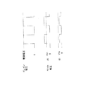
モータ駆動回路3の内部トランジスタは説明に必要な1相分についてのみ記載している。また、図4は実施の形態2の内容を補足説明する電圧波形図である。
FIG. 3 is a system configuration diagram of the motor drive apparatus according to
The internal transistor of the
図3において、トランジスタQ8内部のゲートGとドレインDの間には、半導体の構造上、寄生容量Cgdが存在している。トランジスタ駆動回路50からトランジスタQ8へ接
続される駆動信号経路にオープン故障が発生し、かつトランジスタQ8とドレインD側で接続されている上段側のトランジスタQ7がスイッチング動作を継続している場合に、トランジスタQ7の駆動により、トランジスタQ8のドレインD側に発生するスイッチングパルスが、ゲート・ドレイン間寄生容量CgdのAC結合によって、トランジスタQ8のゲ
ートG側に重畳し、ゲート・ソース間電圧がトランジスタQ8がをオンするしきい値電圧Vthを越えると、トランジスタQ8は駆動信号経路がオープンとなっているにもかかわら
ずオン状態となり、短絡電流の発生や破壊に至る場合がある。
In FIG. 3, a parasitic capacitance Cgd exists between the gate G and the drain D inside the transistor Q8 due to the semiconductor structure. When an open failure occurs in the drive signal path connected from the
しかしながらこの発明の実施の形態2によれば、図3に示すように、トランジスタQ8のゲート・ソース間にゲート・ソース間コンデンサCgsが接続されているので、ゲートG
に重畳するパルス電圧は、ドレインD側のスイッチングパルスをゲート・ドレイン間寄生容量Cgdと、ゲート・ソース間コンデンサCgsの容量でコンデンサ分圧した電圧となる。
However, according to the second embodiment of the present invention, the gate-source capacitor Cgs is connected between the gate and source of the transistor Q8 as shown in FIG.
The pulse voltage superimposed on is a voltage obtained by dividing the switching pulse on the drain D side by the gate-drain parasitic capacitance Cgd and the capacitance of the gate-source capacitor Cgs.
トランジスタQ8のドレインD側に発生するパルス電圧最大値は、電源2の電圧値であるので、電源電圧最大値とゲート・ドレイン間寄生容量Cgdに対して、ゲート・ソース間
コンデンサCgsの容量を一定以上の値に設定・接続しておくことで、トランジスタQ8の
ゲート・ソース間電圧がしきい値電圧Vthをこえてオンすることを防ぐことができる。
Since the maximum value of the pulse voltage generated on the drain D side of the transistor Q8 is the voltage value of the
図4を用いて説明すると、トランジスタQ8のドレインD側に発生しているドレイン電圧に対して、トランジスタQ8のゲートGに重畳するゲート電圧は、ゲート・ソース間コンデンサCgsが接続されない場合、または、容量が不足している場合は、A)に示すよう
に、しきい値電圧Vthを越えるが、ゲート・ソース間コンデンサCgsの容量を一定以上の値に設定・接続すると、B)に示すように、しきい値電圧Vthを越えずトランジスタQ8は
オフ状態となる。
Referring to FIG. 4, the gate voltage superimposed on the gate G of the transistor Q8 with respect to the drain voltage generated on the drain D side of the transistor Q8 is the case where the gate-source capacitor Cgs is not connected, or If the capacitance is insufficient, the threshold voltage Vth will be exceeded as shown in A), but if the capacitance of the gate-source capacitor Cgs is set and connected to a certain value or more, as shown in B) The transistor Q8 is turned off without exceeding the threshold voltage Vth.
実施の形態2では、ゲート・ソース間コンデンサCgsをトランジスタQ8の内部に配置
・接続しているため、トランジスタ駆動回路50からトランジスタQ8に入力される信号経路上にオープン故障が発生した場合であっても、ゲート・ソース間コンデンサCgsはト
ランジスタQ8と接続されたままであり、有効に目的を果たし、故障の発生した信号経路に接続されたトランジスタQ8はオフ状態となる。
In the second embodiment, since the gate-source capacitor Cgs is disposed and connected inside the transistor Q8, an open failure occurs on the signal path input from the
図5は、実施の形態2の図3に記載されているトランジスタの内部構成を説明した接続図である。
図5において、個別部品であるトランジスタQ10は、半導体チップ5を内蔵し、ボンディングワイヤ7によって、半導体チップ5上のゲート部8と、トランジスタのゲート端子6との間が接続されている。
FIG. 5 is a connection diagram illustrating the internal configuration of the transistor described in FIG. 3 according to the second embodiment.
In FIG. 5, a transistor Q10, which is an individual component, incorporates a
ゲート・ソース間コンデンサCgsを半導体チップ5上に直接形成・配置しているため、
トランスタQ10の内部の駆動信号経路であるゲート端子6と、ボンディングワイヤ7、半導体チップ5上のゲート部8においてオープン故障が発生した場合であっても、ゲート・ソース間コンデンサCgsは半導体チップ上で接続状態であるため、有効に機能を果たすことができトランジスタQ10をオフ状態とすることができる。
Since the gate-source capacitor Cgs is formed and arranged directly on the
Even when an open failure occurs in the
以上のように、この発明の実施の形態2によれば、モータ駆動回路のトランジスタ内部にゲート・ソース間コンデンサを内蔵する構成とすることによって、実施の形態1と同様に、基板上の駆動信号経路においてオープン故障が発生した場合でも、トランジスタを確実にオフ状態とすることができる。また、別部品を外部に追加する必要がなくなり、部品点数の低減、装置の小型化が可能となる。 As described above, according to the second embodiment of the present invention, the gate-source capacitor is built in the transistor of the motor drive circuit, so that the drive signal on the substrate is the same as in the first embodiment. Even when an open failure occurs in the path, the transistor can be reliably turned off. Further, it is not necessary to add another part to the outside, and the number of parts can be reduced and the apparatus can be downsized.
また、トランジスタ内部のさらに半導体チップ上にゲート・ソース間コンデンサを形成・配置する構成とすることによって、基板上の駆動信号経路に加えて、トランジスタ内部の接続部位のオープン故障が発生した場合でも、確実にオフ状態とすることができる。 In addition, in addition to the drive signal path on the substrate, by configuring the gate-source capacitor on the semiconductor chip further inside the transistor, even when an open failure of the connection site inside the transistor occurs, It can be surely turned off.
実施の形態3.
実施の形態1、2を組み合わせて、図1および図3のように、上下のアーム(トランジスタ)によって構成されるモータ駆動回路3を用いたモータ駆動装置1において使用することで、駆動信号経路のオープン故障による上下短絡時大電流を防ぐことにより、システムのモータ駆動装置および装置に接続される電源装置、電源ライン、ヒューズの過電流による故障、断線、発熱を防止し、安全性を向上することができる。
By combining the first and second embodiments and using the
実施の形態4.
上述の実施の形態1〜3で説明したモータ駆動装置1の、全体または一部の回路部分を樹脂モールド封止することによって、断線の防止や外部環境による劣化を防止し、少なくともゲート・ソース間の抵抗またはコンデンサを樹脂モールド封止することで、装置の信頼性・耐久性を向上することが可能となる。
The entire or part of the
1 モータ駆動装置、2 電源、3 モータ駆動回路、4 モータ、
5 半導体チップ、6 トランジスタゲート端子、7 ボンディングワイヤ、
8 半導体チップゲート部、50 トランジスタ駆動回路、
Q1〜Q10 スイッチングトランジスタ、
Rg1〜Rg8 ゲート抵抗、
Rgs、Rgs1〜Rgs8 ゲート・ソース間抵抗、
Cgs ゲート・ソース間コンデンサ、
Cgd ゲート・ドレイン間寄生容量、
G ゲート
D ドレイン
S ソース
Vth しきい値電圧
1 motor drive device, 2 power supply, 3 motor drive circuit, 4 motor,
5 Semiconductor chip, 6 Transistor gate terminal, 7 Bonding wire,
8 Semiconductor chip gate part, 50 transistor drive circuit,
Q1-Q10 switching transistor,
Rg1-Rg8 gate resistance,
Rgs, Rgs1 to Rgs8 Gate-source resistance,
Cgs Gate-source capacitor,
Cgd Gate-drain parasitic capacitance,
G gate D drain S source Vth threshold voltage
Claims (4)
Priority Applications (2)
| Application Number | Priority Date | Filing Date | Title |
|---|---|---|---|
| JP2010248552A JP5161949B2 (en) | 2010-11-05 | 2010-11-05 | Motor drive device |
| EP11158797.8A EP2451068B1 (en) | 2010-11-05 | 2011-03-18 | Motor drive device |
Applications Claiming Priority (1)
| Application Number | Priority Date | Filing Date | Title |
|---|---|---|---|
| JP2010248552A JP5161949B2 (en) | 2010-11-05 | 2010-11-05 | Motor drive device |
Publications (2)
| Publication Number | Publication Date |
|---|---|
| JP2012100506A JP2012100506A (en) | 2012-05-24 |
| JP5161949B2 true JP5161949B2 (en) | 2013-03-13 |
Family
ID=45688311
Family Applications (1)
| Application Number | Title | Priority Date | Filing Date |
|---|---|---|---|
| JP2010248552A Active JP5161949B2 (en) | 2010-11-05 | 2010-11-05 | Motor drive device |
Country Status (2)
| Country | Link |
|---|---|
| EP (1) | EP2451068B1 (en) |
| JP (1) | JP5161949B2 (en) |
Family Cites Families (10)
| Publication number | Priority date | Publication date | Assignee | Title |
|---|---|---|---|---|
| JPH0879036A (en) * | 1994-08-31 | 1996-03-22 | Oki Electric Ind Co Ltd | Switch circuit |
| JP2000299926A (en) * | 1999-02-12 | 2000-10-24 | Yazaki Corp | Power supply control device and method therefor |
| JP2000299924A (en) * | 1999-02-14 | 2000-10-24 | Yazaki Corp | Power supply control device and method |
| JP4547231B2 (en) * | 2004-10-22 | 2010-09-22 | 日立オートモティブシステムズ株式会社 | Power converter |
| US7660094B2 (en) * | 2004-12-14 | 2010-02-09 | Mitsubishi Denki Kabushiki Kaisha | Inverter circuit |
| JP4916860B2 (en) * | 2006-12-08 | 2012-04-18 | ルネサスエレクトロニクス株式会社 | Load driving circuit and method for manufacturing load driving circuit |
| JP2008187066A (en) * | 2007-01-31 | 2008-08-14 | Oki Electric Ind Co Ltd | Power transistor |
| JP4453776B2 (en) * | 2007-11-14 | 2010-04-21 | 株式会社デンソー | Bus switch |
| JP5315026B2 (en) * | 2008-11-28 | 2013-10-16 | ルネサスエレクトロニクス株式会社 | Semiconductor device |
| EP2549639A3 (en) * | 2010-03-11 | 2013-07-24 | Mitsubishi Electric Corporation | Power converter |
-
2010
- 2010-11-05 JP JP2010248552A patent/JP5161949B2/en active Active
-
2011
- 2011-03-18 EP EP11158797.8A patent/EP2451068B1/en active Active
Also Published As
| Publication number | Publication date |
|---|---|
| JP2012100506A (en) | 2012-05-24 |
| EP2451068A3 (en) | 2014-07-30 |
| EP2451068B1 (en) | 2020-03-11 |
| EP2451068A2 (en) | 2012-05-09 |
Similar Documents
| Publication | Publication Date | Title |
|---|---|---|
| US9887650B2 (en) | Inverter device and power steering device | |
| US8027183B2 (en) | 3-phase inverter module, motor driving apparatus using the same, and inverter integrated circuit package | |
| KR100735849B1 (en) | Power semiconductor device | |
| JP5673449B2 (en) | Semiconductor device | |
| JP5590031B2 (en) | Power supply protection circuit and motor drive device including the same | |
| JP6935437B2 (en) | Power supply | |
| US11923833B2 (en) | Switch driving device | |
| JP2007318897A (en) | Semiconductor device drive, power conversion device, motor drive, method of driving semiconductor device, method of converting power, and method of driving motor | |
| JP2007082036A (en) | Semiconductor integrated circuit device, power supply apparatus, and electric apparatus | |
| JP2009165113A (en) | Load driving device | |
| JPH09205727A (en) | Power transistor with short-circuit protection | |
| US20130088096A1 (en) | Short-circuit protection method | |
| JP2015032984A (en) | Device for driving semiconductor element, and power conversion device using the same | |
| US20140177306A1 (en) | Method for operating an electrical power rectifier, as well as an electrical power rectifier | |
| JP5953099B2 (en) | Load control and protection system, and operation and use thereof | |
| JP6107949B2 (en) | Semiconductor module | |
| WO2012043146A1 (en) | Semiconductor device | |
| JP2022016749A (en) | Switching device and power conversion device | |
| JP5161949B2 (en) | Motor drive device | |
| JP5810973B2 (en) | Switching element drive circuit | |
| JP2019022253A (en) | Semiconductor driving device, and three-phase ac inverter mounted with the same | |
| CN112075001B (en) | Motor ground protection | |
| JP2007129829A (en) | Inverter circuit apparatus | |
| JP3918778B2 (en) | Protection circuit | |
| JP7435359B2 (en) | load drive circuit |
Legal Events
| Date | Code | Title | Description |
|---|---|---|---|
| A131 | Notification of reasons for refusal |
Free format text: JAPANESE INTERMEDIATE CODE: A131 Effective date: 20120313 |
|
| A521 | Written amendment |
Free format text: JAPANESE INTERMEDIATE CODE: A523 Effective date: 20120425 |
|
| TRDD | Decision of grant or rejection written | ||
| A01 | Written decision to grant a patent or to grant a registration (utility model) |
Free format text: JAPANESE INTERMEDIATE CODE: A01 Effective date: 20121204 |
|
| A61 | First payment of annual fees (during grant procedure) |
Free format text: JAPANESE INTERMEDIATE CODE: A61 Effective date: 20121214 |
|
| R151 | Written notification of patent or utility model registration |
Ref document number: 5161949 Country of ref document: JP Free format text: JAPANESE INTERMEDIATE CODE: R151 |
|
| FPAY | Renewal fee payment (event date is renewal date of database) |
Free format text: PAYMENT UNTIL: 20151221 Year of fee payment: 3 |
|
| R250 | Receipt of annual fees |
Free format text: JAPANESE INTERMEDIATE CODE: R250 |
|
| R250 | Receipt of annual fees |
Free format text: JAPANESE INTERMEDIATE CODE: R250 |
|
| R250 | Receipt of annual fees |
Free format text: JAPANESE INTERMEDIATE CODE: R250 |
|
| R250 | Receipt of annual fees |
Free format text: JAPANESE INTERMEDIATE CODE: R250 |
|
| R250 | Receipt of annual fees |
Free format text: JAPANESE INTERMEDIATE CODE: R250 |
|
| R250 | Receipt of annual fees |
Free format text: JAPANESE INTERMEDIATE CODE: R250 |
|
| R250 | Receipt of annual fees |
Free format text: JAPANESE INTERMEDIATE CODE: R250 |
|
| R250 | Receipt of annual fees |
Free format text: JAPANESE INTERMEDIATE CODE: R250 |