JP5161572B2 - Solid oxide fuel cell system - Google Patents
Solid oxide fuel cell system Download PDFInfo
- Publication number
- JP5161572B2 JP5161572B2 JP2007531404A JP2007531404A JP5161572B2 JP 5161572 B2 JP5161572 B2 JP 5161572B2 JP 2007531404 A JP2007531404 A JP 2007531404A JP 2007531404 A JP2007531404 A JP 2007531404A JP 5161572 B2 JP5161572 B2 JP 5161572B2
- Authority
- JP
- Japan
- Prior art keywords
- fuel cell
- plate
- solid oxide
- cell system
- central support
- Prior art date
- Legal status (The legal status is an assumption and is not a legal conclusion. Google has not performed a legal analysis and makes no representation as to the accuracy of the status listed.)
- Active
Links
- 239000000446 fuel Substances 0.000 title claims abstract description 266
- 239000007787 solid Substances 0.000 title claims abstract description 33
- 239000004020 conductor Substances 0.000 claims description 20
- 238000002347 injection Methods 0.000 claims description 16
- 239000007924 injection Substances 0.000 claims description 16
- 239000003054 catalyst Substances 0.000 claims description 13
- 238000002485 combustion reaction Methods 0.000 claims description 10
- 239000003792 electrolyte Substances 0.000 claims description 9
- 238000007789 sealing Methods 0.000 claims description 9
- 239000012212 insulator Substances 0.000 claims description 5
- ATUOYWHBWRKTHZ-UHFFFAOYSA-N Propane Chemical compound CCC ATUOYWHBWRKTHZ-UHFFFAOYSA-N 0.000 description 14
- 239000007789 gas Substances 0.000 description 13
- PNEYBMLMFCGWSK-UHFFFAOYSA-N aluminium oxide Inorganic materials [O-2].[O-2].[O-2].[Al+3].[Al+3] PNEYBMLMFCGWSK-UHFFFAOYSA-N 0.000 description 12
- 239000001294 propane Substances 0.000 description 7
- 230000035882 stress Effects 0.000 description 7
- 238000000034 method Methods 0.000 description 5
- QVGXLLKOCUKJST-UHFFFAOYSA-N atomic oxygen Chemical compound [O] QVGXLLKOCUKJST-UHFFFAOYSA-N 0.000 description 4
- 239000011230 binding agent Substances 0.000 description 4
- 229910052739 hydrogen Inorganic materials 0.000 description 4
- 238000009413 insulation Methods 0.000 description 4
- 239000001301 oxygen Substances 0.000 description 4
- 229910052760 oxygen Inorganic materials 0.000 description 4
- 230000008646 thermal stress Effects 0.000 description 4
- 239000000919 ceramic Substances 0.000 description 3
- 238000006243 chemical reaction Methods 0.000 description 3
- 230000005611 electricity Effects 0.000 description 3
- 239000001257 hydrogen Substances 0.000 description 3
- 150000002500 ions Chemical class 0.000 description 3
- 238000012423 maintenance Methods 0.000 description 3
- 239000000126 substance Substances 0.000 description 3
- 229910018072 Al 2 O 3 Inorganic materials 0.000 description 2
- UFHFLCQGNIYNRP-UHFFFAOYSA-N Hydrogen Chemical compound [H][H] UFHFLCQGNIYNRP-UHFFFAOYSA-N 0.000 description 2
- BQCADISMDOOEFD-UHFFFAOYSA-N Silver Chemical compound [Ag] BQCADISMDOOEFD-UHFFFAOYSA-N 0.000 description 2
- 239000010405 anode material Substances 0.000 description 2
- 229910002091 carbon monoxide Inorganic materials 0.000 description 2
- 229910010293 ceramic material Inorganic materials 0.000 description 2
- 239000011195 cermet Substances 0.000 description 2
- 230000008859 change Effects 0.000 description 2
- 238000003487 electrochemical reaction Methods 0.000 description 2
- 239000000945 filler Substances 0.000 description 2
- 239000006260 foam Substances 0.000 description 2
- 239000000463 material Substances 0.000 description 2
- 230000007246 mechanism Effects 0.000 description 2
- 239000000203 mixture Substances 0.000 description 2
- 230000003647 oxidation Effects 0.000 description 2
- 238000007254 oxidation reaction Methods 0.000 description 2
- 238000005381 potential energy Methods 0.000 description 2
- 238000010248 power generation Methods 0.000 description 2
- 230000008569 process Effects 0.000 description 2
- 238000002407 reforming Methods 0.000 description 2
- UGFAIRIUMAVXCW-UHFFFAOYSA-N Carbon monoxide Chemical compound [O+]#[C-] UGFAIRIUMAVXCW-UHFFFAOYSA-N 0.000 description 1
- 239000006091 Macor Substances 0.000 description 1
- 229910019017 PtRh Inorganic materials 0.000 description 1
- 238000005266 casting Methods 0.000 description 1
- 238000004581 coalescence Methods 0.000 description 1
- 230000006835 compression Effects 0.000 description 1
- 238000007906 compression Methods 0.000 description 1
- 230000008878 coupling Effects 0.000 description 1
- 238000010168 coupling process Methods 0.000 description 1
- 238000005859 coupling reaction Methods 0.000 description 1
- 230000000694 effects Effects 0.000 description 1
- 239000000284 extract Substances 0.000 description 1
- 239000000835 fiber Substances 0.000 description 1
- 239000011094 fiberboard Substances 0.000 description 1
- 150000002431 hydrogen Chemical class 0.000 description 1
- 230000000977 initiatory effect Effects 0.000 description 1
- 238000003780 insertion Methods 0.000 description 1
- 230000037431 insertion Effects 0.000 description 1
- 239000011810 insulating material Substances 0.000 description 1
- 230000003993 interaction Effects 0.000 description 1
- 239000012528 membrane Substances 0.000 description 1
- 229910052751 metal Inorganic materials 0.000 description 1
- 239000002184 metal Substances 0.000 description 1
- 239000002245 particle Substances 0.000 description 1
- 239000008188 pellet Substances 0.000 description 1
- 238000006057 reforming reaction Methods 0.000 description 1
- 229910052594 sapphire Inorganic materials 0.000 description 1
- 239000010980 sapphire Substances 0.000 description 1
- 229910052709 silver Inorganic materials 0.000 description 1
- 239000004332 silver Substances 0.000 description 1
- 238000009423 ventilation Methods 0.000 description 1
Images


Classifications
-
- H—ELECTRICITY
- H01—ELECTRIC ELEMENTS
- H01M—PROCESSES OR MEANS, e.g. BATTERIES, FOR THE DIRECT CONVERSION OF CHEMICAL ENERGY INTO ELECTRICAL ENERGY
- H01M8/00—Fuel cells; Manufacture thereof
- H01M8/04—Auxiliary arrangements, e.g. for control of pressure or for circulation of fluids
-
- H—ELECTRICITY
- H01—ELECTRIC ELEMENTS
- H01M—PROCESSES OR MEANS, e.g. BATTERIES, FOR THE DIRECT CONVERSION OF CHEMICAL ENERGY INTO ELECTRICAL ENERGY
- H01M8/00—Fuel cells; Manufacture thereof
- H01M8/02—Details
- H01M8/0271—Sealing or supporting means around electrodes, matrices or membranes
- H01M8/0273—Sealing or supporting means around electrodes, matrices or membranes with sealing or supporting means in the form of a frame
-
- H—ELECTRICITY
- H01—ELECTRIC ELEMENTS
- H01M—PROCESSES OR MEANS, e.g. BATTERIES, FOR THE DIRECT CONVERSION OF CHEMICAL ENERGY INTO ELECTRICAL ENERGY
- H01M8/00—Fuel cells; Manufacture thereof
- H01M8/06—Combination of fuel cells with means for production of reactants or for treatment of residues
- H01M8/0606—Combination of fuel cells with means for production of reactants or for treatment of residues with means for production of gaseous reactants
- H01M8/0612—Combination of fuel cells with means for production of reactants or for treatment of residues with means for production of gaseous reactants from carbon-containing material
- H01M8/0625—Combination of fuel cells with means for production of reactants or for treatment of residues with means for production of gaseous reactants from carbon-containing material in a modular combined reactor/fuel cell structure
-
- H—ELECTRICITY
- H01—ELECTRIC ELEMENTS
- H01M—PROCESSES OR MEANS, e.g. BATTERIES, FOR THE DIRECT CONVERSION OF CHEMICAL ENERGY INTO ELECTRICAL ENERGY
- H01M8/00—Fuel cells; Manufacture thereof
- H01M8/10—Fuel cells with solid electrolytes
- H01M8/12—Fuel cells with solid electrolytes operating at high temperature, e.g. with stabilised ZrO2 electrolyte
-
- H—ELECTRICITY
- H01—ELECTRIC ELEMENTS
- H01M—PROCESSES OR MEANS, e.g. BATTERIES, FOR THE DIRECT CONVERSION OF CHEMICAL ENERGY INTO ELECTRICAL ENERGY
- H01M8/00—Fuel cells; Manufacture thereof
- H01M8/24—Grouping of fuel cells, e.g. stacking of fuel cells
- H01M8/241—Grouping of fuel cells, e.g. stacking of fuel cells with solid or matrix-supported electrolytes
- H01M8/2425—High-temperature cells with solid electrolytes
- H01M8/243—Grouping of unit cells of tubular or cylindrical configuration
-
- H—ELECTRICITY
- H01—ELECTRIC ELEMENTS
- H01M—PROCESSES OR MEANS, e.g. BATTERIES, FOR THE DIRECT CONVERSION OF CHEMICAL ENERGY INTO ELECTRICAL ENERGY
- H01M8/00—Fuel cells; Manufacture thereof
- H01M8/24—Grouping of fuel cells, e.g. stacking of fuel cells
- H01M8/2465—Details of groupings of fuel cells
- H01M8/2484—Details of groupings of fuel cells characterised by external manifolds
- H01M8/2485—Arrangements for sealing external manifolds; Arrangements for mounting external manifolds around a stack
-
- H—ELECTRICITY
- H01—ELECTRIC ELEMENTS
- H01M—PROCESSES OR MEANS, e.g. BATTERIES, FOR THE DIRECT CONVERSION OF CHEMICAL ENERGY INTO ELECTRICAL ENERGY
- H01M8/00—Fuel cells; Manufacture thereof
- H01M8/02—Details
- H01M8/0202—Collectors; Separators, e.g. bipolar separators; Interconnectors
- H01M8/0247—Collectors; Separators, e.g. bipolar separators; Interconnectors characterised by the form
-
- H—ELECTRICITY
- H01—ELECTRIC ELEMENTS
- H01M—PROCESSES OR MEANS, e.g. BATTERIES, FOR THE DIRECT CONVERSION OF CHEMICAL ENERGY INTO ELECTRICAL ENERGY
- H01M8/00—Fuel cells; Manufacture thereof
- H01M8/04—Auxiliary arrangements, e.g. for control of pressure or for circulation of fluids
- H01M8/04007—Auxiliary arrangements, e.g. for control of pressure or for circulation of fluids related to heat exchange
- H01M8/04067—Heat exchange or temperature measuring elements, thermal insulation, e.g. heat pipes, heat pumps, fins
-
- Y—GENERAL TAGGING OF NEW TECHNOLOGICAL DEVELOPMENTS; GENERAL TAGGING OF CROSS-SECTIONAL TECHNOLOGIES SPANNING OVER SEVERAL SECTIONS OF THE IPC; TECHNICAL SUBJECTS COVERED BY FORMER USPC CROSS-REFERENCE ART COLLECTIONS [XRACs] AND DIGESTS
- Y02—TECHNOLOGIES OR APPLICATIONS FOR MITIGATION OR ADAPTATION AGAINST CLIMATE CHANGE
- Y02E—REDUCTION OF GREENHOUSE GAS [GHG] EMISSIONS, RELATED TO ENERGY GENERATION, TRANSMISSION OR DISTRIBUTION
- Y02E60/00—Enabling technologies; Technologies with a potential or indirect contribution to GHG emissions mitigation
- Y02E60/30—Hydrogen technology
- Y02E60/50—Fuel cells
Landscapes
- Life Sciences & Earth Sciences (AREA)
- Engineering & Computer Science (AREA)
- Manufacturing & Machinery (AREA)
- Sustainable Development (AREA)
- Sustainable Energy (AREA)
- Chemical & Material Sciences (AREA)
- Chemical Kinetics & Catalysis (AREA)
- Electrochemistry (AREA)
- General Chemical & Material Sciences (AREA)
- Fuel Cell (AREA)
- Catalysts (AREA)
Abstract
Description
発明の分野
本発明は、新規燃料電池システムに関連する。より詳しくは、本発明は、固体酸化物型燃料電池システムに関連する。
The present invention relates to a novel fuel cell system. More particularly, the present invention relates to a solid oxide fuel cell system.
発明の背景
燃料電池は、電気化学反応を通して、燃料の電位エネルギーを電気に変換する電気装置である。一般に、燃料電池は、電解質により分割された一対の電極を備える。電解質は、あるタイプのイオンの通過のみ可能にする。電解質を介したイオンの選択的通過により、2つの電極間に電位が生じることになる。この電位は、自動車または家電機器に電力供給するなどの、有用な仕事に役立てることができる。この直接的な変換処理は、タービン装置などの、従来の発電装置に要求される機械的ステップを排除することにより、発電効率を増加させる。さらに、より高効率および電気化学的な過程の組み合わせにより、環境に優しい製品が得られる。
BACKGROUND OF THE INVENTION A fuel cell is an electrical device that converts the potential energy of a fuel into electricity through an electrochemical reaction. In general, a fuel cell includes a pair of electrodes divided by an electrolyte. The electrolyte only allows the passage of certain types of ions. The selective passage of ions through the electrolyte creates a potential between the two electrodes. This potential can be useful for useful work such as powering a car or home appliance. This direct conversion process increases power generation efficiency by eliminating the mechanical steps required for conventional power generation equipment, such as turbine equipment. In addition, a combination of higher efficiency and electrochemical processes results in environmentally friendly products.
固体酸化物型燃料電池(「SOFC」)は、電気化学反応を通して、燃料の電位エネルギーを電気に変換する効率が約40%である装置である。SOFCは、電子を生産する陽極と、電子を消費する陰極と、イオンを伝導するが、電子を通過させない電解質との3つの基本部分を有する。多くの燃料電池とは異なり、SOFCは、別個の化学改質装置なしに多形態の燃料(例、水素、プロパン、およびディーゼル)で作動することができる。従って、SOFCシステムは、プロトン交換膜燃料電池を組み込んだシステムなどの、競合する燃料電池システムよりも1ポンドあたりより多くの電気量を生成する。 A solid oxide fuel cell (“SOFC”) is a device that is about 40% efficient in converting the potential energy of a fuel into electricity through an electrochemical reaction. The SOFC has three basic parts: an anode that produces electrons, a cathode that consumes electrons, and an electrolyte that conducts ions but does not pass electrons. Unlike many fuel cells, SOFCs can operate on polymorphic fuels (eg, hydrogen, propane, and diesel) without a separate chemical reformer. Thus, SOFC systems produce more electricity per pound than competing fuel cell systems, such as systems incorporating proton exchange membrane fuel cells.
SOFCには、燃料電池の形が円筒か平板かにより、それぞれのチューブ状電池および平面電池の2つの一般構造様式がある。固体酸化物型燃料電池は、摂氏約850〜1000度という比較的高温で操作される。この高実用温度の結果として、平面電池には、電池のセラミック部品の周辺を密封する問題がある。従って、生成する内部熱応力を低く、それに伴い密封要件を削減する、改良された燃料電池システムの必要性がある。 In SOFC, there are two general types of structures: tubular and flat cells, depending on whether the fuel cell is cylindrical or flat. Solid oxide fuel cells are operated at relatively high temperatures of about 850 to 1000 degrees Celsius. As a result of this high operating temperature, planar batteries have the problem of sealing around the ceramic parts of the battery. Accordingly, there is a need for an improved fuel cell system that produces low internal thermal stresses and concomitantly reduces sealing requirements.
発明の開示
本発明は、中央支持手段と、固定手段と、電流収集手段と、少なくとも1つの燃料電池手段とを備え、前記燃料電池手段および電流収集手段は、前記燃料電池手段の軸と平行方向に移動可能である、固体酸化物型燃料電池システムを供給する。
DISCLOSURE OF THE INVENTION The present invention comprises a central support means, a fixing means, a current collecting means, and at least one fuel cell means, wherein the fuel cell means and the current collecting means are parallel to the axis of the fuel cell means. A solid oxide fuel cell system is provided.
一側面では、燃料電池手段、例えば、燃料電池管は、電流収集手段に導電体(例、導体ペースト)などを通してしっかりと取り付けられ、単一ユニットとして移動可能なアセンブリを形成する。一実施態様では、前記燃料電池手段は、前記固定手段、例えば、注入ピン(7)の表面から延長される特徴に装着し、いわば、前記燃料電池手段および前記固定手段の表面から延長される特徴の間のすき間が、前記燃料電池手段および固定手段の間を密閉しないで操作可能となるのに十分小型となるようになっている。その他の実施態様では、前記燃料電池手段を、前記固定手段内の空洞に挿入する。前記電解質および陰極の長さは、電流収集を促進するための目的で、陽極の暴露を形成するために周辺に可変である。前記燃料電池システムの中央支持手段は、また、燃料改質装置として機能することができる。 In one aspect, the fuel cell means, eg, fuel cell tube, is securely attached to the current collection means through a conductor (eg, conductor paste) or the like to form a movable assembly as a single unit. In one embodiment, the fuel cell means is mounted on a feature extending from the surface of the fixing means, eg, the injection pin (7), so to speak, extended from the surfaces of the fuel cell means and the fixing means. The gap between the fuel cell means and the fixing means is small enough to be operated without sealing between the fuel cell means and the fixing means. In another embodiment, the fuel cell means is inserted into a cavity in the fixing means. The lengths of the electrolyte and cathode are variable in the periphery to form the anode exposure for the purpose of facilitating current collection. The central support means of the fuel cell system can also function as a fuel reformer.
前記燃料電池システムは、半球体ドーム型状のマニホルドなどのマニホルド、熱交換手段、または、再燃焼装置をさらに備えてもよい。前記熱交換手段は、いくつかの機械的手段により、前記中央支持手段に結合または連結することができる。前記熱交換手段および前記中央支持手段はまた、単一ユニットとして製造または組み立ててもよい。 The fuel cell system may further include a manifold such as a hemispherical dome-shaped manifold, a heat exchange means, or a recombustion device. The heat exchange means can be coupled or connected to the central support means by several mechanical means. The heat exchange means and the central support means may also be manufactured or assembled as a single unit.
本発明はまた、中央支持管と、燃料電池板と、電流収集板と、マニホルドと、少なくとも1つの燃料電池管とを備え、前記少なくとも1つの燃料電池管および前記電流収集板は、前記燃料電池管の軸と平行方向に自由に移動可能である、固体酸化物型燃料電池システムを提供する。 The present invention also includes a central support tube, a fuel cell plate, a current collecting plate, a manifold, and at least one fuel cell tube, wherein the at least one fuel cell tube and the current collecting plate are the fuel cell. Provided is a solid oxide fuel cell system which is freely movable in a direction parallel to a tube axis.
本発明は、さらに固体酸化物型燃料電池システムに前記燃料および他の材料(例、空気)を導入するステップを備え、前記固体酸化物型燃料電池システムは、中央支持手段と、固定手段と、電流収集手段と、少なくとも1つの燃料電池手段とを備え、前記少なくとも1つの燃料電池手段および前記電流収集手段は、前記燃料電池手段の軸と平行方向に自由に移動可能である、燃料を電気エネルギーに変換する方法を説明する。 The present invention further comprises the step of introducing the fuel and other materials (e.g., air) into the solid oxide fuel cell system, the solid oxide fuel cell system comprising a central support means, a fixing means, Electric current collecting means and at least one fuel cell means, wherein the at least one fuel cell means and the current collecting means are free to move in a direction parallel to an axis of the fuel cell means, The method of converting to will be described.
本発明のさらなる側面は、続く説明を考慮して明白となる。 Further aspects of the invention will be apparent in view of the description that follows.
(発明の詳細な説明)
本明細書および添付の特許請求の範囲において、文脈により明白に別途指示されていない限り、単数形は、複数についての言及も含む。従って、例えば、「燃焼触媒」を参照という場合は、そのような複数の燃焼触媒を含み、「燃料電池管」を参照ということは、1つ以上の燃料電池管および当業者には既知である同等物を指す。本明細書に記載されるすべての公開、特許出願、特許、また他の文献は、参照することによりその全体が組み込まれる。
(Detailed description of the invention)
In this specification and the appended claims, the singular forms also include a reference to the plural unless the context clearly dictates otherwise. Thus, for example, reference to “a combustion catalyst” includes a plurality of such combustion catalysts, and reference to “a fuel cell tube” is known to one or more fuel cell tubes and those skilled in the art. Refers to the equivalent. All publications, patent applications, patents, and other references mentioned herein are incorporated by reference in their entirety.
本発明は、中央支持管と、燃料電池板と、電流収集板と、複数の燃料電池管と、選択的にマニホルドと、絶縁手段と、熱交換器または再燃焼装置とを備える、燃料電池システムを供給する。一実施態様では、熱サイクルシステムの開始および終了に関連している間、燃料電池システムの設計は、燃料電池管を無制限に拡張および収縮することができ、それによって、固体酸化物型燃料電池の初期故障を生じる熱応力を削減または排除する。さらに、燃料電池システムは、燃料改質装置や熱交換器と同様に燃料電池管も、保守または交換のために容易に取り外すことができるように設計されている。 The present invention provides a fuel cell system comprising a central support tube, a fuel cell plate, a current collecting plate, a plurality of fuel cell tubes, optionally a manifold, an insulating means, and a heat exchanger or recombustion device. Supply. In one embodiment, the fuel cell system design can expand and contract the fuel cell tube indefinitely while associated with the initiation and termination of the thermal cycle system, thereby enabling the solid oxide fuel cell Reduce or eliminate thermal stresses that cause initial failure. Further, the fuel cell system is designed so that the fuel cell tube as well as the fuel reformer and the heat exchanger can be easily removed for maintenance or replacement.
中央支持管(2)と、燃料電池板(4)と、電流収集板(5)を、例えば、セラミック材などのSOFCシステムに適した材質で作ることができる。中央支持管(2)は、抵抗または機械的相互作用などの多くの作用を通して、燃料電池板(4)に接続することができる。図1は、チューブ状固体酸化物型燃料電池システム設計を公開し、中央支持管(2)を、単なる抵抗により、燃料電池板(4)に装着する。中央支持管(2)および燃料電池板(4)の接続は、抵抗が中央改質管の定位置にある燃料電池板(4)を保持するように、堅固なスリップのかみ合いであってよい。 The central support tube (2), the fuel cell plate (4), and the current collecting plate (5) can be made of a material suitable for the SOFC system such as a ceramic material. The central support tube (2) can be connected to the fuel cell plate (4) through many actions such as resistance or mechanical interaction. FIG. 1 discloses a tubular solid oxide fuel cell system design where a central support tube (2) is attached to a fuel cell plate (4) by simple resistance. The connection between the central support tube (2) and the fuel cell plate (4) may be a firm slip engagement so that the resistance holds the fuel cell plate (4) in place in the central reforming tube.
中央支持管(2)はまた、燃料(例、プロパン)を固体酸化物型燃料電池による反応に適した一酸化炭素および水素に変換するための、一体化した改質装置として機能させることができる。好適な実施態様では、改質装置は部分酸化改質装置である。例えば、プロパンが燃料として使用される場合、部分酸化改質装置がCOおよびH2に変換する。 The central support tube (2) can also function as an integrated reformer to convert fuel (eg, propane) into carbon monoxide and hydrogen suitable for reaction by a solid oxide fuel cell. . In a preferred embodiment, the reformer is a partial oxidation reformer. For example, when propane is used as fuel, the partial oxidation reformer converts into CO and H 2.
C3H8+1.5O2 → 3CO+4H2
一実施態様では、燃料電池(3)は、図2で示されるように、注入ピン(7)と称する燃料電池板(4)の特徴に装着する。注入ピン(7)は、燃料電池板(4)の一体型の特徴として形成されるか、もしくは、別個に製造され、燃料電池板(4)に備え付けられてもよい。燃料電池管(3)の直径は、燃料電池管(3)を注入ピン(7)に備え付ける場合、狭いすき間を形成するように、注入ピン(7)の直径よりもわずかに大きくてもよい。注入ピン(7)および燃料電池(3)の内部間の狭いすき間を通る圧力降下は、燃料電池室を通る圧力降下よりもはるかに高いため、リフォーメート(ガス燃料)漏れを防ぐ種の別個の密閉は必要なく、従って、別個の密閉の使用なしに燃料電池管(3)の内部からリフォーメート(ガス燃料)の漏れを最小限にする十分な逆圧がある。例えば、2.8mmの直径を備える燃料電池(3)を、2.5〜2.7mmの直径を備える注入ピン(7)に備え付ける。従って、形成されたすき間は、燃料電池システムの操作を妨げない。他の実施態様では、図5に示されるように、燃料電池板(4)内の空洞(8)に挿入することにより、燃料電池(3)を燃料電池板に備え付ける。空洞(8)の直径は、燃料電池管(3)の直径と同等またはわずかに小さくてもよい。
C 3 H 8 + 1.5O 2 → 3CO + 4H 2
In one embodiment, the fuel cell (3) is mounted on a feature of the fuel cell plate (4), referred to as the injection pin (7), as shown in FIG. The injection pin (7) may be formed as an integral feature of the fuel cell plate (4), or may be manufactured separately and attached to the fuel cell plate (4). The diameter of the fuel cell tube (3) may be slightly larger than the diameter of the injection pin (7) so as to form a narrow gap when the fuel cell tube (3) is attached to the injection pin (7). Since the pressure drop through the narrow gap between the injection pin (7) and the interior of the fuel cell (3) is much higher than the pressure drop through the fuel cell chamber, a separate type of species that prevents reformate (gas fuel) leakage. There is no need for a seal, so there is sufficient back pressure to minimize the leakage of reformate (gas fuel) from inside the fuel cell tube (3) without the use of a separate seal. For example, a fuel cell (3) with a diameter of 2.8 mm is mounted on an injection pin (7) with a diameter of 2.5 to 2.7 mm. Therefore, the formed gap does not disturb the operation of the fuel cell system. In another embodiment, as shown in FIG. 5, the fuel cell (3) is mounted on the fuel cell plate by insertion into a cavity (8) in the fuel cell plate (4). The diameter of the cavity (8) may be equal to or slightly smaller than the diameter of the fuel cell tube (3).
狭いすき間を通る圧力降下をさらに増加するために、絶縁体で作られた板(10)などの絶縁手段を、図6に示されるように、燃料電池板(4)に近接して備え付けることができる。ここで使用される「近接して」の用語は、状態に言及し、隣接した部品の間のすき間がない場合、または2つの隣接した部品の間のすき間がある場合であっても、すき間は部品の機能を妨げないように十分小さいことであり、この場合は、ガス漏れを最小限にするための逆圧を作成することである。絶縁板(10)は、燃料漏れの際には漏れた燃料をCO2に変換する燃焼触媒を含み、従って、燃料電池管(3)の導管外に非還元環境を維持することに役立つ。 In order to further increase the pressure drop through the narrow gap, an insulating means such as a plate (10) made of an insulator may be provided close to the fuel cell plate (4), as shown in FIG. it can. As used herein, the term “in close proximity” refers to a condition, where there is no gap between adjacent parts, or even if there is a gap between two adjacent parts. It is small enough so as not to disturb the function of the part, in this case creating a back pressure to minimize gas leakage. Insulating plate (10), a fuel leak in the fuel leakage include combustion catalyst to convert CO 2, thus, it helps to maintain a non-reducing environment in the conduit outside of the fuel cell tube (3).
同様に、中央支持管(2)および燃料電池板(4)、そして選択的に絶縁板(10)の間の狭いすき間は、別個の密閉を使用することなしに2つの部品間のすき間を通るリフォーメートの漏れを防ぐ。 Similarly, the narrow gap between the central support tube (2) and the fuel cell plate (4) and optionally the insulation plate (10) passes through the gap between the two parts without using a separate seal. Prevent reformate leakage.
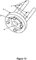
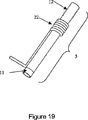
図1に示されるように、燃料電池(3)を電流収集板(5)に接続する。一実施態様では、好ましい出力電圧を生成するために、並列接続および直列接続の適切な合成を備える燃料電池(3)を相互接続する電流収集システムにより、各電池を電気的に電流収集板(5)に接続する。多機構を、電流収集の機能を果たすために使用できる。一実施態様では、図7〜10および21〜23に示されるように、陰極および陽極が特異的パターンで露出する方法で、燃料電池管(3)を加工し、燃料電池(3)を適切な位置に電流収集板(5)に挿入する場合、要望どおり、隣接した燃料電池(3)の陽極または陰極を相互接続するための導体ペーストまたはクリップの利用できるように、パターンを適切に位置付ける。例えば、図10に示されるように、燃料電池(3)を相互接続するための導体ペーストの利用機能を果たすために、図9に示されるように、機能低下パターンを燃料電池板(4)に内蔵することができる。燃料電池(3)を電流収集板(5)内の対応する機能と協調する、局部平面、突起部、または溝を含んで加工し、電流収集板(5)を備える燃料電池陰極および陽極パターンの適切な位置付けを保証する。あるいは、図7〜8に示されるように、陽極(11)が部分的に半円パターン(26)に露出するように、燃料電池(3)を製造することができる。図21〜23に示されるように、燃料電池(3)および導体クリップ(27)を電流収集板(5)に挿入する場合、導体クリップ(27)を燃料電池(3)に相互接続するのに使用する。隣接した燃料電池(3)に対し、導体クリップの一方の末端を陽極(11)に接触させ、導体クリップ(27)のもう一方の末端を陰極(12)に接触させる要件に適合するために、燃料電池(3)が取り付けられる電流収集板(5)の穴の隣に陽極クリップ溝(29)および陰極クリップ溝(28)が設けられる。セラミックフィラー(32)を、導体クリップ(27)および陰極パワークリップ(31)が開放回路または短絡回路に通じる移動を防ぐために陰極クリップ溝に設置する(図23)。燃料電池管(3)からの電流収集は、個々の燃料電池(3)の陽極および陰極に相互接続するように、ワイヤー(例、銀線)または他の適切な手段を使用して達成されてもよい。図の19〜20は、他の電流収集計画を開示し、陰極電流収集(22)は、燃料電池(3)の周辺に堅く巻きつけられて、電流収集板(5)の穴をくぐり抜けたワイヤーにより提供される。電池末端近くの燃料電池(3)の陽極(11)は、燃料電池(3)が電流収集板に挿入された後、電流収集できるよう露出される。次いでワイヤーは、隣接した燃料電池(3)の末端に露出した陽極材料の周辺に巻きつけられ、陽極電流収集(23)を形成する。隣接した燃料電池(3)の陽極と陰極を接続することにより、燃料電池(3)は直列に電気的配線される。システムの陰極(12)および陽極(11)のそれぞれに接続されたリード線(24)および(25)により、燃料電池(3)によって生成された電力が、システムから引き出される。 As shown in FIG. 1, the fuel cell (3) is connected to the current collecting plate (5). In one embodiment, each cell is electrically connected to a current collector plate (5) by a current collection system that interconnects the fuel cells (3) with a suitable combination of parallel and series connections to produce a preferred output voltage. ). Multiple mechanisms can be used to perform the function of current collection. In one embodiment, as shown in FIGS. 7-10 and 21-23, the fuel cell tube (3) is processed in a manner in which the cathode and anode are exposed in a specific pattern, and the fuel cell (3) is When inserted into the current collecting plate (5) in position, the pattern is properly positioned so that conductor paste or clips can be utilized to interconnect the anodes or cathodes of adjacent fuel cells (3) as desired. For example, as shown in FIG. 10, in order to perform the use function of the conductive paste for interconnecting the fuel cells (3), as shown in FIG. 9, the reduced function pattern is applied to the fuel cell plate (4). Can be built in. A fuel cell cathode and anode pattern comprising a current collecting plate (5), wherein the fuel cell (3) is processed to include local planes, protrusions or grooves, cooperating with corresponding functions in the current collecting plate (5). Ensure proper positioning. Alternatively, as shown in FIGS. 7 to 8, the fuel cell (3) can be manufactured such that the anode (11) is partially exposed to the semicircular pattern (26). As shown in FIGS. 21 to 23, when the fuel cell (3) and the conductor clip (27) are inserted into the current collecting plate (5), the conductor clip (27) is interconnected to the fuel cell (3). use. In order to meet the requirement for an adjacent fuel cell (3) that one end of the conductor clip is in contact with the anode (11) and the other end of the conductor clip (27) is in contact with the cathode (12), An anode clip groove (29) and a cathode clip groove (28) are provided next to the holes of the current collecting plate (5) to which the fuel cell (3) is attached. A ceramic filler (32) is placed in the cathode clip groove to prevent the conductor clip (27) and the cathode power clip (31) from moving to the open or short circuit (FIG. 23). Current collection from the fuel cell tube (3) is accomplished using wires (eg, silver wire) or other suitable means to interconnect to the anode and cathode of the individual fuel cell (3). Also good. 19-20 of the figure disclose another current collection scheme, where the cathode current collection (22) is tightly wrapped around the periphery of the fuel cell (3) and passes through the holes in the current collection plate (5). Provided by. The anode (11) of the fuel cell (3) near the end of the cell is exposed for current collection after the fuel cell (3) is inserted into the current collection plate. The wire is then wound around the anode material exposed at the end of the adjacent fuel cell (3) to form the anode current collection (23). By connecting the anode and cathode of the adjacent fuel cell (3), the fuel cell (3) is electrically wired in series. Leads (24) and (25) connected to the cathode (12) and anode (11), respectively, of the system draw power generated by the fuel cell (3) from the system.
一実施態様では、電流収集板(5)は、中央支持管(2)に適合したスリップであり、燃料電池管(3)の軸と平行方向に移動可能である。ここで使用される「移動可能」の用語は、電流収集板(5)や中央支持管(2)などの2つの対象物の間の相対的な位置の変化を指す。また、一方の対象物の一部(例、燃料電池(3)の陽極(11)末端のような燃料電池管(3)の延長した、または縮めた一部)と、他方の対象物(例、中央支持管(2))との間の相対的な位置の変化を指す。電流収集板(5)および燃料電池(3)の合体は、中央支持管(2)に沿ってはめることができる。燃料電池システムの操作中、電流収集板/燃料電池アセンブリを中央支持管(2)および電流収集板(5)の間の空間距離の結果として、縦方向に延長する。この移動の自由は、燃料電池(3)に適応する縦方向の圧縮力を最小限にする。 In one embodiment, the current collecting plate (5) is a slip adapted to the central support tube (2) and is movable in a direction parallel to the axis of the fuel cell tube (3). The term “movable” as used herein refers to a change in the relative position between two objects such as a current collecting plate (5) and a central support tube (2). Also, a part of one object (eg, an extended or contracted part of the fuel cell tube (3) such as the end of the anode (11) of the fuel cell (3)) and the other object (eg, , Refers to the change in relative position between the central support tube (2)). The coalescence of the current collecting plate (5) and the fuel cell (3) can be fitted along the central support tube (2). During operation of the fuel cell system, the current collection plate / fuel cell assembly is extended longitudinally as a result of the spatial distance between the central support tube (2) and the current collection plate (5). This freedom of movement minimizes the longitudinal compression force that accommodates the fuel cell (3).
一実施態様では、図3に示されるように、中央支持管(2)に簡単にはめるため、電流収集および燃料電池アセンブリを整備および交換のためにスタックから容易に取り外すことができる。他の実施態様では、図4に示されるように、燃料電池板(4)への堅固なスリップかみ合い(抵抗かみ合い)であるため、中央支持管(2)を容易にスタックから取り外すことができる。 In one embodiment, as shown in FIG. 3, the current collection and fuel cell assembly can be easily removed from the stack for servicing and replacement in order to fit easily into the central support tube (2). In another embodiment, as shown in FIG. 4, the central support tube (2) can be easily removed from the stack due to the firm slip engagement (resistance engagement) to the fuel cell plate (4).
燃料電池板(4)の代替設計は、図5に示されるように、板は、通常、アルミナまたは類似のセラミック材で作られ、例えば、2〜8ミクロンのアルミナファイバーの、絶縁材を使用して前記板を構築する。この設計では、燃料電池板(4)に中央支持管(2)を挿入する深さがより大きくなるため、中央支持管(2)および燃料電池板(4)の間のすき間は、より大きくなり、燃料電池管(3)の内部および燃料電池管(3)周囲のエリア間に大きな圧力降下が起こり、従ってガス漏れを最小限にする。 An alternative design for the fuel cell plate (4), as shown in FIG. 5, is typically made of alumina or a similar ceramic material and uses an insulating material, eg, 2-8 micron alumina fiber. To build the plate. In this design, the depth at which the central support tube (2) is inserted into the fuel cell plate (4) is greater, so the gap between the central support tube (2) and the fuel cell plate (4) is greater. A large pressure drop occurs between the interior of the fuel cell tube (3) and the area around the fuel cell tube (3), thus minimizing gas leakage.
一実施態様では、図6に示されるように、絶縁板(10)は、燃料電池板(4)に近接して位置する。燃料電池管(3)が絶縁板を通過する穴は、燃料電池(3)および絶縁板の間に堅固なかみ合いをもたらす個々の燃料電池管(3)より同等またはわずかに小さい直径で加工することができる。絶縁板(10)をアルミナ結合材または抵抗などの化学的または物理的手段を通して、燃料電池板(4)に結合することができる。結果として生じる燃料電池板/絶縁板アセンブリは、燃料電池管(3)の内部および燃料電池管(3)周囲のエリア間の大きな圧力降下のため、燃料漏れへの増加抵抗をもたらす。 In one embodiment, as shown in FIG. 6, the insulating plate (10) is located proximate to the fuel cell plate (4). The hole through which the fuel cell tube (3) passes through the insulating plate can be machined with a diameter that is the same or slightly smaller than the individual fuel cell tube (3) that provides a tight interlock between the fuel cell (3) and the insulating plate. . The insulating plate (10) can be bonded to the fuel cell plate (4) through chemical or physical means such as alumina binder or resistance. The resulting fuel cell plate / insulator assembly provides increased resistance to fuel leakage due to the large pressure drop between the area inside the fuel cell tube (3) and the area around the fuel cell tube (3).
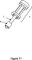
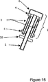
いくつかの利用で科学的改質装置を有する中央支持管はまた、図10、16〜18に示されるように、熱交換器または再燃焼装置を装着または備えることができる。その後、この熱交換器は、吸入燃料/空気混合物を予熱するために使用する、燃料電池スタック排出ガスからの熱を抽出する。再燃焼装置は、Pt/Al2O3粒子、PtRh/CeO2/AlO3ペレット、およびPt/α−Al2O3フォームモノリスなどの燃焼触媒を利用して、消費されていない燃料を熱し、変換することにより同様の効果を達成する。熱交換器/再燃焼装置および中央支持管(2)アセンブリを、図11に示されるように、整備または交換するために、スタックから取り外すことができる。 A central support tube with a scientific reformer in some applications can also be fitted or equipped with a heat exchanger or recombustion device, as shown in FIGS. The heat exchanger then extracts heat from the fuel cell stack exhaust gas that is used to preheat the intake fuel / air mixture. The recombustion device utilizes combustion catalysts such as Pt / Al 2 O 3 particles, PtRh / CeO 2 / AlO 3 pellets, and Pt / α-Al 2 O 3 foam monoliths to heat the unconsumed fuel, A similar effect is achieved by conversion. The heat exchanger / reburner and central support tube (2) assembly can be removed from the stack for maintenance or replacement, as shown in FIG.
燃料電池(3)の操作中、マニホルドの熱は、熱的に抑制した応力を作成する。図13に示されるように、半球体ドームの形に成形したマニホルド(15)の取り付けは、マニホルド内の応力集中を削減する。図14に示されるように、平面密封表面(16)を備えるマニホルド(6)は、密封表面(16)および円筒型囲壁(17)の交差で応力集中が認められる。交差での隅肉(18)は、熱誘発応力を削減する。半球形のマニホルド(16)は、マニホルドの重量を削減することにより、さらに熱誘発応力を削減する。一実施態様では、マニホルドの機能を、図18に示されるように、電流収集板(5)をガス不浸透性である絶縁部品に結合することにより、実行することができる。これは、別個のマニホルド部分を取り除き、システムの全費用を削減することができる。 During operation of the fuel cell (3), the manifold heat creates a thermally constrained stress. As shown in FIG. 13, the attachment of a manifold (15) shaped in the shape of a hemispherical dome reduces stress concentrations in the manifold. As shown in FIG. 14, the manifold (6) with the planar sealing surface (16) has a stress concentration at the intersection of the sealing surface (16) and the cylindrical enclosure (17). The fillet (18) at the intersection reduces heat-induced stress. The hemispherical manifold (16) further reduces heat-induced stress by reducing the weight of the manifold. In one embodiment, the function of the manifold can be performed by coupling the current collecting plate (5) to an insulating component that is gas impermeable, as shown in FIG. This can eliminate a separate manifold section and reduce the overall cost of the system.
以下の実施例は、本発明を示し、本発明の理解に役立つ説明を行うものであるが、その後に続く請求項で定義される発明の範囲を限定するものと解釈されるべきではない。 The following examples illustrate the invention and provide a useful explanation for understanding the invention, but should not be construed to limit the scope of the invention as defined in the claims that follow.
以下の実施例は、36の燃料電池を備える燃料電池システムの構造を説明する。電流収集板と、燃料電池板と、マニホルドのキャップは、アルミナまたはマコールで作られ、当業者に周知のようにゲル鋳造法に従い製造された。中央支持管を押出アルミナ管から構築し、1550℃まで炉で焼くことにより、検査した。濃密なサフィルファイバーボードを、絶縁板を構築するために使用し、サフィルフェルトをガスケット作成のために使用した。 The following examples illustrate the structure of a fuel cell system comprising 36 fuel cells. The current collector plate, fuel cell plate, and manifold cap were made of alumina or macor and manufactured according to a gel casting method as is well known to those skilled in the art. A central support tube was constructed from extruded alumina tube and examined by baking in an oven to 1550 ° C. Dense safil fiberboard was used to construct the insulation board and safil felt was used to make the gasket.
燃料電池板と、電流収集板と、マニホルドキャップと、絶縁板は、950℃まで事前に炉で焼き、これらの部品が確実に高温利用に適するようにした。熱電対、電流収集、または通気のための穴または溝など、追加の機能を部品に加えた。注入ピンは、事前に押出アルミナ管(外径2.6mm;内径1.4mm)を切断することにより作られた。注入ピンの長さは、5〜15mmの間で、燃料電池の長さにより異なる。その後、注入ピンを、アルミナ結合剤、Resbond 989高純度アルミナセラミックを使用して燃料電池板上に取り付け、固定し、その後2時間600℃で硬化させ、確実に適切な密閉が形成されるようにした。 The fuel cell plate, current collecting plate, manifold cap, and insulating plate were pre-baked in a furnace to 950 ° C. to ensure that these components were suitable for high temperature use. Additional features were added to the part, such as holes or grooves for thermocouples, current collection, or ventilation. The injection pin was made by cutting an extruded alumina tube (outer diameter 2.6 mm; inner diameter 1.4 mm) in advance. The length of the injection pin is between 5 and 15 mm, depending on the length of the fuel cell. The injection pin is then mounted and secured onto the fuel cell plate using an alumina binder, Resbond 989 high purity alumina ceramic, and then cured at 600 ° C. for 2 hours to ensure a proper seal is formed. did.
米国特許出願第S/N60/526,398号の表題、「サーメット電解質使用の陽極支持の固体酸化物型燃料電池」に公開された方法により、36のチューブ状の燃料電池を準備した。その後、燃料電池を電流収集板に取り付けた。電気的接続を望ましい出力電圧に達成した。例えば、36V出力には直列に配線された36の燃料電池が必要で、18V出力には、18組の直列に配列36の燃料が必要である。電池間の電気的接続は、銀およびNi/YSZサーメットなどの導体金属板/発泡体および/または導体ペーストの合体を使用した。その後、このアセンブリは、70℃で2時間乾燥させた。アルミナ結合剤の層を、その後、電流収集板上に添付し、電流収集板および燃料電池の間の接続に密閉した。 Thirty-six tubular fuel cells were prepared by the method published in the title of US patent application S / N 60 / 526,398, “Anode-Supported Solid Oxide Fuel Cell Using Cermet Electrolyte”. Thereafter, the fuel cell was attached to the current collecting plate. Electrical connection was achieved to the desired output voltage. For example, 36V output requires 36 fuel cells wired in series, and 18V output requires 18 sets of fuel in array 36 in series. The electrical connection between the cells used a combination of conductive metal plates / foam and / or conductive paste such as silver and Ni / YSZ cermet. The assembly was then dried at 70 ° C. for 2 hours. A layer of alumina binder was then affixed onto the current collection plate and sealed to the connection between the current collection plate and the fuel cell.
リフォーミング触媒を中央支持管に加えた。触媒の4つの部分を連続添加し、リフォーミング/燃焼反応が発熱から吸熱に移るように(部分1〜4)、POX触媒が初めに確実に適合するようにした。触媒部分を、アルミナ結合剤(Resbond 989高純度アルミナセラミック)を備える位置に固定した。その後、中央支持管を4〜6時間、70℃で保存処理した。 Reforming catalyst was added to the central support tube. Four parts of the catalyst were added in succession to ensure that the POX catalyst was initially fitted so that the reforming / combustion reaction went from exothermic to endothermic (parts 1-4). The catalyst portion was fixed in position with an alumina binder (Resbond 989 high purity alumina ceramic). The central support tube was then stored at 70 ° C. for 4-6 hours.
完了した中央支持管および燃料電池板をResbond 989高純度アルミナセラミックを使用して、結合した。その後、このアセンブリを2時間、70℃で保存処理した。2つのサフィルフェルトを、注入ピン上に設置した。燃料電池および電流収集板を含むアセンブリと、中央支持管および燃料電池板を含むアセンブリを、図3に示すように、共に組み立てた。 The completed central support tube and fuel cell plate were bonded using Resbond 989 high purity alumina ceramic. The assembly was then stored at 70 ° C. for 2 hours. Two safil felts were placed on the injection pin. The assembly including the fuel cell and current collecting plate and the assembly including the central support tube and the fuel cell plate were assembled together as shown in FIG.
マニホルドは燃料電池板に装着され、絶縁板は電流収集板上に位置付けられた。再燃焼装置触媒は、中央支持管周辺の絶縁板の10mm上に、に設置された。そして、再燃焼装置触媒のOD、またサフィルフェルトが電流収集板のODと同等になるまで、サフィルフェルトが再燃焼装置周辺に巻かれた。サフィルフェルトをアセンブリ、または「スタック」は、熱電対と、陽陰線のための絶縁管を含み、その後、4時間、70℃で保存処理した。 The manifold was mounted on the fuel cell plate and the insulating plate was positioned on the current collecting plate. The reburner catalyst was installed 10 mm above the insulating plate around the central support tube. Then, the sapphire felt was wound around the recombustion device until the OD of the recombustion device catalyst and the safel felt were equal to the OD of the current collecting plate. The safil felt assembly, or “stack”, included a thermocouple and an insulating tube for the positive and negative lines, and then stored at 70 ° C. for 4 hours.
その後、スタックを、燃料電池板および電流収集板の外径よりもわずかに大きい内径を有するチューブ状熱交換器にはめた。熱交換器を熱交換器の内壁の穴が燃料電池の活性電極から一列になるように位置付けた。その後、このアセンブリを適切な絶縁本体に適応し、システム操作中、燃料電池システムの外部接合部分の温度が80℃以下に保持するように、構築した。 The stack was then fitted into a tubular heat exchanger having an inner diameter slightly larger than the outer diameter of the fuel cell plate and current collecting plate. The heat exchanger was positioned so that the holes in the inner wall of the heat exchanger were aligned with the active electrode of the fuel cell. The assembly was then adapted to a suitable insulating body and constructed so that the temperature of the external junction of the fuel cell system was kept below 80 ° C. during system operation.
燃料電池システムを以下の状況下で検査した。システムを流速1〜2.5L/分で、酸素/プロパン燃料(各、2.4:1)で始めた。再燃焼装置の裏にある、電子点火装置を使用して、燃焼を達成した。システムは、10分弱で700℃に到達した。この時点で、酸素/プロパンの比率は、システムの望ましい負荷(満載=1.8;低負荷=2.2)により、1.8および2.2の間で変化する。比率は、高負荷需要中、水素製品を最大限にし、スタックの操作温度の平衡を保つことにより変化し、満載下で、850℃まで増加する。1.9の酸素/プロパンの比率を備えて操作する場合、システムは、835℃で57Wを生産した。その後、システムを削減した流速(全開流量の1/4)で中断し、2.2の酸素/プロパンの比率を維持した。 The fuel cell system was tested under the following conditions. The system was started with oxygen / propane fuel (2.4: 1 each) at a flow rate of 1-2.5 L / min. Combustion was achieved using an electronic igniter behind the reburner. The system reached 700 ° C. in less than 10 minutes. At this point, the oxygen / propane ratio varies between 1.8 and 2.2 depending on the desired load of the system (full load = 1.8; low load = 2.2). The ratio changes by maximizing the hydrogen product and keeping the stack operating temperature in balance during high load demand and increases to 850 ° C. under full load. When operating with an oxygen / propane ratio of 1.9, the system produced 57 W at 835 ° C. The system was then interrupted with a reduced flow rate (1/4 of the full flow rate) to maintain an oxygen / propane ratio of 2.2.
前述の発明は明瞭さと理解を目的にいくらか詳細を説明したが、本開示を読むことにより、添付の特許請求の範囲における本発明の正確な範囲から逸脱することなく、形式および詳細に様々な変更が可能であることが、当業者には理解されるであろう。 Although the foregoing invention has been described in some detail for purposes of clarity and understanding, various changes in form and detail may be made by reading this disclosure without departing from the exact scope of the invention as set forth in the appended claims. Those skilled in the art will appreciate that this is possible.
Claims (13)
複数の燃料電池;
燃料電池板であって、該燃料電池板が、複数の注入ピンを備え、かつ、各燃料電池の第一の末端が、それぞれの注入ピン上に設置されるか;あるいは、該燃料電池板が、複数の空洞を備え、かつ、各燃料電池の第一の末端が、それぞれの空洞内に挿入される、燃料電池板;
電流収集板であって、各燃料電池の第二の末端が、該電流収集板にしっかりと取り付けられ、該複数の燃料電池および該電流収集板が、一緒になって、単一の取り外し可能なアセンブリを形成する、電流収集板;
該電流収集板と接触する電流収集システムであって、該電流収集システムは、該複数の燃料電池と電気的に接続されている、電流収集システム;および
中央支持管であって、該中央支持管の第一の末端が、該燃料電池板に結合され、該電流収集板は、該中央支持管に滑りによりかみ合わされる、中央支持管
を備え、該複数の燃料電池および該電流収集板は、該固体酸化物型燃料電池システムの操作中、該複数の燃料電池の長手方向軸に対して平行方向に移動可能である、
固体酸化物型燃料電池システム。A solid oxide fuel cell system,
Multiple fuel cells;
A fuel cell plate, wherein the fuel cell plate comprises a plurality of injection pins and the first end of each fuel cell is located on the respective injection pin; or A fuel cell plate comprising a plurality of cavities and a first end of each fuel cell is inserted into the respective cavity ;
A current collection plate, wherein the second end of each fuel cell is securely attached to the current collection plate, and the plurality of fuel cells and the current collection plate are combined together into a single removable A current collecting plate forming an assembly ;
A current collection system in contact with the current collection plate, wherein the current collection system is electrically connected to the plurality of fuel cells; and a central support tube, the central support tube A first support end coupled to the fuel cell plate, the current collection plate comprising a central support tube that is slidably engaged with the central support tube, the plurality of fuel cells and the current collection plate comprising: Movable in a direction parallel to the longitudinal axis of the plurality of fuel cells during operation of the solid oxide fuel cell system;
Solid oxide fuel cell system.
Applications Claiming Priority (3)
| Application Number | Priority Date | Filing Date | Title |
|---|---|---|---|
| US10/939,185 | 2004-09-09 | ||
| US10/939,185 US7629069B2 (en) | 2004-09-09 | 2004-09-09 | Solid oxide fuel cell system |
| PCT/US2005/032299 WO2006029372A2 (en) | 2004-09-09 | 2005-09-08 | Solid oxide fuel cell system |
Publications (3)
| Publication Number | Publication Date |
|---|---|
| JP2008512846A JP2008512846A (en) | 2008-04-24 |
| JP2008512846A5 JP2008512846A5 (en) | 2008-10-16 |
| JP5161572B2 true JP5161572B2 (en) | 2013-03-13 |
Family
ID=35996630
Family Applications (1)
| Application Number | Title | Priority Date | Filing Date |
|---|---|---|---|
| JP2007531404A Active JP5161572B2 (en) | 2004-09-09 | 2005-09-08 | Solid oxide fuel cell system |
Country Status (11)
| Country | Link |
|---|---|
| US (2) | US7629069B2 (en) |
| EP (1) | EP1825546B1 (en) |
| JP (1) | JP5161572B2 (en) |
| KR (1) | KR20070100688A (en) |
| CN (1) | CN101053105A (en) |
| AT (1) | ATE521999T1 (en) |
| AU (1) | AU2005282313B2 (en) |
| CA (1) | CA2579649C (en) |
| RU (1) | RU2357331C2 (en) |
| UA (1) | UA88920C2 (en) |
| WO (1) | WO2006029372A2 (en) |
Families Citing this family (32)
| Publication number | Priority date | Publication date | Assignee | Title |
|---|---|---|---|---|
| US7629069B2 (en) * | 2004-09-09 | 2009-12-08 | Nanodynamics Energy, Inc. | Solid oxide fuel cell system |
| KR101300541B1 (en) | 2005-06-24 | 2013-09-02 | 프레스톤 프로닥츠 코포레이션 | Method for inhibiting corrosion in brazed metal surfaces and coolants and additives for use therein |
| JP4943037B2 (en) * | 2005-07-27 | 2012-05-30 | 京セラ株式会社 | Fuel cell module |
| JP4910347B2 (en) * | 2005-09-27 | 2012-04-04 | トヨタ自動車株式会社 | Fuel cell module with current collecting electrode that also serves as a spacer |
| JP2007172846A (en) * | 2005-12-19 | 2007-07-05 | National Institute Of Advanced Industrial & Technology | Tube type electrochemical reactor cell and electrochemical reaction system composed by it |
| JP4240530B2 (en) * | 2006-09-15 | 2009-03-18 | Toto株式会社 | Fuel cell body, fuel cell unit, fuel cell stack, and fuel cell including them |
| CN101821884B (en) * | 2007-08-03 | 2013-10-23 | 纳诺Cp有限责任公司 | Solid oxide fuel cell systems with improved gas channeling and heat exchange |
| US8309270B2 (en) * | 2007-08-03 | 2012-11-13 | Cp Sofc Ip, Llc | Solid oxide fuel cell systems with improved gas channeling and heat exchange |
| US20090050680A1 (en) * | 2007-08-24 | 2009-02-26 | Protonex Technology Corporation | Method for connecting tubular solid oxide fuel cells and interconnects for same |
| US8409760B2 (en) * | 2009-01-20 | 2013-04-02 | Adaptive Materials, Inc. | Method for controlling a water based fuel reformer |
| US8936888B2 (en) * | 2009-01-30 | 2015-01-20 | Adaptive Materials, Inc. | Fuel cell system with flame protection member |
| DE102009037148B4 (en) * | 2009-08-06 | 2014-02-20 | Fraunhofer-Gesellschaft zur Förderung der angewandten Forschung e.V. | Solid oxide fuel cell system |
| KR101040815B1 (en) | 2009-11-17 | 2011-06-13 | 삼성에스디아이 주식회사 | Manifold Device for Tube Type Solid Oxide Fuel Cell |
| US20110189587A1 (en) * | 2010-02-01 | 2011-08-04 | Adaptive Materials, Inc. | Interconnect Member for Fuel Cell |
| US20110189578A1 (en) * | 2010-02-01 | 2011-08-04 | Adaptive Materials, Inc. | Fuel cell system including a resilient manifold interconnecting member |
| JP5383550B2 (en) * | 2010-02-24 | 2014-01-08 | 京セラ株式会社 | Fuel cell module |
| US8796888B2 (en) | 2010-07-07 | 2014-08-05 | Adaptive Materials, Inc. | Wearable power management system |
| KR101186537B1 (en) | 2011-05-17 | 2012-10-08 | 한국에너지기술연구원 | Micro cylindrical solid oxide fuel cell stack and solid oxide fuel cell power generation system comprising the same |
| TWI427308B (en) * | 2011-10-18 | 2014-02-21 | Iner Aec Executive Yuan | Testing device for solid oxide fuel cell |
| KR101334930B1 (en) * | 2011-12-08 | 2013-11-29 | 한국에너지기술연구원 | An equipment for a solid oxide fuel cell or solid oxide electrolysis cell |
| JP5975255B2 (en) * | 2012-02-21 | 2016-08-23 | Toto株式会社 | Fuel cell device |
| US10109867B2 (en) | 2013-06-26 | 2018-10-23 | Upstart Power, Inc. | Solid oxide fuel cell with flexible fuel rod support structure |
| AU2014408260B2 (en) | 2014-10-07 | 2020-12-17 | Upstart Power Inc | SCOFC-conduction |
| DE102015210136A1 (en) * | 2015-06-02 | 2016-12-08 | Robert Bosch Gmbh | fuel cell device |
| US20170092964A1 (en) * | 2015-09-28 | 2017-03-30 | General Electric Company | Fuel cell module including heat exchanger and method of operating such module |
| US10790523B2 (en) | 2015-10-20 | 2020-09-29 | Upstart Power, Inc. | CPOX reactor control system and method |
| EP3365934B1 (en) | 2015-10-20 | 2022-12-21 | Upstart Power, Inc. | Improved cpox fuel reformer |
| EP3216443A1 (en) | 2016-03-10 | 2017-09-13 | Athenion AG | Beverage preparation capsule for delivery of a solubilisate |
| EP3497741A4 (en) | 2016-08-11 | 2020-04-01 | Upstart Power, Inc. | Planar solid oxide fuel unit cell and stack |
| JP7001407B2 (en) * | 2016-12-02 | 2022-02-03 | 森村Sofcテクノロジー株式会社 | Fuel cell cell stack device |
| CN109361005A (en) * | 2018-11-02 | 2019-02-19 | 浙江晨阳新材料有限公司 | A kind of solid oxide fuel cell device |
| CN111969165B (en) * | 2020-08-17 | 2022-07-29 | 北京理工大学 | Tubular solid oxide fuel cell current-collecting connection structure |
Family Cites Families (35)
| Publication number | Priority date | Publication date | Assignee | Title |
|---|---|---|---|---|
| US3457052A (en) * | 1965-09-14 | 1969-07-22 | Westinghouse Electric Corp | High temperature,electrically conductive hermetic seals |
| US3718506A (en) * | 1971-02-22 | 1973-02-27 | Bbc Brown Boveri & Cie | Fuel cell system for reacting hydrocarbons |
| US4374185A (en) * | 1981-05-14 | 1983-02-15 | United Technologies Corporation | High temperature, high pressure chemical resistant seal material |
| US4374184A (en) * | 1981-09-29 | 1983-02-15 | Westinghouse Electric Corp. | Fuel cell generator and method of operating same |
| US4640875A (en) | 1985-02-07 | 1987-02-03 | Westinghouse Electric Corp. | Fuel cell generator containing a gas sealing means |
| US4728584A (en) | 1986-10-21 | 1988-03-01 | Westinghouse Electric Corp. | Fuel cell generator containing self-supporting high gas flow solid oxide electrolyte fuel cells |
| DE3640209A1 (en) | 1986-11-25 | 1988-06-01 | Basf Ag | METHANOL / AIR FUEL CELL BATTERIES WITH POLYMERIC ELECTROLYTE HIGH ENERGY AND PERFORMANCE DENSITY AND TUBULAR ARRANGEMENT |
| US4808491A (en) | 1988-02-16 | 1989-02-28 | Westinghouse Electric Corp. | Corner heating in rectangular solid oxide electrochemical cell generators |
| DE68908140T2 (en) | 1988-12-22 | 1994-02-03 | Ngk Insulators Ltd | Ceramic tube with a tubular jacket closed on one side and process for its production. |
| JP2601911B2 (en) * | 1989-06-30 | 1997-04-23 | 三菱重工業株式会社 | Cylindrical solid oxide fuel cell |
| US5273839A (en) | 1989-07-28 | 1993-12-28 | Ngk Insulators, Ltd. | Fuel cell generator |
| US5045169A (en) * | 1990-02-05 | 1991-09-03 | Westinghouse Electric Corp. | Solid oxide electrolyte electrochemical oxygen generator |
| JP3277512B2 (en) | 1991-01-21 | 2002-04-22 | 東陶機器株式会社 | Power generator incorporating a fuel cell |
| US5273837A (en) | 1992-12-23 | 1993-12-28 | Corning Incorporated | Solid electrolyte fuel cells |
| DE69614632T2 (en) * | 1995-04-12 | 2002-02-07 | Int Fuel Cells Corp | FUEL PROCESS APPARATUS WITH OVEN FOR FUEL CELL POWER PLANT |
| JP3263561B2 (en) * | 1995-04-14 | 2002-03-04 | 三菱重工業株式会社 | Solid electrolyte fuel cell |
| US5733675A (en) * | 1995-08-23 | 1998-03-31 | Westinghouse Electric Corporation | Electrochemical fuel cell generator having an internal and leak tight hydrocarbon fuel reformer |
| RU2129323C1 (en) | 1996-08-08 | 1999-04-20 | Российский федеральный ядерный центр - Всероссийский научно- исследовательский институт технической физики | Battery of solid-oxide fuel cells |
| BR9812715A (en) | 1997-10-01 | 2000-08-22 | Waikatolink Ltd | Integrated solid oxide fuel cell and reformer |
| JPH11111314A (en) * | 1997-10-03 | 1999-04-23 | Kansai Electric Power Co Inc:The | Cathode collecting structure for solid electrolyte fuel cell, and solid electrolyte fuel cell power generating module using the same |
| US6379485B1 (en) | 1998-04-09 | 2002-04-30 | Siemens Westinghouse Power Corporation | Method of making closed end ceramic fuel cell tubes |
| US6428920B1 (en) * | 2000-05-18 | 2002-08-06 | Corning Incorporated | Roughened electrolyte interface layer for solid oxide fuel cells |
| WO2001089010A1 (en) | 2000-05-18 | 2001-11-22 | Corning Incorporated | Solid oxide fuel cells with symmetric composite electrodes |
| JP5234554B2 (en) * | 2001-03-22 | 2013-07-10 | 独立行政法人産業技術総合研究所 | Solid oxide fuel cell stack structure |
| JP2002313374A (en) * | 2001-04-09 | 2002-10-25 | Mitsubishi Heavy Ind Ltd | Fuel cell system |
| DE10132078A1 (en) * | 2001-07-05 | 2003-01-23 | Stephan Blum | electrode assembly |
| US20050031923A1 (en) | 2001-09-06 | 2005-02-10 | Masahiro Kuroishi | Solid state electrolytic fuel cell |
| US20030054215A1 (en) | 2001-09-20 | 2003-03-20 | Honeywell International, Inc. | Compact integrated solid oxide fuel cell system |
| CA2466262A1 (en) | 2001-11-06 | 2003-05-15 | Freedom Cell Power Corporation | Fuel cell element |
| WO2003096470A1 (en) | 2002-05-07 | 2003-11-20 | The Regents Of The University Of California | Electrochemical cell stack assembly |
| US7229712B2 (en) * | 2003-03-07 | 2007-06-12 | Microcell Corporation | Fuel cell structures and assemblies |
| JP2004356014A (en) | 2003-05-30 | 2004-12-16 | Sanyo Electric Co Ltd | Solid oxide fuel cell, solid oxide fuel cell assembly, solid oxide fuel cell module, and solid oxide fuel cell generator |
| US7767329B2 (en) * | 2003-11-17 | 2010-08-03 | Adaptive Materials, Inc. | Solid oxide fuel cell with improved current collection |
| US20050282060A1 (en) * | 2004-06-18 | 2005-12-22 | Mti Micro Fuel Cells, Inc. | Fuel cell endplate system |
| US7629069B2 (en) * | 2004-09-09 | 2009-12-08 | Nanodynamics Energy, Inc. | Solid oxide fuel cell system |
-
2004
- 2004-09-09 US US10/939,185 patent/US7629069B2/en active Active
-
2005
- 2005-09-08 RU RU2007114025/09A patent/RU2357331C2/en not_active IP Right Cessation
- 2005-09-08 AT AT05796661T patent/ATE521999T1/en not_active IP Right Cessation
- 2005-09-08 WO PCT/US2005/032299 patent/WO2006029372A2/en active Application Filing
- 2005-09-08 AU AU2005282313A patent/AU2005282313B2/en active Active
- 2005-09-08 CA CA2579649A patent/CA2579649C/en active Active
- 2005-09-08 CN CNA2005800379229A patent/CN101053105A/en active Pending
- 2005-09-08 EP EP05796661A patent/EP1825546B1/en active Active
- 2005-09-08 KR KR1020077007946A patent/KR20070100688A/en not_active Application Discontinuation
- 2005-09-08 UA UAA200703879A patent/UA88920C2/en unknown
- 2005-09-08 JP JP2007531404A patent/JP5161572B2/en active Active
-
2009
- 2009-11-17 US US12/620,046 patent/US7875403B2/en active Active
Also Published As
| Publication number | Publication date |
|---|---|
| RU2007114025A (en) | 2008-10-27 |
| WO2006029372A2 (en) | 2006-03-16 |
| AU2005282313A1 (en) | 2006-03-16 |
| RU2357331C2 (en) | 2009-05-27 |
| ATE521999T1 (en) | 2011-09-15 |
| CA2579649A1 (en) | 2006-03-16 |
| EP1825546A2 (en) | 2007-08-29 |
| US7629069B2 (en) | 2009-12-08 |
| UA88920C2 (en) | 2009-12-10 |
| AU2005282313B2 (en) | 2010-08-12 |
| WO2006029372A3 (en) | 2007-01-25 |
| US20100068582A1 (en) | 2010-03-18 |
| JP2008512846A (en) | 2008-04-24 |
| CN101053105A (en) | 2007-10-10 |
| US7875403B2 (en) | 2011-01-25 |
| EP1825546B1 (en) | 2011-08-24 |
| EP1825546A4 (en) | 2009-09-16 |
| US20060051642A1 (en) | 2006-03-09 |
| CA2579649C (en) | 2013-05-07 |
| KR20070100688A (en) | 2007-10-11 |
Similar Documents
| Publication | Publication Date | Title |
|---|---|---|
| JP5161572B2 (en) | Solid oxide fuel cell system | |
| JP4794178B2 (en) | Solid electrolyte fuel cell | |
| US20100086824A1 (en) | Assemblies of hollow electrode electrochemical devices | |
| JP5119234B2 (en) | Fuel cell module | |
| EP2296212B1 (en) | A Cell Module for a Solid Oxide Fuel Cell | |
| KR20170065610A (en) | Sofc-conduction | |
| JP2005518645A (en) | Fuel cell stacking and sealing | |
| JP4956946B2 (en) | Fuel cell | |
| JP2006066387A (en) | Fuel cell battery | |
| JP5122319B2 (en) | Solid oxide fuel cell | |
| JP4537292B2 (en) | Cylindrical fuel cell | |
| US20110008712A1 (en) | Fuel Cell Having Single Body Support | |
| JP4513281B2 (en) | Fuel cell | |
| JP2007128739A (en) | Fuel cell | |
| JP2004247232A (en) | High-temperature solid oxide fuel cell | |
| JP2008147026A (en) | Solid oxide fuel cell | |
| JP5139850B2 (en) | Solid oxide fuel cell | |
| JP4475861B2 (en) | Solid oxide fuel cell unit | |
| JP6973759B1 (en) | Tube type SOFC | |
| JP6982586B2 (en) | Fuel cell cartridges, fuel cell modules and combined cycle systems | |
| WO2021140852A1 (en) | Fuel cell power generating system | |
| JP6466136B2 (en) | Fuel cell module | |
| JP2004335162A (en) | Operation method of solid oxide type fuel cell |
Legal Events
| Date | Code | Title | Description |
|---|---|---|---|
| A521 | Request for written amendment filed |
Free format text: JAPANESE INTERMEDIATE CODE: A523 Effective date: 20080901 |
|
| A621 | Written request for application examination |
Free format text: JAPANESE INTERMEDIATE CODE: A621 Effective date: 20080901 |
|
| A977 | Report on retrieval |
Free format text: JAPANESE INTERMEDIATE CODE: A971007 Effective date: 20111102 |
|
| A131 | Notification of reasons for refusal |
Free format text: JAPANESE INTERMEDIATE CODE: A131 Effective date: 20111129 |
|
| A601 | Written request for extension of time |
Free format text: JAPANESE INTERMEDIATE CODE: A601 Effective date: 20120222 |
|
| A602 | Written permission of extension of time |
Free format text: JAPANESE INTERMEDIATE CODE: A602 Effective date: 20120229 |
|
| A521 | Request for written amendment filed |
Free format text: JAPANESE INTERMEDIATE CODE: A523 Effective date: 20120329 |
|
| TRDD | Decision of grant or rejection written | ||
| A01 | Written decision to grant a patent or to grant a registration (utility model) |
Free format text: JAPANESE INTERMEDIATE CODE: A01 Effective date: 20121122 |
|
| A61 | First payment of annual fees (during grant procedure) |
Free format text: JAPANESE INTERMEDIATE CODE: A61 Effective date: 20121214 |
|
| R150 | Certificate of patent or registration of utility model |
Ref document number: 5161572 Country of ref document: JP Free format text: JAPANESE INTERMEDIATE CODE: R150 Free format text: JAPANESE INTERMEDIATE CODE: R150 |
|
| FPAY | Renewal fee payment (event date is renewal date of database) |
Free format text: PAYMENT UNTIL: 20151221 Year of fee payment: 3 |
|
| R250 | Receipt of annual fees |
Free format text: JAPANESE INTERMEDIATE CODE: R250 |
|
| R250 | Receipt of annual fees |
Free format text: JAPANESE INTERMEDIATE CODE: R250 |
|
| R250 | Receipt of annual fees |
Free format text: JAPANESE INTERMEDIATE CODE: R250 |
|
| R250 | Receipt of annual fees |
Free format text: JAPANESE INTERMEDIATE CODE: R250 |
|
| R250 | Receipt of annual fees |
Free format text: JAPANESE INTERMEDIATE CODE: R250 |
|
| R250 | Receipt of annual fees |
Free format text: JAPANESE INTERMEDIATE CODE: R250 |
|
| R250 | Receipt of annual fees |
Free format text: JAPANESE INTERMEDIATE CODE: R250 |
|
| R250 | Receipt of annual fees |
Free format text: JAPANESE INTERMEDIATE CODE: R250 |
|
| R250 | Receipt of annual fees |
Free format text: JAPANESE INTERMEDIATE CODE: R250 |