JP5157877B2 - Imaging element mounting structure and imaging apparatus - Google Patents
Imaging element mounting structure and imaging apparatus Download PDFInfo
- Publication number
- JP5157877B2 JP5157877B2 JP2008322108A JP2008322108A JP5157877B2 JP 5157877 B2 JP5157877 B2 JP 5157877B2 JP 2008322108 A JP2008322108 A JP 2008322108A JP 2008322108 A JP2008322108 A JP 2008322108A JP 5157877 B2 JP5157877 B2 JP 5157877B2
- Authority
- JP
- Japan
- Prior art keywords
- image sensor
- lens barrel
- frame
- bent
- image pickup
- Prior art date
- Legal status (The legal status is an assumption and is not a legal conclusion. Google has not performed a legal analysis and makes no representation as to the accuracy of the status listed.)
- Expired - Fee Related
Links
Images


Landscapes
- Studio Devices (AREA)
Description
本発明は、撮像素子の取付構造及び撮像装置に関する。 The present invention relates to an imaging element mounting structure and an imaging apparatus.
デジタルカメラ、特に、ズームレンズを備えたコンパクトタイプのデジタルカメラでは、カメラの薄型を図るため、プリズムを用いた屈曲光学系が用いられている(例えば、特許文献1参照)。このような屈曲光学系は、デジタルカメラの前面から取り込んだ被写体光をプリズムによって反射させて、撮像素子に導くものである。このような屈曲光学系においては、プリズムよりも被写体側に配置されたレンズ群の光軸は、プリズムよりも撮像素子側に配置されたレンズ群の光軸に対して直交している。また、プリズムよりも被写体側のレンズ群の光軸がデジタルカメラの前面に対して垂直であり、プリズムよりも撮像素子側のレンズ群の光軸がデジタルカメラの前面に対して平行である。そして、プリズムよりも被写体側のレンズ群のレンズ枚数がプリズムよりも撮像素子側のレンズ群のレンズ枚数よりも少なくなっているから、デジタルカメラの前後長を短くすることができる。つまり、デジタルカメラの薄型を図ることができる。
ところで、デジタルカメラにおいては、CCD型やCMOS型の撮像素子が用いられている。撮像素子をデジタルカメラに内蔵する際には、図8に示すように、撮像素子120が実装された回路基板121と中央部に開口が形成された枠状の金属板122とを、この回路基板121上に実装された撮像素子120の受光面が枠状の金属板122の開口部に嵌るように位置合わせし、この状態で金属板122を回路基板121の上に接合してユニット化し、このユニットを鏡胴に組み付けるようになっている。
Incidentally, in a digital camera, a CCD type or CMOS type image sensor is used. When the image pickup device is built in the digital camera, as shown in FIG. 8, a
図8に示されたユニットを薄型に構成された屈曲光学系の鏡胴に取り付けると、図9に示すようになる。ここで、図9は鏡胴104を示した側面図であり、鏡胴104の上端部104a内にプリズムが取り付けられ、鏡胴104の上端前部104bから取り込まれた被写体光がプリズムによって反射されて、鏡胴104内を通って鏡胴104の下端部104cまで導かれる。
When the unit shown in FIG. 8 is attached to a lens barrel of a thin bending optical system, it is as shown in FIG. Here, FIG. 9 is a side view showing the
撮像素子120が鏡胴104の下端部104cの開口に向き合った状態で、金属板122が鏡胴104の下端部104cに接合されている。金属板122の前後長は鏡胴104の前後長よりも大きく、金属板122の前側の部分が鏡胴104の前面104dよりも前にはみ出ており、金属板122の後ろ側の部分が鏡胴104の後面104eよりも後ろにはみ出ている。
The
そのため、デジタルカメラの前後長、つまり厚さを金属板122の前後長よりも小さいものとすることができず、デジタルカメラが厚くなってしまう。
Therefore, the front and rear length of the digital camera, that is, the thickness cannot be made smaller than the front and rear length of the
そこで、本発明が解決しようとする課題は、撮像素子を囲む枠状板が鏡胴からはみ出る長さを短くできるようにすることである。 Therefore, the problem to be solved by the present invention is to make it possible to shorten the length of the frame-shaped plate surrounding the image sensor protruding from the lens barrel.
以上の課題を解決するために、請求項1に係る発明は、撮像素子が基板の上に実装され、枠状板が、その開口に位置する前記撮像素子を囲繞し、前記枠状板の開口を挟んで相対する2辺部分が他の部分に対して折り曲げられ、前記他の部分が前記基板の上に接合され、前記撮像素子が鏡胴の開口に向き合った状態で前記枠状板が前記鏡胴に取り付けられていることを特徴とする。
請求項2に係る発明は、前記枠状板のうち前記撮像素子を挟んで相対する2辺部分が他の部分に対して該撮像素子方向に折り曲げられていることを特徴とする。
請求項3に係る発明は、前記枠状板のうち前記撮像素子を挟んで相対する2辺部分の一方が他の部分に対して該撮像素子方向に、他方が該撮像素子とは逆方向に折り曲げられていることを特徴とする。
請求項4に係る発明は、前記枠状板のうち前記撮像素子を挟んで相対する2辺部分が他の部分に対して該撮像素子とは逆方向に折り曲げられていることを特徴とする。
In order to solve the above problems, the invention according to claim 1 is directed to an image pickup device mounted on a substrate, a frame-shaped plate surrounding the image pickup device positioned in the opening, and an opening of the frame-shaped plate. The two opposite side portions are bent with respect to the other portion, the other portion is bonded onto the substrate, and the frame-like plate is in the state where the imaging element faces the opening of the lens barrel. It is attached to the lens barrel.
The invention according to
According to a third aspect of the present invention, in the frame-shaped plate, one of the two sides facing each other across the image sensor is in the direction of the image sensor relative to the other part, and the other is in the direction opposite to the image sensor. It is bent.
The invention according to claim 4 is characterized in that two side portions opposed to each other with the image pickup element sandwiched in the frame-shaped plate are bent in the opposite direction to the image pickup element with respect to the other parts.
請求項5に係る発明は、筐体と、前記筐体内に収容された鏡胴と、前記筐体内に収容された基板と、前記鏡胴の開口に向き合い、前記基板の上に実装された撮像素子と、前記鏡胴に取り付けられた枠状板であって、その開口に位置する前記撮像素子を囲繞する枠状板と、
前記鏡胴内に取り付けられ、前記筐体の前面側から取り込んだ像を前記鏡胴の開口を通じて前記撮像素子に結像する光学系と、を備え、前記枠状板の開口を挟んで相対する前片部及び後片部が他の部分に対して折り曲げられ、前記他の部分が前記基板の上に接合されていることを特徴とする。
請求項6に係る発明は、前記枠状板のうち前記撮像素子を挟んで相対する前片部及び後片部が他の部分に対して該撮像素子方向に折り曲げられ、前記他の部分が前記基板の上に接合されていることを特徴とする。
請求項7に係る発明は、記枠状板のうち前記撮像素子を挟んで相対する前片部及び後片部の一方が他の部分に対して該撮像素子方向に折り曲げられ、他方が該撮像素子とは逆方向に折り曲げられ前記他の部分が前記基板の上に接合されていることを特徴とする。
請求項8に係る発明は、前記枠状板のうち前記撮像素子を挟んで相対する前片部及び後片部が他の部分に対して該撮像素子とは逆方向に折り曲げられ、前記他の部分が前記基板の上に接合されていることを特徴とする。
According to a fifth aspect of the present invention, there is provided a housing, a lens barrel housed in the housing, a substrate housed in the housing, and an imaging mounted on the substrate facing the opening of the lens barrel. and the element, a front Symbol mirror frame-shaped plate mounted to the body, a frame-shaped plate surrounding the imaging element located in the opening,
An optical system that is mounted in the lens barrel and forms an image captured from the front side of the housing on the imaging element through the opening of the lens barrel, and is opposed to each other with the opening of the frame-shaped plate interposed therebetween The front piece portion and the rear piece portion are bent with respect to another portion, and the other portion is bonded onto the substrate.
In the invention according to
In the invention according to
In the invention according to
本発明によれば、枠状板のうち撮像素子を挟んで相対する部分が他の部分に対して折り曲げられているから、その部分が鏡胴からはみ出る長さを短くすることができる。そのため、撮像装置(デジタルカメラ)の薄型化を図ることができる。 According to the present invention, the part of the frame-like plate that faces the image sensor is bent with respect to the other part, so that the length of the part protruding from the lens barrel can be shortened. Therefore, it is possible to reduce the thickness of the imaging device (digital camera).
以下に、本発明を実施するための好ましい形態について図面を用いて説明する。但し、以下に述べる実施形態には、本発明を実施するために技術的に好ましい種々の限定が付されているが、発明の範囲を以下の実施形態及び図示例に限定するものではない。 Hereinafter, preferred embodiments for carrying out the present invention will be described with reference to the drawings. However, although various technically preferable limitations for implementing the present invention are given to the embodiments described below, the scope of the invention is not limited to the following embodiments and illustrated examples.
<第1の実施の形態>
図1は、本発明を適用した撮像装置の一実施形態としてのデジタルカメラ1を示した斜視図であり、図2は、デジタルカメラ1に内蔵された鏡胴4等を示した斜視図であり、図3は、鏡胴4等を示した斜視断面図である。図1では、デジタルカメラ1の内部構造を透視した状態で示されている。
<First Embodiment>
FIG. 1 is a perspective view showing a digital camera 1 as an embodiment of an imaging apparatus to which the present invention is applied, and FIG. 2 is a perspective view showing a lens barrel 4 and the like built in the digital camera 1. FIG. 3 is a perspective sectional view showing the lens barrel 4 and the like. In FIG. 1, the internal structure of the digital camera 1 is shown through.
このデジタルカメラ1においては、筐体2の上面にシャッターボタン3が設けられ、筐体2の内部に鏡胴4、撮像素子20及び回路基板21等が収容され、鏡胴4に屈曲光学系10及び撮像素子20が取り付けられている。なお、図示していないが、筐体2の背面側には、液晶ディスプレイパネル等で構成されるモニタや、モードスイッチやズームスイッチ等の各種スイッチが設けられている。
In this digital camera 1, a
鏡胴4は、筐体2の前面2aの上部から筐体2の内側を通って筐体2の下側にかけて配置されている。この鏡胴4は、鏡胴本体部5、対物レンズホルダ6、プリズムホルダ7及び可動レンズホルダ8等を有する。鏡胴本体部5は、屈曲光学系10による光路の前後左右を囲むように上下方向に延在している。鏡胴本体部5の下端が開口している。鏡胴本体部5の上端部にプリズムホルダ7が設けられ、プリズムホルダ7の前部に対物レンズホルダ6が設けられている。対物レンズホルダ6の開口部6aが筐体2の前面側で開口している。鏡胴本体部5の内部には、複数のレンズホルダが設けられており、可動レンズホルダ8は、鏡胴本体部5の上下中間部に取り付けられている。
The lens barrel 4 is arranged from the upper part of the
屈曲光学系10は、対物レンズホルダ6の開口部6aから取り込んだ被写体光の光軸を屈曲させて、鏡胴本体部5の下部開口5aを通じて被写体の像を撮像素子20に結像する。
The bending
具体的には、屈曲光学系10は、対物レンズ11、プリズム12、レンズ16、焦点距離調整レンズ(ズームレンズ)又は焦点距離調整レンズ群及びフォーカシングレンズ又はフォーカシングレンズ群等を有する。対物レンズ11は、対物レンズホルダ6の開口部6aを塞ぐようにして対物レンズホルダ6に保持されている。対物レンズ11は被写体光を取り込むものであり、対物レンズ11の光軸が水平方向、特に、カメラの前後方向に沿っている。
Specifically, the bending
プリズム12は、対物レンズ11の後ろの近接した位置に配置されて、プリズムホルダ7に保持されている。プリズム12は直角三角柱状に設けられ、入射面13と出射面15が直交し、反射面14が入射面13及び出射面15に対して鋭角を成して交差する。入射面13は、対物レンズ11に近接するとともに、対物レンズ11の光軸に対して垂直である。プリズム12は、対物レンズ11によって取り込んだ被写体光の光軸を反射面で90度に屈曲させるものである。
The
レンズ16は、プリズム12の出射面15の下の近接した位置に配置されて、鏡胴本体部5の上部に保持されている。レンズ16の光軸は、上下方向に沿うとともに、プリズム12の出射面15に対して垂直である。レンズ16の光軸は、プリズム12の反射面14において対物レンズ11の光軸に直交する。
The
焦点距離調整レンズ(ズームレンズ)又は焦点距離調整レンズ群は、可動レンズホルダ8に保持され、その上下動によって焦点距離の調整が行われる。フォーカシングレンズ又はフォーカシングレンズ群は、レンズホルダ8の下側(鏡胴本体部5の下端側)に配置された不図示の可動レンズホルダに保持され、その上下動によってピント合わせが行われる。
The focal length adjustment lens (zoom lens) or the focal length adjustment lens group is held by the
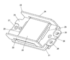
撮像素子20は、図2及び図3に示すように、鏡胴本体部5の下端部に取り付けられている。以下、図4を参照して撮像素子20の取付構造について具体的に説明する。図4は、鏡胴本体部5の下端部に取り付けられる撮像素子ユニットを示した斜視図である。
As shown in FIGS. 2 and 3, the
撮像素子20が回路基板21の上に実装されている。回路基板21は樹脂基板、ガラス基板、セラミック基板その他剛性のある基板である。なお、回路基板21が可撓性のあるフレキシブル基板であってもよい。
The
この撮像素子20が金属製のブラケット22によって囲繞されている。ブラケット22は、撮像素子20が実装された回路基板を鏡胴本体部5の下端部に取り付けるための部材であり、中央部に撮像素子20が挿入可能な開口が形成された枠状の金属板の前片部23及び後片部24を左片部25及び右片部26に対して略垂直に折り曲げてなるものである。ブラケット22の前片部23、後片部24が撮像素子20の前縁、後縁にそれぞれ沿い、前片部23及び後片部24が撮像素子20を挟んで前後に相対している。また、ブラケット22の左片部25、右片部26が撮像素子20の左縁、右縁にそれぞれ沿い、左片部25及び右片部26が撮像素子20を挟んで左右に相対している。
The
ブラケット22の左片部25及び右片部26が回路基板21に向き合った状態で、左片部25及び右片部26が回路基板21に固着されている。具体的には、左片部25及び右片部26の内縁部と撮像素子20との間に接着剤29が注入され、接着剤29によって左片部25及び右片部26が撮像素子20及び回路基板21に接着されている。
The
ブラケット22が回路基板21に接着された状態においては、前片部23が回路基板21の前縁に沿って左片部25及び右片部26に対して折り曲げられており、後片部24が回路基板21の後縁に沿って左片部25及び右片部26に対して折り曲げられている。そのため、前片部23及び後片部24が回路基板21に対して立った状態となっている。回路基板21の前縁から前に延び出た前片部23、回路基板21の後縁から後ろに延び出た後片部24が折り曲げられることによって、ブラケット22の前後長が回路基板21及び撮像素子20の前後長に合っている。
In a state where the
図3等示すように、撮像素子20の受光面(上面)が鏡胴本体部5の下部開口5aに向き合っている。撮像素子20の受光面の縁部分がクッションカバー40によって覆われ、クッションカバー40が撮像素子20と鏡胴本体部5の間に挟まれている。
As shown in FIG. 3 and the like, the light receiving surface (upper surface) of the
撮像素子20が鏡胴本体部5の下部開口5aに向き合った状態で、ブラケット22が鏡胴本体部5の下部に結合されている。ここで、図4に示すように、ブラケット22の右片部26に通し穴28が形成されており、図2に示すように、ネジ32が通し穴28に挿入されて、鏡胴本体部5の下端部に締め付けられている。同様に、左片部25に形成された通し穴27にネジが挿入され、そのネジが鏡胴本体部5の下端部に締め付けられている。
The
ブラケット22が鏡胴本体部5に取り付けられた状態にあっては、ブラケット22の前片部23が鏡胴本体部5の前面5bに対して平行であり、後片部24が鏡胴本体部5の後面5cに対して平行である。また、図1に示すように、回路基板21が筐体2の前面2aに対して垂直になるように配置され、撮像素子20の受光面も筐体2の前面2aに対して垂直となっている。
When the
組み付け方法について説明する。
撮像素子20を回路基板21に実装する。
また、矩形枠状金属板の前片部23及び後片部24を左片部25及び右片部26に対して垂直に折り曲げ、ブラケット22を成型する。
次に、ブラケット22の左片部25及び右片部26を回路基板21に対向させ、撮像素子20がブラケット22の前片部23、後片部24、左片部25及び右片部26によって囲まれるように位置合わせする。
次に、左片部25及び右片部26の内縁部と撮像素子20との間に接着剤29を注入する。接着剤29が硬化することによって、撮像素子20及び回路基板21がブラケット22に接着される。
The assembly method will be described.
The
Further, the
Next, the
Next, an adhesive 29 is injected between the inner edge portions of the
次に、屈曲光学系10が組み付けられた鏡胴4に撮像素子20を取り付ける。即ち、撮像素子20の受光面の縁部分をクッションカバー40で覆い、撮像素子20の受光面を鏡胴本体部5の下部開口5aに向け、ブラケット22の通し穴27,28にネジ32を通して、ネジ32を鏡胴本体部5の下部に締め付ける。
Next, the
次に、鏡胴4を撮像素子20及び屈曲光学系10ごと筐体2内に収容し、これらを固定する。
Next, the lens barrel 4 is housed in the
以上のように、本実施形態によれば、ブラケット22の前片部23が左片部25及び右片部26に対して折り曲げられているから、前片部23が鏡胴本体部5の前面5bから前にはみ出る長さを短くすることができる。同様に、ブラケット22の後片部24が左片部25及び右片部26に対して折り曲げられているから、後片部24が鏡胴本体部5の後面5cから後ろにはみ出る長さを短くすることができる。よって、ブラケット22の前後長を短くすることができ、デジタルカメラ1の前後方向の厚さを薄くすることができる。
As described above, according to the present embodiment, since the
一方、ブラケット22の前後長が短くなったものとしても、前片部23及び後片部24が左片部25と右片部26の間に掛け渡されているから、ブラケット22の強度低下も招かない。それどころか、前片部23及び後片部24が左片部25及び右片部26に対して立てた状態となっているから、ブラケット22の上下方向(左片部25及び右片部26の厚み方向)の剛性が向上する。従って、撮像素子20を安定した状態で取り付けることができる。
On the other hand, even if the longitudinal length of the
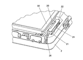
<第2の実施の形態>
上記第1の実施形態では、前片部23及び後片部24の両方が上に折り曲げられていたが、前片部23と後片部24のうち一方が上に折り曲げられ、他方が下に折り曲げられていてもよい。例えば、図5に示すように、前片部23が上に折り曲げられ、後片部24が下に折り曲げられていると、図6に示すように、筐体2の後面側に設けられた他の部品50(例えば、液晶ディスプレイパネル等のモニタ)から逃げるようにして後片部24を配置することができる。他の部品50が、液晶ディスプレイパネル等のモニタである場合には、カメラ筐体2の背面側に設けるモニタを大型のものにすることができる。その他部分については、第1実施形態の場合と同様であるので、それらの説明を省略する。
<Second Embodiment>
In the first embodiment, both the
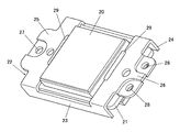
<第3の実施の形態>
図7に示すように、前片部23と後片部24の両方が下に折り曲げられていてもよい。この場合、回路基板21が前片部23と後片部24の間に配置されることになる。その他部分については、第1実施形態の場合と同様であるので、それらの説明を省略する。
<Third Embodiment>
As shown in FIG. 7, both the
なお、本発明は、上記実施形態に限定されることなく、本発明の趣旨を逸脱しない範囲において、種々の改良並びに設計の変更を行っても良い。
上記各実施形態では、ブラケット22の左片部25及び右片部26と回路基板21との接合が接着によるものであったが、ねじの締結によるものでもよいし、爪を引っかけることによるものでもよい。
また、上記各実施形態ではブラケット22と鏡胴4の固定にはネジ32を用いたが、接着、爪等を用いてもよい。また、上記各実施形態では左片部25及び右片部26にネジ32を通してブラケット22を鏡胴4に固定したが、第1の実施形態のように、前片部23及び後片部24が鏡胴本体部5側に折り曲げられている場合には、ネジ結合その他の接合によって前片部23、後片部24を鏡胴4に固着してもよい。
また、上記各実施形態ではプリズム12によって光軸が屈曲されているが、鏡面によって光軸が屈曲されてもよい。
また、上記各実施形態では鏡胴4の鏡胴本体部5が上下方向に延在しているが、鏡胴本体部5が左右方向に延在してもよい。この場合、プリズム12の入射面13が前方を向いているのは上記各実施形態と同様であるが、プリズム12の出射面15が左又は右を向いており、撮像素子20の受光面も右又は左を向いて出射面15に対向し、レンズ16の光軸が左右方向に沿っていることが異なる。
また、上記各実施形態では、デジタルカメラを例に説明したが、本発明の撮像装置は、カメラ機能付き携帯電話機やカメラ機能付きPDA等の携帯型電子機器は勿論のこと、デジタルカメラ機能を備え且つ薄型化が要求される電子機器であればよい。
The present invention is not limited to the above-described embodiment, and various improvements and design changes may be made without departing from the spirit of the present invention.
In each of the above embodiments, the joining of the
In each of the above embodiments, the
In each of the above embodiments, the optical axis is bent by the
Moreover, in each said embodiment, although the lens barrel main-
In each of the above embodiments, the digital camera has been described as an example. However, the imaging apparatus of the present invention has a digital camera function as well as a portable electronic device such as a mobile phone with a camera function and a PDA with a camera function. Any electronic device that is required to be thin can be used.
1 デジタルカメラ(撮像装置)
2 筐体
4 鏡胴
5 鏡胴本体部
10 屈曲光学系
20 撮像素子
21 回路基板
22 ブラケット
23 前片部
24 後片部
25 左片部
26 右片部
1 Digital camera (imaging device)
2 Housing 4
Claims (8)
枠状板が、その開口に位置する前記撮像素子を囲繞し、
前記枠状板の開口を挟んで相対する2辺部分が他の部分に対して折り曲げられ、前記他の部分が前記基板の上に接合され、
前記撮像素子が鏡胴の開口に向き合った状態で前記枠状板が前記鏡胴に取り付けられて
いることを特徴とする撮像素子の取付構造。 The image sensor is mounted on the substrate,
A frame-shaped plate surrounds the image sensor located in the opening ;
The two sides facing each other across the opening of the frame-shaped plate are bent with respect to the other part, and the other part is bonded onto the substrate,
A mounting structure for an image sensor, wherein the frame plate is attached to the lens barrel with the image sensor facing the opening of the lens barrel.
前記筐体内に収容された鏡胴と、
前記筐体内に収容された基板と、
前記鏡胴の開口に向き合い、前記基板の上に実装された撮像素子と、
前記鏡胴に取り付けられた枠状板であって、その開口に位置する前記撮像素子を囲繞する枠状板と、
前記鏡胴内に取り付けられ、前記筐体の前面側から取り込んだ像を前記鏡胴の開口を通じて前記撮像素子に結像する光学系と、を備え、
前記枠状板の開口を挟んで相対する前片部及び後片部が他の部分に対して折り曲げられ、前記他の部分が前記基板の上に接合されている
ことを特徴とする撮像装置。 A housing,
A lens barrel housed in the housing;
A substrate housed in the housing;
An image sensor facing the opening of the lens barrel and mounted on the substrate;
A frame-shaped plate mounted in front Symbol barrel, a frame-shaped plate surrounding the imaging element located in the opening,
An optical system mounted in the lens barrel and forming an image captured from the front side of the housing on the image sensor through the opening of the lens barrel, and
An imaging apparatus, wherein a front piece portion and a rear piece portion opposed to each other across an opening of the frame-shaped plate are bent with respect to another portion, and the other portion is bonded onto the substrate.
Priority Applications (1)
| Application Number | Priority Date | Filing Date | Title |
|---|---|---|---|
| JP2008322108A JP5157877B2 (en) | 2008-12-18 | 2008-12-18 | Imaging element mounting structure and imaging apparatus |
Applications Claiming Priority (1)
| Application Number | Priority Date | Filing Date | Title |
|---|---|---|---|
| JP2008322108A JP5157877B2 (en) | 2008-12-18 | 2008-12-18 | Imaging element mounting structure and imaging apparatus |
Publications (3)
| Publication Number | Publication Date |
|---|---|
| JP2010147753A JP2010147753A (en) | 2010-07-01 |
| JP2010147753A5 JP2010147753A5 (en) | 2011-10-13 |
| JP5157877B2 true JP5157877B2 (en) | 2013-03-06 |
Family
ID=42567725
Family Applications (1)
| Application Number | Title | Priority Date | Filing Date |
|---|---|---|---|
| JP2008322108A Expired - Fee Related JP5157877B2 (en) | 2008-12-18 | 2008-12-18 | Imaging element mounting structure and imaging apparatus |
Country Status (1)
| Country | Link |
|---|---|
| JP (1) | JP5157877B2 (en) |
Families Citing this family (3)
| Publication number | Priority date | Publication date | Assignee | Title |
|---|---|---|---|---|
| JP5693085B2 (en) * | 2010-08-18 | 2015-04-01 | キヤノン株式会社 | Imaging device |
| JP5575101B2 (en) * | 2011-12-26 | 2014-08-20 | キヤノン株式会社 | Image pickup device holding device, lens barrel, and image pickup device |
| JP6639290B2 (en) * | 2016-03-18 | 2020-02-05 | キヤノン株式会社 | Imaging device |
Family Cites Families (4)
| Publication number | Priority date | Publication date | Assignee | Title |
|---|---|---|---|---|
| JP2004320169A (en) * | 2003-04-11 | 2004-11-11 | Miyota Kk | Solid-state imaging apparatus and manufacturing method thereof, and manufacturing tool |
| JP2005257784A (en) * | 2004-03-09 | 2005-09-22 | Olympus Corp | Camera, lens device and mobile type information apparatus |
| JP2006194957A (en) * | 2005-01-11 | 2006-07-27 | Fujinon Corp | Imaging apparatus, lens barrel and circuit board |
| JP3812587B2 (en) * | 2005-06-09 | 2006-08-23 | 三菱電機株式会社 | Imaging device |
-
2008
- 2008-12-18 JP JP2008322108A patent/JP5157877B2/en not_active Expired - Fee Related
Also Published As
| Publication number | Publication date |
|---|---|
| JP2010147753A (en) | 2010-07-01 |
Similar Documents
| Publication | Publication Date | Title |
|---|---|---|
| JP5000428B2 (en) | Imaging device | |
| JP4917060B2 (en) | Imaging unit and portable electronic device | |
| TWI328712B (en) | ||
| US8836856B2 (en) | Imaging unit with prisms and image sensor | |
| JP4555732B2 (en) | Imaging device | |
| JP4769908B2 (en) | Imaging device | |
| JP2016057468A (en) | Bending imaging device | |
| JP7057516B2 (en) | Lens drive device, camera module, and camera mount device | |
| JP2009135853A (en) | Camera module and imaging apparatus | |
| JP6172993B2 (en) | Imaging device | |
| JP5157877B2 (en) | Imaging element mounting structure and imaging apparatus | |
| JP4391838B2 (en) | Digital camera | |
| JP5082325B2 (en) | Imaging device | |
| JP2006079009A (en) | Focal plane shutter and imaging apparatus | |
| KR101147782B1 (en) | Camera module | |
| TW201930999A (en) | Camera device | |
| JP4923575B2 (en) | camera | |
| JP5187181B2 (en) | Imaging device | |
| JP5151960B2 (en) | Imaging element mounting member and imaging apparatus | |
| JP4282383B2 (en) | Optical equipment | |
| JP2020003546A (en) | Image capturing device | |
| JP2005257784A (en) | Camera, lens device and mobile type information apparatus | |
| JP4797047B2 (en) | Lens barrel | |
| JP7237720B2 (en) | Imaging device | |
| JP4921728B2 (en) | Camera finder device |
Legal Events
| Date | Code | Title | Description |
|---|---|---|---|
| A521 | Request for written amendment filed |
Free format text: JAPANESE INTERMEDIATE CODE: A523 Effective date: 20110831 |
|
| A621 | Written request for application examination |
Free format text: JAPANESE INTERMEDIATE CODE: A621 Effective date: 20110831 |
|
| RD02 | Notification of acceptance of power of attorney |
Free format text: JAPANESE INTERMEDIATE CODE: A7422 Effective date: 20110831 |
|
| A977 | Report on retrieval |
Free format text: JAPANESE INTERMEDIATE CODE: A971007 Effective date: 20120910 |
|
| A131 | Notification of reasons for refusal |
Free format text: JAPANESE INTERMEDIATE CODE: A131 Effective date: 20120918 |
|
| A521 | Request for written amendment filed |
Free format text: JAPANESE INTERMEDIATE CODE: A523 Effective date: 20121015 |
|
| TRDD | Decision of grant or rejection written | ||
| A01 | Written decision to grant a patent or to grant a registration (utility model) |
Free format text: JAPANESE INTERMEDIATE CODE: A01 Effective date: 20121113 |
|
| A61 | First payment of annual fees (during grant procedure) |
Free format text: JAPANESE INTERMEDIATE CODE: A61 Effective date: 20121126 |
|
| R150 | Certificate of patent or registration of utility model |
Ref document number: 5157877 Country of ref document: JP Free format text: JAPANESE INTERMEDIATE CODE: R150 Free format text: JAPANESE INTERMEDIATE CODE: R150 |
|
| FPAY | Renewal fee payment (event date is renewal date of database) |
Free format text: PAYMENT UNTIL: 20151221 Year of fee payment: 3 |
|
| LAPS | Cancellation because of no payment of annual fees |