JP5157135B2 - Endless belt, fixing device, and image forming apparatus - Google Patents
Endless belt, fixing device, and image forming apparatus Download PDFInfo
- Publication number
- JP5157135B2 JP5157135B2 JP2006305164A JP2006305164A JP5157135B2 JP 5157135 B2 JP5157135 B2 JP 5157135B2 JP 2006305164 A JP2006305164 A JP 2006305164A JP 2006305164 A JP2006305164 A JP 2006305164A JP 5157135 B2 JP5157135 B2 JP 5157135B2
- Authority
- JP
- Japan
- Prior art keywords
- belt
- endless belt
- bent
- resin
- fixing
- Prior art date
- Legal status (The legal status is an assumption and is not a legal conclusion. Google has not performed a legal analysis and makes no representation as to the accuracy of the status listed.)
- Expired - Fee Related
Links
Images


Description
本発明は、エンドレスベルト関する。また本発明は、該エンドレスベルトを使用した定着装置及び画像形成装置に関する。 The present invention relates to an endless belt. The present invention also relates to a fixing device and an image forming apparatus using the endless belt.
電子写真方式を用いた複写機、プリンタ等の画像形成装置では、例えばドラム状に形成された感光体(感光体ドラム)を一様に帯電し、この感光体ドラムを画像情報に基づいて制御された光で露光して感光体ドラム上に静電潜像を形成する。そして、この静電潜像をトナーによって可視像(トナー像)とし、このトナー像を感光体ドラム上から中間転写ベルトに一次転写したのちさらに中間転写ベルトから記録紙に二次転写した後、定着装置によってこのトナー像を記録紙に定着している。 In an image forming apparatus such as a copying machine or a printer using an electrophotographic system, for example, a photosensitive member (photosensitive drum) formed in a drum shape is uniformly charged, and the photosensitive drum is controlled based on image information. An electrostatic latent image is formed on the photosensitive drum by exposure with the exposed light. Then, the electrostatic latent image is converted into a visible image (toner image) with toner, and the toner image is primarily transferred from the photosensitive drum to the intermediate transfer belt, and then secondarily transferred from the intermediate transfer belt to the recording paper. The toner image is fixed on the recording paper by a fixing device.
従来の定着装置としては、例えば加熱源を有する回転可能な加熱定着ロールと、この加熱定着ロールに圧接し且つ加熱ロールと共に従動する無端ベルトと、この無端ベルトの内側に配設されて、前記無端ベルトを加熱ロールに押圧させ且つ前記無端ベルトと加熱定着ロールとの間に接触ニップ域を形成する押圧部材と、前記エンドレスベルトの両端部の内側に嵌合された状態に配設され、当該前記エンドレスベルトの内面を回転自在にガイドするベルトガイド部材とを備え、このニップ部にシートを通過させることで、当該シート上の未定着トナー像を加熱加圧定着するようにしたものが知られている、この種の定着装置(ベルトニップ方式)においては、エンドレスベルトは両端部のガイド部材によりウォークを制御されているが、定着装置の長期に亘る使用によって、エンドレスベルトが両端部に配置されたベルト規制部材に突き当たる回数が増えると、エンドレスベルトの端部がベルト規制部材との摺動によって摩耗し、エンドレスベルトの端部に亀裂が生じたり、最悪の場合には端部破断に至る可能性もあった。
このようなベルト端部の亀裂や破断の発生は前記ベルトニップ方式の定着装置に限らず、エンドレスベルトを使用する定着システムにおいては共通の課題となっており、ベルト駆動システムでの制御システムの改善や、ベルト自身の耐久性を上げることよって改善が図られている。
As a conventional fixing device, for example, a rotatable heat fixing roll having a heating source, an endless belt which is in pressure contact with the heat fixing roll and is driven with the heat roll, and an inner end of the endless belt, the endless belt is arranged. A pressing member that presses the belt against the heating roll and forms a contact nip region between the endless belt and the heating fixing roll, and is disposed in a state of being fitted inside both end portions of the endless belt, And a belt guide member that rotatably guides the inner surface of the endless belt, and by passing the sheet through this nip portion, an unfixed toner image on the sheet is heated and pressed and fixed. In this type of fixing device (belt nip type), the endless belt is controlled in its walk by guide members at both ends. If the number of times the endless belt hits the belt regulating member disposed at both ends increases due to the long-term use of the endless belt, the end of the endless belt will wear due to sliding with the belt regulating member, and the end of the endless belt will crack. There is a possibility that the end portion breaks in the worst case.
The occurrence of such cracks and breaks at the end of the belt is not limited to the fixing device of the belt nip method, but is a common problem in a fixing system using an endless belt. Improvement of the control system in the belt drive system In addition, improvement is achieved by increasing the durability of the belt itself.
例えば、ベルト駆動システムの改善を図ったものとしては、ベルト規制部材のベルト部材のエッジ面との当接部が弾性変形可能に構成されたもの(例えば、特許文献1参照。)、また、ベルト自身の耐久性を向上させることよって改善を図ったものとしては、ベルト両端周縁部の外表面及び/又は内表面に耐熱性コート層を設けたりあるいは耐熱性テープを貼り付けたもの(例えば、特許文献2参照。)、ベルト金属層の両端部の厚さを中央部の膜厚より厚くしたもの(例えば、特許文献3参照。)、さらに、ベルト外周層にゴム層を有し、前記ゴム層にてベルト端部を覆ったもの(例えば、特許文献4参照。)等がすでに提案されている。
しかしながら、上記従来技術の場合には、次のような問題点を有している。
すなわち、ベルト駆動システムでの改善を図ったものでは単純な突き当てタイプのガイドに比べコストアップとなってしまい好ましくない。従って、ベルト自身の耐久性を向上することによって改善することが好ましく、ベルトの膜厚を厚くすることが最も効果的ではあるが、コストアップやベルトの可撓性が低下することによる用紙の剥離不良などが発生してしまう。またベルト端部の膜厚のみを精度維持しつつ厚くすると製造コストがアップしてしまう。さらに、ベルト端部に耐熱性コート層や耐熱テープの貼り付け又はシリコーンゴム等の補強リブの追加では、ガイドとの回転摺動に対する耐摩耗性や繰り返し疲労耐久性が不十分でエンドレスベルト両端部に設けられたベルトガイドとの回転摺動抵抗を長期間に渡って安定して維持することができない。
However, the conventional technique has the following problems.
That is, the improvement in the belt drive system is not preferable because the cost is increased as compared with a simple butting type guide. Therefore, it is preferable to improve by improving the durability of the belt itself, and it is most effective to increase the film thickness of the belt, but the paper is peeled off due to the increase in cost and the decrease in flexibility of the belt. Defects will occur. If the thickness is increased while maintaining only the film thickness at the belt end, the manufacturing cost will increase. Furthermore, if a heat-resistant coating layer or heat-resistant tape is affixed to the end of the belt or a reinforcing rib such as silicone rubber is added, the wear resistance against repeated sliding with the guide and repeated fatigue durability are insufficient. Rotational sliding resistance with the belt guide provided in can not be stably maintained over a long period of time.
本発明は、複雑なシステムを要せず、薄肉で均一な膜厚のエンドレスベルトの片側又は両側の端部の強度アップを図り、エンドレスベルトの挫掘又はエンドレスベルト端部の摩耗変形やベルト破断につながる亀裂が発生するのを確実に防止することができる低コストのエンドレスベルトを提供することにある。またさらには前記エンドレスベルトを使用した耐久性の高い電子写真用の定着装置及び画像形成装置を提供することにある。 The present invention does not require a complicated system, increases the strength of one or both ends of the endless belt with a thin and uniform film thickness, excavates the endless belt, wears or deforms the endless belt, or breaks the belt. It is an object of the present invention to provide a low-cost endless belt that can surely prevent the occurrence of cracks that lead to. Still another object of the present invention is to provide a highly durable electrophotographic fixing device and image forming apparatus using the endless belt.
本発明者等は、上記目的を達成するためにエンドレスベルト及び電子写真定着装置について研究を重ねた結果、本発明を完成するに至った。即ち本発明は、
<1> 耐熱性樹脂を含有してなる基層、及び前記基層上に熱可塑性樹脂を含有してなる被覆層を有するベルト本体と、
前記ベルト本体の片側又は両側の端部に、外側に向かって90°以上折り曲げられてなる折り曲げ部と、
前記ベルト本体と前記折り曲げ部との間を接合する接合部であって、前記前記熱可塑性樹脂により形成されてなる接合部と、
を有することを特徴とするエンドレスベルトである。
The inventors of the present invention have conducted research on an endless belt and an electrophotographic fixing device in order to achieve the above object, and as a result, the present invention has been completed. That is, the present invention
<1> a belt main body having a base layer containing a heat-resistant resin, and a coating layer containing a thermoplastic resin on the base layer;
On one or both sides of an end portion of the belt body, a bent portion becomes bent 90 ° or more toward the outer side,
A joint that joins between the belt body and the bent portion, the joint formed by the thermoplastic resin;
It is an endless belt characterized by having .
<2> 前記接合部は補強部材を含むことを特徴する前記<1>に記載のエンドレスベルトである。 <2> The endless belt according to < 1 > , wherein the joint includes a reinforcing member.
<3> 定着部材と、
耐熱性樹脂を含有してなる基層、及び前記基層上に熱可塑性樹脂を含有してなる被覆層を有するベルト本体と、前記ベルト本体の片側又は両側の端部に、外側に向かって90°以上折り曲げられてなる折り曲げ部と、前記ベルト本体と前記折り曲げ部との間を接合する接合部であって、前記前記熱可塑性樹脂により形成されてなる接合部と、を有するエンドレスベルトと、
該エンドレスベルトの内側に配置され、該エンドレスベルトを前記定着部材に圧接させて前記定着部材と前記エンドレスベルトとの接触部分を形成する圧力部材と、
を有することを特徴とする定着装置である。
< 3 > a fixing member;
Base layer comprising a heat-resistant resin, and a belt body having a coating layer containing a thermoplastic resin on the base layer, the end portion of one or both sides of the belt body, toward the outer side 90 ° An endless belt having a bent portion that is bent as described above, and a bonded portion that joins between the belt main body and the bent portion, and is formed of the thermoplastic resin ,
A pressure member that is disposed inside the endless belt and that presses the endless belt against the fixing member to form a contact portion between the fixing member and the endless belt;
The fixing device is characterized by comprising:
<4> 像担持体と、該像担持体表面を帯電させる帯電手段と、前記像担持体表面に潜像を形成する潜像形成手段と、前記潜像をトナーにより現像してトナー像を形成する現像手段と、前記トナー像を記録媒体に転写する転写手段と、前記トナー像を記録媒体に加熱定着させる定着手段とを有し、
前記定着手段は、
定着部材と、
耐熱性樹脂を含有してなる基層、及び前記基層上に熱可塑性樹脂を含有してなる被覆層を有するベルト本体と、前記ベルト本体の片側又は両側の端部に、外側に向かって90°以上折り曲げられてなる折り曲げ部と、前記ベルト本体と前記折り曲げ部との間を接合する接合部であって、前記前記熱可塑性樹脂により形成されてなる接合部と、を有するエンドレスベルトと、
該エンドレスベルトの内側に配置され、該エンドレスベルトを前記定着部材に圧接させて前記定着部材と前記エンドレスベルトとの接触部分を形成する圧力部材と、
を有する定着装置を備えることを特徴とする画像形成装置である。
< 4 > An image carrier, a charging unit for charging the surface of the image carrier, a latent image forming unit for forming a latent image on the surface of the image carrier, and developing the latent image with toner to form a toner image. Developing means, transfer means for transferring the toner image to a recording medium, and fixing means for heat-fixing the toner image on the recording medium,
The fixing means is
A fixing member;
Base layer comprising a heat-resistant resin, and a belt body having a coating layer containing a thermoplastic resin on the base layer, the end portion of one or both sides of the belt body, toward the outer side 90 ° An endless belt having a bent portion that is bent as described above, and a bonded portion that joins between the belt main body and the bent portion, and is formed of the thermoplastic resin ,
A pressure member that is disposed inside the endless belt and that presses the endless belt against the fixing member to form a contact portion between the fixing member and the endless belt;
An image forming apparatus comprising a fixing device having the above.
本発明によれば、複雑なシステムを要せず、薄肉で均一な膜厚のエンドレスベルトの片側又は両側の端部の強度アップを図り、エンドレスベルトの挫掘又はエンドレスベルト端部の摩耗変形やベルト破断につながる亀裂が発生するのを確実に防止することができる低コストのエンドレスベルトを提供することができる。
また、本発明によれば、前記エンドレスベルトを使用した耐久性の高い電子写真用の定着装置並びに画像形成装置を提供することができる。
According to the present invention, a complicated system is not required, the strength of one end or both ends of the endless belt having a thin and uniform film thickness is increased, and the endless belt is dug or worn and deformed at the end of the endless belt. It is possible to provide a low-cost endless belt that can surely prevent the occurrence of cracks that lead to belt breakage.
In addition, according to the present invention, it is possible to provide a highly durable electrophotographic fixing device and an image forming apparatus using the endless belt.
以下、本発明の実施の形態について図面を参照して詳細に説明する。
まず、本発明のエンドレスベルトを説明し、次にそれを用いた本発明の定着装置並びに本発明の画像形成装置について説明する。
Hereinafter, embodiments of the present invention will be described in detail with reference to the drawings.
First, the endless belt of the present invention will be described, and then the fixing device of the present invention and the image forming apparatus of the present invention using the belt will be described.
<エンドレスベルト>
本発明のエンドレスベルトは、ベルト本体の軸方向における片側又は両側の端部が、ベルト本体の外側又は内側に向かって90°以上折り曲げられてなる折り曲げ部を有することを特徴としている。
但し、本発明のエンドレスベルトは、耐熱性樹脂を含有してなる基層、及び前記基層上に熱可塑性樹脂を含有してなる被覆層を有するベルト本体と、ベルト本体の片側又は両側の端部に、外側に向かって90°以上折り曲げられてなる折り曲げ部と、前記ベルト本体と前記折り曲げ部との間を接合する接合部であって、前記前記熱可塑性樹脂により形成されてなる接合部と、を有するエンドレスベルトが採用される。
<Endless belt>
The endless belt of the present invention is characterized in that one or both ends in the axial direction of the belt main body have a bent portion that is bent by 90 ° or more toward the outer side or the inner side of the belt main body.
However, the endless belt of the present invention includes a belt main body having a base layer containing a heat-resistant resin, and a coating layer containing a thermoplastic resin on the base layer, and one or both ends of the belt main body. A bent portion that is bent by 90 ° or more toward the outside, and a bonded portion that joins between the belt body and the bent portion, the bonded portion formed by the thermoplastic resin. The endless belt is used .
本発明のエンドレスベルトは端部に対して折り曲げ加工を施すことにより製造されるが、加工前のエンドレスベルトとしては、少なくともゴム以外の耐熱性樹脂を1層以上積層してなるエンドレスベルトであって、単層構造であってもよいし、多層構造であってもよい。またその形状、大きさ等については特に制限はないが、耐熱性樹脂部分の折り曲げ加工を施した際の拡張率が樹脂の引っ張り破断伸び未満であることが必要である。
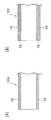
図1は、本発明のエンドレスベルトの加工前に係る(A)基層12のみからなるもの、(B)基層12上に熱可塑性樹脂を含有してなる被覆層14を形成してなるもの、の例を示す断面図である。本発明のエンドレスベルトは、図1の状態のエンドレスベルトの片側又は両側の端部を折り曲げてなる。
The endless belt of the present invention is manufactured by bending the end portion. The endless belt before processing is an endless belt in which at least one heat-resistant resin other than rubber is laminated. A single layer structure or a multilayer structure may be used. The shape, size, etc. are not particularly limited, but it is necessary that the expansion rate when the heat-resistant resin portion is bent is less than the tensile elongation at break of the resin.
FIG. 1 shows (A) the
本発明においては、ベルト本体の端部に折り曲げ加工を施すことによって、ベルト本体の端部の切り放し面とベルトガイドの摺動面との直接接触がなくなると共に、さらに折り曲げ部と非折り曲げ部(ベルト本体)とを接合したり、あるいはさらに補強部材を追加したりすることによって、エンドレスベルトの端部が大幅に補強され、エンドレスベルトの端部の摩耗変形やベルト破断につながる亀裂の発生を低コストで効果的に防止することができる。
なお、本発明のエンドレスベルトとして、ベルト本体の基層が耐熱性樹脂からなるエンドレスベルトは両端部のベルトガイドによりウォークを制御されている定着システム以外の定着システムにおいてもエンドレスベルトの端部の耐久性向上に対して十分な効果を奏する。また更には、同様に耐熱性樹脂からなるエンドレスベルトを使用している中間転写ベルトの端部の補強に対しても有効で、本発明のエンドレスベルトによれば、エンドレスベルトの端部全周に渡って連続した切れ目のない補強部を設けることが可能で、補強部材あるいは蛇行防止ガイド部材の接合部の段差や剥がれに起因する故障の発生を防止することができる。
In the present invention, by subjecting the end of the belt body to bending, there is no direct contact between the cut-out surface of the end of the belt body and the sliding surface of the belt guide. The end of the endless belt is greatly reinforced by joining the main body to the main body) or by adding a reinforcing member, resulting in low-cost cracking that leads to wear deformation and belt breakage of the endless belt. Can be effectively prevented.
As an endless belt according to the present invention, the endless belt whose base layer is made of a heat-resistant resin has durability at the end of the endless belt even in a fixing system other than the fixing system in which the walk is controlled by belt guides at both ends. There is a sufficient effect for improvement. Furthermore, it is also effective for reinforcing the end of the intermediate transfer belt that similarly uses an endless belt made of a heat-resistant resin. According to the endless belt of the present invention, It is possible to provide a continuous and continuous reinforcing portion, and it is possible to prevent the occurrence of a failure due to a step or peeling at the joint portion of the reinforcing member or the meandering prevention guide member.
本発明において前記折り曲げ部は、ベルト本体の端部を折り曲げられてなるが、折り曲げられるベルト本体の長さは、0.2〜10mmが好ましく、0.5〜5mmがより好ましい。
また、前記折り曲げ部は、既述の通り、ベルト本体の端部が外側又は内側に向かって90°以上折り曲げられてなるが、当該角度としては、外側に折り曲げられる場合は、120〜180°が好ましく、150〜180°がより好ましい。また、内側に折り曲げられる場合は、160〜180°が好ましく、170〜180°がより好ましい。また90°未満の折り曲げ角度では、外側に折り曲げた場合には、ベルト本体の端部の切り放し面とベルトガイドの横ずれを規制するベルトガイド部材の面とが直接接触すると共に、ベルトスラスト方向(回転方向と垂直方向)への力が加わりベルト本体の端部がベルトガイド部材の垂直面に押し当てられると、ベルト本体の端部に拡張する力が加わり、亀裂が発生してしまい、さらにはベルト破断につながってしまう。また内側に折り曲げた場合にも、ベルト本体の端部の切り放し面とベルトガイド部材の垂直面とが直接接触すると共に、ベルトスラスト方向(回転方向と垂直方向)への力が加わりベルト本体の端部がベルトガイド部材の垂直面に押し当てられると、ベルト本体の端部を内側に向かって収縮させる力が発生し、ベルトガイドのベルトスラスト方向に対して水平な摺動面と強く接触し、接触部での摺動抵抗が増大する結果、エンドレスベルトの回転不良が発生してしまう。さらにはベルト本体の端部の破断につながる亀裂が発生してしまう。
本発明のエンドレスベルトにおいて、前記折り曲げ部は、片側のみに設けても良いが、本発明の効果をより効果的に奏し得る観点から、両側に設けることが好ましい。
In the present invention, the bent portion is formed by bending the end portion of the belt main body, and the length of the belt main body to be bent is preferably 0.2 to 10 mm, and more preferably 0.5 to 5 mm.
Further, as described above, the bent portion is formed by bending the end portion of the belt main body by 90 ° or more toward the outside or the inside, and the angle is 120 to 180 ° when bent to the outside. Preferably, 150 to 180 ° is more preferable. Moreover, when bent inside, 160-180 degrees are preferable and 170-180 degrees are more preferable. Also, at a bending angle of less than 90 °, when bent outward, the cut-out surface of the end of the belt body and the surface of the belt guide member that regulates the lateral displacement of the belt guide are in direct contact with each other and the belt thrust direction (rotation) When the end of the belt body is pressed against the vertical surface of the belt guide member, an expanding force is applied to the end of the belt body, cracking occurs, and the belt It will lead to breakage. Even when the belt is bent inward, the cut-out surface of the end of the belt body and the vertical surface of the belt guide member are in direct contact with each other, and a force in the belt thrust direction (direction perpendicular to the rotational direction) is applied to the end of the belt body. When the part is pressed against the vertical surface of the belt guide member, a force is generated to shrink the end of the belt body inward, and it comes into strong contact with the sliding surface horizontal to the belt thrust direction of the belt guide, As a result of the increase in sliding resistance at the contact portion, rotation failure of the endless belt occurs. Furthermore, a crack that leads to breakage of the end of the belt main body occurs.
In the endless belt of the present invention, the bent portion may be provided only on one side, but is preferably provided on both sides from the viewpoint of more effectively achieving the effects of the present invention.
なお、上述した折り曲げ角度は、エンドレスベルトの軸方向に沿って当該ベルトの中心軸を切断したときの断面を見たとき、ベルトの軸方向の端部がベルト本体に対して折り曲げられる側とは反対側にあたるベルト本体の内壁面の延長線と、ベルト本体側とは反対側にあたる任意の部分での折り曲げ部の接線とでなす角度(鈍角)のうち、180°以内で最大の角度のことを言う。前記延長線と前記接線とが平行な場合は折り曲げ角度は180°となる。具体的には、例えば、図10に示すように、折り曲げ部10Aがベルト本体10の外側に平面で形成されている場合(折り曲げ部が非屈曲して形成されている場合)には、ベルト本体10の内側の平面(内壁面)の延長線と、ベルト本体10の外側の部分での折り曲げ部10Aの平面(外壁面)の延長線との間でなす角度θ(鈍角)が折り曲げ角度となる。折り曲げ角度は、エンドレスベルトの断面の写真を撮り、適宜拡大して解析することで容易に確認することができる。
The above-mentioned bending angle is the side where the end of the belt in the axial direction is bent with respect to the belt body when the cross section when the central axis of the belt is cut along the axial direction of the endless belt. Of the angle (obtuse angle) formed by the extension line of the inner wall surface of the belt body on the opposite side and the tangent line of the bent portion on the opposite side to the belt body side, the maximum angle within 180 ° say. When the extension line and the tangent line are parallel, the bending angle is 180 °. Specifically, for example, as shown in FIG. 10, when the
ここで、折り曲げ部は、外壁面が平面である方(非屈曲させた状態である方)がより容易に製造できるが、曲面であってもよい(屈曲させた状態であってもよい。)。また、折り曲げ部は丸まった形状(例えば、図9参照)や折り込まれた形状であってもよい。丸まった形状や折り込まれた形状の場合、折り曲げ角度は180°であるとみなす。なお、図9は、丸まった形状の折り曲げ部を有するエンドレスベルトの一例を示す断面図であり、10はベルト本体を示し、10Aは折り曲げ部を示し、16は接合部を示す。 Here, the bent portion can be more easily manufactured when the outer wall surface is a flat surface (one that is not bent), but may be a curved surface (may be bent). . Further, the bent portion may have a rounded shape (see, for example, FIG. 9) or a folded shape. In the case of a rounded shape or a folded shape, the bending angle is regarded as 180 °. FIG. 9 is a cross-sectional view showing an example of an endless belt having a bent portion with a rounded shape, where 10 indicates a belt body, 10A indicates a bent portion, and 16 indicates a joint portion.
ところで、ゴム材料などの場合、一般に100%から500%程度あるいはさらにそれ以上の弾性変形を有するのに対し、耐熱性樹脂では弾性変形は数%であり、それ以上に引っ張ると塑性変形してしまう。また引っ張り破断伸びは通常10〜30%程度であり、高いものでも100%程度以下である。このためゴム材料の場合には特殊な加工設備などがなくても容易に端部の破断等がなく折り曲げすることが可能であるのに対して、耐熱性樹脂では一旦塑性変形させてしまうと、ゴムのように元には戻らず、ゴムと同じように折りかえすと端部が割れてしまったり、あるいは割れなくともエッジの外径が折り曲げの根元に対して大きく開いてしまったりして、所望のものを作製することができない。 By the way, in the case of a rubber material, etc., it generally has an elastic deformation of about 100% to 500% or more, whereas the heat-resistant resin has an elastic deformation of several percent, and if it is pulled more than that, it will be plastically deformed. . Further, the tensile breaking elongation is usually about 10 to 30%, and even a high one is about 100% or less. For this reason, in the case of a rubber material, it is possible to easily bend without breakage of the end portion without special processing equipment, etc., whereas once it is plastically deformed with a heat resistant resin, Like rubber, it does not return to its original shape, but if it is folded in the same way as rubber, the end will crack, or the outer diameter of the edge will open greatly with respect to the root of the bending without cracking. Can not be made.
すなわち、耐熱性樹脂を使用したベルト本体に対して折り曲げ加工を施す際、ベルト本体の端部の拡張率が耐熱性樹脂の引っ張り破断伸び以上に拡張されると端部に亀裂が発生しまう。また破断伸び以内であっても、ベルト本体の端部の外径が折り曲げの根元に対して大きく開いてしまう。 That is, when bending the belt main body using the heat resistant resin, if the expansion rate of the end of the belt main body is expanded beyond the tensile breaking elongation of the heat resistant resin, the end is cracked. Even within the elongation at break, the outer diameter of the end portion of the belt main body is greatly opened with respect to the root of bending.
そこで、本発明のベルト本体において基層として耐熱性樹脂を用いる場合、図2に示すように、加工前の外径(φA)に対して加工後の外径(φB)の拡張率が加工樹脂材料の引っ張り破断伸び未満で加工を行うことにより亀裂の発生を回避することができる。また、ベルト本体の端部の外径が折り曲げの根元に対して開かない様にする為には一定の拡張率で折り曲げ加工を施すことが好ましい。
なお、図2は、図1(A)に示すエンドレスベルト10Xの一端を90°外側に折り曲げた状態を示し、図2(B)は図1(A)に示すエンドレスベルト10Yの一端を180°外側に折り曲げた状態を示している。図2において、符合10Aは折り曲げ部である。
Therefore, when a heat resistant resin is used as the base layer in the belt main body of the present invention, as shown in FIG. 2, the expansion ratio of the outer diameter (φB) after processing is larger than the outer diameter (φA) before processing. Generation of cracks can be avoided by carrying out processing at a tensile breaking elongation of less than. Further, in order to prevent the outer diameter of the end portion of the belt main body from opening with respect to the bending base, it is preferable to perform the bending process with a certain expansion rate.
2 shows a state where one end of the
また本発明のエンドレスベルトでは、ベルト本体の端部の折り曲げ加工方法としては、例えば以下の様な加工方法が挙げられる。 In the endless belt of the present invention, examples of the method for bending the end portion of the belt main body include the following processing methods.
加工方法の一例を図3に示した。被加工物であるベルト本体10は非加工側を芯金20に固定され、加工側はベルト本体の外径よりやや大きい金型22に挿入し、この金型22の先端部はベルト本体10の内側の曲げRに対応した凸状のR形状が全周にわたって設けられている。また、金型22はベルト本体の軸方向に対して加工端側からその反対側に移動可能になっている。また、この金型22と反対方向(図3において左側)に、先端部にベルト本体の外面側の曲げRの外周に対応する曲率を有する凹状のR形状を有する金型24が金型20の軸方向に進退可能に設けられている。
An example of the processing method is shown in FIG. The belt
以上の構成において、ベルト本体10に折り曲げ部を形成する手法について説明する。
まず、ベルト本体10の先端部を金型22の先端部より僅かに突出させ、次にこの状態で金型24を押し当て、ベルト本体10の先端部を変形させる。次に金型24の押し当てを解除し金型22を非加工側に僅かに移動させ、再び金型24を押し当てベルト本体10の先端部を変形させる。さらに同様にして前記ベルト本体10の端部の突き出しと金型24の押し当てを繰り返し、ベルト本体10の端部の折り曲げをすることができる。ベルト本体の端部をその内側に折り曲げる場合には、ベルト本体10の内側に金型22を設けることにより可能である。ただし、この場合は金型22の外径は、ベルト本体の内径よりやや小さいものを用いる。
また、いずれの場合でも、金型22を固定しベルト本体を移動させることも可能である。
A method of forming a bent portion in the
First, the front end portion of the belt
In any case, it is also possible to fix the
また、金型24は曲げRに対応した凹部を有するへら状のものでもよく、ベルト本体の突き出しと共にベルト本体の外周を回転させることによってベルト本体の端部を変形させることも可能である。また金型24は先端部をエラストマーマンドレルとし、マンドレル内の液体を加圧し、マンドレル先端を膨らませる(バジル加工)によってベルト本体の端部を変形させることも可能である。
The
また、金型22あるいは金型24には各種加熱手段を設たり、あるいは別途赤外線や加熱空気吹き付けなどによる加熱手段を設け、耐熱性樹脂材料を加熱することにより、引っ張り破断伸び率を大きくした状態で加工を行うことがより好ましい。
In addition, the
ベルト本体の材質としては、公知各種プラスチック材料のものの中から適宜選択して使用することができるが、プラスチック材料のなかでの一般にエンジニアリングプラスチックと呼ばれるものが適しており、例えばフッソ樹脂、ポリイミド(PI)、ポリアミドイミド(PAI)、ポリベンズイミダゾール(PBI)、ポリエーテルエーテルケトン(PEEK)、ポリサルフォン(PSU)、ポリエーテルスルホン(PES)、ポリフェニレンサルファイド(PPS)、ポリエーテルイミド(PEI)、全芳香族ポリエステル(液晶ポリマー)などが好ましい。またこの中でも機械的強度、耐熱性、耐摩耗性、耐薬品性等に優れる熱硬化性ポリイミド、熱可塑性ポリイミド、ポリアミドイミド、ポリエーテルイミド、フッ素樹脂などが好ましい。ベルト本体の厚さは20〜200μmの範囲とすることが好ましく、50〜100μmの範囲とすることがより好ましい。 The material of the belt body can be appropriately selected from various known plastic materials, but among plastic materials, what is generally called engineering plastic is suitable, for example, fluorine resin, polyimide (PI ), Polyamideimide (PAI), Polybenzimidazole (PBI), Polyetheretherketone (PEEK), Polysulfone (PSU), Polyethersulfone (PES), Polyphenylenesulfide (PPS), Polyetherimide (PEI), Perfume Group polyester (liquid crystal polymer) and the like are preferable. Of these, thermosetting polyimides, thermoplastic polyimides, polyamide imides, polyether imides, fluororesins, and the like that are excellent in mechanical strength, heat resistance, wear resistance, chemical resistance, and the like are preferable. The thickness of the belt body is preferably in the range of 20 to 200 μm, and more preferably in the range of 50 to 100 μm.
また、前記ベルト本体の全面又は一部に渡って金属を積層することも可能で、前記金属材料としては特に制限は無く各種金属が適宜使用可能で、例えばSUS、ニッケル、銅、アルミなどが好適に使用可能である。金属の厚さは3〜70μmの範囲とすることが好ましく、5〜40μmの範囲とすることがより好ましい。但し、ベルトとしての可撓性を考慮すると、折り曲げ部にも金属が積層されている場合には金属の厚さはベルト本体の厚さ以下であることが望ましい。 Further, it is possible to laminate a metal over the entire surface or a part of the belt body, and the metal material is not particularly limited, and various metals can be appropriately used. For example, SUS, nickel, copper, aluminum and the like are preferable. Can be used. The thickness of the metal is preferably in the range of 3 to 70 μm, and more preferably in the range of 5 to 40 μm. However, in consideration of flexibility as a belt, it is desirable that the thickness of the metal is equal to or less than the thickness of the belt body when the metal is also laminated at the bent portion.
また、金属以外にあるいは金属層に加えて、ベルト本体の全面又は一部に渡ってゴム材料も積層することが可能で、各種ゴム材料の中から適宜使用可能で例えば、ウレタンゴム、エチレン・プロピレンゴム(EPM)、シリコーンゴム、フッ素ゴム(FKM)などが上げられ、特に耐熱性、加工性に優れたシリコーンゴムが好ましい。ゴム材料の厚さは、30〜500μmの範囲であることが好ましく、100〜300μmの範囲であることがより好ましい。 In addition to the metal or in addition to the metal layer, a rubber material can be laminated over the entire surface or a part of the belt body, and can be appropriately used from various rubber materials. For example, urethane rubber, ethylene / propylene Rubber (EPM), silicone rubber, fluororubber (FKM) and the like can be raised, and silicone rubber excellent in heat resistance and processability is particularly preferable. The thickness of the rubber material is preferably in the range of 30 to 500 μm, and more preferably in the range of 100 to 300 μm.
エンドレスベルトが定着用ベルトとして使用される場合には、ベルト本体の表面離型層として最外層にフッ素樹脂が積層されることが好ましく、例えば、テトラフルオロエチレン−パーフルオロアルキルビニルエーテル共重合体(PFA)、テトラフルオロエチレン−パーフルオロメチルビニルエーテル共重合体(MFA)、テトラフルオロエチレン−パーフルオロエチルビニルエーテル共重合体(EFA)、ポリテトラフルオロエチレン(PTFE)、テトラフルオロエチレン−ヘキサフルオロプロピレン共重合体(FEP)、ポリエチレン−テトラフルオロエチレン(ETFE)、ポリフッ化ビニリデン(PVDF)、ポリクロロ三フッ化エチレン(PCTFE)、フッ化ビニル(PVF)等のフッ素樹脂挙げられ、特に耐熱性、機械特性等の面からポリテトラフルオロエチレン(PTFE)、及びテトラフルオロエチレン−パーフルオロアルキルビニルエーテル共重合体(PFA)テトラフルオロエチレン−パーフルオロメチルビニルエーテル共重合体(MFA)、テトラフルオロエチレン−パーフルオロエチルビニルエーテル(EFA)共重合体あるいはこれらの変性体が好適に用いられる。表面離型層の厚さは5〜200μmの範囲であることが好ましく、10〜100μmの範囲であることがより好ましい。 When an endless belt is used as a fixing belt, a fluororesin is preferably laminated on the outermost layer as a surface release layer of the belt body. For example, a tetrafluoroethylene-perfluoroalkyl vinyl ether copolymer (PFA) ), Tetrafluoroethylene-perfluoromethyl vinyl ether copolymer (MFA), tetrafluoroethylene-perfluoroethyl vinyl ether copolymer (EFA), polytetrafluoroethylene (PTFE), tetrafluoroethylene-hexafluoropropylene copolymer (FEP), polyethylene-tetrafluoroethylene (ETFE), polyvinylidene fluoride (PVDF), polychlorotrifluoride ethylene (PCTFE), vinyl fluoride (PVF), and the like. From the surface of polytetrafluoroethylene (PTFE), tetrafluoroethylene-perfluoroalkyl vinyl ether copolymer (PFA), tetrafluoroethylene-perfluoromethyl vinyl ether copolymer (MFA), tetrafluoroethylene-perfluoroethyl vinyl ether An (EFA) copolymer or a modified product thereof is preferably used. The thickness of the surface release layer is preferably in the range of 5 to 200 μm, and more preferably in the range of 10 to 100 μm.
前記ベルト本体の各層には適宜、導電性、熱伝導性、絶縁性、剥離性、摺動性、補強等の目的に応じて、各種フィラーを添加することも可能である。フィラーとしては層状構造を持った潤滑性フィラー(例えば、二硫化モリブデン、六方晶窒化硼素、マイカ、グラファイト、二硫化二硫化モリブデン、タルク)、導電性を有するフィラー(例えば、カーボンブラック、黒鉛)、耐熱性樹脂を含んで構成されるフィラー(例えば、耐熱性樹脂がイミド系樹脂、アミド系樹脂、及び全芳香族ポリエステル系樹脂から選択されるフィラー:例えばポリイミド、液晶ポリマー、アラミド)、その他(ガラス粉末、珪酸アルミ、炭素繊維、ブロンズ、チタン酸カリウム、酸化チタン、金属粉末、硫酸バリウム、金属酸化物、炭化物、窒化物、ケイ酸塩化合物)などが使用可能である。 Various fillers can be appropriately added to each layer of the belt body in accordance with purposes such as conductivity, thermal conductivity, insulation, peelability, slidability, and reinforcement. As a filler, a lubricating filler having a layered structure (for example, molybdenum disulfide, hexagonal boron nitride, mica, graphite, molybdenum disulfide disulfide, talc), a conductive filler (for example, carbon black, graphite), Filler composed of heat-resistant resin (for example, filler in which the heat-resistant resin is selected from imide resin, amide resin, and wholly aromatic polyester resin: polyimide, liquid crystal polymer, aramid), and others (glass (Powder, aluminum silicate, carbon fiber, bronze, potassium titanate, titanium oxide, metal powder, barium sulfate, metal oxide, carbide, nitride, silicate compound) can be used.
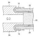
本発明のエンドレスベルトにおいては、ベルト本体と折り曲げ部との間を接合する接合部を有することが好ましい。当該態様では、図4に示すように、折り曲げ部12Aとベルト本体12の外周面又は内周面との隙間に充填物を充填して接合部16を形成する。なお、図4において、(A)はエンドレスベルトの外側に折り曲げ部を有する例であり、(B)は内側に折り曲げ部を有する例であり、いずれも図2と同じ構成要素には同一の符合を付している。
In the endless belt of the present invention, it is preferable to have a joint portion that joins between the belt main body and the bent portion. In this aspect, as shown in FIG. 4, the joint 16 is formed by filling the gap between the
前記接合部をなす充填物としては、各種接着剤、各種未加硫ゴム、各種熱硬化性樹脂、各種熱可塑性樹脂の使用が可能である。また、加熱あるいは加圧によって接着性を発揮するものは隙間に充填後加熱及び必要に応じて加圧することが必要である。また熱可塑性樹脂などにおいては、加圧下で超音波振動を加えることによって発熱融着(超音波融着)させることも可能である。 As the filler forming the joint portion, various adhesives, various unvulcanized rubbers, various thermosetting resins, and various thermoplastic resins can be used. Moreover, what exhibits adhesiveness by heating or pressurization needs to be heated after pressurization in a gap and pressurized as necessary. In addition, a thermoplastic resin or the like can be heat-fusing (ultrasonic fusing) by applying ultrasonic vibration under pressure.
前記接着剤としては、オルガノポリシロキサンを主成分とする縮合硬化型あるいは付加硬化型のシリコーン系接着剤、メチルジメトキシシリル基を末端に持つポリプロピレンオキシド(変性シリコーン)を主成分とする変性シリコーン系接着剤、芳香族複素環ポリマーに属するポリイミド(PI)類の低分子ポリマーを主成分とするポリイミド系接着剤、芳香族複素環ポリマーに属するポリベンズイミダソール(PBI)を主成分とするポリベンズイミダソール接着剤、エポキシ樹脂を主成分とするエポキシ系接着剤、ウレタン樹脂系接着剤、反応性ホットメルト接着剤、ポリウレタン樹脂ホットメルト接着剤、ポリアミド樹脂ホットメルト接着剤、ポリオレフィン樹脂ホットメルト接着剤、クロロプレンゴム系接着剤などが挙げられ、中でも、耐熱性や可撓性の観点から、シリコーン系や変性シリコーン系あるいはポリイミド系の接着剤が好ましい。 Examples of the adhesive include condensation-curing or addition-curing silicone adhesives mainly composed of organopolysiloxane, and modified silicone-based adhesives mainly composed of polypropylene oxide (modified silicone) terminated with a methyldimethoxysilyl group. Agent, polyimide adhesive based on low molecular weight polymer of polyimide (PI) belonging to aromatic heterocyclic polymer, polybenzimidazole (PBI) based on polybenzimidazole belonging to aromatic heterocyclic polymer Imidasol adhesive, epoxy resin based epoxy resin, urethane resin adhesive, reactive hot melt adhesive, polyurethane resin hot melt adhesive, polyamide resin hot melt adhesive, polyolefin resin hot melt adhesive Agents, chloroprene rubber adhesives, etc. In terms of sex, silicone or modified silicone or polyimide-based adhesive is preferred.
また、耐久性や導電性を確保することを狙いとして、前記充填物中に、各種フィラーを添加することも可能である。フィラーとしては層状構造を持った潤滑性フィラー(例えば、二硫化モリブデン、六方晶窒化硼素、マイカ、グラファイト、二硫化モリブデン、タルク)、導電性を有するフィラー(例えば、カーボンブラック、黒鉛)、耐熱性樹脂を含んで構成されるフィラー(例えば、耐熱性樹脂がイミド系樹脂、アミド系樹脂、及び全芳香族ポリエステル系樹脂から選択されるフィラー:例えばポリイミド、液晶ポリマー、アラミド)、その他(ガラス粉末、珪酸アルミ、炭素繊維、ブロンズ、チタン酸カリウム、酸化チタン、金属粉末、硫酸バリウム、金属酸化物、炭化物、窒化物、ケイ酸塩化合物)などが使用可能である。また接合部の加工後に新たに表面層を追加積層することも可能である。
Further, various fillers can be added to the filler for the purpose of ensuring durability and conductivity. As filler, a lubricious filler having a layered structure (for example, molybdenum disulfide, hexagonal boron nitride, mica, graphite, molybdenum disulfide, talc), conductive filler (for example, carbon black, graphite), heat resistance Fillers comprising resin (for example, fillers in which the heat resistant resin is selected from imide resins, amide resins, and wholly aromatic polyester resins: polyimide, liquid crystal polymer, aramid), and others (glass powder, Aluminum silicate, carbon fiber, bronze, potassium titanate, titanium oxide, metal powder, barium sulfate, metal oxide, carbide, nitride, silicate compound) and the like can be used. It is also possible to add a new surface layer after processing the joint.
また、本発明のエンドレスベルトにおいては、ベルト本体は、基層上に熱可塑性樹脂を含有してなる被覆層を有し、前記接合部が該熱可塑性樹脂により形成されてもよい。当該態様では、図5に示すように、ベルト本体の折り曲げにより、折り曲げ部12Aの被覆層14と、ベルト本体12の被覆層14とが接触するが、この折り曲げ部に対して外部から熱や圧力又は超音波振動を加えることで、熱可塑性樹脂からなる被覆層が合一し、接合部16が形成される。なお、図5において、(A)はエンドレスベルトの外側に折り曲げ部を有する例であり、(B)は内側に折り曲げ部を有する例であり、いずれも図1、図2と同じ構成要素には同一の符合を付している。
In the endless belt of the present invention, the belt main body may have a coating layer containing a thermoplastic resin on a base layer, and the joining portion may be formed of the thermoplastic resin. In this aspect, as shown in FIG. 5, the
前記被覆層の熱可塑性樹脂としては、市販の各種熱可塑性樹脂が使用可能であるが、耐熱性を考慮すると、各種フッ素樹脂、熱可塑性ポリイミド(PI)、ポリアミドイミド(PAI)、ポリエーテルイミド(PEI)が適している。また接合部の加工後に新たに表面層を追加積層することも可能である。 As the thermoplastic resin of the coating layer, various commercially available thermoplastic resins can be used, but considering heat resistance, various fluororesins, thermoplastic polyimide (PI), polyamideimide (PAI), polyetherimide ( PEI) is suitable. It is also possible to add a new surface layer after processing the joint.
前記いずれの態様においても、さらなる強度向上の観点から、接合部には補強部材を含むことが好ましい。当該態様では、図6に示すように、折り曲げ部12Aとベルト本体12の外周面又は内周面との隙間に充填物を充填し、さらに当該充填物中に補強部材18を封入して接合部16を形成する。なお、図6において、(A)はエンドレスベルトの外側に折り曲げ部を有する例であり、(B)は内側に折り曲げ部を有する例であり、いずれも図2と同じ構成要素には同一の符合を付している。
In any of the above embodiments, it is preferable that the joint portion includes a reinforcing member from the viewpoint of further improving the strength. In this aspect, as shown in FIG. 6, a filler is filled in a gap between the
前記補強部材としては各種樹脂、ゴム、金属やこれらの複合材料の使用が可能で市販品の中から適宜選ぶことが可能である。また接合部の加工後に新たに表面層を追加積層することも可能である。 As the reinforcing member, various resins, rubbers, metals and composite materials thereof can be used, and can be appropriately selected from commercially available products. It is also possible to add a new surface layer after processing the joint.
また、単層又は複層からなるベルト本体の片側又は両側を、外側又は内側に向かって折り曲げ加工を施した後に、新たにその上にフッ素樹脂をはじめとする各種耐熱性樹脂や各種金属あるいは各種ゴム材料を複数に渡って積層し、エンドレスベルトを形成することも可能である。 In addition, after one side or both sides of the belt body composed of a single layer or multiple layers are bent toward the outside or the inside, a variety of heat resistant resins such as fluororesin, various metals, or various types are newly formed thereon. It is also possible to laminate a plurality of rubber materials to form an endless belt.
<定着装置>
次に、本発明のエンドレスベルトを用いた、本発明の定着装置について説明する。
図7は、本発明の実施の形態に係る定着装置の概略断面図である。
図7に示す定着装置30において、31が定着ロール、32がエンドレスベルト、33が記録媒体、34が加熱源、35が支持体、36が押圧部材、36aがプレニップ部材、36bが剥離ニップ部材、37が摺動用シート部材、38がベルトガイド、39がトナー像、40が潤滑剤保持部材、である。当該定着装置30において、エンドレスベルト32が既述の本発明を適用したエンドレスベルトであり、耐久性が高いなど既述の効果を奏する。
<Fixing device>
Next, the fixing device of the present invention using the endless belt of the present invention will be described.
FIG. 7 is a schematic cross-sectional view of the fixing device according to the embodiment of the present invention.
In the fixing
図7に示す定着装置30は、駆動式の定着ロール31にエンドレスベルト32を外接させ、その外接部位のエンドレスベルト32部分に対し、支持体35上に弾性体を装着し、摺動用シート部材37を被せた押圧部材36を内接させ、定着ロール31とエンドレスベルト32との間にニップ部を形成しており、エンドレスベルト32に対する摺接面には、潤滑剤が介在しており、エンドレスベルト32の内面に供給された潤滑剤は連れ回され、ニップ部の摺接面側に供給される。また、定着ロール31及びエンドレスベルト32は、加熱源34で所定の温度に加熱され、それぞれ矢印の方向に回転する。記録媒体33がニップ部を通過する間にトナー像が定着される。また、ベルトガイド38は支持体35に固定されている。
In the fixing
以下、本実施形態の定着装置に使用されるエンドレスベルト以外の部材について説明する。
定着部材としての定着ロールとしては、その形状、構造、大きさ等につき特に制限はなく、目的に応じてそれ自体公知のものの中から適宜選択して使用することができる。前記加熱定着ロールは、一般には、円筒状のコアと、その表面に形成された弾性層と、更にその弾性層の表面に形成された離型層を備えてなる。このような定着ロールは公知の製造方法で製造することが可能で、一般的には円筒状のコアの周りに弾性層を形成する為の金型を配置し、液状ゴムを金型と円筒状コアの隙間に流し込んだ後に加硫し固め、その上で、表面にPFA等の樹脂スリーブを装着したものが使用できる。
Hereinafter, members other than the endless belt used in the fixing device of the present embodiment will be described.
The fixing roll as the fixing member is not particularly limited in shape, structure, size, etc., and can be appropriately selected from those known per se according to the purpose. The heat-fixing roll generally includes a cylindrical core, an elastic layer formed on the surface thereof, and a release layer formed on the surface of the elastic layer. Such a fixing roll can be manufactured by a known manufacturing method. Generally, a mold for forming an elastic layer is disposed around a cylindrical core, and liquid rubber is formed between the mold and the cylindrical shape. After being poured into the gap between the cores, vulcanized and hardened, and a resin sleeve such as PFA on the surface can be used.
前記円筒状のコアの材質としては、機械的強度に優れ、伝熱性が良好である材質ならば特に制限はないが、例えば、アルミ、SUS、鉄、銅等の金属、合金、セラミックス、FRMなどが挙げられる。 The material of the cylindrical core is not particularly limited as long as the material has excellent mechanical strength and good heat transfer properties. For example, metals such as aluminum, SUS, iron and copper, alloys, ceramics, FRM, etc. Is mentioned.
前記弾性層の材質としては、該弾性層として公知の材質の中から適宜選択できるが、例えば、シリコーンゴム、フッ素ゴムなどが挙げられる。本発明においては、これらの材質の中でも、表面張力が小さく、弾性に優れる点でシリコーンゴムが好ましい。該シリコーンゴムとしては、例えば、RTVシリコーンゴム、HTVシリコーンゴムなどが挙げられ、具体的には、ポリジメチルシリコーンゴム(MQ)、メチルビニルシリコーンゴム(VMQ)、メチルフェニルシリコーンゴム(PMQ)、フルオロシリコーンゴム(FVMQ)などが挙げられる。 The material of the elastic layer can be appropriately selected from known materials for the elastic layer, and examples thereof include silicone rubber and fluorine rubber. In the present invention, among these materials, silicone rubber is preferable because it has a small surface tension and is excellent in elasticity. Examples of the silicone rubber include RTV silicone rubber and HTV silicone rubber. Specifically, polydimethyl silicone rubber (MQ), methyl vinyl silicone rubber (VMQ), methyl phenyl silicone rubber (PMQ), fluoro Examples include silicone rubber (FVMQ).
なお弾性層の厚みとしては、3mm以下であることが好ましく、0.5〜1.5mmの範囲であることがより好ましい。 The thickness of the elastic layer is preferably 3 mm or less, and more preferably in the range of 0.5 to 1.5 mm.
前記弾性層の表面には離型層が形成されている。離型層が形成されていると、トナー像のオフセットを好適に防止することができる。 離型層の材質としては、トナー画像に対し、適度な離型性を示すものであれば特に制限はなく、例えば、フッ素ゴム、シリコーンゴム、フッ素樹脂等が挙げられる。これらの材質の中でもフッ素樹脂が好適に挙げられる。 A release layer is formed on the surface of the elastic layer. When the release layer is formed, the offset of the toner image can be suitably prevented. The material of the release layer is not particularly limited as long as it exhibits an appropriate release property with respect to the toner image, and examples thereof include fluorine rubber, silicone rubber, and fluorine resin. Among these materials, a fluororesin is preferable.
前記フッ素樹脂としては、例えば、テトラフルオロエチレン−パーフルオロアルキルビニルエーテル共重合体(PFA)、テトラフルオロエチレン−パーフルオロメチルビニルエーテル共重合体(MFA)、テトラフルオロエチレン−パーフルオロエチルビニルエーテル共重合体(EFA)、ポリテトラフルオロエチレン(PTFE)、テトラフルオロエチレン−ヘキサフルオロプロピレン共重合体(FEP)、ポリエチレン−テトラフルオロエチレン(ETFE)、ポリフッ化ビニリデン(PVDF)、ポリクロロ三フッ化エチレン(PCTFE)、フッ化ビニル(PVF)等のフッ素樹脂挙げられる。 Examples of the fluororesin include, for example, tetrafluoroethylene-perfluoroalkyl vinyl ether copolymer (PFA), tetrafluoroethylene-perfluoromethyl vinyl ether copolymer (MFA), tetrafluoroethylene-perfluoroethyl vinyl ether copolymer ( EFA), polytetrafluoroethylene (PTFE), tetrafluoroethylene-hexafluoropropylene copolymer (FEP), polyethylene-tetrafluoroethylene (ETFE), polyvinylidene fluoride (PVDF), polychloroethylene trifluoride (PCTFE), Fluorine resin such as vinyl fluoride (PVF) can be used.
特に耐熱性、機械特性等の面からポリテトラフルオロエチレン(PTFE)、及びテトラフルオロエチレン−パーフルオロアルキルビニルエーテル共重合体(PFA)テトラフルオロエチレン−パーフルオロメチルビニルエーテル共重合体(MFA)、テトラフルオロエチレン−パーフルオロエチルビニルエーテル(EFA)共重合体が好適に用いられる。 Polytetrafluoroethylene (PTFE), tetrafluoroethylene-perfluoroalkyl vinyl ether copolymer (PFA), tetrafluoroethylene-perfluoromethyl vinyl ether copolymer (MFA), tetrafluoro, especially in terms of heat resistance and mechanical properties An ethylene-perfluoroethyl vinyl ether (EFA) copolymer is preferably used.
離型層の厚みとしては、通常、10〜100μmであり、好ましくは20〜30μmである。前記離型層を前記コアの表面に形成する方法としては、特に制限はなく、例えば、押出し成型によって形成されたチューブを被覆する方法が挙げられる。 As a thickness of a mold release layer, it is 10-100 micrometers normally, Preferably it is 20-30 micrometers. There is no restriction | limiting in particular as a method of forming the said mold release layer in the surface of the said core, For example, the method of coat | covering the tube formed by extrusion molding is mentioned.
加熱源としては、例えばハロゲンランプを用い、上記コアの内部に収容することができる形状、構造のものであれば特に制限はなく、目的に応じて適宜選択できる。ハロゲンランプにより加熱された加熱定着ロールの表面温度は、加熱定着ロールに設けられた感温素子により計測され、制御手段によりその温度が一定に制御される。感温素子としては、特に制限はなく、例えば、サーミスタ、温度センサなどが挙げられる。また、押圧(加圧)部材は、抵抗発熱機構を有するものであってもよい。 As the heat source, for example, a halogen lamp is used, and there is no particular limitation as long as it has a shape and structure that can be accommodated inside the core, and can be appropriately selected according to the purpose. The surface temperature of the heat fixing roll heated by the halogen lamp is measured by a temperature sensitive element provided on the heat fixing roll, and the temperature is controlled to be constant by the control means. There is no restriction | limiting in particular as a temperature sensing element, For example, a thermistor, a temperature sensor, etc. are mentioned. The pressing (pressurizing) member may have a resistance heating mechanism.
押圧パッドとしては、支持体上に弾性体を装着し、エンドレスベルトの内側に配置されてエンドレスベルトを介して加熱定着ロールを押圧し、エンドレスベルトと加熱定着ロールとの間に、未定着トナー像を保持する記録シートが通過可能なニップ部が形成することができる機能を有していれば特に制限はなく、目的に応じて適宜公知のものの中から選択できるが、定着時の熱による劣化を防止するという観点からすれば、耐熱性を具備するもので構成することが好ましい。 As a pressing pad, an elastic body is mounted on a support, and is placed inside the endless belt, presses the heat fixing roll via the endless belt, and an unfixed toner image is formed between the endless belt and the heat fixing roll. There is no particular limitation as long as it has a function capable of forming a nip portion through which a recording sheet that holds the sheet can pass, and can be appropriately selected from known ones according to the purpose. From the viewpoint of prevention, it is preferable to use a material having heat resistance.
前記弾性体の材料としては、シリコーンゴムやフッ素ゴム等の耐熱性エラストマーなどが適しており、これらの材質の中でも、弾性に優れる点でシリコーンゴムが好ましい。該シリコーンゴムとしては、例えば、RTVシリコーンゴム、HTVシリコーンゴムなどが挙げられ、具体的には、ポリジメチルシリコーンゴム(MQ)、メチルビニルシリコーンゴム(VMQ)、メチルフェニルシリコーンゴム(PMQ)、フルオロシリコーンゴム(FVMQ)などが挙げられる。硬度の点からJIS−A硬度10〜40°のシリコーンゴムが好適に用いられる。 As the material of the elastic body, heat-resistant elastomers such as silicone rubber and fluororubber are suitable, and among these materials, silicone rubber is preferable in terms of excellent elasticity. Examples of the silicone rubber include RTV silicone rubber and HTV silicone rubber. Specifically, polydimethyl silicone rubber (MQ), methyl vinyl silicone rubber (VMQ), methyl phenyl silicone rubber (PMQ), fluoro Examples include silicone rubber (FVMQ). From the viewpoint of hardness, silicone rubber having a JIS-A hardness of 10 to 40 ° is preferably used.
弾性体の形状、構造、大きさ等については特に制限はなく、目的に応じて適宜選択することができる。前記押圧パッドは、単一の部材からなる構造であってもよいし、異なる機能を有する複数の部材からなる構造であってもよい。摺動オイルとしてシリコーンオイルを使用した場合には、ポリジメチルシリコーンゴムあるいはメチルビニルシリコーンゴムはシリコーンオイルによって膨潤しやすく、弾性体表面上にフッ素樹脂などをコーティング施すことが必要である。 There is no restriction | limiting in particular about the shape of a elastic body, a structure, a magnitude | size, etc., According to the objective, it can select suitably. The pressing pad may have a structure composed of a single member or a structure composed of a plurality of members having different functions. When silicone oil is used as the sliding oil, polydimethyl silicone rubber or methyl vinyl silicone rubber is easily swollen by silicone oil, and it is necessary to coat the surface of the elastic body with a fluororesin or the like.
また、押圧部材とエンドレスベルトとの間に介在する摺動用部材としては、少なくともエンドレスベルトとの接触面側が、表面に凹凸形状を有するフッ素樹脂から形成されている。この凹凸形状により潤滑剤が保持される。 Further, as a sliding member interposed between the pressing member and the endless belt, at least the contact surface side with the endless belt is formed of a fluororesin having an uneven shape on the surface. This uneven shape holds the lubricant.
潤滑剤としてはシリコーンオイルが好ましく、シリコーンオイルとしてはジメチルシリコーンオイル、有機金属塩添加ジメチルシリコーンオイル、ヒンダードアミン添加ジメチルシリコーンオイル、有機金属塩及びヒンダードアミン添加ジメチルシリコーンオイル、メチルフェニルシリコーンオイル、アミノ変性シリコーンオイル、有機金属塩添加アミノ変性シリコーンオイル、ヒンダードアミン添加アミノ変性シリコーンオイル、カルボキシ変性シリコーンオイル、シラノール変性シリコーンオイル、スルホン酸変性シリコーンオイル等を用いることもできるが、濡れ性に優るアミノ変性シリコーンオイルがより好ましい。また、耐熱性により優れた性能が必要な場合、メチルフェニルシリコーンオイルあるいはフッ素オイル(パーフルオロポリエーテルオイル、変性パーフルオロポリエーテルオイル)などを使用することも好適である。なお、耐熱性を向上させるためにシリコーンオイル中に微量の酸化防止剤を添加することも可能である。その他固形物質と液体とを混合させた合成潤滑油グリース、例えばシリコーングリス、フッ素グリス等、さらにはこれらを組み合わせたものも用いることができる。 Silicone oil is preferable as the lubricant, and dimethyl silicone oil, dimethyl silicone oil with addition of organometallic salt, dimethyl silicone oil with addition of hindered amine, dimethyl silicone oil with addition of organometallic salt and hindered amine, methylphenyl silicone oil, amino-modified silicone oil are preferred as the silicone oil. It is also possible to use amino-modified silicone oil with addition of organometallic salt, amino-modified silicone oil with addition of hindered amine, carboxy-modified silicone oil, silanol-modified silicone oil, sulfonic acid-modified silicone oil, etc. preferable. In addition, when superior performance due to heat resistance is required, it is also preferable to use methylphenyl silicone oil or fluorine oil (perfluoropolyether oil, modified perfluoropolyether oil) or the like. In addition, in order to improve heat resistance, it is also possible to add a trace amount antioxidant in silicone oil. In addition, synthetic lubricating oil grease in which a solid substance and a liquid are mixed, for example, silicone grease, fluorine grease, or the like, or a combination thereof can also be used.
<画像形成装置>
次に、本発明の定着装置を備える、本発明の画像形成装置について説明する。
図8は、本実施の形態が適用される画像形成装置を示した概略構成図である。図8に示す画像形成装置は、一般にタンデム型と呼ばれる中間転写方式の画像形成装置であって、電子写真方式にて各色成分のトナー像が形成される複数の画像形成ユニットY,M,C,K、各画像形成ユニットY,M,C,Kにて形成された各色成分トナー像を中間転写ベルト45に順次転写(一次転写)させる一次転写部40、中間転写ベルト45上に転写された重畳トナー画像を記録材(記録紙)である用紙Pに一括転写(二次転写)させる二次転写部50、二次転写された画像を用紙P上に定着させる定着装置30を備えている。この定着装置30が既述の本発明を適用した定着装置であり、当該定着装置は既述の本発明を適用したエンドレスベルトを有してなる。従って、当該エンドレスベルトは耐久性が高いなど既述の効果を奏する。
また、各装置(各部)の動作を制御する制御部70を有している。
<Image forming apparatus>
Next, the image forming apparatus of the present invention provided with the fixing device of the present invention will be described.
FIG. 8 is a schematic configuration diagram illustrating an image forming apparatus to which the exemplary embodiment is applied. The image forming apparatus shown in FIG. 8 is an intermediate transfer type image forming apparatus generally called a tandem type, and a plurality of image forming units Y, M, C, K, a
Moreover, it has the
本実施の形態において、各画像形成ユニットY,M,C,Kは、矢印A方向に回転する感光体ドラム41の周囲に、これらの感光体ドラム41を帯電させる帯電器42、感光体ドラム41上に静電潜像が書込まれるレーザー露光器43 (図中露光ビームを符号Bmで示す)、各色成分トナーが収容されて感光体ドラム41上の静電潜像をトナーにより可視像化する現像器44、感光体ドラム41上に形成された各色成分トナー像を一次転写部40にて中間転写ベルト45に転写する一次転写ロール46、感光体ドラム41上の残留トナーが除去されるドラムクリーナ47、などの電子写真用デバイスが順次配設されている。これらの画像形成ユニットY,M,C,Kは、中間転写ベルト45の上流側から、イエロー(Y)、マゼンタ(M)、シアン(C)、黒(K)の順に、略直線状に配置されている。
In the present embodiment, each of the image forming units Y, M, C, and K has a
中間転写体である中間転写ベルト45は、ポリイミドあるいはポリアミド等の樹脂にカーボンブラック等の帯電防止剤を適当量含有させたフィルム状の無端ベルトで構成されている。そして、その体積抵抗率は106〜1014Ωcmとなるように形成されており、その厚みは例えば0.1mm程度に構成されている。中間転写ベルト45は、各種ロールによって図8に示すB方向に所定の速度で循環駆動(回動)されている。この各種ロールとして、定速性に優れたモーター(図示せず)により駆動されて中間転写ベルト45を回動させる駆動ロール61、各感光体ドラム41の配列方向に沿って略直線状に延びる中間転写ベルト45を支持する支持ロール62、中間転写ベルト45に対して一定の張力を与えると共に中間転写ベルト45の蛇行を防止する補正ロールとして機能するテンションロール63、二次転写部50に設けられるバックアップロール55、中間転写ベルト45上の残留トナーを掻き取るクリーニング部に設けられるクリーニングバックアップロール64を有している。
The
一次転写部40は、中間転写ベルト45を挟んで感光体ドラム41に対向して配置される一次転写ロール46で構成されている。一次転写ロール46は、シャフトと、シャフトの周囲に固着された弾性層としてのスポンジ層とで構成されている。シャフトは鉄、SUS等の金属で構成された円柱棒である。スポンジ層はカーボンブラック等の導電剤を配合したNBRとSBRとEPDMとのブレンドゴムで形成され、体積抵抗率が107.5〜108.5Ωcmのスポンジ状の円筒ロールである。そして、一次転写ロール46は中間転写ベルトを挟んで感光体ドラム41に圧接配置され、さらに一次転写ロール46にはトナーの帯電極性(マイナス極性とする。以下同様。)と逆極性の電圧(一次転写バイアス)が印加されるようになっている。これにより、各々の感光体ドラム41上のトナー像が中間転写ベルト45に順次、静電吸引され、中間転写ベルト45上において重畳されたトナー像が形成されるようになっている。
The
二次転写部50は、中間転写ベルト45のトナー像担持面側に配置される二次転写ロール52と、バックアップロール55とによって構成される。バックアップロール55は、表面がカーボンを分散したEPDMとNBRのブレンドゴムのチューブ、内部はEPDMゴムで構成されている。そして、その表面抵抗率が107〜1010Ω/□となるように形成され、硬度は例えば70°(アスカーC:高分子計器社製、以下同様)に設定される。このバックアップロール55は、中間転写ベルト45の裏面側に配置されて二次転写ロール52の対向電極をなし、二次転写バイアスが安定的に印加される金属製の給電ロール56が当接配置されている。
The
一方、二次転写ロール52は、シャフトと、シャフトの周囲に固着された弾性層としてのスポンジ層とで構成されている。シャフトは鉄、SUS等の金属で構成された円柱棒である。スポンジ層はカーボンブラック等の導電剤を配合したNBRとSBRとEPDMとのブレンドゴムで形成され、体積抵抗率が107.5〜108.5Ωcmのスポンジ状の円筒ロールである。そして、二次転写ロール52は中間転写ベルト45を挟んでバックアップロール55に圧接配置され、さらに二次転写ロール52は接地されてバックアップロール55との間に二次転写バイアスが形成され、二次転写部50に搬送される用紙P上にトナー像を二次転写する。
On the other hand, the
また、中間転写ベルト45の二次転写部50の下流側には、二次転写後の中間転写ベルト45上の残留トナーや紙粉を除去し、中間転写ベルト45の表面をクリーニングする中間転写ベルトクリーナ65が接離自在に設けられている。一方、イエローの画像形成ユニットYの上流側には、各画像形成ユニットY,M,C,Kにおける画像形成タイミングをとるための基準となる基準信号を発生する基準センサ(ホームポジションセンサ)72が配設されている。また、黒の画像形成ユニットKの下流側には、画質調整を行うための画像濃度センサ73が配設されている。この基準センサ72は、中間転写ベルト45の裏側に設けられた所定のマークを認識して基準信号を発生しており、この基準信号の認識に基づく制御部70からの指示により、各画像形成ユニットY,M,C,Kは画像形成を開始するように構成されている。
Further, on the downstream side of the
さらに、本実施の形態の画像形成装置では、用紙搬送系として、用紙Pを収容する用紙トレイ80、この用紙トレイ80に集積された用紙Pを所定のタイミングで取り出して搬送するピックアップロール81、ピックアップロール81にて繰り出された用紙Pを搬送する搬送ロール82、搬送ロール82により搬送された用紙Pを二次転写部50へと送り込む搬送シュート83、二次転写ロール52によって二次転写された後に搬送される用紙Pを定着装置30へと搬送する搬送ベルト85、用紙Pを定着装置30に導く定着入口ガイド86を備えている。
Further, in the image forming apparatus of the present embodiment, as a paper transport system, a
次に、本実施の形態に係る画像形成装置の基本的な作像プロセスについて説明する。図8に示すような画像形成装置では、図示しない画像読取装置(IIT)や図示しないパーソナルコンピュータ(PC)等から出力される画像データは、図示しない画像処理装置(IPS)にて所定の画像処理が施された後、画像形成ユニットY,M,C,Kによって作像作業が実行される。IPSでは、入力された反射率データに対して、シェーディング補正、位置ズレ補正、明度/色空間変換、ガンマ補正、枠消しや色編集、移動編集等の各種画像編集等の所定の画像処理が施される。画像処理が施された画像データは、Y、M、C、Kの4色の色材階調データに変換され、レーザー露光器に出力される。 Next, a basic image forming process of the image forming apparatus according to the present embodiment will be described. In the image forming apparatus as shown in FIG. 8, image data output from an unillustrated image reading device (IIT), unillustrated personal computer (PC) or the like is subjected to predetermined image processing by an unillustrated image processing device (IPS). Is applied, the image forming operation is executed by the image forming units Y, M, C, and K. In IPS, the input reflectance data is subjected to predetermined image processing such as shading correction, position shift correction, brightness / color space conversion, gamma correction, frame deletion, color editing, moving editing, and other various image editing. Is done. The image data subjected to the image processing is converted into color material gradation data of four colors Y, M, C, and K, and is output to the laser exposure device.
レーザー露光器43では、入力された色材階調データに応じて、例えば半導体レーザーから出射された露光ビームBmを画像形成ユニットY,M,C,Kの各々の感光体ドラム41に照射している。画像形成ユニットY,M,C、Kの各感光体ドラム41では、帯電器42によって表面が帯電された後、このレーザー露光器43によって表面が走査露光され、静電潜像が形成される。形成された静電潜像は、各々の画像形成ユニットY,M,C,Kにて、Y、M、C、Kの各色のトナー像として現像される。
The
画像形成ユニットY,M,C,Kの感光体ドラム41上に形成されたトナー像は、各感光体ドラム41と中間転写ベルト45とが当接する一次転写部40にて、中間転写ベルト45上に転写される。より具体的には、一次転写部40において、一次転写ロール46にて中間転写ベルト45の基材に対しトナーの帯電極性(マイナス極性)と逆極性の電圧(一次転写バイアス)が付加され、トナー像を中間転写ベルト45の表面に順次重ね合わせて一次転写が行われる。
The toner images formed on the
トナー像が中間転写ベルト45の表面に順次一次転写された後、中間転写ベルト45は移動してトナー像が二次転写部50に搬送される。トナー像が二次転写部50に搬送されると、用紙搬送系では、トナー像が二次転写部50に搬送されるタイミングに合わせてピックアップロール81が回転し、用紙トレイ80から所定サイズの用紙Pが供給される。ピックアップロール81により供給された用紙Pは、搬送ロール82により搬送され、搬送シュート83を経て二次転写部50に到達する。この二次転写部50に到達する前に、用紙Pは一旦停止され、トナー像が担持された中間転写ベルト45の移動タイミングに合わせてレジストロール(図示せず)が回転することで、用紙Pの位置とトナー像の位置との位置合わせがなされる
After the toner images are sequentially primary transferred onto the surface of the
二次転写部50では、中間転写ベルト45を介して、二次転写ロール52がバックアップロール55に押圧される。このとき、タイミングを合わせて搬送された用紙Pは、中間転写ベルト45と二次転写ロール22との間に挟み込まれる。その際に、給電ロール56からトナーの帯電極性(マイナス極性)と同極性の電圧(二次転写バイアス)が印加されると、二次転写ロール52とバックアップロール55との間に転写電界が形成される。そして、中間転写ベルト45上に担持された未定着トナー像は、二次転写ロール52とバックアップロール55とによって押圧される二次転写部50にて、用紙P上に一括して静電転写される。
In the
その後、トナー像が静電転写された用紙Pは、二次転写ロール52によって中間転写ベルト45から剥離された状態でそのまま搬送され、二次転写ロール52の用紙搬送方向下流側に設けられた搬送ベルト85へと搬送される。搬送ベルト85では、定着装置30における最適な搬送速度に合わせて、用紙Pを定着装置30まで搬送する。定着装置30に搬送された用紙P上の未定着トナー像は、定着装置30によって熱及び圧力で定着処理を受けることで用紙P上に定着される。そして定着画像が形成された用紙Pは、画像形成装置の排出部に設けられた排紙載置部に搬送される。
一方、用紙Pへの転写が終了した後、中間転写ベルト45上に残った残留トナーは、中間転写ベルト45の回動に伴ってクリーニング部まで搬送され、クリーニングバックアップロール64及び中間転写ベルトクリーナ65によって中間転写ベルト45上から除去される。
Thereafter, the sheet P on which the toner image has been electrostatically transferred is transported as it is while being peeled off from the
On the other hand, after the transfer to the paper P is completed, the residual toner remaining on the
以上、本発明の実施の形態について説明したが、本発明は上記実施の形態に限定的に解釈されるものではなく、本発明の要件を満足する範囲内で実現可能であることは言うまでもない。 Although the embodiment of the present invention has been described above, the present invention is not construed as being limited to the above-described embodiment, and it is needless to say that the present invention can be realized within a range that satisfies the requirements of the present invention.
以下に、本発明を適用したエンドレスベルトと、比較例として追加工を施さない従来のエンドレスベルトとを作製し、定着装置及び画像形成装置に取り付けた時の評価結果を具体的に説明する。但し、本発明は以下の実施例に限定されるものではない。 Hereinafter, an endless belt to which the present invention is applied and a conventional endless belt that is not subjected to additional processing as a comparative example will be manufactured, and evaluation results when attached to a fixing device and an image forming apparatus will be specifically described. However, the present invention is not limited to the following examples.
(参考例1)
まず、表面にブラスト処理を施した外径30mmのアルミ製円筒金型表面の次に芯体表面へのポリイミド(PI)樹脂前駆体のN−メチルピロリドン溶液(商品名:Uワニス、宇部興産(株)製)をフローコーティング(螺旋巻き塗布)法により塗布し、回転させながら乾燥した。次に、フッ素樹脂(PFA)分散溶液(商品名:710CL、三井・デュポンフロロケミカル社製)をスプレーコーティングによりコートしたのち、380℃で塗膜を焼成した。次に、芯体表面から取り外し、さらに両端部をカットすることで、膜厚50μmのPI樹脂(耐熱性樹脂)の外周に、熱可塑性樹脂としてPFAを含有する膜厚20μmの被覆層が形成された、全長346mmのベルト本体を得た。次に、図3に示した方法でベルト本体の両端部を3mmずつ外側への折り曲げ加工を施し、全長340mmのエンドレスベルトとした。
またこのとき、図3に示した金型24の先端の曲率半径は0.3mmで、折り曲げによる外径拡張率は約3.5%であった。また同時に作製した同一膜厚のPI樹脂のみのベルトを引っ張り試験機(アイコーエンジニアリング株式会社製1605N)により、JIS K7113(1995)に準拠し、4号形試験片を用いて試験速度は10mm/minとして測定した結果、引っ張り弾性率は5700MPa、引っ張り破断強度420MPa、引っ張り破断伸びは18%であった。引っ張り破断伸びは、試験片元々の長さと引っ張り破断時の長さとを比較することで算出した。
( Reference Example 1)
First, an N-methylpyrrolidone solution of a polyimide (PI) resin precursor (trade name: U varnish, Ube Industries ( Co., Ltd.) was applied by a flow coating (spiral winding application) method and dried while rotating. Next, a fluororesin (PFA) dispersion solution (trade name: 710CL, manufactured by Mitsui DuPont Fluorochemical Co., Ltd.) was coated by spray coating, and then the coating film was baked at 380 ° C. Next, it is removed from the core surface, and both ends are cut to form a coating layer having a thickness of 20 μm containing PFA as a thermoplastic resin on the outer periphery of the PI resin (heat resistant resin) having a thickness of 50 μm. In addition, a belt body having a total length of 346 mm was obtained. Next, both end portions of the belt main body were bent outward by 3 mm by the method shown in FIG. 3 to obtain an endless belt having a total length of 340 mm.
At this time, the radius of curvature of the tip of the
(参考例2)
まず、表面にブラスト処理を施した外径30mmのアルミ製円筒金型表面の次に芯体表面へのPI樹脂前駆体のN−メチルピロリドン溶液(商品名:Uワニス、宇部興産(株)製)をフローコーティング(螺旋巻き塗布)法により塗布し回転させながら乾燥した。次に、前記PI樹脂被覆金型の中央部340mm以外をマスキングし、さらにフッ素樹脂(PFA)分散溶液(商品名:710CL、三井・デュポンフロロケミカル社製)をスプレーコーティングによりコートしたのち、380℃で塗膜を焼成した。次に、芯体表面から取り外し、さらに両端部をカットすることで、膜厚50μmのPI樹脂(耐熱性樹脂)の外周に、熱可塑性樹脂としてPFAを含有する膜厚20μmの被覆層が全長346mm中の中央部334mmに形成された、ベルト本体を得た。次に、図3に示したような方法で、さらに200℃の温風を吹きつけながら、ベルト本体の両端部を3mmずつ外側への折り曲げ加工を施し、全長340mmのエンドレスベルトとした。またこのとき図3に示した金型24の先端の曲率半径は0.4mmで、折り曲げによる外径拡張率は約4.9%であった。また同時に作製した同一膜厚のPI樹脂のみのベルトを引っ張り試験機(アイコーエンジニアリング株式会社製1605N)により、JIS K7113(1995)に準拠し、4号形試験片を用いて試験速度は10mm/minとして測定した結果、引張り弾性率は5700MPa、引っ張り破断強度420MPa、引っ張り破断伸びは18%であった。引っ張り破断伸びは、試験片元々の長さと引っ張り破断時の長さとを比較することで算出した。
さらに、前記折り曲げ部の隙間に、接着剤として、信越シリコーンゴム製の液状シリコーンゴム(LSR)注入した後、200℃で硬化させ折り曲げ部を接着した。
( Reference Example 2)
First, an N-methylpyrrolidone solution of a PI resin precursor (trade name: U varnish, manufactured by Ube Industries, Ltd.) on the surface of an aluminum cylindrical mold having an outer diameter of 30 mm subjected to blast treatment on the surface and then on the core surface ) Was applied by a flow coating (spiral winding application) method and dried while rotating. Next, the PI resin-coated mold other than the central portion of 340 mm is masked, and further a fluororesin (PFA) dispersion (trade name: 710CL, manufactured by Mitsui / DuPont Fluorochemical Co., Ltd.) is coated by spray coating. The coating was baked. Next, by removing from the surface of the core and further cutting both ends, a coating layer having a thickness of 20 μm containing PFA as a thermoplastic resin is formed on the outer periphery of the PI resin (heat-resistant resin) having a thickness of 50 μm with a total length of 346 mm. A belt main body formed at a central portion of 334 mm was obtained. Next, with the method shown in FIG. 3, the both ends of the belt main body were bent outward by 3 mm while blowing warm air at 200 ° C. to obtain an endless belt having a total length of 340 mm. At this time, the radius of curvature of the tip of the
Furthermore, after liquid silicone rubber (LSR) made of Shin-Etsu silicone rubber was injected as an adhesive into the gap between the bent portions, it was cured at 200 ° C. to bond the bent portions.
(実施例3)
まず、表面にブラスト処理を施した外径30mmのアルミ製円筒金型表面の次に芯体表面へのPI樹脂前駆体のN−メチルピロリドン溶液(商品名:Uワニス、宇部興産(株)製)をフローコーティング(螺旋巻き塗布)法により塗布し回転させながら乾燥した。次に、フッ素樹脂(PFA)分散溶液(商品名:710CL、三井・デュポンフロロケミカル社製)をスプレーコーティングによりコートし、380℃で塗膜を焼成した。次に芯体表面から取り外し、さらに両端部をカットすることで、膜厚50μmのPI樹脂(耐熱性樹脂)の外周に、熱可塑性樹脂としてPFAを含有する膜厚20μmの被覆層が形成された、全長346mmのベルト本体を得た。次に、図3に示したような方法でベルト本体の両端部を3mmずつ外側への折り曲げ加工を施し、全長340mmのエンドレスベルトとした。またこのとき図3に示した金型24の先端の曲率半径は0.25mmで、折り曲げによる外径拡張率は約2.9%であった。また同時に製作した同一膜厚のPI樹脂のみのベルトを張り試験機(アイコーエンジニアリング株式会社製1605N)により、JIS K7113(1995)に準拠し、4号形試験片を用いて試験速度は10mm/minとして測定した結果、引張り弾性率は5700MPa、引っ張り破断強度420MPa、引っ張り破断伸びは18%であった。引っ張り破断伸びは、試験片元々の長さと引っ張り破断時の長さとを比較することで算出した。
さらに両端部を350℃に加熱してPFAを再溶融させるとも、折り曲げ部内側と外側から加圧して折り曲げ部を接着した。
(Example 3)
First, an N-methylpyrrolidone solution of a PI resin precursor (trade name: U varnish, manufactured by Ube Industries, Ltd.) on the surface of an aluminum cylindrical mold having an outer diameter of 30 mm subjected to blast treatment on the surface and then on the core surface ) Was applied by a flow coating (spiral winding application) method and dried while rotating. Next, a fluororesin (PFA) dispersion solution (trade name: 710CL, manufactured by Mitsui DuPont Fluorochemical Co., Ltd.) was coated by spray coating, and the coating film was baked at 380 ° C. Next, by removing from the surface of the core and further cutting both ends, a coating layer having a thickness of 20 μm containing PFA as a thermoplastic resin was formed on the outer periphery of the PI resin (heat resistant resin) having a thickness of 50 μm. A belt body having a total length of 346 mm was obtained. Next, both end portions of the belt main body were bent outward by 3 mm by the method shown in FIG. 3 to obtain an endless belt having a total length of 340 mm. At this time, the radius of curvature of the tip of the
Further, both ends were heated to 350 ° C. to remelt the PFA, and the folded portions were bonded by applying pressure from the inside and outside of the folded portion.
(実施例4)
まず、表面にブラスト処理を施した外径30mmのアルミ製円筒金型表面の次に芯体表面へのPI樹脂前駆体のN−メチルピロリドン溶液(商品名:Uワニス、宇部興産(株)製)をフローコーティング(螺旋巻き塗布)法により塗布し回転させながら乾燥した。次に、フッ素樹脂(PFA)分散溶液(商品名:710CL、三井・デュポンフロロケミカル社製)をスプレーコーティングによりコートしたのち、380℃で塗膜を焼成した。次に、芯体表面から取り外し、さらに両端部をカットすることで、膜厚50μmのPI樹脂の外周に、熱可塑性樹脂としてPFAを含有する膜厚20μmの被覆層が形成された、全長346mmのベルト本体を得た。次に、図3に示したような方法でベルト本体の両端部を3mmずつ外側への折り曲げ加工を施し、全長340mmのエンドレスベルトとした。またこのとき図3に示した金型24の先端の曲率半径は0.4mmで、折り曲げによる外径拡張率は約4.9%であった。また同時に製作した同一膜厚のPI樹脂のみのベルトを引っ張り試験機(アイコーエンジニアリング株式会社製1605N)により、JIS K7113(1995)に準拠し、4号形試験片を用いて試験速度は10mm/minとして測定した結果、引っ張り弾性率は5700MPa、引っ張り破断強度420MPa、引っ張り破断伸びは18%であった。引っ張り破断伸びは、試験片元々の長さと引っ張り破断時の長さとを比較することで算出した。
前記折り曲げ部隙間に、厚さ15μm・幅1.5mm、外径30mmのステンレス製リングを挿入し、さらに両端部を350℃に加熱してPFAを再溶融させるとも、折り曲げ部内側と外側から加圧して折り曲げ部を接着した。
Example 4
First, an N-methylpyrrolidone solution of a PI resin precursor (trade name: U varnish, manufactured by Ube Industries, Ltd.) on the surface of an aluminum cylindrical mold having an outer diameter of 30 mm subjected to blast treatment on the surface and then on the core surface ) Was applied by a flow coating (spiral winding application) method and dried while rotating. Next, a fluororesin (PFA) dispersion solution (trade name: 710CL, manufactured by Mitsui DuPont Fluorochemical Co., Ltd.) was coated by spray coating, and then the coating film was baked at 380 ° C. Next, by removing from the core surface and further cutting both ends, a coating layer with a thickness of 20 μm containing PFA as a thermoplastic resin was formed on the outer periphery of the PI resin with a thickness of 50 μm. A belt body was obtained. Next, both end portions of the belt main body were bent outward by 3 mm by the method shown in FIG. 3 to obtain an endless belt having a total length of 340 mm. At this time, the radius of curvature of the tip of the
A stainless steel ring with a thickness of 15 μm, a width of 1.5 mm, and an outer diameter of 30 mm is inserted into the bent portion gap, and both ends are heated to 350 ° C. to remelt the PFA. The bent part was bonded by pressing.
(参考例5)
まず、表面にブラスト処理を施した外径30mmのアルミ製円筒金型表面の次に芯体表面へのPI樹脂前駆体のN−メチルピロリドン溶液(商品名:Uワニス、宇部興産(株)製)をフローコーティング(螺旋巻き塗布)法により塗布し回転させながら乾燥した。次に、フッ素樹脂(PFA)分散溶液(商品名:710CL、三井・デュポンフロロケミカル社製)をスプレーコーティングによりコートしたのち、380℃で塗膜を焼成した。次に、芯体表面から取り外し、さらに両端部をカットすることで、膜厚50μmのPI樹脂の外周に、熱可塑性樹脂としてPFAを含有する膜厚20μmの被覆層が形成された、全長341.6mmのベルト本体を得た。次に、図3に示したような方法でベルト本体の両端部を0.8mm外側へ90°の折り曲げ加工を施し、全長340mmのエンドレスベルトとした。またこのとき図3に示した金型24の先端の曲率半径は0mm(平面)で、折り曲げによる外径拡張率は約5%であった。また同時に製作した同一膜厚のPI樹脂のみのベルトを引っ張り試験機(アイコーエンジニアリング株式会社製1605N)により、JIS K7113(1995)に準拠し、4号形試験片を用いて試験速度は10mm/minとして測定した結果、引っ張り弾性率は5700MPa、引っ張り破断強度420MPa、引っ張り破断伸びは18%であった。引っ張り破断伸びは、試験片元々の長さと引っ張り破断時の長さとを比較することで算出した。
( Reference Example 5)
First, an N-methylpyrrolidone solution of a PI resin precursor (trade name: U varnish, manufactured by Ube Industries, Ltd.) on the surface of an aluminum cylindrical mold having an outer diameter of 30 mm subjected to blast treatment on the surface and then on the core surface ) Was applied by a flow coating (spiral winding application) method and dried while rotating. Next, a fluororesin (PFA) dispersion solution (trade name: 710CL, manufactured by Mitsui DuPont Fluorochemical Co., Ltd.) was coated by spray coating, and then the coating film was baked at 380 ° C. Next, it was removed from the surface of the core, and both ends were cut to form a coating layer with a thickness of 20 μm containing PFA as a thermoplastic resin on the outer periphery of the PI resin with a thickness of 50 μm. A belt body of 6 mm was obtained. Next, both ends of the belt main body were bent 90 ° outward by 0.8 mm by the method shown in FIG. 3 to obtain an endless belt having a total length of 340 mm. At this time, the radius of curvature of the tip of the
(参考例6)
まず、表面にブラスト処理を施した外径30mmのアルミ製円筒金型表面の次に芯体表面へのPI樹脂前駆体のN−メチルピロリドン溶液(商品名:Uワニス、宇部興産(株)製)をフローコーティング(螺旋巻き塗布)法により塗布し回転させながら乾燥した。次に、フッ素樹脂(PFA)分散溶液(商品名:710CL、三井・デュポンフロロケミカル社製)をスプレーコーティングによりコートしたのち、380℃で塗膜を焼成した。次に、芯体表面から取り外し、さらに両端部をカットし、膜厚50μmのPI樹脂の外周に、熱可塑性樹脂としてPFAを含有する膜厚20μmの被覆層が形成された、全長344mmのベルト本体を得た。次に、図3に示したような方法において、金型22をエンドレスベルトの内径よりやや小さいものを用いエンドレスベルト10の内側に設け、ベルト本体の両端部を2mmずつ内外側への折り曲げ加工を施し、全長340mmのエンドレスベルトとした。またこのとき図3に示した金型24の先端の曲率半径は0.3mmで、突き出し部は外側に折り曲げる場合と反対形状としたものを使用した。
ただし内側に折り曲げた場合には外径拡張率はマイナスとなってしまい、折り返し後にエンドレスベルトを金型からとりはずすと、折り返し部に襞状の変形が発生してしまうため、さらにベルト内径と同程度の加熱状態の芯金を挿入して折り返し部の拡張処理を行い、滑らかな折り返し部とした。また同時に製作した同一膜厚のPI樹脂のみのベルトを引っ張り試験機(アイコーエンジニアリング株式会社製1605N)により、JIS K7113(1995)に準拠し、4号形試験片を用いて試験速度は10mm/minとして測定した結果、引っ張り弾性率は5700MPa、引っ張り破断強度420MPa、引っ張り破断伸びは18%であった。引っ張り破断伸びは、試験片元々の長さと引っ張り破断時の長さとを比較することで算出した。
( Reference Example 6)
First, an N-methylpyrrolidone solution of a PI resin precursor (trade name: U varnish, manufactured by Ube Industries, Ltd.) on the surface of an aluminum cylindrical mold having an outer diameter of 30 mm subjected to blast treatment on the surface and then on the core surface ) Was applied by a flow coating (spiral winding application) method and dried while rotating. Next, a fluororesin (PFA) dispersion solution (trade name: 710CL, manufactured by Mitsui DuPont Fluorochemical Co., Ltd.) was coated by spray coating, and then the coating film was baked at 380 ° C. Next, the belt main body having a total length of 344 mm, which is removed from the core surface, further cut at both ends, and a coating layer having a thickness of 20 μm containing PFA as a thermoplastic resin is formed on the outer periphery of the PI resin having a thickness of 50 μm. Got. Next, in the method as shown in FIG. 3, the
However, when it is folded inward, the outer diameter expansion rate will be negative, and if the endless belt is removed from the mold after folding, a hook-shaped deformation will occur at the folded part, which is about the same as the inner diameter of the belt. The heated cored bar was inserted and the folded portion was expanded to obtain a smooth folded portion. In addition, a PI resin-only belt of the same film thickness produced at the same time was tested with a tensile tester (1605N manufactured by Aiko Engineering Co., Ltd.) in accordance with JIS K7113 (1995), using a No. 4 type test piece at a test speed of 10 mm / min. As a result, the tensile modulus was 5700 MPa, the tensile strength at break was 420 MPa, and the tensile elongation at break was 18%. The tensile elongation at break was calculated by comparing the original length of the specimen with the length at the time of tensile fracture.
(比較例1)
まず、表面にブラスト処理を施した外径30mmのアルミ製円筒金型表面の次に芯体表面へのPI樹脂前駆体のN−メチルピロリドン溶液(商品名:Uワニス、宇部興産(株)製をフローコーティング(螺旋巻き塗布)法により塗布し回転させながら乾燥した。次に、フッ素樹脂(PFA)分散溶液(商品名:710CL、三井・デュポンフロロケミカル社製)をスプレーコーティングによりコートしたのち、380℃で塗膜を焼成した。次に、芯体表面から取り外し、さらに両端部をカットし、膜厚50μmのPI樹脂の外周に、熱可塑性樹脂としてPFAを含有する膜厚20μmの被覆層が形成された、全長340mmのベルト本体を得た。このベルト本体は、端部折り曲げ加工はせず、ベルト本体の端部は切り離し面のままである。このように得たベルと本体をエンドレスベルトとした。また同時に製作した同一膜厚のPI樹脂のみのベルトを引っ張り試験機(アイコーエンジニアリング株式会社製1605N)により、JIS K7113(1995)に準拠し、4号形試験片を用いて試験速度は10mm/minとして測定した結果、引っ張り弾性率は5700MPa、引っ張り破断強度420MPa、引っ張り破断伸びは18%であった。引っ張り破断伸びは、試験片元々の長さと引っ張り破断時の長さとを比較することで算出した。
(Comparative Example 1)
First, an N-methylpyrrolidone solution of a PI resin precursor (trade name: U varnish, manufactured by Ube Industries, Ltd.) on the surface of an aluminum cylindrical mold having an outer diameter of 30 mm subjected to blast treatment on the surface and then on the core surface After coating with a flow coating method (spiral winding coating method) and rotating the coating, a fluororesin (PFA) dispersion (trade name: 710CL, manufactured by Mitsui / DuPont Fluorochemical Co., Ltd.) was applied by spray coating. The coating film was baked at 380 ° C. Next, the coating was removed from the core surface, both ends were cut, and a coating layer having a thickness of 20 μm containing PFA as a thermoplastic resin was formed on the outer periphery of the PI resin having a thickness of 50 μm. A formed belt body having a total length of 340 mm was obtained, and this belt body was not subjected to end bending, and the end of the belt body remained as a cut surface. The bell and the body obtained in this way were used as endless belts, and a belt made of only the same thickness PI resin was manufactured at the same time using a tensile tester (1605N manufactured by Aiko Engineering Co., Ltd.) in accordance with JIS K7113 (1995). As a result of measuring the test speed at 10 mm / min using a test specimen, the tensile modulus was 5700 MPa, the tensile breaking strength was 420 MPa, and the tensile breaking elongation was 18%. It calculated by comparing with the length at the time of a tensile fracture.
参考例1〜2、実施例3〜4、参考例5〜6で作製したエンドレスベルト及び比較例1のエンドレスベルトを定着装置に取り付けさらに前記定着装置を画像形成装置に取り付けた時の評価結果を説明する。 Evaluation results when the endless belts produced in Reference Examples 1-2, Examples 3-4, and Reference Examples 5-6 and the endless belt of Comparative Example 1 are attached to a fixing device and the fixing device is attached to an image forming apparatus are shown. explain.
評価は図7に示す定着装置を使用し、この定着装置に参考例1〜2、実施例3〜4、参考例5〜6、及び比較例1で作製したエンドレスベルトを取り付けた後、さらに前記定着装置を図8の画像形成装置に取り付けた。ついで、画像印刷を実施し、25,000枚、50,000枚、100,000枚、150,000枚、200,000枚印刷ごとに、前記定着装置を前記画像形成装置より取り出しベルトの端部の破損状況についての確認を行った。 The evaluation was performed using the fixing device shown in FIG. 7, and after attaching the endless belts prepared in Reference Examples 1-2, Examples 3-4, Reference Examples 5-6 , and Comparative Example 1 to the fixing device, The fixing device was attached to the image forming apparatus of FIG. Next, image printing is performed, and the fixing device is taken out from the image forming apparatus and printed on the end of the belt every 25,000, 50,000, 100,000, 150,000, and 200,000 prints. We confirmed about the damage situation.
前記定着ロールは肉厚0.5mm、外径25mmの炭素鋼管からなるパイプに上にシリコーンゴム(信越化学工業製LSR)を厚さ0.6mmで且つ最外表面層に厚さ30μmのPFAチューブ(三井・デュポンフロロケミカル社製950HP-Plusを押し出し成型し、内面をエキシマレーザー処理したもの)が一体に被覆されるように注入成型を行ったものである。 The fixing roll is a PFA tube having a thickness of 0.5 mm and a pipe made of a carbon steel pipe having an outer diameter of 25 mm and a silicone rubber (LSR manufactured by Shin-Etsu Chemical Co., Ltd.) having a thickness of 0.6 mm and an outermost surface layer having a thickness of 30 μm. (Mitsui / DuPont Fluoro Chemical Co., Ltd., 950HP-Plus was extruded and the inner surface was treated with an excimer laser) was injection-molded so as to be integrally coated.
なお、通常の評価に際しては潤滑剤保持部材40にアミン変性シリコーンオイルなどの潤滑材を添加するが、エンドレスベルト端部の耐久性確認の為の加速条件として潤滑オイル添加しないでエンドレスベルト32を前記定着装置に装着した。
In the normal evaluation, a lubricant such as amine-modified silicone oil is added to the
評価の結果、参考例5においては200,000枚終了時に、折り曲げ部に小さな亀裂が見られたものの、参考例1〜2、実施例3〜4、参考例6においてはいずれも200,000枚のプリントまで問題なくプリント可能であった。これに対して、比較例1においては25,000枚でエンドレスベルトの端部に亀裂が発生し始め、50,000枚にいたる前にエンドレスベルトの端部が破断して、プリント不能となってしまった。 As a result of the evaluation, a small crack was observed in the bent portion at the end of 200,000 sheets in Reference Example 5, but in each of Reference Examples 1-2, Examples 3-4, and Reference Example 6 , 200,000 sheets were used. It was possible to print without any problems up to printing. On the other hand, in Comparative Example 1, the end of the endless belt started to crack at 25,000 sheets, and the end of the endless belt broke before reaching 50,000 sheets, making printing impossible. Oops.
10X、Y エンドレスベルト
10 ベルト本体
10A 折り曲げ部
12 基層(ベルト本体)
12A 折り曲げ部
14 被覆層
16 接合部
18 補強部材
30 定着装置
31 定着ロール
32 エンドレスベルト
10X, Y
Claims (4)
前記ベルト本体の片側又は両側の端部に、外側に向かって90°以上折り曲げられてなる折り曲げ部と、
前記ベルト本体と前記折り曲げ部との間を接合する接合部であって、前記前記熱可塑性樹脂により形成されてなる接合部と、
を有することを特徴とするエンドレスベルト。 A belt main body having a base layer containing a heat-resistant resin, and a coating layer containing a thermoplastic resin on the base layer;
On one or both sides of an end portion of the belt body, a bent portion becomes bent 90 ° or more toward the outer side,
A joint that joins between the belt body and the bent portion, the joint formed by the thermoplastic resin;
An endless belt characterized by comprising:
耐熱性樹脂を含有してなる基層、及び前記基層上に熱可塑性樹脂を含有してなる被覆層を有するベルト本体と、前記ベルト本体の片側又は両側の端部に、外側に向かって90°以上折り曲げられてなる折り曲げ部と、前記ベルト本体と前記折り曲げ部との間を接合する接合部であって、前記前記熱可塑性樹脂により形成されてなる接合部と、を有するエンドレスベルトと、
該エンドレスベルトの内側に配置され、該エンドレスベルトを前記定着部材に圧接させて前記定着部材と前記エンドレスベルトとの接触部分を形成する圧力部材と、
を有することを特徴とする定着装置。 A fixing member;
Base layer comprising a heat-resistant resin, and a belt body having a coating layer containing a thermoplastic resin on the base layer, the end portion of one or both sides of the belt body, toward the outer side 90 ° An endless belt having a bent portion that is bent as described above, and a bonded portion that joins between the belt main body and the bent portion, and is formed of the thermoplastic resin ,
A pressure member that is disposed inside the endless belt and that presses the endless belt against the fixing member to form a contact portion between the fixing member and the endless belt;
A fixing device.
前記定着手段は、
定着部材と、
耐熱性樹脂を含有してなる基層、及び前記基層上に熱可塑性樹脂を含有してなる被覆層を有するベルト本体と、前記ベルト本体の片側又は両側の端部に、外側に向かって90°以上折り曲げられてなる折り曲げ部と、前記ベルト本体と前記折り曲げ部との間を接合する接合部であって、前記前記熱可塑性樹脂により形成されてなる接合部と、を有するエンドレスベルトと、
該エンドレスベルトの内側に配置され、該エンドレスベルトを前記定着部材に圧接させて前記定着部材と前記エンドレスベルトとの接触部分を形成する圧力部材と、
を有する定着装置を備えることを特徴とする画像形成装置。 An image carrier, a charging unit for charging the surface of the image carrier, a latent image forming unit for forming a latent image on the surface of the image carrier, and a developing unit for developing the latent image with toner to form a toner image And a transfer means for transferring the toner image to a recording medium, and a fixing means for heating and fixing the toner image to the recording medium,
The fixing means is
A fixing member;
Base layer comprising a heat-resistant resin, and a belt body having a coating layer containing a thermoplastic resin on the base layer, the end portion of one or both sides of the belt body, toward the outer side 90 ° An endless belt having a bent portion that is bent as described above, and a bonded portion that joins between the belt main body and the bent portion, and is formed of the thermoplastic resin ,
A pressure member that is disposed inside the endless belt and that presses the endless belt against the fixing member to form a contact portion between the fixing member and the endless belt;
An image forming apparatus comprising: a fixing device including:
Priority Applications (1)
| Application Number | Priority Date | Filing Date | Title |
|---|---|---|---|
| JP2006305164A JP5157135B2 (en) | 2006-11-10 | 2006-11-10 | Endless belt, fixing device, and image forming apparatus |
Applications Claiming Priority (1)
| Application Number | Priority Date | Filing Date | Title |
|---|---|---|---|
| JP2006305164A JP5157135B2 (en) | 2006-11-10 | 2006-11-10 | Endless belt, fixing device, and image forming apparatus |
Publications (3)
| Publication Number | Publication Date |
|---|---|
| JP2008122580A JP2008122580A (en) | 2008-05-29 |
| JP2008122580A5 JP2008122580A5 (en) | 2009-12-17 |
| JP5157135B2 true JP5157135B2 (en) | 2013-03-06 |
Family
ID=39507407
Family Applications (1)
| Application Number | Title | Priority Date | Filing Date |
|---|---|---|---|
| JP2006305164A Expired - Fee Related JP5157135B2 (en) | 2006-11-10 | 2006-11-10 | Endless belt, fixing device, and image forming apparatus |
Country Status (1)
| Country | Link |
|---|---|
| JP (1) | JP5157135B2 (en) |
Families Citing this family (4)
| Publication number | Priority date | Publication date | Assignee | Title |
|---|---|---|---|---|
| JP2010122338A (en) * | 2008-11-18 | 2010-06-03 | Fuji Xerox Co Ltd | Beltlike member, fixing device, and image forming apparatus |
| JP5429203B2 (en) * | 2011-01-31 | 2014-02-26 | ブラザー工業株式会社 | Fixing device |
| JP6398380B2 (en) | 2014-06-30 | 2018-10-03 | 富士ゼロックス株式会社 | Molded thickness recognition device, molded thickness recognition system, and molded thickness recognition program |
| JP6528412B2 (en) * | 2015-01-16 | 2019-06-12 | 富士ゼロックス株式会社 | Tubular body, tubular body unit, intermediate transfer member, and image forming apparatus for image forming apparatus |
Family Cites Families (3)
| Publication number | Priority date | Publication date | Assignee | Title |
|---|---|---|---|---|
| JP2003057895A (en) * | 2001-08-09 | 2003-02-28 | Ricoh Co Ltd | Belt member, fixing device and image forming device |
| JP4355165B2 (en) * | 2003-04-25 | 2009-10-28 | 東北リコー株式会社 | Endless belt |
| JP4595447B2 (en) * | 2004-08-30 | 2010-12-08 | 富士ゼロックス株式会社 | Fixing device and image forming apparatus |
-
2006
- 2006-11-10 JP JP2006305164A patent/JP5157135B2/en not_active Expired - Fee Related
Also Published As
| Publication number | Publication date |
|---|---|
| JP2008122580A (en) | 2008-05-29 |
Similar Documents
| Publication | Publication Date | Title |
|---|---|---|
| JP4951990B2 (en) | Elastic body roll and fixing device | |
| JP2010181492A (en) | Endless belt, fixing device and image forming apparatus | |
| JP6197658B2 (en) | Fixing device, sliding member, and image forming apparatus | |
| JP5157135B2 (en) | Endless belt, fixing device, and image forming apparatus | |
| JP2010078863A (en) | Endless belt, fixing device, and image forming apparatus | |
| JP2008224835A (en) | Image fixing components, fixing unit, and image forming device | |
| US8385805B2 (en) | Fixing member, fixing apparatus and image forming apparatus | |
| JP2008185661A (en) | Endless belt, fixing device, and image forming apparatus | |
| JP2015129797A (en) | Image-fixing tubular body, fixing apparatus, and image forming apparatus | |
| JP2014191023A (en) | Endless belt, fixing belt, fixing device, and image forming apparatus | |
| JP4650038B2 (en) | Fixing device, rubber roll and roll member | |
| JP4244837B2 (en) | Image forming apparatus | |
| JP5365249B2 (en) | Endless belt | |
| JP6361136B2 (en) | Fixing belt, fixing device, and image forming apparatus | |
| JP2010026093A (en) | Endless belt, fixing device and image forming apparatus | |
| JP2016070946A (en) | Fixation device and image forming apparatus | |
| JP6398528B2 (en) | Fixing apparatus and image forming apparatus | |
| JP2009103938A (en) | Pressing member, method for manufacturing pressing member for fixing, fixing device, and image forming device | |
| JP2006091531A (en) | Fixing device, belt tubular body and image forming apparatus | |
| JP2005215238A (en) | Belt tubular body, method for manufacturing belt tubular body, multilayer polyimide resin composition, fixing device, and image forming apparatus | |
| JP2005266716A (en) | Fixing device and image forming apparatus | |
| JP2018054731A (en) | Belt member, fixation device and image formation device | |
| JP2010026092A (en) | Endless belt, fixing device and image forming apparatus | |
| JP2012068479A (en) | Fixing member, fixing device, and image forming apparatus | |
| JP2012150270A (en) | Roller for fixing device, fixing device, and image forming apparatus |
Legal Events
| Date | Code | Title | Description |
|---|---|---|---|
| A521 | Request for written amendment filed |
Free format text: JAPANESE INTERMEDIATE CODE: A523 Effective date: 20091104 |
|
| A621 | Written request for application examination |
Free format text: JAPANESE INTERMEDIATE CODE: A621 Effective date: 20091104 |
|
| A977 | Report on retrieval |
Free format text: JAPANESE INTERMEDIATE CODE: A971007 Effective date: 20111111 |
|
| A131 | Notification of reasons for refusal |
Free format text: JAPANESE INTERMEDIATE CODE: A131 Effective date: 20111122 |
|
| A521 | Request for written amendment filed |
Free format text: JAPANESE INTERMEDIATE CODE: A523 Effective date: 20120123 |
|
| TRDD | Decision of grant or rejection written | ||
| A01 | Written decision to grant a patent or to grant a registration (utility model) |
Free format text: JAPANESE INTERMEDIATE CODE: A01 Effective date: 20121113 |
|
| A61 | First payment of annual fees (during grant procedure) |
Free format text: JAPANESE INTERMEDIATE CODE: A61 Effective date: 20121126 |
|
| R150 | Certificate of patent or registration of utility model |
Ref document number: 5157135 Country of ref document: JP Free format text: JAPANESE INTERMEDIATE CODE: R150 Free format text: JAPANESE INTERMEDIATE CODE: R150 |
|
| FPAY | Renewal fee payment (event date is renewal date of database) |
Free format text: PAYMENT UNTIL: 20151221 Year of fee payment: 3 |
|
| S533 | Written request for registration of change of name |
Free format text: JAPANESE INTERMEDIATE CODE: R313533 |
|
| R350 | Written notification of registration of transfer |
Free format text: JAPANESE INTERMEDIATE CODE: R350 |
|
| LAPS | Cancellation because of no payment of annual fees |