JP5157131B2 - Heating body and semiconductor manufacturing apparatus equipped with the same - Google Patents
Heating body and semiconductor manufacturing apparatus equipped with the same Download PDFInfo
- Publication number
- JP5157131B2 JP5157131B2 JP2006302555A JP2006302555A JP5157131B2 JP 5157131 B2 JP5157131 B2 JP 5157131B2 JP 2006302555 A JP2006302555 A JP 2006302555A JP 2006302555 A JP2006302555 A JP 2006302555A JP 5157131 B2 JP5157131 B2 JP 5157131B2
- Authority
- JP
- Japan
- Prior art keywords
- heater
- heat
- wafer
- heating body
- heating
- Prior art date
- Legal status (The legal status is an assumption and is not a legal conclusion. Google has not performed a legal analysis and makes no representation as to the accuracy of the status listed.)
- Active
Links
- 238000010438 heat treatment Methods 0.000 title claims description 89
- 239000004065 semiconductor Substances 0.000 title claims description 23
- 238000004519 manufacturing process Methods 0.000 title claims description 13
- 239000000758 substrate Substances 0.000 claims description 48
- 238000002791 soaking Methods 0.000 claims description 46
- 239000000463 material Substances 0.000 claims description 22
- 239000010949 copper Substances 0.000 claims description 13
- RYGMFSIKBFXOCR-UHFFFAOYSA-N Copper Chemical group [Cu] RYGMFSIKBFXOCR-UHFFFAOYSA-N 0.000 claims description 11
- 239000000919 ceramic Substances 0.000 claims description 11
- 229910052802 copper Inorganic materials 0.000 claims description 11
- PMHQVHHXPFUNSP-UHFFFAOYSA-M copper(1+);methylsulfanylmethane;bromide Chemical compound Br[Cu].CSC PMHQVHHXPFUNSP-UHFFFAOYSA-M 0.000 claims description 6
- 239000010445 mica Substances 0.000 claims description 5
- 229910052618 mica group Inorganic materials 0.000 claims description 5
- 229920001721 polyimide Polymers 0.000 claims description 5
- 229910000881 Cu alloy Inorganic materials 0.000 claims description 2
- 239000004642 Polyimide Substances 0.000 claims description 2
- -1 fluororesin Substances 0.000 claims description 2
- 235000012431 wafers Nutrition 0.000 description 55
- 238000001816 cooling Methods 0.000 description 48
- 238000009826 distribution Methods 0.000 description 14
- 238000000034 method Methods 0.000 description 13
- 229910052782 aluminium Inorganic materials 0.000 description 11
- XAGFODPZIPBFFR-UHFFFAOYSA-N aluminium Chemical compound [Al] XAGFODPZIPBFFR-UHFFFAOYSA-N 0.000 description 10
- 239000003507 refrigerant Substances 0.000 description 10
- 229910052751 metal Inorganic materials 0.000 description 9
- 239000002184 metal Substances 0.000 description 9
- 239000002245 particle Substances 0.000 description 9
- 238000012545 processing Methods 0.000 description 9
- PXHVJJICTQNCMI-UHFFFAOYSA-N Nickel Chemical compound [Ni] PXHVJJICTQNCMI-UHFFFAOYSA-N 0.000 description 8
- 239000011347 resin Substances 0.000 description 7
- 229920005989 resin Polymers 0.000 description 7
- 229910010271 silicon carbide Inorganic materials 0.000 description 7
- 239000011888 foil Substances 0.000 description 6
- 239000010935 stainless steel Substances 0.000 description 6
- 229910001220 stainless steel Inorganic materials 0.000 description 6
- 238000009413 insulation Methods 0.000 description 5
- 230000003647 oxidation Effects 0.000 description 5
- 238000007254 oxidation reaction Methods 0.000 description 5
- 238000005530 etching Methods 0.000 description 4
- 238000010297 mechanical methods and process Methods 0.000 description 4
- 229910052759 nickel Inorganic materials 0.000 description 4
- 238000000206 photolithography Methods 0.000 description 4
- 229910045601 alloy Inorganic materials 0.000 description 3
- 239000000956 alloy Substances 0.000 description 3
- PNEYBMLMFCGWSK-UHFFFAOYSA-N aluminium oxide Inorganic materials [O-2].[O-2].[O-2].[Al+3].[Al+3] PNEYBMLMFCGWSK-UHFFFAOYSA-N 0.000 description 3
- 239000002131 composite material Substances 0.000 description 3
- 239000002826 coolant Substances 0.000 description 3
- 238000007689 inspection Methods 0.000 description 3
- 239000012212 insulator Substances 0.000 description 3
- 230000000630 rising effect Effects 0.000 description 3
- HBMJWWWQQXIZIP-UHFFFAOYSA-N silicon carbide Chemical compound [Si+]#[C-] HBMJWWWQQXIZIP-UHFFFAOYSA-N 0.000 description 3
- 238000012360 testing method Methods 0.000 description 3
- 230000001052 transient effect Effects 0.000 description 3
- XLYOFNOQVPJJNP-UHFFFAOYSA-N water Substances O XLYOFNOQVPJJNP-UHFFFAOYSA-N 0.000 description 3
- IJGRMHOSHXDMSA-UHFFFAOYSA-N Atomic nitrogen Chemical compound N#N IJGRMHOSHXDMSA-UHFFFAOYSA-N 0.000 description 2
- 229910052581 Si3N4 Inorganic materials 0.000 description 2
- VYPSYNLAJGMNEJ-UHFFFAOYSA-N Silicium dioxide Chemical compound O=[Si]=O VYPSYNLAJGMNEJ-UHFFFAOYSA-N 0.000 description 2
- XUIMIQQOPSSXEZ-UHFFFAOYSA-N Silicon Chemical compound [Si] XUIMIQQOPSSXEZ-UHFFFAOYSA-N 0.000 description 2
- 238000005219 brazing Methods 0.000 description 2
- 238000005260 corrosion Methods 0.000 description 2
- 230000007797 corrosion Effects 0.000 description 2
- 239000003822 epoxy resin Substances 0.000 description 2
- 239000000945 filler Substances 0.000 description 2
- 238000003754 machining Methods 0.000 description 2
- 150000002739 metals Chemical class 0.000 description 2
- 239000005011 phenolic resin Substances 0.000 description 2
- 229920000647 polyepoxide Polymers 0.000 description 2
- 229910052710 silicon Inorganic materials 0.000 description 2
- 239000010703 silicon Substances 0.000 description 2
- HQVNEWCFYHHQES-UHFFFAOYSA-N silicon nitride Chemical compound N12[Si]34N5[Si]62N3[Si]51N64 HQVNEWCFYHHQES-UHFFFAOYSA-N 0.000 description 2
- 229910052721 tungsten Inorganic materials 0.000 description 2
- 229910052582 BN Inorganic materials 0.000 description 1
- PZNSFCLAULLKQX-UHFFFAOYSA-N Boron nitride Chemical compound N#B PZNSFCLAULLKQX-UHFFFAOYSA-N 0.000 description 1
- 229910000861 Mg alloy Inorganic materials 0.000 description 1
- BQCADISMDOOEFD-UHFFFAOYSA-N Silver Chemical compound [Ag] BQCADISMDOOEFD-UHFFFAOYSA-N 0.000 description 1
- 239000004020 conductor Substances 0.000 description 1
- 239000000110 cooling liquid Substances 0.000 description 1
- 229910052878 cordierite Inorganic materials 0.000 description 1
- 238000011161 development Methods 0.000 description 1
- JSKIRARMQDRGJZ-UHFFFAOYSA-N dimagnesium dioxido-bis[(1-oxido-3-oxo-2,4,6,8,9-pentaoxa-1,3-disila-5,7-dialuminabicyclo[3.3.1]nonan-7-yl)oxy]silane Chemical compound [Mg++].[Mg++].[O-][Si]([O-])(O[Al]1O[Al]2O[Si](=O)O[Si]([O-])(O1)O2)O[Al]1O[Al]2O[Si](=O)O[Si]([O-])(O1)O2 JSKIRARMQDRGJZ-UHFFFAOYSA-N 0.000 description 1
- KZHJGOXRZJKJNY-UHFFFAOYSA-N dioxosilane;oxo(oxoalumanyloxy)alumane Chemical compound O=[Si]=O.O=[Si]=O.O=[Al]O[Al]=O.O=[Al]O[Al]=O.O=[Al]O[Al]=O KZHJGOXRZJKJNY-UHFFFAOYSA-N 0.000 description 1
- 238000001035 drying Methods 0.000 description 1
- 230000000694 effects Effects 0.000 description 1
- 239000006260 foam Substances 0.000 description 1
- 239000007789 gas Substances 0.000 description 1
- PCHJSUWPFVWCPO-UHFFFAOYSA-N gold Chemical compound [Au] PCHJSUWPFVWCPO-UHFFFAOYSA-N 0.000 description 1
- 229910052737 gold Inorganic materials 0.000 description 1
- 239000010931 gold Substances 0.000 description 1
- 230000005484 gravity Effects 0.000 description 1
- 238000005304 joining Methods 0.000 description 1
- 239000007788 liquid Substances 0.000 description 1
- 239000007769 metal material Substances 0.000 description 1
- 229910052750 molybdenum Inorganic materials 0.000 description 1
- 229910052863 mullite Inorganic materials 0.000 description 1
- 229910001120 nichrome Inorganic materials 0.000 description 1
- 229910052757 nitrogen Inorganic materials 0.000 description 1
- 239000011224 oxide ceramic Substances 0.000 description 1
- 229910052574 oxide ceramic Inorganic materials 0.000 description 1
- 230000000704 physical effect Effects 0.000 description 1
- 238000007747 plating Methods 0.000 description 1
- 239000009719 polyimide resin Substances 0.000 description 1
- 230000002250 progressing effect Effects 0.000 description 1
- 239000000377 silicon dioxide Substances 0.000 description 1
- 229910052709 silver Inorganic materials 0.000 description 1
- 239000004332 silver Substances 0.000 description 1
- 238000007751 thermal spraying Methods 0.000 description 1
- 238000012546 transfer Methods 0.000 description 1
- 238000003466 welding Methods 0.000 description 1
Images
Description
本発明は、ウエハを載置して熱処理するための加熱体に関し、特に昇温速度が速く、更には均熱性に優れるウエハ加熱用の加熱体に関する。 The present invention relates to a heating body for mounting and heat-treating a wafer, and more particularly to a heating body for heating a wafer having a high temperature rising rate and excellent thermal uniformity.
従来から、半導体の製造工程では、ウエハに対して成膜処理やエッチング処理など様々な処理が施される。このようなウエハに対する処理を行う半導体製造装置として、例えば、CVDやエッチングなどの成膜装置や、ウエハのフォトリソグラフィーに使用されるコータデベロッパなど、半導体検査用のウエハプローバなどがある。 Conventionally, in a semiconductor manufacturing process, various processes such as a film forming process and an etching process are performed on a wafer. Examples of semiconductor manufacturing apparatuses that perform processing on such wafers include film forming apparatuses such as CVD and etching, and wafer probers for semiconductor inspection such as coater developers used for wafer photolithography.
これらの半導体製造装置では、それぞれの処理工程において、ウエハを保持して加熱する必要がある。例えば、ウエハ上にレジスト膜パターンを形成するフォトリソグラフィー工程では、ウエハを洗浄し、加熱乾燥し、冷却した後、ウエハ表面にレジスト膜を塗布し、フォトリソグラフィー処理装置内のヒータ上にウエハを搭載し、乾燥した後、露光、現像などの処理が施される。 In these semiconductor manufacturing apparatuses, it is necessary to hold and heat the wafer in each processing step. For example, in a photolithography process for forming a resist film pattern on a wafer, the wafer is washed, heated and dried, cooled, and then a resist film is applied to the wafer surface, and the wafer is mounted on a heater in a photolithography processing apparatus. Then, after drying, processing such as exposure and development is performed.
このフォトリソグラフィー工程では、ホットプレートやその他の部品から発生するパーティクルを少なくする必要がある。パーティクルがウエハ上に付着すると、その部分のパターンが形成できなくなり、半導体チップの不良を引き起こしてしまう。特に近年では、半導体チップの微細配線化が進んでいるため、パーティクルの発生を抑えることは非常に重要である。 In this photolithography process, it is necessary to reduce particles generated from a hot plate and other parts. If particles adhere to the wafer, the pattern of that portion cannot be formed, causing a semiconductor chip to fail. Particularly in recent years, since the fine wiring of a semiconductor chip is progressing, it is very important to suppress the generation of particles.
また、これらの半導体製造装置におけるウエハの処理は、スループットを向上させるために、できるだけ短時間で終わらせることが要求される。このため、本発明者等は、加熱したヒータを短時間で冷却することを検討し、冷却手段を備えた半導体製造装置を提案してきた。 Further, the wafer processing in these semiconductor manufacturing apparatuses is required to be completed in as short a time as possible in order to improve the throughput. For this reason, the present inventors have studied cooling the heated heater in a short time, and have proposed a semiconductor manufacturing apparatus provided with a cooling means.
例えば、特開2004−014655公報では、ヒータのウエハ搭載面と反対側の面に、当接又は分離が可能な冷却ブロックを備えた半導体製造装置を提案した。また、特開2005−150506公報では、冷却ブロックに冷却用液体の流路を形成し、冷却速度を更に向上させると共に、冷却開始から冷却終了までのヒータの温度の均一性を保つような半導体製造装置を提案した。 For example, Japanese Patent Application Laid-Open No. 2004-014655 has proposed a semiconductor manufacturing apparatus provided with a cooling block that can be contacted or separated on the surface opposite to the wafer mounting surface of the heater. Japanese Patent Laid-Open No. 2005-150506 discloses a semiconductor manufacturing method in which a cooling liquid flow path is formed in a cooling block to further improve the cooling rate and to maintain the uniformity of the heater temperature from the start of cooling to the end of cooling. A device was proposed.
上記したように、近年の半導体における微細配線化の進行により、ウエハ加熱用の加熱体に対して、パーティクルの発生を抑え、スループットを向上させることができ、ウエハの温度分布を一層均一にすることが求められている。この均熱性は、ウエハを加熱処理する定常状態だけではなく、加熱体へのウエハの載置から加熱まで及び加熱から冷却までの過渡的な状態についても要求される。 As described above, with the progress of miniaturization in recent semiconductors, it is possible to suppress the generation of particles and improve the throughput with respect to the heating element for wafer heating, and to make the temperature distribution of the wafer more uniform. Is required. This thermal uniformity is required not only for the steady state in which the wafer is heated, but also for the transitional state from placing the wafer on the heating body to heating and from heating to cooling.
本発明は、このような従来の事情に鑑み、パーティクルの発生を抑え、スループットを向上させるために昇温速度が速く、ウエハを加熱処理する定常状態だけでなくウエハ処理の過渡的状態においても優れた均熱性を達成することができる加熱体を提供することも目的とする。 In view of such a conventional situation, the present invention suppresses the generation of particles and improves the throughput so that the rate of temperature rise is fast and is excellent not only in a steady state in which a wafer is heat-treated but also in a transient state of wafer processing. It is another object of the present invention to provide a heating body that can achieve soaking properties.
上記目的を達成するため、本発明が提供するウエハを加熱するための加熱体は、ウエハ載置面を有するヒータ基板と該ヒータ基板の下面に当接して設けられる発熱体を備えたヒータと、該ヒータ基板より熱伝導率の高い均熱板とを具備し、該均熱板がヒータのウエハ載置面の反対側に断熱層を間に挟んで固定され、該断熱層の材質がポリイミド、フッ素樹脂、マイカのいずれかであることを特徴とする。 In order to achieve the above object, a heating body for heating a wafer provided by the present invention includes a heater substrate having a wafer mounting surface, and a heater including a heating element provided in contact with the lower surface of the heater substrate , A heat equalizing plate having a higher thermal conductivity than the heater substrate, the heat equalizing plate is fixed to the opposite side of the wafer mounting surface of the heater with a heat insulating layer interposed therebetween, and the material of the heat insulating layer is polyimide, It is one of fluororesin and mica .
上記本発明の加熱体においては、パーティクルの発生を抑えるために、前記ヒータ基板の材質がセラミックスであることが好ましく、その中でも窒化アルミニウムであることが特に好ましい。 In the heating body of the present invention, in order to suppress generation of particles, the heater substrate is preferably made of ceramics, and particularly preferably aluminum nitride.
また、上記本発明の加熱体においては、ウエハの温度分布を一層均一にするために、前記均熱板の熱容量が前記ヒータ基板よりも大きいことが好ましい。このような前記均熱板の材質としては、銅又は銅合金であることが特に好ましい。 In the heating body of the present invention, it is preferable that the heat capacity of the soaking plate is larger than that of the heater substrate in order to make the temperature distribution of the wafer more uniform. The material of the soaking plate is particularly preferably copper or a copper alloy.
本発明は、更に、上記した本発明の加熱体を備えたことを特徴とする半導体ウエハ加熱用装置、並びに、該半導体ウエハ加熱用装置を備えたことを特徴とする半導体製造装置を提供するものである。 The present invention further provides an apparatus for heating a semiconductor wafer comprising the above-described heating body of the present invention, and a semiconductor manufacturing apparatus comprising the apparatus for heating a semiconductor wafer. It is.
本発明によれば、ヒータに断熱層を介して均熱板を取り付けることで、昇温速度が速く、且つ均熱性に優れた加熱体を提供することができる。従って、本発明の加熱体を半導体製造装置に適用することにより、パーティクルの発生が抑えられるだけでなく、スループットを向上させることができ、更にはウエハを加熱処理する定常状態だけでなくウエハ処理の過渡的状態においても優れた均熱性を達成することができる。 ADVANTAGE OF THE INVENTION According to this invention, the heating body with a quick temperature increase rate and excellent heat uniformity can be provided by attaching a heat equalization board to a heater via a heat insulation layer. Therefore, by applying the heating body of the present invention to a semiconductor manufacturing apparatus, not only the generation of particles can be suppressed, but also the throughput can be improved. Further, not only in the steady state in which the wafer is heated, but also in the wafer processing. Excellent thermal uniformity can be achieved even in a transient state.
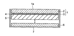
本発明の加熱体は、例えば図1に示すように、ヒータ基板2に発熱体3を設けたヒータ1と、断熱層4と、均熱板5とを備え、均熱板5はヒータ1のウエハ載置面1aと反対側の面に、断熱層4を介して固定されている。この均熱板5の熱伝導率はヒータ基板2よりも高く設定してあるため、発熱体3で発生した熱をヒータ1の全面に均一に拡げることができる。その結果、ヒータ1のウエハ載置面1aの均熱性が、均熱板5がない場合に比較して大幅に向上する。
For example, as shown in FIG. 1, the heating body of the present invention includes a heater 1 in which a heating element 3 is provided on a heater substrate 2, a
しかしながら、断熱層4なしに均熱板5をヒータ1に直接取り付けた場合には、発熱体3によりヒータ1を昇温する際に、均熱板5の熱容量の影響によって昇温速度が低下することが避けられない。それに対して、ヒータ1と均熱板5の間に断熱層4を取り付けることによって、発熱体3で発生した熱のうち均熱板5に奪われる量が低減されるので、その分だけヒータ1の昇温速度を速めることができるのである。
However, when the
本発明に使用するヒータ1は、図1に示すように、発熱体3を備えたヒータ基板2からなり、その片方の面(上記断熱層4及び均熱板5が固定されている面と反対側の面)がウエハ載置面1aとなっている。ヒータ基板の材質としては、特に制約はなく、従来から使用されている金属製のヒータ基板やセラミックス製のヒータ基板を使用することができる。また、金属とセラミックスの複合体、例えばCu−W、Si−SiC、Al−SiCなども好適に使用することができる。
As shown in FIG. 1, the heater 1 used in the present invention is composed of a heater substrate 2 provided with a heating element 3, and one surface thereof (opposite to the surface on which the
特に近年では、ウエハを載置する加熱体に対して、パーティクルの発生を抑制することが要求されている。このため、上記したヒータ基板の材料の中でも、セラミックスがパーティクルの発生が少ないため好ましい。好ましいセラミックスとしては、炭化ケイ素、窒化ケイ素、窒化アルミニウム、アルミナ、ムライト、これらの複合体をあげることができる。特に炭化ケイ素や窒化アルミニウムは熱伝導率が高く、ウエハ載置面の温度分布が均一になりやすいため好ましい。尚、熱伝導率が100W/mK以上の材質であれば、均熱性に優れたヒータを得ることができる。 Particularly in recent years, it has been required to suppress the generation of particles for a heating body on which a wafer is placed. For this reason, among the materials for the heater substrate described above, ceramics is preferable because it generates less particles. Preferred ceramics include silicon carbide, silicon nitride, aluminum nitride, alumina, mullite, and composites thereof. In particular, silicon carbide and aluminum nitride are preferable because of high thermal conductivity and a uniform temperature distribution on the wafer mounting surface. If the material has a thermal conductivity of 100 W / mK or more, a heater with excellent heat uniformity can be obtained.
ヒータに具備される発熱体は、従来から使用されている材質、例えば、WやMo、ステンレス、ニクロムなどでよく、ヒータ基板中に埋設してもよいし、ヒータ基板のウエハ載置面と反対側の面に設置してもよい。これらの発熱体は、印刷などの手法により基板上に所定のパターンで形成するか、エッチングにより所定のパターンに形成したコイルや金属箔を用いることができる。発熱体がコイルや金属箔の場合、ネジ止め等の機械的手法で基板に固定することも可能である。また、発熱体を基板に埋設する方法としては、例えば、2枚の基板の間に上記コイルや金属箔を挟み込んで重ね合わせるか、表面に印刷などの手法で発熱体を形成した基板を他の基板と重ね合わせることで埋設することができる。 The heating element provided in the heater may be a conventionally used material, for example, W, Mo, stainless steel, nichrome, etc., and may be embedded in the heater substrate or opposite the wafer mounting surface of the heater substrate. You may install in the side surface. These heating elements can be formed on the substrate in a predetermined pattern by a technique such as printing, or a coil or metal foil formed in a predetermined pattern by etching. When the heating element is a coil or a metal foil, it can be fixed to the substrate by a mechanical method such as screwing. In addition, as a method of embedding the heating element in the substrate, for example, the above-described coil or metal foil is sandwiched between two substrates and stacked, or a substrate on which the heating element is formed by printing or the like is used for another substrate. It can be embedded by overlapping with the substrate.
上記ヒータ基板が導体の場合には、発熱体を絶縁体で挟み込むことで絶縁を確保した上で、ヒータ基板に取り付ける。発熱体を挟み込む絶縁体としては、耐熱性を有する絶縁体であれば特に制約はなく、例えば、マイカ、シリコン樹脂、エポキシ樹脂、フェノール樹脂などを用いることができる。また、絶縁性の樹脂で発熱体を挟み込む場合、樹脂の熱伝導性を高めて、発熱体で発生した熱をスムースにヒータに伝えるために、樹脂中にフィラーを分散させることができる。かかるフィラーの材質としては、樹脂との反応性がなければ特に制約はなく、例えば、窒化ホウ素、窒化アルミニウム、アルミナ、シリカなどの物質をあげることができる。 When the heater substrate is a conductor, it is attached to the heater substrate after ensuring insulation by sandwiching the heating element with an insulator. The insulator that sandwiches the heating element is not particularly limited as long as it is a heat-resistant insulator. For example, mica, silicon resin, epoxy resin, phenol resin, or the like can be used. In addition, when the heating element is sandwiched between insulating resins, the filler can be dispersed in the resin in order to increase the thermal conductivity of the resin and smoothly transmit the heat generated in the heating element to the heater. The filler material is not particularly limited as long as it does not react with the resin, and examples thereof include boron nitride, aluminum nitride, alumina, and silica.
ヒータと均熱板の間に取り付ける断熱層の材質としては、上記ヒータ基板よりも熱伝導率が低く、耐熱性に優れたものであれば特に制約はない。具体的には、マイカ、シリコン樹脂、エポキシ樹脂、フェノール樹脂、ポリイミド樹脂などをあげることができる。また、発泡金属などの変形能を有するものも使用可能である。これらの断熱層は、ヒータで発生した熱のうち、均熱板に伝えられる熱量を減少させることによって、ヒータの昇温速度をより一層向上させる作用を有している。 The material of the heat insulating layer attached between the heater and the soaking plate is not particularly limited as long as it has a lower thermal conductivity than the heater substrate and is excellent in heat resistance. Specifically, mica, silicon resin, epoxy resin, phenol resin, polyimide resin, and the like can be given. Moreover, what has deformability, such as a foam metal, can also be used. These heat insulation layers have the effect of further increasing the temperature increase rate of the heater by reducing the amount of heat transmitted to the soaking plate among the heat generated by the heater.
断熱層を介してヒータに取り付ける均熱板は、ヒータよりも熱伝導率の高いことが必要である。かかる均熱板の材質としては、例えば、銅やアルミニウムなどの金属又はその合金、セラミックス、あるいはセラミックスと金属の複合体などがあげられる。これらの中では、熱伝導率の高い銅又はその合金が特に好適である。これら熱伝導率が高い材質の均熱板を設置することによって、ヒータのウエハ載置面の温度分布をより均一にすることができる。 The soaking plate attached to the heater via the heat insulating layer needs to have higher thermal conductivity than the heater. Examples of the material of the soaking plate include metals such as copper and aluminum or alloys thereof, ceramics, and composites of ceramics and metals. Among these, copper having a high thermal conductivity or an alloy thereof is particularly suitable. By installing these soaking plates made of a material having a high thermal conductivity, the temperature distribution on the wafer mounting surface of the heater can be made more uniform.
即ち、ヒータを昇温させる際には、断熱層が介在するため均熱板への熱の伝わりは悪く、ヒータの昇温速度に追従することができないため、均熱板の影響は比較的小さい。しかしながら、断熱層を介して均熱板に伝わった熱は、たとえ少量であっても均熱板内を均一に加熱するため、断熱層を介して存在するヒータのウエハ載置面の温度分布をより均熱となる方向に改善することができる。勿論、ウエハ処理の過渡的状態においても、ヒータよりも温度が低く且つ均一な温度分布を有する均熱板がヒータの裏面側に存在することで、例えばヒータの部分的に温度の高いホットスポットの発生などを抑えることができるため、ウエハ載置面はより均一な温度分布となる。 That is, when the temperature of the heater is raised, the heat transfer to the soaking plate is poor because of the presence of the heat insulation layer, and the heating rate of the heater cannot be followed, so the influence of the soaking plate is relatively small. . However, even if a small amount of heat is transferred to the heat equalizing plate through the heat insulating layer, the temperature inside the heat equalizing plate is heated uniformly. Therefore, the temperature distribution on the wafer mounting surface of the heater existing through the heat insulating layer is reduced. It can improve in the direction which becomes more uniform. Of course, even in a transient state of wafer processing, a heat equalizing plate having a temperature distribution lower than that of the heater and having a uniform temperature distribution is present on the back surface side of the heater. Since generation | occurrence | production etc. can be suppressed, a wafer mounting surface becomes more uniform temperature distribution.
また、均熱板の熱容量をヒータ基板よりも大きくすることで、均熱板自身の温度分布が均一になりやすく、従って一層均一なウエハ載置面の温度分布を実現することができる。更には、熱容量がヒータ基板よりも大きい均熱板を用いることによって、ヒータ基板の熱容量が相対的に小さくなるため、昇温速度を速くすることができ、高速昇温と高均熱性を同時に達成することができる。 Further, by making the heat capacity of the heat equalizing plate larger than that of the heater substrate, the temperature distribution of the heat equalizing plate itself is likely to be uniform, so that a more uniform temperature distribution on the wafer mounting surface can be realized. Furthermore, by using a heat equalizing plate with a larger heat capacity than the heater substrate, the heat capacity of the heater substrate becomes relatively small, so that the rate of temperature rise can be increased, achieving high temperature rise and high temperature uniformity at the same time. can do.
ヒータへの断熱層及び均熱板の取り付け方法に関しては、特に制約はなく、ロウ付けや接合などの手法のほか、ネジ止めなどの機械的な手法をとることができる。均熱板、断熱層、ヒータ基板の各材質の熱膨張係数にもよるが、これらの材質は一般的に熱膨張係数が異なるため、ネジ止めなどの機械的な手法で固定する構造が好ましい。機械的な固定方法としては、例えば、ヒータ基板のウエハ載置面とは反対側の面に雌ネジ穴を形成すると共に、均熱板にネジ径よりも大きな貫通孔を形成し、ボルトを挿通して固定する方法がある。この場合、均熱板のネジ穴の直径を大きくすることで、均熱板とヒータと断熱層の温度による膨張差や、熱膨張係数による寸法差を吸収することができる。 There are no particular restrictions on the method of attaching the heat insulating layer and the heat equalizing plate to the heater, and mechanical methods such as screwing can be used in addition to methods such as brazing and joining. Although depending on the thermal expansion coefficient of each material of the heat equalizing plate, the heat insulating layer, and the heater substrate, since these materials generally have different thermal expansion coefficients, a structure that is fixed by a mechanical method such as screwing is preferable. As a mechanical fixing method, for example, a female screw hole is formed on the surface of the heater substrate opposite to the wafer mounting surface, a through hole larger than the screw diameter is formed in the heat equalizing plate, and a bolt is inserted. There is a way to fix it. In this case, by increasing the diameter of the screw hole of the heat equalizing plate, it is possible to absorb the expansion difference due to the temperatures of the heat equalizing plate, the heater, and the heat insulating layer and the dimensional difference due to the thermal expansion coefficient.
本発明の加熱体においては、例えば図1に示すように、均熱板5のヒータ1と反対側の下方に、冷却モジュール6を配置することができる。冷却モジュールは、均熱板やヒータを冷却する必要が生じた際に、ウエハ載置面の反対側から均熱板の裏面当接して、その熱を奪うことにより、ヒータや均熱板を急速に冷却することができる。また、ヒータの加熱時には均熱板から離間させることで、効率よく昇温することができるため、冷却モジュールは可動式であることが好ましい。冷却モジュールを可動式にする手法としては、エアシリンダーなどの昇降手段を用いる。このように冷却モジュールを設置することで、ヒータの冷却速度を大幅に向上させ、スループットを向上させることができる。
In the heating body of the present invention, for example, as shown in FIG. 1, a cooling module 6 can be disposed below the soaking
また、ヒータの冷却速度を優先する場合には、冷却モジュールを加熱体の均熱板に固定してもよい。この構造の場合、ヒータと冷却モジュールが均熱板などを介して固定されているため、冷却モジュールが可動式の場合に比較して、冷却速度を速くすることができる。冷却モジュールの固定方法としては、上記した均熱板とヒータの固定の場合と同様に、ネジ止めなどの機械的な手法で固定することができる。また、ネジ止めでヒータや均熱板、冷却モジュールを固定する場合、それぞれネジの個数を3個以上、更には6個以上とすることで、各部の密着性が高まり、ヒータの冷却能力がより向上するため好ましい。 Further, when priority is given to the cooling rate of the heater, the cooling module may be fixed to the soaking plate of the heating body. In the case of this structure, since the heater and the cooling module are fixed via a soaking plate or the like, the cooling rate can be increased compared to the case where the cooling module is movable. As a method for fixing the cooling module, it can be fixed by a mechanical method such as screwing as in the case of fixing the soaking plate and the heater. In addition, when fixing the heater, heat equalizing plate, and cooling module with screws, the number of screws is set to 3 or more, and further 6 or more, so that the adhesion of each part is increased and the cooling capacity of the heater is further improved. It is preferable because it improves.
冷却モジュールの材質としては、特に制約はないが、アルミニウムや銅及びその合金は熱伝導率が比較的高いため、特に好ましく用いられる。また、ステンレス、マグネシウム合金、ニッケル、その他の金属材料を使用することもできる。更に、冷却モジュールに耐酸化性を付与するために、表面にニッケル、金、銀などの耐酸化性を有する金属膜をメッキや溶射などの手法を用いて形成することができる。これらの中では、アルミニウムにニッケルメッキを施したものや、銅にニッケルメッキを施したものが耐酸化性にも優れ、また熱伝導率も高く、価格的にも比較的安価であるため、特に好ましい。 The material of the cooling module is not particularly limited, but aluminum, copper and alloys thereof are particularly preferably used because of their relatively high thermal conductivity. Also, stainless steel, magnesium alloy, nickel, and other metal materials can be used. Furthermore, in order to impart oxidation resistance to the cooling module, a metal film having oxidation resistance such as nickel, gold, or silver can be formed on the surface using a technique such as plating or thermal spraying. Among these, aluminum plated nickel and copper plated nickel are excellent in oxidation resistance, have high thermal conductivity, and are relatively inexpensive. preferable.
また、冷却モジュールの材質としてセラミックスを使用することもできる。この場合のセラミックスとしては、特に制約はないが、窒化アルミニウムや炭化ケイ素は熱伝導率が比較的高く、素早く熱を奪うことができるため好ましい。また、窒化ケイ素や酸窒化アルミニウムは、機械的強度が高く、耐久性に優れているため好ましい。更に、アルミナ、コージェライト、ステアタイトなどの酸化物セラミックスは、比較的安価であるため好ましい。このように冷却モジュールの材質は、種々選択できるため、用途に応じて材質を選択すればよい。 Ceramics can also be used as the material for the cooling module. The ceramic in this case is not particularly limited, but aluminum nitride and silicon carbide are preferable because they have a relatively high thermal conductivity and can quickly take heat away. Silicon nitride and aluminum oxynitride are preferable because of high mechanical strength and excellent durability. Furthermore, oxide ceramics such as alumina, cordierite, and steatite are preferable because they are relatively inexpensive. Thus, since the material of a cooling module can be selected variously, what is necessary is just to select a material according to a use.
上記冷却モジュールの内部には、冷媒を流すことも可能である。冷媒を流すことによって、加熱体から冷却モジュールに伝達された熱を素早く取り除くことができるため、更に加熱体の冷却速度を向上させることができる。冷却モジュール内に流す冷媒としては、水のほか、フロリナートなどの液体、窒素や大気などの気体などが選択でき、特に制約はないが、比熱の大きさ、価格などを考慮すると水が最も好ましい。 It is also possible to flow a coolant through the cooling module. By flowing the refrigerant, the heat transferred from the heating body to the cooling module can be quickly removed, so that the cooling rate of the heating body can be further improved. As the refrigerant flowing in the cooling module, water, liquid such as fluorinate, gas such as nitrogen and air can be selected, and there is no particular limitation, but water is most preferable in consideration of the specific heat, price, and the like.
尚、冷却モジュールを加熱体の均熱板に固定する場合には、冷却モジュールに冷媒を流さずに昇温することも可能である。この場合、冷却モジュール内に冷媒が流れていないため、発熱体で発生した熱が冷媒に奪われて系外に逃げることがなく、より効率的な昇温が可能となる。しかし、この場合であっても、冷却時には冷却モジュールに冷媒を流すことで、効率的な冷却が可能になる。 In addition, when fixing a cooling module to the soaking | uniform-heating board of a heating body, it is also possible to heat up, without flowing a refrigerant | coolant to a cooling module. In this case, since the refrigerant does not flow in the cooling module, the heat generated by the heating element is not lost to the refrigerant and escapes out of the system, and more efficient temperature rise is possible. However, even in this case, efficient cooling is possible by flowing the refrigerant through the cooling module during cooling.
冷媒用の流路を備えた冷却モジュールの好適な例としては、2枚のアルミニウム板を用意し、片方のアルミニウム板に冷媒を流す流路を機械加工等によって形成した後、このアルミニウム板に他方のアルミニウム板を張り合わせる。これらのアルミニウム板には、耐食性及び耐酸化性を向上させるために、全面にニッケルメッキを施すことが好ましい。また、水などの冷媒が漏れないように、例えばO-リング等を流路の周囲に挿入したうえで、ネジ止めや溶接によって2枚のアルミニウム板を張り合わせる。 As a preferable example of the cooling module having a flow path for the refrigerant, two aluminum plates are prepared, and a flow path for flowing the refrigerant to one aluminum plate is formed by machining or the like. Laminate aluminum plates. These aluminum plates are preferably nickel-plated over the entire surface in order to improve corrosion resistance and oxidation resistance. Further, in order to prevent a refrigerant such as water from leaking, for example, an O-ring or the like is inserted around the flow path, and then two aluminum plates are bonded together by screwing or welding.
あるいは、別の好適な形態としては、2枚の銅(無酸素銅)板を用意し、その片方の銅板に流路を機械加工等によって形成した後、この銅板と他方の銅板を、冷媒の出入口となるステンレス製のパイプと共に、同時にロウ付け接合することもできる。作製した冷却モジュールには、耐食性及び耐酸化性を向上させるために、ニッケルメッキを全面に施すことが好ましい。 Alternatively, as another preferred embodiment, two copper (oxygen-free copper) plates are prepared, and a flow path is formed in one copper plate by machining or the like. It can also be brazed and joined together with the stainless steel pipe serving as the doorway. The produced cooling module is preferably nickel-plated over the entire surface in order to improve corrosion resistance and oxidation resistance.
更に別の形態として、アルミニウム板もしくは銅板等の冷却板の片面に、冷媒を流すパイプを取り付けることで冷却モジュールとすることもできる。この場合、パイプの断面形状に近い形状のザグリ溝を冷却板に形成し、この溝内にパイプを密着させることで冷却効率を上げることができる。また、冷却パイプと冷却板の密着性を向上させるため、両者の間に介在層として熱伝導性の樹脂やセラミックス等を挿入してもよい。 Furthermore, as another form, it can also be set as a cooling module by attaching the pipe | tube which flows a refrigerant | coolant to the single side | surface of cooling plates, such as an aluminum plate or a copper plate. In this case, it is possible to increase the cooling efficiency by forming a counterbored groove having a shape close to the cross-sectional shape of the pipe in the cooling plate, and bringing the pipe into close contact with the groove. Moreover, in order to improve the adhesiveness of a cooling pipe and a cooling plate, you may insert thermally conductive resin, ceramics, etc. as an intervening layer between both.
上記した本発明の加熱体は、優れた均熱性と共に高い昇温速度が要求される半導体加熱用加熱体として特に好適である。従って、例えば図1に示すように、ヒータ1と、断熱層4と、均熱板5とを備えた本発明の加熱体は、必要に応じて冷却モジュール6と共に、容器7に収納されて、半導体ウエハ加熱用装置を構成することができる。
The heating body of the present invention described above is particularly suitable as a heating body for semiconductor heating that requires a high temperature rising rate as well as excellent soaking. Therefore, for example, as shown in FIG. 1, the heating body of the present invention including the heater 1, the
この半導体ウエハ加熱用装置を備えた半導体製造装置は、処理すべきウエハの温度分布をより均一にすることができる。そのため、例えば、CVDなどの成膜装置では、膜の厚みを均一にすることが可能となり、またコータデベロッパなどの装置では、配線などのパターンの精度を向上させることができる。更に、ウエハプローバなどの検査装置においても、温度分布に優れるために、良好なウエハの検査を実施することができる。また、昇温速度にも優れているため、スループットを向上させ、より短時間でのウエハ処理が可能となる。 The semiconductor manufacturing apparatus provided with this semiconductor wafer heating apparatus can make the temperature distribution of the wafer to be processed more uniform. Therefore, for example, in a film forming apparatus such as CVD, the thickness of the film can be made uniform, and in an apparatus such as a coater developer, the accuracy of patterns such as wiring can be improved. Further, in an inspection apparatus such as a wafer prober, since the temperature distribution is excellent, a good wafer inspection can be performed. Further, since the temperature rise rate is also excellent, throughput can be improved and wafer processing can be performed in a shorter time.
本発明による加熱体の具体例として、種々の材料からなるヒータ基板、断熱層及び均熱板を組み合わせた加熱体を構成し、その昇降温特性並びに均熱性を評価した。尚、ヒータ基板、断熱層及び均熱板として使用した材料の各物性値(熱伝導率、比熱、比重)は、下記表1に示すとおりである。 As a specific example of the heating body according to the present invention, a heating body comprising a heater substrate made of various materials, a heat insulating layer, and a soaking plate was constructed, and its temperature rising / falling characteristics and soaking properties were evaluated. In addition, each physical property value (thermal conductivity, specific heat, specific gravity) of the materials used as the heater substrate, the heat insulating layer, and the soaking plate is as shown in Table 1 below.

[実施例1]
下記表2に示す各材料からヒータ基板を作製し、直径を320mmとし且つ厚みを表2のとおり変化させた。これらのヒータ基板に、ステンレス箔(厚み0.05mm)をエッチングして所定のパターンとした発熱体を取り付け、ヒータとした。得られた各ヒータの発熱体側に、断熱層として厚み0.5mmのマイカと、下記表2に示す均熱板を順に取り付け、全体をボルト締めにより固定して加熱体を作製した。また、冷却モジュールとして、流路を形成した銅板をロウ付けにより張り合わせたものを用意した。
[Example 1]
A heater substrate was prepared from each material shown in Table 2 below, the diameter was set to 320 mm, and the thickness was changed as shown in Table 2. A heating element having a predetermined pattern formed by etching stainless steel foil (thickness 0.05 mm) was attached to these heater substrates to obtain heaters. Mica having a thickness of 0.5 mm and a soaking plate shown in the following Table 2 were sequentially attached to the heating element side of each heater obtained, and the whole was fixed by bolting to produce a heating element. In addition, a cooling module prepared by bonding copper plates on which flow paths were formed by brazing was prepared.
発熱体に給電して180℃に加熱し、加熱体が180℃に到達するまでの時間を測定すると共に、180℃到達から1分後にウエハを載置面に搭載し、更にその1分後のウエハの温度分布(180℃での均熱性)を17点のウエハ温度計(測温抵抗体)にて測定した。また、引き続いてウエハを脱着後、加熱体の裏面側に冷却モジュールを密着させることで180℃から150℃に冷却し、150℃に到達するまでの時間を測定すると共に、150℃到着から1分後にウエハを搭載し、更にその1分後のウエハの温度分布(150℃での均熱性)を上記と同様に測定した。得られた結果を下記表2に示す。 Power is supplied to the heating element and heated to 180 ° C., the time until the heating body reaches 180 ° C. is measured, and the wafer is mounted on the mounting surface 1 minute after reaching 180 ° C. The temperature distribution of the wafer (thermal uniformity at 180 ° C.) was measured with a 17-point wafer thermometer (resistance temperature detector). In addition, after the wafer is removed, the cooling module is brought into close contact with the back side of the heating body to cool it from 180 ° C. to 150 ° C., and the time until it reaches 150 ° C. is measured. A wafer was mounted later, and the temperature distribution (heat uniformity at 150 ° C.) of the wafer after 1 minute was measured in the same manner as described above. The obtained results are shown in Table 2 below.
上記表2の結果から、ヒータ基板が厚み10mmのCu板からなり且つ均熱板のない加熱体は、均熱性に優れているが、AlNヒータ基板と断熱層及び均熱板を組み合わせた本発明の加熱体に比較して、昇温速度及び降温速度が非常に遅いことが分る。また、AlNヒータ基板と断熱層からなり、均熱板のない加熱体に関しては、均熱板のあるものに比較して均熱性が悪いことが分る。更に、均熱板の熱容量がAlN基板より大きいものは、昇温速度が非常に速く、均熱性にも優れていることが分る。 From the results of Table 2 above, although the heater substrate is made of a Cu plate having a thickness of 10 mm and has no soaking plate, the heating body is excellent in soaking properties, but the present invention combines the AlN heater substrate, the heat insulating layer, and the soaking plate. It can be seen that the rate of temperature increase and the rate of temperature decrease is very slow as compared with the heating body. In addition, it can be seen that a heating element comprising an AlN heater substrate and a heat insulating layer and having no soaking plate has poor soaking properties compared to those having a soaking plate. Furthermore, it can be seen that when the heat capacity of the soaking plate is larger than that of the AlN substrate, the heating rate is very fast and the soaking property is excellent.
上記と同様に加熱体を作製したが、ヒータとしてAlNヒータ基板にステンレス箔の発熱体を埋設したものを使用した。得られた各加熱体について、上記と同様の試験を行い、均熱性と昇温速度及び降温速度を評価した。比較のために、断熱層を使用しない加熱体についても評価した。得られた結果を下記表3に示す。断熱層のない加熱体は、他のものに比べて昇温速度が極めて遅いことが分る。 A heating element was prepared in the same manner as described above, but a heater in which a stainless steel foil heating element was embedded in an AlN heater substrate was used. About each obtained heating body, the test similar to the above was done and soaking | uniform-heating property, the temperature increase rate, and the temperature-fall rate were evaluated. For comparison, a heating body that does not use a heat insulating layer was also evaluated. The obtained results are shown in Table 3 below. It can be seen that the heating element without the heat insulating layer has a very slow temperature increase rate compared to other heating elements.
[実施例2]
上記実施例1と同様に加熱体を作製したが、均熱板として下記表4に示すようにAlあるいはCu−Wを使用した。得られた各加熱体について、上記と同様の試験を行い、均熱性と昇温速度及び降温速度を評価した。得られた結果を下記表4に示す。下記表4の結果ら、均熱板の熱容量がヒータ基板の熱容量より大きい方が、昇温特性に優れていることが分る。
[Example 2]
Although the heating body was produced similarly to the said Example 1, as shown in following Table 4 as a soaking plate, Al or Cu-W was used. About each obtained heating body, the test similar to the above was done and soaking | uniform-heating property, the temperature increase rate, and the temperature-fall rate were evaluated. The results obtained are shown in Table 4 below. From the results of Table 4 below, it can be seen that the temperature rise characteristic is superior when the heat capacity of the soaking plate is larger than the heat capacity of the heater substrate.
[実施例3]
ヒータ基板として下記表5に示すSi−SiC又はAl−SiCを用い、直径を320mmとし且つ厚みを表5のとおり変化させた。これらのヒータ基板は導電性を有するため、ウエハ載置面の反対側に厚み0.1mmのポリイミドフィルムを貼り付け、更に発熱体として上記実施例1と同様にステンレス箔を、及び断熱層として厚さ0.2mmのポリイミドフィルムを、更に均熱板として表5に示す厚みのCu板を使用して、それぞれ加熱体を作製した。
[Example 3]
As a heater substrate, Si—SiC or Al—SiC shown in Table 5 below was used, the diameter was changed to 320 mm, and the thickness was changed as shown in Table 5. Since these heater substrates have conductivity, a polyimide film having a thickness of 0.1 mm is pasted on the opposite side of the wafer mounting surface, and a stainless steel foil is used as a heating element in the same manner as in the first embodiment, and a heat insulating layer. Heating bodies were prepared using 0.2 mm thick polyimide films and Cu plates with the thicknesses shown in Table 5 as the soaking plates.
得られた各加熱体について、上記と同様の試験を行い、均熱性と昇温速度及び降温速度を評価した。得られた結果を下記表5に示す。下記表5の結果ら分るように、均熱板の熱容量がヒータ基板の熱容量より大きい方が昇温特性に優れている。 About each obtained heating body, the test similar to the above was done and soaking | uniform-heating property, the temperature increase rate, and the temperature-fall rate were evaluated. The obtained results are shown in Table 5 below. As can be seen from the results in Table 5 below, the temperature rise characteristic is superior when the heat capacity of the soaking plate is larger than the heat capacity of the heater substrate.
1 ヒータ
1a ウエハ載置面
2 ヒータ基板
3 発熱体
4 断熱層
5 均熱板
6 冷却モジュール
7 容器
DESCRIPTION OF SYMBOLS 1
Claims (7)
Priority Applications (1)
| Application Number | Priority Date | Filing Date | Title |
|---|---|---|---|
| JP2006302555A JP5157131B2 (en) | 2006-11-08 | 2006-11-08 | Heating body and semiconductor manufacturing apparatus equipped with the same |
Applications Claiming Priority (1)
| Application Number | Priority Date | Filing Date | Title |
|---|---|---|---|
| JP2006302555A JP5157131B2 (en) | 2006-11-08 | 2006-11-08 | Heating body and semiconductor manufacturing apparatus equipped with the same |
Publications (3)
| Publication Number | Publication Date |
|---|---|
| JP2008118080A JP2008118080A (en) | 2008-05-22 |
| JP2008118080A5 JP2008118080A5 (en) | 2009-12-17 |
| JP5157131B2 true JP5157131B2 (en) | 2013-03-06 |
Family
ID=39503764
Family Applications (1)
| Application Number | Title | Priority Date | Filing Date |
|---|---|---|---|
| JP2006302555A Active JP5157131B2 (en) | 2006-11-08 | 2006-11-08 | Heating body and semiconductor manufacturing apparatus equipped with the same |
Country Status (1)
| Country | Link |
|---|---|
| JP (1) | JP5157131B2 (en) |
Families Citing this family (5)
| Publication number | Priority date | Publication date | Assignee | Title |
|---|---|---|---|---|
| JP5447123B2 (en) * | 2009-05-28 | 2014-03-19 | 住友電気工業株式会社 | Heater unit and apparatus provided with the same |
| JP5416570B2 (en) * | 2009-12-15 | 2014-02-12 | 住友電気工業株式会社 | Heating / cooling device and apparatus equipped with the same |
| CN104752301B (en) * | 2013-12-31 | 2018-05-25 | 北京北方华创微电子装备有限公司 | A kind of electrostatic chuck and chamber |
| NL2015429B1 (en) * | 2015-09-11 | 2017-03-29 | Walker Holdings B V | Portable stove for solid fuels. |
| CN117286474A (en) * | 2022-12-28 | 2023-12-26 | 无锡至辰科技有限公司 | High-temperature metal shell wafer heater and processing method thereof |
Family Cites Families (1)
| Publication number | Priority date | Publication date | Assignee | Title |
|---|---|---|---|---|
| JP2002025912A (en) * | 2000-07-04 | 2002-01-25 | Sumitomo Electric Ind Ltd | Susceptor for semiconductor manufacturing device and semiconductor manufacturing device using the same |
-
2006
- 2006-11-08 JP JP2006302555A patent/JP5157131B2/en active Active
Also Published As
| Publication number | Publication date |
|---|---|
| JP2008118080A (en) | 2008-05-22 |
Similar Documents
| Publication | Publication Date | Title |
|---|---|---|
| JP4497103B2 (en) | Wafer holder, heater unit on which it is mounted, and wafer prober | |
| JP5416570B2 (en) | Heating / cooling device and apparatus equipped with the same | |
| JP4950688B2 (en) | Mounting device | |
| US7425838B2 (en) | Body for keeping a wafer and wafer prober using the same | |
| JP5157131B2 (en) | Heating body and semiconductor manufacturing apparatus equipped with the same | |
| JP2007035899A (en) | Wafer holding body for wafer prober, and wafer prober mounting the same | |
| JP4893543B2 (en) | Wafer holder and semiconductor manufacturing apparatus equipped with the same | |
| JP5381878B2 (en) | Wafer heating heater unit and semiconductor manufacturing apparatus equipped with the same | |
| JP4063291B2 (en) | Wafer holder for wafer prober and wafer prober equipped with the same | |
| JP4433478B2 (en) | Heating device and wafer prober equipped with the same | |
| JP4525571B2 (en) | Wafer holder, heater unit on which it is mounted, and wafer prober | |
| JP4462140B2 (en) | Wafer prober chuck top, wafer holder, and wafer prober including the same | |
| JP6060889B2 (en) | Heater unit for wafer heating | |
| JP2007042958A (en) | Wafer holder for wafer prober and wafer prober mounted with same | |
| WO2015104954A1 (en) | Electronic circuit device | |
| JP2007115736A (en) | Wafer heating hot plate | |
| JP5605265B2 (en) | Heater unit for semiconductor manufacturing equipment | |
| JP2013004810A (en) | Heater for heating wafer | |
| JP2013123053A (en) | Device for heating and cooling, and apparatus with the same | |
| JP2007227442A (en) | Wafer holding body and wafer prober mounted with the same | |
| JP2005340043A (en) | Heating device | |
| JP5381879B2 (en) | Wafer heating heater unit and semiconductor manufacturing apparatus equipped with the same | |
| US20070182433A1 (en) | Wafer holder, and wafer prober and semiconductor manufacturing apparatus provided therewith | |
| JP2011081932A (en) | Heater and device mounting the same | |
| JP4627839B2 (en) | Module and its manufacturing method |
Legal Events
| Date | Code | Title | Description |
|---|---|---|---|
| A521 | Request for written amendment filed |
Free format text: JAPANESE INTERMEDIATE CODE: A821 Effective date: 20080128 |
|
| A521 | Request for written amendment filed |
Free format text: JAPANESE INTERMEDIATE CODE: A821 Effective date: 20090612 |
|
| A711 | Notification of change in applicant |
Free format text: JAPANESE INTERMEDIATE CODE: A712 Effective date: 20090612 |
|
| A521 | Request for written amendment filed |
Free format text: JAPANESE INTERMEDIATE CODE: A523 Effective date: 20091104 |
|
| A621 | Written request for application examination |
Free format text: JAPANESE INTERMEDIATE CODE: A621 Effective date: 20091104 |
|
| A977 | Report on retrieval |
Free format text: JAPANESE INTERMEDIATE CODE: A971007 Effective date: 20120222 |
|
| A131 | Notification of reasons for refusal |
Free format text: JAPANESE INTERMEDIATE CODE: A131 Effective date: 20120313 |
|
| A521 | Request for written amendment filed |
Free format text: JAPANESE INTERMEDIATE CODE: A523 Effective date: 20120511 |
|
| TRDD | Decision of grant or rejection written | ||
| A01 | Written decision to grant a patent or to grant a registration (utility model) |
Free format text: JAPANESE INTERMEDIATE CODE: A01 Effective date: 20121113 |
|
| A61 | First payment of annual fees (during grant procedure) |
Free format text: JAPANESE INTERMEDIATE CODE: A61 Effective date: 20121126 |
|
| R150 | Certificate of patent or registration of utility model |
Ref document number: 5157131 Country of ref document: JP Free format text: JAPANESE INTERMEDIATE CODE: R150 Free format text: JAPANESE INTERMEDIATE CODE: R150 |
|
| FPAY | Renewal fee payment (event date is renewal date of database) |
Free format text: PAYMENT UNTIL: 20151221 Year of fee payment: 3 |
|
| R250 | Receipt of annual fees |
Free format text: JAPANESE INTERMEDIATE CODE: R250 |
|
| R250 | Receipt of annual fees |
Free format text: JAPANESE INTERMEDIATE CODE: R250 |
|
| R250 | Receipt of annual fees |
Free format text: JAPANESE INTERMEDIATE CODE: R250 |
|
| R250 | Receipt of annual fees |
Free format text: JAPANESE INTERMEDIATE CODE: R250 |
|
| R250 | Receipt of annual fees |
Free format text: JAPANESE INTERMEDIATE CODE: R250 |
|
| R250 | Receipt of annual fees |
Free format text: JAPANESE INTERMEDIATE CODE: R250 |
|
| R250 | Receipt of annual fees |
Free format text: JAPANESE INTERMEDIATE CODE: R250 |
|
| R250 | Receipt of annual fees |
Free format text: JAPANESE INTERMEDIATE CODE: R250 |
|
| R250 | Receipt of annual fees |
Free format text: JAPANESE INTERMEDIATE CODE: R250 |