JP5156889B2 - Firewall structure - Google Patents
Firewall structure Download PDFInfo
- Publication number
- JP5156889B2 JP5156889B2 JP2008558340A JP2008558340A JP5156889B2 JP 5156889 B2 JP5156889 B2 JP 5156889B2 JP 2008558340 A JP2008558340 A JP 2008558340A JP 2008558340 A JP2008558340 A JP 2008558340A JP 5156889 B2 JP5156889 B2 JP 5156889B2
- Authority
- JP
- Japan
- Prior art keywords
- track
- metal plate
- side wall
- pair
- sliding extension
- Prior art date
- Legal status (The legal status is an assumption and is not a legal conclusion. Google has not performed a legal analysis and makes no representation as to the accuracy of the status listed.)
- Expired - Fee Related
Links
- 229910052751 metal Inorganic materials 0.000 claims description 85
- 239000002184 metal Substances 0.000 claims description 84
- 239000000463 material Substances 0.000 claims description 31
- 230000007246 mechanism Effects 0.000 claims description 11
- 230000008859 change Effects 0.000 claims description 10
- 238000006116 polymerization reaction Methods 0.000 claims 1
- 230000008602 contraction Effects 0.000 description 8
- 229910000831 Steel Inorganic materials 0.000 description 7
- 238000010276 construction Methods 0.000 description 7
- 238000010438 heat treatment Methods 0.000 description 7
- 238000000034 method Methods 0.000 description 7
- 239000012778 molding material Substances 0.000 description 7
- 239000010959 steel Substances 0.000 description 7
- 230000036961 partial effect Effects 0.000 description 5
- 239000000779 smoke Substances 0.000 description 5
- 230000000694 effects Effects 0.000 description 4
- 238000009434 installation Methods 0.000 description 4
- 238000005259 measurement Methods 0.000 description 4
- 238000010079 rubber tapping Methods 0.000 description 4
- 125000006850 spacer group Chemical group 0.000 description 4
- 229910052602 gypsum Inorganic materials 0.000 description 3
- 239000010440 gypsum Substances 0.000 description 3
- 238000010168 coupling process Methods 0.000 description 2
- 230000000670 limiting effect Effects 0.000 description 2
- 238000004519 manufacturing process Methods 0.000 description 2
- 238000005192 partition Methods 0.000 description 2
- 230000003044 adaptive effect Effects 0.000 description 1
- 238000005452 bending Methods 0.000 description 1
- 230000015572 biosynthetic process Effects 0.000 description 1
- 238000009435 building construction Methods 0.000 description 1
- 230000000295 complement effect Effects 0.000 description 1
- 230000001010 compromised effect Effects 0.000 description 1
- 238000001816 cooling Methods 0.000 description 1
- 230000008878 coupling Effects 0.000 description 1
- 238000005859 coupling reaction Methods 0.000 description 1
- 230000002950 deficient Effects 0.000 description 1
- 238000006073 displacement reaction Methods 0.000 description 1
- 238000005516 engineering process Methods 0.000 description 1
- 230000009970 fire resistant effect Effects 0.000 description 1
- 238000012986 modification Methods 0.000 description 1
- 230000004048 modification Effects 0.000 description 1
- 229910052755 nonmetal Inorganic materials 0.000 description 1
- 238000004080 punching Methods 0.000 description 1
- 230000002829 reductive effect Effects 0.000 description 1
- 230000004044 response Effects 0.000 description 1
- 230000002441 reversible effect Effects 0.000 description 1
- 238000007789 sealing Methods 0.000 description 1
- 238000000926 separation method Methods 0.000 description 1
- 239000000758 substrate Substances 0.000 description 1
- 239000002341 toxic gas Substances 0.000 description 1
- 239000011800 void material Substances 0.000 description 1
- XLYOFNOQVPJJNP-UHFFFAOYSA-N water Substances O XLYOFNOQVPJJNP-UHFFFAOYSA-N 0.000 description 1
Images


Classifications
-
- E—FIXED CONSTRUCTIONS
- E04—BUILDING
- E04B—GENERAL BUILDING CONSTRUCTIONS; WALLS, e.g. PARTITIONS; ROOFS; FLOORS; CEILINGS; INSULATION OR OTHER PROTECTION OF BUILDINGS
- E04B1/00—Constructions in general; Structures which are not restricted either to walls, e.g. partitions, or floors or ceilings or roofs
- E04B1/62—Insulation or other protection; Elements or use of specified material therefor
- E04B1/92—Protection against other undesired influences or dangers
- E04B1/94—Protection against other undesired influences or dangers against fire
-
- E—FIXED CONSTRUCTIONS
- E04—BUILDING
- E04B—GENERAL BUILDING CONSTRUCTIONS; WALLS, e.g. PARTITIONS; ROOFS; FLOORS; CEILINGS; INSULATION OR OTHER PROTECTION OF BUILDINGS
- E04B2/00—Walls, e.g. partitions, for buildings; Wall construction with regard to insulation; Connections specially adapted to walls
- E04B2/74—Removable non-load-bearing partitions; Partitions with a free upper edge
- E04B2/7407—Removable non-load-bearing partitions; Partitions with a free upper edge assembled using frames with infill panels or coverings only; made-up of panels and a support structure incorporating posts
- E04B2/7409—Removable non-load-bearing partitions; Partitions with a free upper edge assembled using frames with infill panels or coverings only; made-up of panels and a support structure incorporating posts special measures for sound or thermal insulation, including fire protection
- E04B2/7411—Details for fire protection
-
- E—FIXED CONSTRUCTIONS
- E04—BUILDING
- E04B—GENERAL BUILDING CONSTRUCTIONS; WALLS, e.g. PARTITIONS; ROOFS; FLOORS; CEILINGS; INSULATION OR OTHER PROTECTION OF BUILDINGS
- E04B2/00—Walls, e.g. partitions, for buildings; Wall construction with regard to insulation; Connections specially adapted to walls
- E04B2/72—Non-load-bearing walls of elements of relatively thin form with respect to the thickness of the wall
-
- E—FIXED CONSTRUCTIONS
- E04—BUILDING
- E04B—GENERAL BUILDING CONSTRUCTIONS; WALLS, e.g. PARTITIONS; ROOFS; FLOORS; CEILINGS; INSULATION OR OTHER PROTECTION OF BUILDINGS
- E04B2/00—Walls, e.g. partitions, for buildings; Wall construction with regard to insulation; Connections specially adapted to walls
- E04B2/74—Removable non-load-bearing partitions; Partitions with a free upper edge
- E04B2/7407—Removable non-load-bearing partitions; Partitions with a free upper edge assembled using frames with infill panels or coverings only; made-up of panels and a support structure incorporating posts
- E04B2/7453—Removable non-load-bearing partitions; Partitions with a free upper edge assembled using frames with infill panels or coverings only; made-up of panels and a support structure incorporating posts with panels and support posts, extending from floor to ceiling
- E04B2/7457—Removable non-load-bearing partitions; Partitions with a free upper edge assembled using frames with infill panels or coverings only; made-up of panels and a support structure incorporating posts with panels and support posts, extending from floor to ceiling with wallboards attached to the outer faces of the posts, parallel to the partition
-
- E—FIXED CONSTRUCTIONS
- E04—BUILDING
- E04B—GENERAL BUILDING CONSTRUCTIONS; WALLS, e.g. PARTITIONS; ROOFS; FLOORS; CEILINGS; INSULATION OR OTHER PROTECTION OF BUILDINGS
- E04B2/00—Walls, e.g. partitions, for buildings; Wall construction with regard to insulation; Connections specially adapted to walls
- E04B2/74—Removable non-load-bearing partitions; Partitions with a free upper edge
- E04B2/76—Removable non-load-bearing partitions; Partitions with a free upper edge with framework or posts of metal
- E04B2/766—T-connections
- E04B2/767—Connections between wall studs and upper or lower locating rails
-
- E—FIXED CONSTRUCTIONS
- E04—BUILDING
- E04B—GENERAL BUILDING CONSTRUCTIONS; WALLS, e.g. PARTITIONS; ROOFS; FLOORS; CEILINGS; INSULATION OR OTHER PROTECTION OF BUILDINGS
- E04B2/00—Walls, e.g. partitions, for buildings; Wall construction with regard to insulation; Connections specially adapted to walls
- E04B2/74—Removable non-load-bearing partitions; Partitions with a free upper edge
- E04B2/76—Removable non-load-bearing partitions; Partitions with a free upper edge with framework or posts of metal
- E04B2/78—Removable non-load-bearing partitions; Partitions with a free upper edge with framework or posts of metal characterised by special cross-section of the frame members as far as important for securing wall panels to a framework with or without the help of cover-strips
- E04B2/7854—Removable non-load-bearing partitions; Partitions with a free upper edge with framework or posts of metal characterised by special cross-section of the frame members as far as important for securing wall panels to a framework with or without the help of cover-strips of open profile
- E04B2/789—Removable non-load-bearing partitions; Partitions with a free upper edge with framework or posts of metal characterised by special cross-section of the frame members as far as important for securing wall panels to a framework with or without the help of cover-strips of open profile of substantially U- or C- section
-
- E—FIXED CONSTRUCTIONS
- E04—BUILDING
- E04C—STRUCTURAL ELEMENTS; BUILDING MATERIALS
- E04C2/00—Building elements of relatively thin form for the construction of parts of buildings, e.g. sheet materials, slabs, or panels
- E04C2/30—Building elements of relatively thin form for the construction of parts of buildings, e.g. sheet materials, slabs, or panels characterised by the shape or structure
- E04C2/34—Building elements of relatively thin form for the construction of parts of buildings, e.g. sheet materials, slabs, or panels characterised by the shape or structure composed of two or more spaced sheet-like parts
-
- E—FIXED CONSTRUCTIONS
- E04—BUILDING
- E04C—STRUCTURAL ELEMENTS; BUILDING MATERIALS
- E04C3/00—Structural elongated elements designed for load-supporting
- E04C3/02—Joists; Girders, trusses, or trusslike structures, e.g. prefabricated; Lintels; Transoms; Braces
-
- E—FIXED CONSTRUCTIONS
- E04—BUILDING
- E04B—GENERAL BUILDING CONSTRUCTIONS; WALLS, e.g. PARTITIONS; ROOFS; FLOORS; CEILINGS; INSULATION OR OTHER PROTECTION OF BUILDINGS
- E04B2/00—Walls, e.g. partitions, for buildings; Wall construction with regard to insulation; Connections specially adapted to walls
- E04B2/74—Removable non-load-bearing partitions; Partitions with a free upper edge
- E04B2/7407—Removable non-load-bearing partitions; Partitions with a free upper edge assembled using frames with infill panels or coverings only; made-up of panels and a support structure incorporating posts
- E04B2/7453—Removable non-load-bearing partitions; Partitions with a free upper edge assembled using frames with infill panels or coverings only; made-up of panels and a support structure incorporating posts with panels and support posts, extending from floor to ceiling
- E04B2/7459—Removable non-load-bearing partitions; Partitions with a free upper edge assembled using frames with infill panels or coverings only; made-up of panels and a support structure incorporating posts with panels and support posts, extending from floor to ceiling with telescoping posts to compensate for floor or ceiling irregularities
Landscapes
- Engineering & Computer Science (AREA)
- Architecture (AREA)
- Civil Engineering (AREA)
- Structural Engineering (AREA)
- Physics & Mathematics (AREA)
- Electromagnetism (AREA)
- Building Environments (AREA)
Description
本発明は連結システムに関する。より詳細には本発明は、隔壁や非耐力帳壁等の壁組立体の建築物において使用可能な独自に構成された防火壁構造体に関する。防火壁構造体は多くの建築基準法で認められる防火条項を満たすように特に調整される。 The present invention relates to a connection system. More particularly, the present invention relates to a fire wall structure that is uniquely configured and can be used in a building of a wall assembly such as a partition wall or a non-bearing wall. Firewall structures are specifically tailored to meet fire protection provisions permitted by many building codes.
建築工事において、従来技術による壁製造技術は相互に離間して設けられる上部ヘッダ及び下部ヘッダを使用する。上部ヘッダ及び下部ヘッダは建物構造体の天井部及び床部に取り付けられ、相互に離間して平行に設けられる複数の間柱材により相互に連結される。通常間柱材は釘やネジ等の機械的固定具を使用して上部ヘッダ及び下部ヘッダに連結される。枠構造体は上部ヘッダ、下部ヘッダ、及び間柱材から構成されるが、木構造体から構成されてもよく、更には金属構造体から構成されてもよい。乾式壁、石膏ボード、シートロック(登録商標)等のパネルが続いて壁構造体の基礎を完成させるために枠構造体の対向する両面に設置される。残念なことに、従来技術による壁構造体は壁構造体の従来技術による製造方法が時間を消費することと、これにより高コストであることとを含む複数の問題点を有する。 In the construction work, the conventional wall manufacturing technique uses an upper header and a lower header that are spaced apart from each other. The upper header and the lower header are attached to the ceiling portion and the floor portion of the building structure, and are connected to each other by a plurality of studs provided in parallel and spaced apart from each other. Usually, the studs are connected to the upper header and the lower header using a mechanical fixture such as a nail or a screw. The frame structure is composed of an upper header, a lower header, and a stud member. However, the frame structure may be composed of a wooden structure, or may be composed of a metal structure. Panels such as drywall, gypsum board, sheet lock (R), etc. are subsequently placed on opposite sides of the frame structure to complete the foundation of the wall structure. Unfortunately, prior art wall structures have a number of problems including the time consuming manufacturing process of the wall structures and thereby high cost.
金属のフレームシステムは通常溝が形成された、或いはU字形状の軽量鋼の間柱材を使用する。間柱材は水平方向に配向された頂部板部材及び底部板部材の対向する端部に設置可能である。頂部板部材及び底部板部材は天井及び床に隣接する建物構造体に固定される。この点において、金属のフレームシステムは頂部板部材及び底部板部材に係合する、相互に離間した一連の鋼製の間柱材から成り金属のフレームシステムの対向する面に取り付けられる壁のボードを含む。 Metal frame systems typically use lightweight steel studs that are grooved or U-shaped. The studs can be installed at opposite ends of the top and bottom plate members oriented in the horizontal direction. The top plate member and the bottom plate member are fixed to the building structure adjacent to the ceiling and floor. In this regard, the metal frame system includes a wall board that consists of a series of spaced steel studs that engage the top and bottom plate members and that are attached to opposing faces of the metal frame system. .
従来技術による建築方法において、枠構造体は頂部板部材及び底部板部材が相互に離間した関係により設けられ、現場にて組み立てられる。続いて間柱材が頂部板及び底部板に間柱材の端部をネジやその他の好適な固定具により固定することにより連結される。金属のフレームシステムは間柱材を頂部板部材及び底部板部材に相互に連結させる固定具に依存するため、フレームシステムは固定具の固定に先立って間柱材を頂部板部材及び底部板部材に最初に係合させる場合に通常構造的に脆弱である。フレームシステムは壁ボードがフレームに取り付けられるまで完全な強度を得られない。従って、固定具が挿入されるまで剛性は不十分である。 In the construction method according to the prior art, the frame structure is provided by a relationship in which the top plate member and the bottom plate member are separated from each other, and are assembled on site. Subsequently, the studs are connected to the top and bottom plates by fixing the ends of the studs with screws or other suitable fixtures. Since the metal frame system relies on fixtures that interconnect the studs to the top and bottom plate members, the frame system first places the studs on the top and bottom plate members prior to fixing the fixture. It is usually structurally fragile when engaged. The frame system cannot get full strength until the wall board is attached to the frame. Therefore, the rigidity is insufficient until the fixture is inserted.
頂部板及び底部板に間柱材を取り付ける方法の別例はタブとスロットの構成を使用する。タブは頂部板及び底部板の先端に設けられ、間柱材の対応するスロットと係合する。これらの係合は手作業によりタブを打ち(即ちハンマーにて)、間柱材に対して角度をなした配向に再配向させて、これにより間柱材を頂部板及び底部板に対して固定することにより補助される。不都合なことに、間柱材を頂部板及び底部板に相互に連結させる上記方法は頂部板及び底部板を形成するために付加的な材料を必要とする。更に、タブを固定位置内に再配向、或いは屈曲させることは付加的な手間を要し、これにより比較的時間を要するものとなる。間柱材を上部板及び底部板に連結させるタブ及びスロットを使用した方法は通常これらの部材の固定に好適なものであるが、タブ、即ち各タブ部材を全部で4回屈曲させるために要する時間の量はこのタイプの金属のフレームシステムの全体的な実用性を損なうという重大がある。 Another example of how the studs are attached to the top and bottom plates uses a tab and slot configuration. Tabs are provided at the tips of the top and bottom plates and engage the corresponding slots in the studs. These engagements are done by manually striking the tab (ie with a hammer) and reorienting it to an angled orientation relative to the studs, thereby securing the studs to the top and bottom plates. Assisted by. Unfortunately, the above method of interconnecting the studs to the top and bottom plates requires additional material to form the top and bottom plates. Furthermore, reorienting or bending the tab into the fixed position requires additional effort, which is relatively time consuming. Although the method using tabs and slots for connecting the studs to the top and bottom plates is usually suitable for fixing these members, the time required to bend the tabs, ie, each tab member four times in total. The amount of is critical to undermine the overall utility of this type of metal frame system.
間柱材、頂部板、及び底部板から成る金属のフレームシステムの構成方法の別例は各要素の共動する構造体を使用することに関する。構造体は連結する間柱材と板の壁部内に形成される固定ノッチから構成される。間柱材を容易に配置できるように、板部材の壁部は間柱材が頂部板部材及び底部板部材と連結される部分にて形成される上向きのへり部を備える。不都合なことに、これらのへり部を形成するための付加的な材料は全体的な材料コストを上昇させ、手間と組立コストを更に付加する固定クリップの使用を必要とする。このような連結方法における別の短所は、連結する要素間の係合の量が最小限であることによりフレームシステムの強度が低いことである。より具体的には連結要素間の係合が限られていることにより、回転、捻れ、及び間柱材と頂部板部材と底部板部材との分離に対するフレームシステムの全体的な抵抗力が最小限となる。 Another example of a method for constructing a metal frame system comprising a stud, a top plate, and a bottom plate relates to the use of a cooperating structure for each element. The structure is composed of connecting studs and fixed notches formed in the wall of the plate. The wall portion of the plate member includes an upward lip formed at a portion where the column member is connected to the top plate member and the bottom plate member so that the column member can be easily arranged. Unfortunately, the additional material for forming these edges increases the overall material cost and necessitates the use of securing clips that add additional labor and assembly costs. Another disadvantage of such a coupling method is the low strength of the frame system due to the minimal amount of engagement between the coupling elements. More specifically, the limited engagement between the connecting elements minimizes the overall resistance of the frame system to rotation, twisting, and separation of the stud, top plate member, and bottom plate member. Become.
従来技術による金属のフレームシステムにおける別の課題は床から天井までの高さの不規則性に起因する。より具体的には建築構造において、脆弱なコンクリート仕上げ及び天井構造の高さの不規則性のうち少なくともいずれか一方により、天井及び床に取り付ける頂部板及び底部板間に個別の間柱材を切断して係合させる時間を要する作業が必要となる。理想的には床と天井構造の間の空隙は、複数の間柱材が通常同一の長さから成るように一定である。しかしながら、空隙の不規則性は間柱材が適合するように特別に形成される場合に生じる。更に、多くの壁構造体に取り付けられる窓及びドアのうち少なくともいずれか一方は、規定の寸法の窓及びドアが収容されるように間柱材を試行錯誤により切断して係合させることを要する。 Another challenge in prior art metal frame systems is due to floor-to-ceiling height irregularities. More specifically, in an architectural structure, individual studs are cut between the top and bottom plates attached to the ceiling and floor by at least one of a fragile concrete finish and irregularity in the height of the ceiling structure. Work that requires time to engage. Ideally, the air gap between the floor and ceiling structure is constant so that the plurality of studs are usually of the same length. However, void irregularities occur when the studs are specially formed to fit. Furthermore, at least one of windows and doors attached to many wall structures requires that the studs be cut and engaged by trial and error so that windows and doors of a prescribed size are accommodated.
上述した従来技術の連結方法は通常機能的に充分な金属のフレームシステムとなり得るが、これらの従来技術による連結システムは組み立てに時間を要し、冗長であるという重大な短所を有する。更に、タブ及び/又はスロット連結システムの性質により、間柱材の係合は上部のトラックに沿った既定の位置に制限される。これらの制限の特徴は多くの応用例において受け入れられない。例えば、乾式壁の設置は職人が通常遭遇するが予見不可能な測定の誤差を許容するために、制限のない配置を必要とする。これらの測定の誤差はコンクリート壁の粗雑にして、且つ不正確な注入の結果であろう。 Although the prior art connection methods described above can usually result in functionally sufficient metal frame systems, these prior art connection systems have the significant disadvantage of being time consuming to assemble and being redundant. Further, due to the nature of the tab and / or slot connection system, stud engagement is limited to a predetermined position along the upper track. These limiting features are unacceptable in many applications. For example, the installation of drywalls requires an unrestricted arrangement to allow for measurement errors that craftsmen usually encounter but are unpredictable. These measurement errors may be the result of rough and inaccurate pouring of the concrete wall.
これらに加えて、従来技術による連結システムは天井から床までの測定が変化する応用例において非実用的であるという別の重大な短所を有する。これらの状況において、連結する端部を備える間柱材は通常、既定の長さの連(runs)(即ち、組の量)にて製造されるため、天井の高さが変化する場合にこれらの間柱材を使用することはできなくなる。更に、従来技術による建築法において、連結する端部を有する既定の長さの間柱材は上述したように天井の高さの変化により不適である。これらの間柱材は適合するように特別に形成された間柱材であり、それ自体が連結する機構を有さないため、職人はこれらの個別の間柱材を頂部トラック及び底部トラックに連結させるという冗長にして且つ時間を要する作業に耐える必要がある。これらの作業は壁を一体的に構成するために必要であり、電線等を設置するためにも必要である。 In addition to these, the articulated system according to the prior art has another significant disadvantage that it is impractical in applications where the measurement from ceiling to floor varies. In these situations, studs with connecting ends are usually manufactured with a predetermined length of runs (ie, the amount of the set), so that when the ceiling height changes these The stud material cannot be used. Further, in the construction method according to the prior art, the predetermined length of the column member having the connecting end portions is not suitable due to the change in the height of the ceiling as described above. These studs are specially formed studs to fit and do not have a mechanism to connect themselves, so the craftsmen have the redundancy of connecting these individual studs to the top and bottom tracks. And withstand time-consuming work. These operations are necessary for constructing the wall integrally, and are also necessary for installing electric wires and the like.
不都合なことに、電線を設置するときに間柱材は間柱材の元の位置から移動され得る。従来技術による防火壁の例において、頂部トラックは係合される間柱材を捕捉するために通常標準のものより長いフランジが組み込まれる。間柱材は熱に暴露された場合に間柱材の上方への拡張を許容するために、又下方への縮小や移動を許容するために意図的に短めに切断される。不都合なことにこれらのシステムは間柱材とトラック間の相対的な運動を許容するものではない。従って、間柱材は固定されないままにする必要があり、トラックのフランジ間にて支持されるのみであるため、負荷を担持する支持力を壁ボードに大きく依存する必要のある比較的脆弱な壁構造体となる。更に、間柱材は電線やその他の設備を設置できるように通常標準的な壁構造体と同様に一時的に連結される。 Unfortunately, the stud material can be moved from its original position when installing the wire. In the prior art firewall example, the top track incorporates a flange that is usually longer than the standard one to capture the studs that are engaged. The studs are intentionally cut short to allow the pillars to expand upwardly when exposed to heat and to allow for downward contraction and movement. Unfortunately, these systems do not allow relative movement between studs and tracks. Therefore, the studs need to be left unfixed and are only supported between the flanges of the truck, so the relatively fragile wall structure needs to rely heavily on the wall board for supporting loads. Become a body. In addition, the studs are typically temporarily connected in the same manner as standard wall structures so that electrical wires and other equipment can be installed.
従来技術による金属のフレームシステムは内壁の火災等級に関する付加的な短所を有する。より具体的には多くの建築基準法は火災等級条項を含み、建物の内側部分は火の熱、煙、及び炎に耐久可能でなければならない。この点に関して、壁構造体は好適には1つ以上の隣接する部屋に対する熱、煙、及び炎の移動を防止するように構成される。煙、熱、及び炎のうち少なくともいずれか1つの移動は隣接する部屋の居住者及び動産の安全を危険にさらす。防火等級は壁が火、及び建物の隣接する部分へ移動することによる影響に耐久する必要のある持続時間により定義される。典型的な火災等級は、通常金属のフレームシステムにより組み立てられる壁構造体を含む建物構造体の特定の領域に負荷される1時間、2時間、4時間、及びそれ以上等の時間の増分により示される。 Prior art metal frame systems have the additional disadvantage of fire rating on the inner wall. More specifically, many building codes include fire rating provisions, and the interior parts of the building must be able to withstand fire heat, smoke, and flames. In this regard, the wall structure is preferably configured to prevent movement of heat, smoke, and flame to one or more adjacent rooms. The movement of at least one of smoke, heat, and flames jeopardizes the safety of residents and movable property in adjacent rooms. Fire rating is defined by the duration that a wall needs to withstand the effects of fire and moving to adjacent parts of the building. Typical fire ratings are indicated by increments of time such as 1, 2, 4, and more that are applied to specific areas of the building structure, including wall structures that are usually assembled by metal frame systems. It is.
金属のフレームシステムにより組み立てられる壁構造体の火災等級に関する短所は、金属の構造体が通常壁ボードが高温下で膨張する量と同一の高温下で不均衡な量だけ膨張することである。金属のフレームシステムとフレームシステムを覆う壁ボードとの間における膨張が不均衡であることにより、壁構造体にひびや空隙が形成されることとなる。これらの空隙は天井と壁構造体との間の連結部に生じるか、或いは壁構造体の別の部分に生じる。空隙は金属のフレームが壁ボードを延伸させることによる壁ボードの破砕や倒壊によっても生じる。 A disadvantage associated with the fire rating of wall structures assembled with metal frame systems is that the metal structures typically expand by an unbalanced amount at the same high temperature that the wall board expands at high temperatures. The unbalanced expansion between the metal frame system and the wall board covering the frame system results in the formation of cracks and voids in the wall structure. These voids occur at the connection between the ceiling and the wall structure or at other parts of the wall structure. The air gap is also generated by crushing or collapsing the wall board due to the metal frame stretching the wall board.
金属のフレームシステム及び壁ボードの膨張における相違は、熱膨張率の相違により生じる。より具体的には金属は壁ボードと比較してより大きな熱膨張率を有するため、室温の上昇は上下方向の間柱材部の金属フレームが壁ボードの膨張と比較してより大きく膨張する原因となる。従来技術による壁構造体における別の短所は、天井の高さの変化に対する壁構造体の堅固な性質や非適応形質であり、天井の高さの変化は建物の基礎の設置、及び地震活動や期間にわたる負荷を担持する梁のずれに起因する建物の移動のうち少なくともいずれか一方により生じる。フレームシステムと壁ボードの間の相対的な運動に関して上述したものと同一の短所が天井の移動や建物の定着に存在する。 Differences in the expansion of metal frame systems and wallboards are caused by differences in thermal expansion coefficients. More specifically, since metal has a larger coefficient of thermal expansion than wall board, the rise in room temperature is the cause of the metal frame in the vertical column part expanding more than wall board expansion. Become. Another disadvantage of the prior art wall structure is the robust nature and non-adaptive character of the wall structure to changes in ceiling height, which change the height of the building foundation and seismic activity. This is caused by at least one of the movements of the building due to the displacement of the beams carrying the load over the period. The same disadvantages described above with respect to the relative movement between the frame system and the wall board exist in the movement of the ceiling and the settlement of the building.
以上より明らかなように、当該技術分野において、金属フレームが使用される壁構造体であって、特に壁構造体を構成する要素の機械的特性(即ち、熱膨張率)の相違に左右されずに好適な火災等級が得られるように構成される壁構造体が要求されている。より具体的には、当該技術分野において拡張連結部を備える防火壁構造体が要求されており、拡張連結部により壁構造体の基礎をなす金属フレームは、火による有毒ガス、煙、炎、及び熱のうち少なくともいずれか1つが壁ボードに形成される空隙やひびを介して移動しないように鋼のフレームを覆う壁ボードの一体性を妥協することなく、熱及び建物の移動のうち少なくともいずれか一方に反応して動的に移動可能である。最後に当該技術分野において防火壁構造体と、等しく重要なものとして、床及び天井のうち少なくともいずれか一方の高さの不規則性に対応可能であり、最小限のスキルにより壁構造体の素速く経済的な組み立てを可能とする自己固定機構が組み込まれた壁構造体が要求されている。 As is clear from the above, in this technical field, a wall structure in which a metal frame is used, and is not particularly affected by the difference in mechanical characteristics (ie, thermal expansion coefficient) of elements constituting the wall structure. There is a need for a wall structure that is configured to provide a suitable fire rating. More specifically, there is a need in the art for a fire wall structure with an extended connection, and the metal frame that forms the basis of the wall structure with the extended connection includes toxic gases, smoke, flames, and At least one of heat and movement of the building without compromising the integrity of the wall board covering the steel frame so that at least one of the heat does not move through voids or cracks formed in the wall board It can move dynamically in response to one. Finally, in the technical field, as equally important as fire wall structures, it is possible to cope with irregularities in the height of at least one of the floor and ceiling, and with minimal skills There is a need for a wall structure that incorporates a self-fixing mechanism that enables fast and economical assembly.
従来技術による鋼製フレームシステムに関して上述した不都合は具体的に示され、本発明の防火壁構造体によって低減される。より具体的には本発明の壁構造体は、鋼製のフレームに固定される非金属のパネル部材に対して鋼製のフレームの金属要素が上下方向に運動可能となる延伸する連結部を含む。 The disadvantages described above with respect to the steel frame system according to the prior art are specifically demonstrated and reduced by the firewall structure of the present invention. More specifically, the wall structure of the present invention includes an extending connecting portion that allows the metal element of the steel frame to move in the vertical direction with respect to the non-metallic panel member fixed to the steel frame. .
最も概略的にいうと、壁構造体は頂部トラック及び底部トラックと、少なくとも1つの間柱材とを備える。頂部トラック及び底部トラックは好ましくは相互に離間して平行に設けられ、建物の床及び天井に取り付けられる。間柱材の少なくとも1つは頂部トラック及び底部トラックに相互に連結される。建物の建築技術において周知のように、間柱材は通常間隔を置いて頂部トラック及び底部トラックに沿って設けられ、乾式壁等のパネル部材を壁構造体に連結する手段となる。 Most generally, the wall structure comprises a top track and a bottom track and at least one stud. The top and bottom tracks are preferably spaced apart and parallel to each other and are attached to the floor and ceiling of the building. At least one of the studs is interconnected to the top track and the bottom track. As is well known in building construction technology, studs are usually provided along the top and bottom tracks at regular intervals to provide a means for connecting panel members such as drywall to the wall structure.
頂部トラック及び底部トラックはそれぞれ通常溝状の断面と対向する終端部とを有する。更に、頂部トラック及び底部トラックはそれぞれ一対の対向する長尺状の端部によって画定される平面から成る金属板を備える。内側に配向される一対の対向するオスの突出部は対応する長尺状の端部と一体的に形成され、対応する長尺状の端部に沿って連続して延びる。オスの突出部は好ましくはV字型の断面を有する。頂部トラック及び底部トラックはそれぞれ一対の略平坦な側壁を付加的に備える。側壁は好ましくは対応するオスの突出部と一体的に形成され、対応するオスの突出部から外方に向かって延びる。側壁は好ましくは金属板に対して直交するように配向される。更に、頂部トラック及び底部トラックは好ましくはその側壁が相互に対向するように配向される。 Each of the top track and the bottom track usually has a groove-shaped cross section and an opposing end portion. Furthermore, the top track and the bottom track each comprise a metal plate consisting of a plane defined by a pair of opposing elongated ends. A pair of opposing male protrusions oriented inward are integrally formed with the corresponding elongated ends and extend continuously along the corresponding elongated ends. The male protrusion preferably has a V-shaped cross section. Each of the top track and the bottom track additionally comprises a pair of substantially flat side walls. The side walls are preferably integrally formed with the corresponding male protrusion and extend outwardly from the corresponding male protrusion. The side walls are preferably oriented perpendicular to the metal plate. Further, the top track and the bottom track are preferably oriented so that their sidewalls are opposite each other.
壁構造体の間柱材は頂部トラック及び底部トラックを横断して相互に連結されるように調整され、通常これらに対して直交するように配向される。頂部トラック及び底部トラックの構成と同様に、間柱材も溝状の断面と一対の対向する終端部とを有する。重要なことに、間柱材は固定部に摺動自在に係合する滑動延伸部から成る伸縮機構を含む。この点に関して、間柱材は滑動延伸部と固定部とから成る。上述したように、伸縮機構は間柱材の長さの変化を許容するように調整される。より具体的には伸縮機構により間柱材は、設置した壁構造体の頂部トラック及び底部トラック間に生じる間隙の変化を収容するように伸縮自在である。このような変化は頂部トラック、底部トラック、及び間柱材から成る金属構造と、通常乾式壁や石膏ボード等から成る非金属のパネル部材とが、加熱及び/又は冷却による変化が相違するため生じる。 The wall struts are adjusted to be interconnected across the top and bottom tracks and are usually oriented orthogonal to them. Similar to the configuration of the top track and the bottom track, the stud material also has a groove-shaped cross section and a pair of opposing terminations. Significantly, the studs include a telescopic mechanism consisting of a sliding extension that slidably engages the fixed part. In this regard, the stud material is composed of a sliding extension portion and a fixed portion. As described above, the expansion / contraction mechanism is adjusted to allow a change in the length of the stud material. More specifically, the strut material can be expanded and contracted by the expansion / contraction mechanism so as to accommodate the change in the gap generated between the top track and the bottom track of the installed wall structure. Such a change is caused by a change in heating and / or cooling between a metal structure composed of a top track, a bottom track, and a stud and a non-metallic panel member usually composed of a dry wall or a gypsum board.
滑動延伸部及び固定部はそれぞれ好ましくは溝状の断面と対向する終端部とを有する。滑動延伸部及び固定部のそれぞれの終端部の少なくとも1つに頂部トラック及び底部トラックと容易に係合可能とする特別なパターンが組み込まれる。より具体的には滑動延伸部及び固定部の終端部の少なくとも1つは内側に配向され対向する一対のメスの凹部を含み、凹部は滑動延伸部及び固定部の側壁に形成される。各メスの凹部は好ましくはV字型の断面を有し、断面はオスの凹部のV字型の断面を補完するように形成される。このように、メスの凹部は頂部トラック及び底部トラックに形成される対応するオスの突出部を受承するように調整される。機械的留め具が付加的に設けられ、間柱材の終端部を頂部トラック及び底部トラックに相互に連結する。更に、固定部46の金属板18は実用品の導管を収容する少なくとも1つの開口部48を含み、壁構造体10を通過する電線、水道設備等の経路を定める手段を提供する。
Each of the sliding extension portion and the fixing portion preferably has a groove-shaped cross section and an end portion facing the groove-shaped cross section. A special pattern is incorporated into at least one of the respective ends of the sliding extension and the fixed part to allow easy engagement with the top and bottom tracks. More specifically, at least one of the sliding extension part and the terminal part of the fixing part includes a pair of female recesses that are oriented inward and face each other, and the recesses are formed on the side walls of the sliding extension part and the fixing part. Each female recess preferably has a V-shaped cross section, the cross section being formed to complement the V-shaped cross section of the male recess. In this way, the female recess is adjusted to receive corresponding male protrusions formed in the top and bottom tracks. Mechanical fasteners are additionally provided to interconnect the end of the studs to the top and bottom tracks. In addition, the
壁構造体は頂部トラックと隣接して固定される長尺状の頂部キャップを更に備える。頂部キャップは好ましくは溝状の断面を有し、略平坦にして、且つ平面から成る金属板と、金属板と直交して金属板から外方に向かって延びる平面から成る側壁とを含む。一対の対向するオスの突出部は好ましくは頂部キャップの対応する側壁と一体的に形成される。オスの突出部は側壁の部分に沿って連続して延び、好ましくはV字型の断面を備えるように構成される。頂部キャップは好ましくは頂部キャップの側壁の少なくとも1つが頂部トラックの側壁と少なくとも部分的に重合し、頂部トラックの側壁に対して離間して設けられるように構成される。理想的には頂部キャップはオスの突出部がパネル部材の外側表面と接触する関係により設けられ、外側表面に密封して係合する。頂部キャップは好ましくは金属板、側壁、及びオスの突出部が一体的に形成され1つの構造体として構成される。 The wall structure further comprises an elongate top cap that is secured adjacent to the top track. The top cap preferably has a groove-like cross section and is substantially flat and includes a flat metal plate and a side wall made of a plane perpendicular to the metal plate and extending outward from the metal plate. A pair of opposing male protrusions are preferably integrally formed with corresponding side walls of the top cap. The male protrusion extends continuously along the side wall portion and is preferably configured with a V-shaped cross section. The top cap is preferably configured such that at least one of the side walls of the top cap overlaps at least partially with the side wall of the top track and is spaced apart from the side wall of the top track. Ideally, the top cap is provided in such a relationship that the male protrusion contacts the outer surface of the panel member and seals and engages the outer surface. The top cap is preferably configured as a single structure with a metal plate, side walls, and male protrusions formed integrally.
重要なことに間柱材は滑動延伸部に形成されるスロットを備えることにより、壁構造体の伸縮を許容するように構成される。より具体的には、スロットは滑動延伸部の側壁の少なくとも1つに形成され、留め具が側壁の内部に延びて滑動延伸部を固定部に対して摺動自在とするように構成される。パネル部材は底部トラック及び固定部に連結して取り付けられる。重要なことに、パネル部材は滑動延伸部及び頂部トラックに非連結状態で重合するようにも設けられ、パネル部材が滑動延伸部及び頂部トラックに対して摺動自在とする。 Importantly, the stud material is configured to allow expansion and contraction of the wall structure by providing a slot formed in the sliding extension portion. More specifically, the slot is formed in at least one of the side walls of the sliding extension portion, and the fastener is configured to extend inside the side wall so that the sliding extension portion is slidable with respect to the fixed portion. The panel member is connected to the bottom track and the fixed part. Significantly, the panel member is also provided to polymerize in a non-coupled manner to the sliding extension and the top track so that the panel member is slidable relative to the sliding extension and the top track.
この点に関して、パネル部材は壁構造体に複数の留め具を使用して壁構造体に固定され、留め具は底部トラック及び固定部の側壁内に延びる。留め具の少なくとも1つはパネル部材を通過して、固定部側壁内にスロットを通過して延びる。上述したように、滑動延伸部に形成されるスロットにより滑動延伸部は間柱材に対して摺動自在となり、これにより間柱材は頂部トラック及び底部トラック間の間隙の変化を収容するように伸縮自在である。これらの間隙の変化は火災による加熱と、金属要素(即ち、頂部トラック及び底部トラックと間柱材)及び非金属要素(即ち、パネル部材)間の熱膨張率の相違により生じる。 In this regard, the panel member is secured to the wall structure using a plurality of fasteners in the wall structure, and the fasteners extend into the bottom track and the sidewalls of the fixture. At least one of the fasteners extends through the panel member and through the slot in the fixed portion sidewall. As described above, the slot formed in the sliding extension portion makes the sliding extension portion slidable with respect to the inter-column material, so that the inter-column material can be expanded and contracted to accommodate the change in the gap between the top track and the bottom track. It is. These gap changes are caused by fire heating and differences in thermal expansion between metal elements (ie, top and bottom tracks and studs) and non-metal elements (ie, panel members).
本発明のその他の特徴は以下の図面を参照することにより明らかとなるだろう。
図面を参照するが、図面は本発明の様々な態様を示すためのものであり、これらに限定するためのものではない。図に防火壁構造体10を示す。壁構造体10はその全長が拡大や収縮して調整され、建物内における火事の発生により加熱された場合にこの機能が発揮される。好適には、本発明の壁構造体10は、壁構造体10を覆うパネル部材62と、同パネル部材62が隣接する鋼製のフレームの上部との間が摺動可能に構成される。従って、壁構造体10の上部はパネル部材62に対して延伸可能である。
Other features of the present invention will become apparent with reference to the following drawings.
Reference is made to the drawings, which are intended to illustrate various aspects of the invention and are not intended to be limiting. The
図1乃至3をより詳細に参照すると、斜視図により必須要素を有する防火壁構造体10が示されている。より具体的には壁構造体10は相互に離間して平行に設けられる頂部トラック16及び底部トラック14を備える。図1乃至3は更に頂部トラック16及び底部トラック14に対して横断方向に配向され、これらの頂部トラック16及び底部トラック14を連結する1つの間柱材34を示す。図1乃至3には1つの間柱材が示されるが、通常壁部の建築の慣用技術において、複数の間柱材34が16インチ(約40.64cm)及び24インチ(約60.96cm)等の既定の間隔にて頂部トラック16及び底部トラック14に沿って中央に離間して設けられることに留意する必要がある。好適に、間柱材34の対向する両端の終端部26により得られる独特な構造的特徴の他、頂部トラック16及び底部トラック14のそれぞれに連結する特徴により、間柱材34は頂部トラック16及び底部トラック14に沿った所望の位置に好適に配置可能である。
Referring to FIGS. 1-3 in more detail, a
間柱材34の頂部トラック16及び底部トラック14との相互の連結は、発明の名称が「構造部及びその連結構造体」である係属中の米国特許出願第09/979214号明細書、及び発明の名称が「グリップ特性を備える構造部及びその連結構造体」である係属中の米国特許出願第11/146534号明細書に開示され、その全体がここで開示されたものとする。より具体的には上述した係属中の特許出願明細書は、間柱材34の終端部26により得られる上述した特徴の他、頂部トラック16、底部トラック14の側壁24に沿って間柱材34が最初に頂部トラック16及び底部トラック14にネジ等の留め具64を使用することなく係合して連結する特徴を開示している。その後、間柱材34を所望の位置に整列させて配置するときに、留め具64は頂部トラック16、底部トラック14、及び間柱材34の側壁24を通過して延伸し、これらの要素を恒久的に連結する。
The interconnection of the
以上より明らかなように、本発明の壁構造体10は隔壁及び非耐力帳壁等の様々なタイプの建物の壁の形成に調整可能である。しかしながら、様々なその他のタイプの壁が本発明の壁構造体10を使用して建築可能である。この点に関して頂部トラック16及び底部トラック14は床及び天井のそれぞれ等の表面に沿って配置すべくそれぞれ調整可能である。上述したように、頂部トラック16及び底部トラック14は好ましくは、相互に平行に延びるように離間して配置され、頂部トラック16及び底部トラック14はそれぞれ対向する終端部26を備え溝状の断面を有する。より具体的には頂部トラック16及び底部トラック14はそれぞれ平面の略平坦にして肉薄な金属板18を備え、金属板18は一対の対向する平行な上下方向の端部22によって画定される。
As is clear from the above, the
一対の対向する平行にして内側に配向されるオスの突出部28は長尺状の端部22のそれぞれと一体的に形成され、長尺状の端部22のそれぞれに沿って連続して延びる。オスの突出部28の断面の形状は任意であるが、図4に最もよく示すようにそれぞれ好適にはV字型の断面を有する。この点に関して、オスの突出部28はそれぞれ上部傾斜面30及び下部傾斜面32から構成され、これらの傾斜面は集合的にV字型の切り欠きを形成する。更に、頂部トラック16及び底部トラック14はそれぞれ更に略平坦にして、且つ平面から成る一対の側壁24を備え、これらの側壁は好適にオスの突出部28のそれぞれと一体的に形成され、オスの突出部28のそれぞれから外方に向かって延びる。図4から明らかなように、通常側壁24は金属板18に対して直交するように配向される。
A pair of opposing parallel and inwardly oriented
頂部トラック16及び底部トラック14の相互に対する配向に関して、図1乃至4、及び10に示すように頂部トラック16及び底部トラック14は頂部トラック16の側壁24が底部トラック14の側壁24に対向するように配向される。これらの配向において、間柱材34は頂部トラック16及び底部トラック14の溝状の断面内に有利に設置可能である。上述したように間柱材34は頂部トラック16及び底部トラック14の間を横断方向に相互に連結させるように調整され、好適にはこれらに直交するように設けられるが、間柱材34は頂部トラック16及び底部トラック14に対していかなる角度に配向されてもよい。頂部トラック16及び底部トラック14と同様に、間柱材34も対向する一対の終端部26を備えた溝状の断面を有する。
With respect to the orientation of the
図3に最もよく示すように、間柱材34は滑動延伸部38から成る伸縮機構36の態様を採る延伸連結部12を備える。滑動延伸部38は固定部46と少なくとも部分的に重合し、固定部46内に摺動自在に受承される。この点に関して、滑動延伸部38及び固定部46の両者は間柱材34から構成される。滑動延伸部38が固定部46内にて摺動する性質により、間柱材34は間柱材34の長さを変更可能に調整される。より具体的には伸縮機構36は間柱材34が伸縮され、頂部トラック16及び底部トラック14の間における間隙の変化を収容できるように調整される。上述したようにこれらの間隙における変化は壁構造体10の加熱により生じ、これにより頂部トラック16、底部トラック14、及び間柱材34から成る金属のフレームが加熱され、膨張する。
As best shown in FIG. 3, the
この点に関して、壁構造体10の加熱により、金属の壁構造体10を覆うパネル部材62が延伸する長さに対する金属の壁構造体10が延伸する長さに相違が生じる。周知のように、金属の熱膨張率はパネル部材62が形成される壁ボードの材料の熱膨張率とは異なる。より具体的には乾式壁及び石膏ボード等の通常使用されるパネル部材62は遙かに小さい熱膨張率を有する。従って、壁構造体10が加熱されるとき、金属の構造体はパネル部材62より遙かに長く延伸する。間柱材34の伸縮機構36を備えることにより、これらの加熱による相違は吸収される。即ち、金属の構造体は伸長可能だが、パネル部材62は恒久的に壁構造体10の下部に固定された状態に保持され、壁構造体10の上部に対して摺動自在にのみ配置される。
In this regard, the heating of the
図1乃至5をより詳細に参照すると、間柱材34が滑動延伸部38及び固定部46から構成されることが示される。上述したように、滑動延伸部38は具体的には固定部46内に摺動自在に受承されるように構成される。滑動延伸部38及び固定部46はそれぞれ溝状の断面から成るように構成され、それぞれ対向する終端部26を有する。滑動延伸部38の終端部26の一方は頂部トラック16に固定されるように調整される。同様に固定部46の終端部26の一方は底部トラック14に固定されるように調整される。しかしながら、滑動延伸部38及び固定部46の上述した構成は、滑動延伸部38が底部トラック14に連結され、固定部46が頂部トラック16に連結されるように反対に構成されてもよい。
Referring to FIGS. 1 to 5 in more detail, it is shown that the
これらの具体的な建築に関して、滑動延伸部38及び固定部46のそれぞれは通常略平坦にして、且つ平面から成る金属板18から構成され、金属板18は平行に配置される一対の長尺状の対向する端部22によって画定される。一対の略平坦にして、且つ平面から成る側壁24は金属板18と一体的に形成され、通常長尺状の端部22に沿った金属板18と直交して外方に向かって延びる。側壁24はそれぞれ長尺状の端部22に対して直交するように配向される一対の対向する側端部68を画定する。内側に配向された一対のフランジ42が滑動延伸部38及び固定部46の側壁24のそれぞれに設けられてもよい。
Regarding these specific constructions, each of the sliding and extending
図3に最もよく示すように、滑動延伸部38の側端部68の少なくとも1つは内側に配向された一対の対向するメスの凹部52を含む。滑動延伸部38のメスの凹部52は側壁24内に側端部68に沿って形成される。メスの凹部52は通常それぞれV字型の断面を有し、断面は頂部トラック16及び底部トラック14のうち少なくともいずれか一方に形成されるオスの各突出部28の1つを受承するように調整される。同様に、固定部46の終端部26の少なくとも1つは内側に配向されて側端部68に沿って形成された一対の対向するメスの凹部52を含む。固定部46に形成されるメスの凹部52はそれぞれ好適にV字型の断面を有し、この断面も頂部トラック16及び底部トラック14のうち少なくともいずれか一方のオスの突出部28の1つを受承するように調整される。係属中の米国特許出願第09/979214号明細書に詳細に開示されるように、間柱材34はメスの凹部52とオスの突出部28との連結により、頂部トラック16及び底部トラック14に係合し、トラック16,14を相互に連結させるように調整される。
As best shown in FIG. 3, at least one of the side ends 68 of the sliding
図4及び12には概略的に、壁構造体10の側面が示される。ここに、固定部46の金属板18上に形成される複数の係止パターン50が示される。係止パターン50は通常V字型の形状として示され、相互に離間して設けられる。係止パターン50は間柱材34の滑動延伸部38と係合するように構成され、係止パターン50に対する滑動延伸部38の所望の軸方向の配置や所望の上下方向の配置を保持する。係止パターン50は好ましくは金属板18と一体的に形成され、隆起した突出部が内側に延びて滑動延伸部38の金属板18及び滑動延伸部38の下方の終端部26のうち少なくともいずれか一方と係合する。しかしながら、係止パターン50は付加的に滑動延伸部38に形成されてもよく、或いは滑動延伸部38及び固定部46の両者に形成されてもよいことに留意する必要がある。また、図3は滑動延伸部38の下方の終端部26に形成されるタブ40を示し、これにより固定部46内にて滑動延伸部38の手動による摺動を補助する。
4 and 12 schematically show the side of the
図4,8,9,12に頂部トラック16及び底部トラック14の側壁24内に形成されるオスの突出部28を概略的に示す。固定部46の終端部26内に形成されるメスの凹部52も示す。図から明らかなように、オスの突出部28及びメスの凹部52はそれぞれV字型の断面を有し、相互に重合するような寸法に構成される。金属板用セルフタッピンネジのような留め具64やその他の好適な留め具64はオスの突出部28を通過してメスの凹部52内に延び、間柱材34を頂部トラック16及び底部トラック14に恒久的に連結する。好適には皿ビスが使用され、パネル部材62が壁構造体10に取り付けられても表面は円滑にして、且つ平坦に凹凸なく保持される。この点に関して、オスの突出部28及びメスの凹部52のV字型の断面により、ネジを平坦な状態を保持して取り付けることができ、これにより壁構造体10の金属のフレーム部の組立が完了する。
4, 8, 9, and 12 schematically illustrate the
図1乃至3、5乃至7、及び11にスロット44を含む滑動延伸部38が示される。スロット44は滑動延伸部38の側壁24の少なくとも1つに形成される。重要なことにスロット44は内部に延びる留め具64(即ち、タッピンネジ)を収容可能に構成され、これにより間柱材34の滑動延伸部38及び固定部46間は規制なく摺動自在である。図5から明らかなようにスロット44は通常滑動延伸部38の側壁24の中央部に形成される長円形状の切り抜きである。しかしながらスロット44は側壁24に形成される任意の数値の切り抜きから構成されてもよいものといえる。例えばスロット44は通常矩形や正方形の形状、或いは丸みを帯びた形状を有す。
A sliding
図5から明らかなようにパネル部材62の上部を間柱材34の移動不能な固定部46に固定する留め具64はスロット44の中心部を通過するように挿入される。このように、頂部トラック16及び滑動延伸部38を備える壁構造体10の上部は固定部46に対して下方に移動し、この機能は非常に低温時に発揮される。同様に、頂部トラック16及び滑動延伸部38はパネル部材62に影響を付与することなく上方に移動する。このような上方へ移動する機能は壁構造体10が設けられる部屋に隣接した部屋や壁構造体10が設けられる部屋の内部における火災等による金属構造体の著しい加熱において発揮される。
As is apparent from FIG. 5, the
図5により詳細に示すように、滑動延伸部38は任意の長さを有し、全長は約8インチ(約20.32cm)であるが、スロット44は約2.5インチ(約6.35cm)の長さを有する。スロット44は滑動延伸部38の下方の終端部26から約1.5インチ(約3.81cm)離間して設けられる。しかしながら、スロット44と滑動延伸部38の全長は寸法及び位置関係が多岐にわたるものであってもよいものといえる。パネル部材62の壁構造体10への取り付けにおいて、留め具64は壁材を通過してパネル部材62の下端部に沿った下部トラックの側壁24内に挿入される。留め具64は同様にパネル部材62を通過して固定部46の側壁24内に延伸される。
As shown in more detail in FIG. 5, the sliding
図1、5乃至7、10、及び11に示すように、壁パネルを壁構造体10に固定するための留め具64のうち最も上方のものはスロット44を通過して延びるように設けられる。留め具64をスロット44の位置の上部又は下部にて滑動延伸部38内に設置することにより、壁構造体10の上部(即ち、滑動延伸部38及び頂部トラック16)の壁構造体10の下部(即ち、固定部46及び底部トラック14)に対する自由な移動が規制される。この点に関して、パネル部材62の上端部は滑動延伸部38及び頂部トラック16に連結しないようにして、重合する関係のみにより設置される。上記のように、火災等による壁構造体10の加熱にて機能が発揮されるように、壁構造体10により滑動延伸部38及び頂部トラック16はパネル部材62に対して移動自在である。従ってパネル部材62は底部トラック14及び固定部46に連結して取り付けられるが、滑動延伸部38及び頂部トラック16に対しては連結しないように設置される。従ってスロット44により滑動延伸部38及び間柱材34間は摺動自在となり、これにより間柱材34は頂部トラック16及び底部トラック14間の間隙の変化を収容するように伸縮可能である。
As shown in FIGS. 1, 5 to 7, 10, and 11, the uppermost one of the
図6,8,9に頂部トラック16に重合する関係により固定される長尺状の頂部キャップ58を有する壁構造体10を示す。頂部トラック16及び底部トラック14の建築法に関して上述したものと同様の方法により、頂部キャップ58は金属板18を備え、金属板18は通常金属板18に直交してそこから外方に向かって延びる一対の側壁24を有する。側壁24はそれぞれ側壁24に沿って金属板18の長尺状の端部22とは反対側の端部に形成される少なくとも1つのオスの突出部28を含む。オスの突出部28は好適には内側に配向され、また、頂部キャップ58の側壁24と一体的に形成される。オスの突出部28は通常V字型であり、長尺状の端部22のそれぞれに沿って連続して延びる。
6, 8 and 9 show the
図8,9に最もよく示すように、オスの突出部28は頂部キャップ58の側壁24に形成され、頂部トラック16及びパネル部材62のうち少なくともいずれか一方に重合して下方に延びる。重要なことに、壁構造体10の耐火性能は頂部キャップ58がパネル部材62に重合することにより得られる。より具体的には、このような耐火性能は頂部キャップ58のオスの突出部28により向上する。より具体的には、オスの突出部28はパネル部材62の外側表面を摺動自在に支持するように構成され、これにより壁構造体10の上部に沿って煙及び熱のうち少なくともいずれか一方が通過することを防止する。好適にはキャップ58の金属板18、側壁24、及びオスの突出部28は一体的に形成され、これにより頂部キャップ58は通常長尺状にして、且つ一体的に構成される。
As best shown in FIGS. 8 and 9, the
更に、頂部キャップ58の側壁24は離間して設けられ、これによりオスの突出部28は壁構造体10の対向する側面に取り付けられるパネル部材62の外側表面を支持可能である。頂部キャップ58の別例が図9に示される。別例において頂部キャップ58の側壁24は側壁24に形成される一対のオスの突出部28を備える。図9から明らかなようにオスの突出部28は通常V字型の断面であり、並列に設けられ、頂部キャップ58の側壁24の部分に沿って連続して延びる。上述したように頂部キャップ58は、頂部キャップ58のオスの突出部28の少なくとも1つがパネル部材62の外側表面を摺動して支持するような寸法に形成され構成される。
Further, the
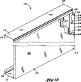
図6,8,9に更に示すように、パネル部材62は頂部キャップ58の金属板18と離間して設けられる上端部を含む。これらにより間隙70が頂部キャップ58の金属板18及びパネル部材62の上端部間に画定される。好適にはこれらの間隙70により、下部トラックに対する間柱材34の収縮が許容され、この機能は温度の著しい低下において発揮される。これにより間隙70はパネル部材62と頂部キャップ58との接触を防止する。これらの接触はパネル部材62の倒壊及び損傷のうち少なくともいずれか一方の原因となる。このため壁構造体10の密封性能は妥協される。いかなる間隙70が形成されるかは任意だが、間隙70は好適にはパネル部材62の上端部及び頂部キャップ58の金属板18間にて約4分の3インチ(約1.905cm)である。壁構造体10の耐火性能は間隙70内に成型材料60を設けることにより更に高められる。いかなる成型材料60が使用されるかは任意だが、成型材料60は好適には耐火性を備える成型材料60や難燃性を備える成型材料60であり、これにより熱に抵抗し、金属フレーム構造体の適切な膨張が可能となる。
As further shown in FIGS. 6, 8, and 9, the
図8,9から明らかなように頂部キャップ58は、略平坦にして、且つ平面から成る金属板18から構成され、金属板18は一対の対向する平行な長尺状の端部22を画定する。金属板18と直交して外方に向かって延びるものは、一対の略平坦にして、且つ平面から成る側壁24であり、側壁24は好適には金属板18と一体的に形成される。頂部キャップ58は一対の対向するオスの突出部28を更に含み、突出部28は平行にして、且つ内側に配向され、各側壁24と一体的に形成される。これらのオスの突出部28は長尺状の端部22のそれぞれと離間して設けられる側壁24に沿って連続して延びる。上述したようにオスの突出部28はそれぞれ好適にはV字型の断面を有する。
As is apparent from FIGS. 8 and 9, the
頂部キャップ58は好適には側壁24の少なくとも1つが頂部トラック16の側壁24と部分66にて少なくとも部分的に重合するように構成される。更に、頂部キャップ58は好適には側壁24間に幅を画定する。幅は壁構造体10の両側に設けられる対向するパネル部材62を横断する幅と釣り合う。より具体的には頂部キャップ58は好適には、側壁24のオスの突出部28及び頂部キャップ58がパネル部材62の外側表面を摺動して支持し、壁構造体10を密封するように構成される。
The
図7,10,11に、間柱材34の固定部46に取り付けられる間柱材キャップ54を更に備える壁構造体10を示す。図から明らかなように、間柱材キャップ54は好適には滑動延伸部38に連結しないようにして、重合する関係により設けられ、機械的留め具64(即ち、タッピンネジ)を使用する等して固定部46にのみ連結される。間柱材キャップ54は金属板18を備える。金属板18は、金属板18と直交しそこから外方に向かって延びる一対の側壁24を有する。この点に関して、間柱材キャップ54は通常溝状の断面である。間柱材キャップ54は固定部46にて間柱材34に連結される。より具体的には間柱材キャップ54は少なくとも1つの機械的留め具64を使用して、間柱材キャップ54の側壁24を間柱材34の固定部46の側壁24に相互に連結させる。
7, 10, and 11 show the
図7,10,11に示すように間柱材キャップ54は通常方形の切り抜きである開口部56を更に含む。開口部56の形状は任意であるが、開口部56は留め具64が固定部46の側壁24を通過してスロット44内に延びるように、好適な寸法に形成され、スロット44に対して好適な位置に配置される。このようにして間柱材キャップ54は固定部46内における滑動延伸部38の軸方向の移動を規制することなく間柱材34に確実に取り付けられる。これらにより隣接するパネル部材62は留め具64がパネル部材62を通過して間柱材34に隣接する側壁24の部分内に挿入されることにより図11に示すパネル部材62に固定される。
As shown in FIGS. 7, 10, and 11, the
防火壁構造体10の組立及び作業を図面を参照して後述する。最初に頂部トラック16及び底部トラック14が相互に離間して設けられる。この点に関して頂部トラック16及び底部トラック14は、壁構造体10が組み立てられる床及び天井間の計測に従って床等の平坦な面に沿って配置される。これに代えて、頂部トラック16及び底部トラック14は床及び天井のそれぞれに沿って相互に一般的な配置により取り付けられてもよい。機械的留め具64は頂部トラック16及び底部トラック14の金属板18を通過して床及び天井のそれぞれの内部に延び、頂部トラック16及び底部トラック14をそれぞれに対して固定してもよい。
The assembly and work of the
間柱材の組立及び設置において滑動延伸部38の1つは固定部46の1つの内部に摺動自在に挿入され、これにより間柱材34の対向する終端部26に形成されるメスの凹部52は頂部トラック16及び底部トラック14に沿って形成されるオスの突出部28に対して係合する。好適には、間柱材34は通常頂部トラック16及び底部トラック14に対して横断方向に、或いは直交するように配向される。滑動延伸部38が固定部46に対して摺動自在である性質により、間柱材34は頂部トラック16及び底部トラック14間に間隙を設けるように調整される。間隙により床から天井までの高さの変化を収容し、この機能は欠陥工事及び建物の定着のうち少なくともいずれか一方において発揮される。
In the assembly and installation of the stud member, one of the sliding and extending
より具体的には間柱材34のそれぞれに組み込まれる伸縮機構36により、固定部46に対する滑動延伸部38の伸縮が可能となる。これにより間柱材34の長さを調整し、床から天井までの高さに適合させる。頂部トラック16及び底部トラック14への間柱材34の設置において、発明の名称が「構造部材及びその連結構造体」である係属中の米国特許出願第09/979214号明細書に詳細に開示されているように、セルフタッピンネジ等の機械的留め具64はオスの突出部28の隣接する領域に挿入され、頂部トラック16及び底部トラック14の側壁24を間柱材34の側壁24に、これらの対向する終端部26にて固定する。
More specifically, the sliding / extending
好適には頂部キャップ58は通常頂部トラック16に隣接して設けられ、これにより各金属板18が接触して係合する。パネル部材62はパネル部材62の下端部が、離間して設けられた複数の留め具64により底部トラック14の側壁24に固定されるように壁構造体10に取り付けられる。同様に留め具64はパネル部材62を通過して固定部46の側壁24内に延び、パネル部材62を間柱材34及び底部トラック14に移動不能に固定する。更に、少なくとも1つの機械的留め具64は留め具64が滑動延伸部38に形成されるスロット44内に延びるようにパネル部材62を通過し固定部46の側壁24を通過して延びる。
Preferably, a
理想的にはパネル部材62はその上端部が頂部キャップ58の金属板18に対して離間して設けられるように好適な寸法に形成され、構成される。図8,9に示すようにパネル部材62の上端部及び頂部キャップ58の金属板18の間に画定される間隙70には耐火性を備えた成型材料60が挿入される。好適にはこれらの耐火性を備えた成型材料60は更に弾性を備えパネル部材62の上端部及び頂部キャップ58の相互に対する移動を収容する。更に、頂部キャップ58は頂部キャップ58の側壁24に沿って形成されるオスの突出部がパネル部材62に連続して接触するように設けられるような好適な幅である。
Ideally, the
任意により図7,10に示すように間柱材キャップ54はパネル部材62の設置に先立って間柱材34に設置されてもよい。これらの構成において、間柱材キャップ54の開口部56は滑動延伸部38に形成されるスロット44に好適に並べられる。これにより留め具64が開口部56を通過してスロット44内に延びても、間柱材34の滑動延伸部38と固定部46との相互に対する運動は規制されない。
Optionally, as shown in FIGS. 7 and 10, the
図2に示すように突出部20が任意により底部トラック14の金属板18に設けられてもよい。これらの突出部20は金属板18の暴露されている側に形成される節や隆起部の形状であってもよく、好適には間柱材34の上部終端部26及び下部終端部26のうち少なくともいずれか一方と係合可能なグリップ特性を備えるように構成される。突出部20は金属板18の底面からパンチにより形成可能だが、その他の金属成形方法が突出部を形成するために使用可能である。発明の名称が「グリップ特性を備えた構造部材及びその連結構造体」である係属中の米国特許出願第11/146534号明細書に開示されているように、これらの突出部20は間柱材34の上部終端部26や下部終端部26の摺動、滑動及び/又は移動を防止するように構成される。この点に関して、これらの突出部20は頂部トラック16の金属板19に付加的に形成されてもよいものといえる。上部トラック16及び底部トラック14と間柱材34との間に好適な量の摩擦による効果及びグリップによる効果が得られるように、突出部20の高さ、寸法、間隙、及び単位面積当たりの数を調整することが求められる。
As shown in FIG. 2, the
本発明の付加的な変形及び改良が当業者には更に明らかである。従って、ここで開示された部分の組み合わせは本発明の実施例を示すことを意図したものに過ぎず、本発明の精神及び範囲内における装置の別例を制限することを意図したものではない。 Additional variations and modifications of the invention will be further apparent to those skilled in the art. Accordingly, the combinations of parts disclosed herein are merely intended to illustrate embodiments of the present invention and are not intended to limit other examples of devices within the spirit and scope of the present invention.
Claims (5)
対向する一対の平行な長尺状の端部によって画定される平面から成る金属板と、
内側に配向され、対向する一対の平行なオスの突出部と、同突出部は長尺状の端部のそれぞれと一体的に形成され、各長尺状の端部に沿って連続的に延びることと、各オスの突出部はV字型の断面を有することと、
一対の平坦にして、且つ平面から成る側壁とを含み、同側壁は各オスの突出部と一体的に形成され、金属板に対して直交して対応するオスの突出部から外方に向かって延びることと、前記頂部トラックおよび底部トラックは頂部トラックの側壁が底部トラックの側壁に対向するように配向されることと、
少なくとも1つの間柱材とを備え、同間柱材は頂部トラック及び底部トラックを横断して直交して相互に連結するように調整されることと、同間柱材は溝状の断面と対向する一対の終端部とを有し、更に、
固定部内にて少なくとも部分的に重合する滑動延伸部を備える伸縮機構を含み、同伸縮機構により間柱材は伸縮して頂部トラック及び底部トラック間の間隙の変化を収容することと、
滑動延伸部及び固定部はそれぞれ溝状の断面と対向する終端部とを有し、滑動延伸部及び固定部のそれぞれの終端部のうち1つは頂部トラック及び底部トラックのうち少なくとも1つに固定されることと、滑動延伸部及び固定部はそれぞれ、
対向する一対の平行な長尺状の端部によって画定される平坦にして、且つ平面から成る金属板と、
一対の平坦にして、且つ平面から成る側壁と、同側壁は金属板と一体的に形成され、金属板から直交する方向へ外方に向かって長尺状の端部に沿って延びることと、側壁はそれぞれ一対の対向する側端部を画定し、同側端部は通常長尺状の端部に対して直交す
るように配向されることと、
一対の平坦にして、且つ平面から成るフランジとを含み、各フランジは対応する側壁から直交する方向に延びて内側に指向し、相互に同一平面上にあることと、
滑動延伸部は側壁の少なくとも1つに形成されるスロットを含むことと、同スロットは留め具が内部に延びて滑動延伸部を固定部に対して摺動自在とするような寸法に形成され構成されることと、
固定部は金属板に形成され相互に離間して設けられる複数の係止パターンを含み、同係止パターンは滑動延伸部と係合し、滑動延伸部の固定部に対する好適な軸方向の位置を保持するように構成されることと、同係止パターンは金属板から内側に延びる隆起した突出部として金属板と一体的に形成されることと、
滑動延伸部及び固定部はそれぞれ内側に配向されて対向する一対の平行なメスの凹部を含み、同凹部は側端部に沿って終端部の1つにて側壁に形成されることと、各メスの凹部はV字型の断面を有し、頂部トラック及び底部トラックのオスの突出部をそれぞれ受承するように調整されることとを特徴とする防火壁構造体。The elongated top track and bottom track, the top track and the bottom track are adjusted so as to be arranged along the surface, respectively, are provided in parallel and spaced apart from each other, and the top track and the bottom track are Each having a groove-like cross-section and an end portion facing each other;
A metal plate consisting of a plane defined by a pair of opposing elongated parallel ends;
A pair of parallel male projections oriented inward and opposite, and the projections are formed integrally with each of the elongated ends and continuously extend along each elongated end. And that each male protrusion has a V-shaped cross section,
And a pair of Tan Taira, and includes a side wall consisting of plane, the side wall is integrally formed with the projecting portion of the male, outward from the projecting portion of the male corresponding perpendicular to the metal plate The top track and the bottom track are oriented such that the side wall of the top track faces the side wall of the bottom track;
At least one interstitial column member, the interstitial column member being adjusted to be interconnected orthogonally across the top track and the bottom track, and the interstitial column member is paired with a groove-shaped cross section. An end portion, and
Including a telescopic mechanism comprising a sliding and extending portion that at least partially superposes within the fixed portion, and by the telescopic mechanism, the stud material expands and contracts to accommodate a change in the gap between the top track and the bottom track;
Each of the sliding extension part and the fixed part has a groove-shaped cross section and a terminal part facing each other, and one of the terminal parts of each of the sliding extension part and the fixing part is fixed to at least one of the top track and the bottom track. And the sliding extension part and the fixing part are respectively
In the by Ru Tan Taira defined by the ends of a pair of parallel elongated opposing, a metal plate and made of planes,
And a pair of Tan Taira, and a side wall consisting of plane, the side wall is formed to the metal plate integrally and extend along the elongated end portion outwardly in a direction perpendicular from the metal plate Each of the side walls defines a pair of opposing side edges, the same side edges being normally oriented perpendicular to the elongated end;
And that in the pair of Tan Taira, and includes a flange consisting of a plane, each flange directed inwardly extend in a direction perpendicular from the corresponding side wall, it is mutually coplanar,
The sliding extension includes a slot formed in at least one of the side walls, and the slot is sized and configured such that the fastener extends therein to allow the sliding extension to slide relative to the fixed part. And
The fixing portion includes a plurality of locking patterns formed on the metal plate and spaced apart from each other. The locking pattern engages with the sliding extension portion, and has a suitable axial position with respect to the fixing portion of the sliding extension portion. Configured to hold, and the locking pattern is integrally formed with the metal plate as a raised protrusion extending inwardly from the metal plate;
Each of the sliding extension portion and the fixing portion includes a pair of parallel female recesses that are oriented inward and face each other, and the recesses are formed in the side wall at one of the end portions along the side end portions, A fire wall structure characterized in that the female recess has a V-shaped cross section and is adjusted to receive the male protrusions of the top and bottom tracks, respectively.
一対の対向する平行な長尺状の端部によって画定される平坦にして、且つ平面から成る金属板と、該頂部キャップは頂部トラックの金属板と隣接して設けられることと、
該金属板と一体的に形成され、同金属板から直交する方向に延びて外方に指向する、一対の平坦にして、且つ平面から成る側壁と、
内側に配向され、対向する一対の平行なオスの突出部とから成り、各突出部は対応する側壁と一体的に形成され、対応する長尺状の端部に対して離間して側壁に沿って連続して延び、各オスの突出部はV字型の断面を有することと、前記頂部キャップは頂部キャップの側壁の少なくとも1つが頂部トラックの側壁と少なくとも部分的に重合するように構成されることとを特徴とする請求項1に記載の壁構造体。Comprising an elongated top cap which is fixed by the relationship of polymerization to the metal plate of the top track has a groove-shaped end surface, the top cap,
In the by Ru Tan Taira defined by parallel elongated end a pair of opposed, a metal plate and made of planes, and that said top cap is provided adjacent to the metal plate of the top track,
Is formed the metal plate and integrally directed outwardly extend in a direction perpendicular from the same metal plate, and a pair of Tan Taira, a side wall made and from the plane,
It consists of a pair of opposing parallel male projections oriented inwardly, each projection being formed integrally with the corresponding side wall, spaced along the side wall with a corresponding elongated end Each male protrusion has a V-shaped cross section, and the top cap is configured such that at least one of the top cap sidewalls at least partially overlaps with the top track sidewall. The wall structure according to claim 1 .
Applications Claiming Priority (5)
| Application Number | Priority Date | Filing Date | Title |
|---|---|---|---|
| US78009906P | 2006-03-08 | 2006-03-08 | |
| US60/780,099 | 2006-03-08 | ||
| US11/483,791 US20070209306A1 (en) | 2006-03-08 | 2006-07-10 | Fire rated wall structure |
| US11/483,791 | 2006-07-10 | ||
| PCT/US2007/005621 WO2007103331A2 (en) | 2006-03-08 | 2007-03-06 | Fire rated wall structure |
Publications (2)
| Publication Number | Publication Date |
|---|---|
| JP2009529108A JP2009529108A (en) | 2009-08-13 |
| JP5156889B2 true JP5156889B2 (en) | 2013-03-06 |
Family
ID=38475476
Family Applications (1)
| Application Number | Title | Priority Date | Filing Date |
|---|---|---|---|
| JP2008558340A Expired - Fee Related JP5156889B2 (en) | 2006-03-08 | 2007-03-06 | Firewall structure |
Country Status (10)
| Country | Link |
|---|---|
| US (1) | US20070209306A1 (en) |
| EP (1) | EP1994237A4 (en) |
| JP (1) | JP5156889B2 (en) |
| KR (1) | KR20090031497A (en) |
| AU (1) | AU2007224043A1 (en) |
| BR (1) | BRPI0708695A2 (en) |
| CA (1) | CA2647054A1 (en) |
| MX (1) | MX2008011348A (en) |
| RU (1) | RU2008139909A (en) |
| WO (1) | WO2007103331A2 (en) |
Families Citing this family (61)
| Publication number | Priority date | Publication date | Assignee | Title |
|---|---|---|---|---|
| US20080178782A1 (en) * | 2007-01-26 | 2008-07-31 | Frobosilo Raymond C | Wall construction |
| US10563399B2 (en) | 2007-08-06 | 2020-02-18 | California Expanded Metal Products Company | Two-piece track system |
| US8555566B2 (en) | 2007-08-06 | 2013-10-15 | California Expanded Metal Products Company | Two-piece track system |
| US7752817B2 (en) | 2007-08-06 | 2010-07-13 | California Expanded Metal Products Company | Two-piece track system |
| US8087205B2 (en) | 2007-08-22 | 2012-01-03 | California Expanded Metal Products Company | Fire-rated wall construction product |
| US10619347B2 (en) | 2007-08-22 | 2020-04-14 | California Expanded Metal Products Company | Fire-rated wall and ceiling system |
| US7617643B2 (en) | 2007-08-22 | 2009-11-17 | California Expanded Metal Products Company | Fire-rated wall construction product |
| US7681365B2 (en) | 2007-10-04 | 2010-03-23 | James Alan Klein | Head-of-wall fireblock systems and related wall assemblies |
| US7866108B2 (en) | 2007-10-04 | 2011-01-11 | Klein James A | Head-of-wall fireblock systems and related wall assemblies |
| US8151526B2 (en) | 2007-10-04 | 2012-04-10 | Klein James A | Head-of-wall fireblock systems and related wall assemblies |
| EP2090705B1 (en) | 2008-02-13 | 2011-12-14 | Profilform A/S | A track and stud framing system for a drywall construction |
| US8061099B2 (en) * | 2009-05-19 | 2011-11-22 | Tsf Systems, Llc | Vertical deflection extension end member |
| US8671632B2 (en) | 2009-09-21 | 2014-03-18 | California Expanded Metal Products Company | Wall gap fire block device, system and method |
| US10184246B2 (en) | 2010-04-08 | 2019-01-22 | California Expanded Metal Products Company | Fire-rated wall construction product |
| US8793947B2 (en) | 2010-04-08 | 2014-08-05 | California Expanded Metal Products Company | Fire-rated wall construction product |
| US9683364B2 (en) | 2010-04-08 | 2017-06-20 | California Expanded Metal Products Company | Fire-rated wall construction product |
| US20110296778A1 (en) * | 2010-06-08 | 2011-12-08 | Collins Arlan E | Pre-manufactured utility wall |
| US8950132B2 (en) | 2010-06-08 | 2015-02-10 | Innovative Building Technologies, Llc | Premanufactured structures for constructing buildings |
| US9493940B2 (en) | 2010-06-08 | 2016-11-15 | Innovative Building Technologies, Llc | Slab construction system and method for constructing multi-story buildings using pre-manufactured structures |
| US9027307B2 (en) | 2010-06-08 | 2015-05-12 | Innovative Building Technologies, Llc | Construction system and method for constructing buildings using premanufactured structures |
| US20120144774A1 (en) * | 2010-12-09 | 2012-06-14 | Andrews William J | Fire rated wall structure |
| EA201490504A1 (en) * | 2011-09-23 | 2014-08-29 | Илья Морозов | ADJUSTABLE WALL FRAME RACK |
| US9523193B2 (en) | 2012-01-20 | 2016-12-20 | California Expanded Metal Products Company | Fire-rated joint system |
| US9045899B2 (en) | 2012-01-20 | 2015-06-02 | California Expanded Metal Products Company | Fire-rated joint system |
| US10077550B2 (en) | 2012-01-20 | 2018-09-18 | California Expanded Metal Products Company | Fire-rated joint system |
| US8826599B2 (en) * | 2012-02-10 | 2014-09-09 | Specified Technologies Inc. | Insulating gasket construction for head-of-wall joints |
| US8997424B1 (en) * | 2012-10-27 | 2015-04-07 | Convergent Market Research, Inc. | Structural wall panel for use in light-frame construction and method of construction employing structural wall panels |
| KR101481790B1 (en) * | 2013-07-03 | 2015-01-12 | 삼아디오시스템 주식회사 | Fire wall assembly and bracket structure for the same |
| EP3011122B1 (en) | 2014-08-30 | 2017-08-16 | Innovative Building Technologies LLC | Closure piece for installing the track of a sliding door and method of using it |
| KR101991055B1 (en) | 2014-08-30 | 2019-06-19 | 이노베이티브 빌딩 테크놀러지스 엘엘씨 | Floor and ceiling panel for use in buildings |
| US10364572B2 (en) | 2014-08-30 | 2019-07-30 | Innovative Building Technologies, Llc | Prefabricated wall panel for utility installation |
| JP6186085B2 (en) | 2014-08-30 | 2017-08-30 | イノベイティブ ビルディング テクノロジーズ,エルエルシー | Prefabricated partition and end walls |
| US10260250B2 (en) | 2014-08-30 | 2019-04-16 | Innovative Building Technologies, Llc | Diaphragm to lateral support coupling in a structure |
| US9879421B2 (en) | 2014-10-06 | 2018-01-30 | California Expanded Metal Products Company | Fire-resistant angle and related assemblies |
| US9752318B2 (en) | 2015-01-16 | 2017-09-05 | California Expanded Metal Products Company | Fire blocking reveal |
| US10000923B2 (en) | 2015-01-16 | 2018-06-19 | California Expanded Metal Products Company | Fire blocking reveal |
| US9551148B2 (en) | 2015-01-27 | 2017-01-24 | California Expanded Metal Products Company | Header track with stud retention feature |
| US10676923B2 (en) | 2016-03-07 | 2020-06-09 | Innovative Building Technologies, Llc | Waterproofing assemblies and prefabricated wall panels including the same |
| KR102195715B1 (en) | 2016-03-07 | 2020-12-29 | 이노베이티브 빌딩 테크놀러지스 엘엘씨 | Prefabricated dimming wall with exterior conduit engagement features |
| AU2017229473B2 (en) | 2016-03-07 | 2019-08-08 | Innovative Building Technologies, Llc | A pre-assembled wall panel for utility installation |
| EP3426982A4 (en) | 2016-03-07 | 2019-10-16 | Innovative Building Technologies LLC | Floor and ceiling panel for slab-free floor system of a building |
| US9790686B1 (en) * | 2016-08-10 | 2017-10-17 | United States Gypsum Company | Triangular stud shaft wall system |
| US11486150B2 (en) | 2016-12-20 | 2022-11-01 | Clarkwestern Dietrich Building Systems Llc | Finishing accessory with backing strip |
| US10487493B2 (en) | 2017-05-12 | 2019-11-26 | Innovative Building Technologies, Llc | Building design and construction using prefabricated components |
| US11098475B2 (en) | 2017-05-12 | 2021-08-24 | Innovative Building Technologies, Llc | Building system with a diaphragm provided by pre-fabricated floor panels |
| US10323428B2 (en) | 2017-05-12 | 2019-06-18 | Innovative Building Technologies, Llc | Sequence for constructing a building from prefabricated components |
| US10724228B2 (en) | 2017-05-12 | 2020-07-28 | Innovative Building Technologies, Llc | Building assemblies and methods for constructing a building using pre-assembled floor-ceiling panels and walls |
| CN109424086B (en) * | 2017-08-21 | 2020-10-27 | 北新集团建材股份有限公司 | Assembled wall and mounting method thereof |
| WO2019091540A1 (en) * | 2017-11-13 | 2019-05-16 | Knauf Gips Kg | Profile and construction element set for arranging a component for a drywall construction, and drywall formed therewith |
| US10753084B2 (en) | 2018-03-15 | 2020-08-25 | California Expanded Metal Products Company | Fire-rated joint component and wall assembly |
| US10689842B2 (en) | 2018-03-15 | 2020-06-23 | California Expanded Metal Products Company | Multi-layer fire-rated joint component |
| US11162259B2 (en) | 2018-04-30 | 2021-11-02 | California Expanded Metal Products Company | Mechanically fastened firestop flute plug |
| US11111666B2 (en) | 2018-08-16 | 2021-09-07 | California Expanded Metal Products Company | Fire or sound blocking components and wall assemblies with fire or sound blocking components |
| US10914065B2 (en) | 2019-01-24 | 2021-02-09 | California Expanded Metal Products Company | Wall joint or sound block component and wall assemblies |
| US11268274B2 (en) | 2019-03-04 | 2022-03-08 | California Expanded Metal Products Company | Two-piece deflection drift angle |
| CN110241948B (en) * | 2019-05-22 | 2020-09-08 | 安徽森泰木塑集团股份有限公司 | Modular wall shifting and fixing mode |
| US11920343B2 (en) | 2019-12-02 | 2024-03-05 | Cemco, Llc | Fire-rated wall joint component and related assemblies |
| CN112031263B (en) * | 2020-08-21 | 2022-06-10 | 台州学院 | Anti assembled blast wall that splits of combatting earthquake |
| US11885138B2 (en) | 2020-11-12 | 2024-01-30 | Clarkwestern Dietrich Building Systems Llc | Control joint |
| USD1026252S1 (en) | 2020-11-12 | 2024-05-07 | Clarkwestern Dietrich Building Systems Llc | Control joint |
| US12031326B2 (en) * | 2022-03-23 | 2024-07-09 | Changda Construction Technology Co., Ltd. | Structural energy-saving, heat-insulated and decorative integrated plate and manufacturing method therefor |
Family Cites Families (101)
| Publication number | Priority date | Publication date | Assignee | Title |
|---|---|---|---|---|
| US3125193A (en) * | 1964-03-17 | Movable partition systems | ||
| US2225574A (en) * | 1940-12-17 | Framing and furring structure for | ||
| US2058386A (en) * | 1932-10-20 | 1936-10-20 | Johns Manville | Wall assembly |
| US2173721A (en) * | 1938-09-09 | 1939-09-19 | Cons Expanded Metal Companies | Wall construction |
| US2333289A (en) * | 1943-04-06 | 1943-11-02 | Hopeman Bros Inc | Ship joiner bulkhead |
| US2796158A (en) * | 1947-10-22 | 1957-06-18 | Johns Manville | Wall assembly |
| US2843725A (en) * | 1955-03-24 | 1958-07-15 | Smith Corp A O | Box section and method of making |
| US2966708A (en) * | 1956-10-29 | 1961-01-03 | Joseph O Theriot | Stud anchor plate |
| US3217452A (en) * | 1961-06-28 | 1965-11-16 | Melvin A Steele | Wall and partition construction |
| US3234697A (en) * | 1961-12-22 | 1966-02-15 | Andrew J Toti | Awning construction |
| US3312032A (en) * | 1963-07-05 | 1967-04-04 | Ames Taping Tool Systems Mfg C | Metal stud and panel |
| US3160280A (en) * | 1963-08-12 | 1964-12-08 | Gen Electric | Device for mounting apparatus |
| US3332197A (en) * | 1964-06-30 | 1967-07-25 | James L Hinkle | Interlocked structural assemblies and stiffeners therefor |
| US3397495A (en) * | 1966-01-19 | 1968-08-20 | Angeles Metal Trim Co | Partition wall with yieldable cap members |
| BE756345A (en) * | 1969-09-18 | 1971-03-01 | Naegele Feinmaschinenbau | PROCESS FOR MANUFACTURING AND FIXING OF LIMITING ELEMENTS OF SLIDING CLOSURES AND DEVICE FOR IMPLEMENTING THE PROCESS |
| US3685863A (en) * | 1969-10-30 | 1972-08-22 | Hans Oetiker | Structural elements |
| US3690082A (en) * | 1970-02-24 | 1972-09-12 | Futuristic Building Products I | Door frame |
| US3665837A (en) * | 1970-05-13 | 1972-05-30 | Chicago Metallic Corp | Lineal air diffuser bar |
| US3719980A (en) * | 1970-06-10 | 1973-03-13 | Bussel P Van | Method of making a peripherally grooved sheet metal article |
| US3753328A (en) * | 1971-06-08 | 1973-08-21 | W Papsco | Method of installing modular wall construction |
| US3753324A (en) * | 1971-12-10 | 1973-08-21 | J Puccio | Metal stud assembly |
| AU475452B2 (en) * | 1972-03-13 | 1974-09-12 | Whisson, H.J. | Fabricated partitions |
| CA965217A (en) * | 1972-10-26 | 1975-04-01 | Domtar Limited | Partition mounting |
| US3861103A (en) * | 1973-03-02 | 1975-01-21 | Robert R Rasmussen | Partitioning arrangement for high rise buildings |
| US3845601A (en) * | 1973-10-17 | 1974-11-05 | Bethlehem Steel Corp | Metal wall framing system |
| US4018020A (en) * | 1973-11-01 | 1977-04-19 | Roblin Industries, Inc. | Modular wall construction |
| US4074487A (en) * | 1974-01-28 | 1978-02-21 | Kaiser Steel Corporation | Multi-story wall framing system and method |
| US4038799A (en) * | 1975-04-30 | 1977-08-02 | Frigitemp Corporation | Joiner bulkhead method and apparatus |
| US4019291A (en) * | 1975-10-14 | 1977-04-26 | American Store Equipment Corporation | Wall system |
| US4272930A (en) * | 1975-11-04 | 1981-06-16 | Roy H. Smith, Jr. | Modular housing system |
| US4397127A (en) * | 1980-09-22 | 1983-08-09 | Donn, Incorporated | Extendable stud for partition walls or the like |
| NZ210863A (en) * | 1985-01-17 | 1988-03-30 | Onteam Ltd | Wall frame: interconnected metal studs and plates |
| US4854096A (en) * | 1986-04-14 | 1989-08-08 | Smolik Robert A | Wall assembly |
| US4757657A (en) * | 1986-06-02 | 1988-07-19 | Architectural Wall Systems, Inc. | Floor-to-ceiling wall system |
| US4709517A (en) * | 1986-06-02 | 1987-12-01 | Architectural Wall Systems, Inc. | Floor-to-ceiling wall system |
| US4734971A (en) * | 1987-01-12 | 1988-04-05 | Aro Metal Stamping Co., Inc. | Method of mechanically crimping overlapping sheet metal |
| US4760682A (en) * | 1987-05-05 | 1988-08-02 | S & K Enterprises Inc. | Tubular rack beam and method of making same |
| US4798029A (en) * | 1987-11-30 | 1989-01-17 | Fibergrate Corporation | Hold-down clamp |
| EP0321183B1 (en) * | 1987-12-16 | 1992-03-11 | Alexandros Karytinos | Building frame construction |
| US5157883A (en) * | 1989-05-08 | 1992-10-27 | Allan Meyer | Metal frames |
| US5081813A (en) * | 1990-02-27 | 1992-01-21 | Allied Constructions Pty. Limited | Metal wall frame structure |
| US5040345A (en) * | 1990-04-27 | 1991-08-20 | Gilmour Michael F | Stud clip for allowing vertical floating movement of a floor or roof structure |
| US5079884A (en) * | 1990-06-04 | 1992-01-14 | National Gypsum Company | Extendible interconnected Z-studs |
| US5127760A (en) * | 1990-07-26 | 1992-07-07 | Brady Todd A | Vertically slotted header |
| US5095678A (en) * | 1991-01-23 | 1992-03-17 | Steelway Housing | Structural stud |
| US5203132A (en) * | 1991-09-17 | 1993-04-20 | Smolik Robert A | Wall assembly |
| JP2745171B2 (en) * | 1991-10-03 | 1998-04-28 | 株式会社フジタ | Fire protection unit |
| US5222335A (en) * | 1992-06-26 | 1993-06-29 | Anthony Petrecca | Metal track system for metal studs |
| US5285615A (en) * | 1992-10-26 | 1994-02-15 | Angeles Metal Systems | Thermal metallic building stud |
| US5720138A (en) * | 1992-11-12 | 1998-02-24 | Johnson; David L. | Metallic wall framing, method and apparatus for producing same |
| US5394665A (en) * | 1993-11-05 | 1995-03-07 | Gary Johnson | Stud wall framing construction |
| US5755066A (en) * | 1993-12-02 | 1998-05-26 | Becker; Duane William | Slip track assembly |
| US5497591A (en) * | 1994-01-11 | 1996-03-12 | Mitek Holdings, Inc. | Metal wall framing |
| US5596859A (en) * | 1994-09-20 | 1997-01-28 | Horton; Jim W. | Metal wall stud |
| US5592796A (en) * | 1994-12-09 | 1997-01-14 | Landers; Leroy A. | Thermally-improved metallic framing assembly |
| US5600991A (en) * | 1995-02-10 | 1997-02-11 | Ogihara America Corporation | Stretch controlled forming mechanism and method for forming multiple gauge welded blanks |
| US5649688A (en) * | 1995-02-17 | 1997-07-22 | Baker; Neill E. | Railings with continuous spacers |
| IT1280293B1 (en) * | 1995-03-23 | 1998-01-08 | Sapim Amada Spa | PROCEDURE FOR THE REALIZATION OF REINFORCEMENT PROFILES ON SHEET PANELS |
| US5797233A (en) * | 1995-12-29 | 1998-08-25 | Hascall; Karl B. | Pre-spaced time-saving track for mounting studs for construction of drywall and other wall surfaces |
| US5685121A (en) * | 1996-02-16 | 1997-11-11 | Defrancesco; Frank | Metal stud |
| JP3741474B2 (en) * | 1996-02-23 | 2006-02-01 | 株式会社小松製作所 | Bending order selection method and selection apparatus for bending machine |
| US5729950A (en) * | 1996-04-03 | 1998-03-24 | Hardy Industries, Inc. | All-metal reinforcing building frame |
| US5735100A (en) * | 1996-10-07 | 1998-04-07 | 527233 B.C. Ltd. | Folding telescopic prefabricated framing units for non-load-bearing walls |
| US20040055232A1 (en) * | 1997-09-11 | 2004-03-25 | Roger Jette | Raised floor system and support apparatus |
| UY25210A1 (en) * | 1997-10-16 | 1999-04-09 | Cosma Int Inc | DEFORMATION STAMPING DIE FOR THE STAMPING OF BODY PANELS OF MOTOR VEHICLES. |
| US6029334A (en) * | 1997-12-02 | 2000-02-29 | Unova Ip Corp. | Hemming method and apparatus |
| US5930968A (en) * | 1997-12-24 | 1999-08-03 | Pullam; Billy D. | Interlocking stubs |
| US5950385A (en) * | 1998-03-11 | 1999-09-14 | Herren; Thomas R. | Interior shaft wall construction |
| US6023898A (en) * | 1998-06-01 | 2000-02-15 | Ground Star, Llc | Metal frame building construction |
| AUPP418498A0 (en) * | 1998-06-17 | 1998-07-09 | Rudduck, Dickory | Improved stud |
| US6119430A (en) * | 1998-09-25 | 2000-09-19 | Nicholls; J. Robert | Method and apparatus for an adjustable building stud |
| US20040083665A1 (en) * | 1999-04-16 | 2004-05-06 | Surowiecki Matt F. | Structural walls |
| US6374558B1 (en) * | 1999-04-16 | 2002-04-23 | Matt Surowiecki | Wall beam and stud |
| AUPQ052199A0 (en) * | 1999-05-21 | 1999-06-17 | Wiltin Pty Ltd | Joining arrangements for structural members |
| US6983569B1 (en) * | 1999-08-09 | 2006-01-10 | Zev Rosenberg | Modular metal wall framing system |
| US6609285B1 (en) * | 1999-10-01 | 2003-08-26 | Herman Miller, Inc. | Process for manufacturing a support |
| US6401423B1 (en) * | 2000-02-10 | 2002-06-11 | B & D Industries | Deflector track tabs for positioning studs along the track |
| US6568138B1 (en) * | 2000-05-10 | 2003-05-27 | Exterior Systems, Inc. | Framing system and related framing section assembly |
| US6418682B1 (en) * | 2000-08-21 | 2002-07-16 | Bailey Metal Products Limited | Non-structural steel studs |
| US6920734B2 (en) * | 2000-08-31 | 2005-07-26 | Dietrich Industries, Inc. | Bridging system for off-module studs |
| US6453627B1 (en) * | 2000-10-10 | 2002-09-24 | Timothy Powers | Skirt assembly for manufactured housing units |
| US6792733B2 (en) * | 2001-05-16 | 2004-09-21 | Flex-Ability Concepts, L.L.C. | Deflection clip |
| US6647691B2 (en) * | 2001-06-15 | 2003-11-18 | Duane William Becker | Track arrangement for supporting wall studs; method; and, wall framework assembly |
| US20060144009A1 (en) * | 2001-06-20 | 2006-07-06 | Attalla Anthony P | Metal framing member with off site manufactured locking tabs |
| US20030033770A1 (en) * | 2001-08-20 | 2003-02-20 | Harel Kenneth N. | Drywall bead with knurled paper flaps |
| US6609344B2 (en) * | 2001-11-21 | 2003-08-26 | Eluterio Saldana | Connectors, tracks and system for smooth-faced metal framing |
| US6871470B1 (en) * | 2002-01-17 | 2005-03-29 | Donie Stover | Metal stud building system and method |
| US20030145537A1 (en) * | 2002-02-05 | 2003-08-07 | Geoff Bailey | Metal building stud and brick tie for a hybrid metal and timber framed building system |
| DE10208537A1 (en) * | 2002-02-27 | 2003-09-11 | Bosch Gmbh Robert | wiper arm |
| GB0212734D0 (en) * | 2002-05-31 | 2002-07-10 | Lafarge Plasterboard Ltd | Wall stud |
| DE10233008A1 (en) * | 2002-07-20 | 2004-02-12 | Nothelfer Gmbh | Process for material flow control when deep-drawing sheet metal and deep-drawing tool |
| US6748705B2 (en) * | 2002-08-21 | 2004-06-15 | Leszek Orszulak | Slotted M-track support |
| US6997026B2 (en) * | 2002-12-12 | 2006-02-14 | Engel Industries, Inc. | Quick change metal stud to hemmed track roll forming system |
| NO326411B1 (en) * | 2003-03-24 | 2008-12-01 | Johnny Espenes | Universal Bracket. |
| US20050034408A1 (en) * | 2003-07-30 | 2005-02-17 | Joseph Palumbo | Metal stud wall packaging system |
| US7137768B2 (en) * | 2003-10-10 | 2006-11-21 | Illinois Tool Works Inc | Fastener assembly |
| US7445682B2 (en) * | 2004-09-29 | 2008-11-04 | Ged Intergrated Solution, Inc. | Window component stock transferring |
| US20060096192A1 (en) * | 2004-11-05 | 2006-05-11 | Daudet Larry R | Building construction components |
| US7451573B2 (en) * | 2005-02-25 | 2008-11-18 | Leszek Orszulak | Slotted M-track beam structures and related wall assemblies |
| US20060283130A1 (en) * | 2005-06-07 | 2006-12-21 | William Andrews | Structural members with gripping features and joining arrangements therefor |
| US20070011971A1 (en) * | 2005-07-14 | 2007-01-18 | Sitkiewicz Christopher P | Wall framing assembly and method of securing a stud to a header or footer |
-
2006
- 2006-07-10 US US11/483,791 patent/US20070209306A1/en not_active Abandoned
-
2007
- 2007-03-06 RU RU2008139909/03A patent/RU2008139909A/en not_active Application Discontinuation
- 2007-03-06 WO PCT/US2007/005621 patent/WO2007103331A2/en active Application Filing
- 2007-03-06 AU AU2007224043A patent/AU2007224043A1/en not_active Abandoned
- 2007-03-06 CA CA002647054A patent/CA2647054A1/en not_active Abandoned
- 2007-03-06 JP JP2008558340A patent/JP5156889B2/en not_active Expired - Fee Related
- 2007-03-06 BR BRPI0708695-4A patent/BRPI0708695A2/en not_active IP Right Cessation
- 2007-03-06 EP EP07752334A patent/EP1994237A4/en not_active Withdrawn
- 2007-03-06 KR KR1020087024530A patent/KR20090031497A/en not_active Application Discontinuation
- 2007-03-06 MX MX2008011348A patent/MX2008011348A/en not_active Application Discontinuation
Also Published As
| Publication number | Publication date |
|---|---|
| JP2009529108A (en) | 2009-08-13 |
| EP1994237A2 (en) | 2008-11-26 |
| US20070209306A1 (en) | 2007-09-13 |
| CA2647054A1 (en) | 2007-09-13 |
| RU2008139909A (en) | 2010-04-20 |
| MX2008011348A (en) | 2009-02-11 |
| EP1994237A4 (en) | 2009-12-02 |
| WO2007103331A3 (en) | 2008-11-13 |
| WO2007103331A2 (en) | 2007-09-13 |
| BRPI0708695A2 (en) | 2011-06-07 |
| KR20090031497A (en) | 2009-03-26 |
| AU2007224043A1 (en) | 2007-09-13 |
Similar Documents
| Publication | Publication Date | Title |
|---|---|---|
| JP5156889B2 (en) | Firewall structure | |
| US6799404B2 (en) | Wall panel assembly and method of assembly | |
| US3381438A (en) | Reusable wall system | |
| JP6517155B2 (en) | A steer module that cooperates to form a temporary steer case | |
| JP6158079B2 (en) | Improvement of Evolving building structure | |
| KR101571468B1 (en) | Curtain Wall and Its Installation Method | |
| US20120144774A1 (en) | Fire rated wall structure | |
| KR100878145B1 (en) | Ceiling fixing tool for panel and ceiling panel assembling system including the same | |
| JP6177759B2 (en) | Oversized exterior wall panel | |
| AU2017101778B4 (en) | A firestopping device and associated method | |
| KR101346601B1 (en) | Dry wall system of panel type of building | |
| JP6341254B2 (en) | Fixing structure of plate material and construction method of fixing structure of the plate material | |
| JP2020139404A (en) | Fireproof structure | |
| US20150085474A1 (en) | Beam support | |
| EP4290033B1 (en) | A tubular smoke shaft section and a smoke shaft | |
| JP6238804B2 (en) | Beam-column connection structure of unit type building | |
| WO2023053832A1 (en) | Panel device | |
| KR20110103632A (en) | Drywall and installing method of the same | |
| WO2023054015A1 (en) | Panel installation structure | |
| SE541046C2 (en) | Wall element, building wall and methods for constructing such elements and walls | |
| JP7010459B2 (en) | building | |
| JP7074534B2 (en) | Wall structure of temporary building and its construction method | |
| JP6974006B2 (en) | building | |
| JP6465512B2 (en) | Panel fixing bracket, floor structure, floor construction method | |
| JP2020105811A (en) | Corner frame, corner cover, and mounting structure of projected corner column and corner cover |
Legal Events
| Date | Code | Title | Description |
|---|---|---|---|
| A621 | Written request for application examination |
Free format text: JAPANESE INTERMEDIATE CODE: A621 Effective date: 20100305 |
|
| A711 | Notification of change in applicant |
Free format text: JAPANESE INTERMEDIATE CODE: A711 Effective date: 20100615 |
|
| A521 | Request for written amendment filed |
Free format text: JAPANESE INTERMEDIATE CODE: A821 Effective date: 20100615 |
|
| A977 | Report on retrieval |
Free format text: JAPANESE INTERMEDIATE CODE: A971007 Effective date: 20111027 |
|
| A131 | Notification of reasons for refusal |
Free format text: JAPANESE INTERMEDIATE CODE: A131 Effective date: 20111220 |
|
| RD04 | Notification of resignation of power of attorney |
Free format text: JAPANESE INTERMEDIATE CODE: A7424 Effective date: 20120119 |
|
| A521 | Request for written amendment filed |
Free format text: JAPANESE INTERMEDIATE CODE: A523 Effective date: 20120316 |
|
| TRDD | Decision of grant or rejection written | ||
| A01 | Written decision to grant a patent or to grant a registration (utility model) |
Free format text: JAPANESE INTERMEDIATE CODE: A01 Effective date: 20120828 |
|
| A61 | First payment of annual fees (during grant procedure) |
Free format text: JAPANESE INTERMEDIATE CODE: A61 Effective date: 20120926 |
|
| A711 | Notification of change in applicant |
Free format text: JAPANESE INTERMEDIATE CODE: A711 Effective date: 20121120 |
|
| A521 | Request for written amendment filed |
Free format text: JAPANESE INTERMEDIATE CODE: A821 Effective date: 20121120 |
|
| R150 | Certificate of patent or registration of utility model |
Ref document number: 5156889 Country of ref document: JP Free format text: JAPANESE INTERMEDIATE CODE: R150 Free format text: JAPANESE INTERMEDIATE CODE: R150 |
|
| FPAY | Renewal fee payment (event date is renewal date of database) |
Free format text: PAYMENT UNTIL: 20151221 Year of fee payment: 3 |
|
| R250 | Receipt of annual fees |
Free format text: JAPANESE INTERMEDIATE CODE: R250 |
|
| R250 | Receipt of annual fees |
Free format text: JAPANESE INTERMEDIATE CODE: R250 |
|
| LAPS | Cancellation because of no payment of annual fees |