JP5156621B2 - Temperature control device for bubbler - Google Patents
Temperature control device for bubbler Download PDFInfo
- Publication number
- JP5156621B2 JP5156621B2 JP2008502141A JP2008502141A JP5156621B2 JP 5156621 B2 JP5156621 B2 JP 5156621B2 JP 2008502141 A JP2008502141 A JP 2008502141A JP 2008502141 A JP2008502141 A JP 2008502141A JP 5156621 B2 JP5156621 B2 JP 5156621B2
- Authority
- JP
- Japan
- Prior art keywords
- temperature control
- container
- temperature
- bubbler
- liquid
- Prior art date
- Legal status (The legal status is an assumption and is not a legal conclusion. Google has not performed a legal analysis and makes no representation as to the accuracy of the status listed.)
- Expired - Fee Related
Links
- 239000012530 fluid Substances 0.000 claims description 38
- 239000007788 liquid Substances 0.000 claims description 38
- 238000000034 method Methods 0.000 claims description 32
- 230000008569 process Effects 0.000 claims description 32
- 238000007789 sealing Methods 0.000 claims description 18
- 238000001816 cooling Methods 0.000 claims description 16
- 238000010438 heat treatment Methods 0.000 claims description 10
- 230000009471 action Effects 0.000 claims description 9
- 230000008859 change Effects 0.000 claims description 8
- 238000001704 evaporation Methods 0.000 claims description 7
- 230000008020 evaporation Effects 0.000 claims description 7
- 238000004891 communication Methods 0.000 claims description 5
- 230000004888 barrier function Effects 0.000 claims 1
- 239000000463 material Substances 0.000 description 23
- 238000002955 isolation Methods 0.000 description 19
- 239000007789 gas Substances 0.000 description 15
- 239000002243 precursor Substances 0.000 description 14
- 150000001875 compounds Chemical class 0.000 description 12
- 239000004065 semiconductor Substances 0.000 description 8
- XLYOFNOQVPJJNP-UHFFFAOYSA-N water Substances O XLYOFNOQVPJJNP-UHFFFAOYSA-N 0.000 description 8
- 229910052782 aluminium Inorganic materials 0.000 description 7
- XAGFODPZIPBFFR-UHFFFAOYSA-N aluminium Chemical compound [Al] XAGFODPZIPBFFR-UHFFFAOYSA-N 0.000 description 7
- 238000004519 manufacturing process Methods 0.000 description 6
- 229910001220 stainless steel Inorganic materials 0.000 description 6
- 239000010935 stainless steel Substances 0.000 description 6
- 235000012431 wafers Nutrition 0.000 description 5
- RYGMFSIKBFXOCR-UHFFFAOYSA-N Copper Chemical compound [Cu] RYGMFSIKBFXOCR-UHFFFAOYSA-N 0.000 description 4
- 229910052802 copper Inorganic materials 0.000 description 4
- 239000010949 copper Substances 0.000 description 4
- 239000007787 solid Substances 0.000 description 4
- 238000012546 transfer Methods 0.000 description 4
- 238000000231 atomic layer deposition Methods 0.000 description 3
- 239000012159 carrier gas Substances 0.000 description 3
- 239000013078 crystal Substances 0.000 description 3
- 238000005516 engineering process Methods 0.000 description 3
- 239000004033 plastic Substances 0.000 description 3
- 239000000126 substance Substances 0.000 description 3
- UDQTXCHQKHIQMH-KYGLGHNPSA-N (3ar,5s,6s,7r,7ar)-5-(difluoromethyl)-2-(ethylamino)-5,6,7,7a-tetrahydro-3ah-pyrano[3,2-d][1,3]thiazole-6,7-diol Chemical compound S1C(NCC)=N[C@H]2[C@@H]1O[C@H](C(F)F)[C@@H](O)[C@@H]2O UDQTXCHQKHIQMH-KYGLGHNPSA-N 0.000 description 2
- 229940125936 compound 42 Drugs 0.000 description 2
- 238000009833 condensation Methods 0.000 description 2
- 230000005494 condensation Effects 0.000 description 2
- 230000008878 coupling Effects 0.000 description 2
- 238000010168 coupling process Methods 0.000 description 2
- 238000005859 coupling reaction Methods 0.000 description 2
- 230000000694 effects Effects 0.000 description 2
- 239000013536 elastomeric material Substances 0.000 description 2
- 239000011810 insulating material Substances 0.000 description 2
- 229910052751 metal Inorganic materials 0.000 description 2
- 239000002184 metal Substances 0.000 description 2
- 238000002488 metal-organic chemical vapour deposition Methods 0.000 description 2
- 238000004513 sizing Methods 0.000 description 2
- XUIMIQQOPSSXEZ-UHFFFAOYSA-N Silicon Chemical compound [Si] XUIMIQQOPSSXEZ-UHFFFAOYSA-N 0.000 description 1
- 230000002411 adverse Effects 0.000 description 1
- 238000006243 chemical reaction Methods 0.000 description 1
- 239000004020 conductor Substances 0.000 description 1
- 230000007797 corrosion Effects 0.000 description 1
- 238000005260 corrosion Methods 0.000 description 1
- 230000001419 dependent effect Effects 0.000 description 1
- 238000005137 deposition process Methods 0.000 description 1
- 238000013461 design Methods 0.000 description 1
- 238000010586 diagram Methods 0.000 description 1
- 210000004907 gland Anatomy 0.000 description 1
- 239000011521 glass Substances 0.000 description 1
- 150000002334 glycols Chemical class 0.000 description 1
- 238000009413 insulation Methods 0.000 description 1
- 238000005304 joining Methods 0.000 description 1
- 238000012544 monitoring process Methods 0.000 description 1
- 230000005693 optoelectronics Effects 0.000 description 1
- 150000002902 organometallic compounds Chemical class 0.000 description 1
- 125000002524 organometallic group Chemical group 0.000 description 1
- RVZRBWKZFJCCIB-UHFFFAOYSA-N perfluorotributylamine Chemical compound FC(F)(F)C(F)(F)C(F)(F)C(F)(F)N(C(F)(F)C(F)(F)C(F)(F)C(F)(F)F)C(F)(F)C(F)(F)C(F)(F)C(F)(F)F RVZRBWKZFJCCIB-UHFFFAOYSA-N 0.000 description 1
- 238000012545 processing Methods 0.000 description 1
- 239000010453 quartz Substances 0.000 description 1
- 230000004044 response Effects 0.000 description 1
- BEOLWJVNPROZQJ-AQSKNYQYSA-N rtd-1 Chemical compound C([C@@H]1NC(=O)CNC(=O)[C@H](CCCNC(N)=N)NC(=O)[C@H]([C@@H](C)O)NC(=O)[C@@H]2CSSC[C@H](NC1=O)C(=O)N[C@@H](CCCNC(N)=N)C(=O)N[C@H]1CSSC[C@H](NC(=O)[C@H](CCCNC(N)=N)NC(=O)[C@@H]3CSSC[C@@H](C(N[C@@H](CCCNC(N)=N)C(=O)N[C@@H](CCCNC(N)=N)C(=O)NCC(=O)N[C@H](C(=O)N3)C(C)C)=O)NC(=O)[C@H](CC(C)C)NC1=O)C(=O)N[C@H](C(N2)=O)[C@@H](C)CC)C1=CC=CC=C1 BEOLWJVNPROZQJ-AQSKNYQYSA-N 0.000 description 1
- 229910052710 silicon Inorganic materials 0.000 description 1
- 239000010703 silicon Substances 0.000 description 1
- VYPSYNLAJGMNEJ-UHFFFAOYSA-N silicon dioxide Inorganic materials O=[Si]=O VYPSYNLAJGMNEJ-UHFFFAOYSA-N 0.000 description 1
- 150000003384 small molecules Chemical class 0.000 description 1
- 238000001947 vapour-phase growth Methods 0.000 description 1
Images


Classifications
-
- C—CHEMISTRY; METALLURGY
- C23—COATING METALLIC MATERIAL; COATING MATERIAL WITH METALLIC MATERIAL; CHEMICAL SURFACE TREATMENT; DIFFUSION TREATMENT OF METALLIC MATERIAL; COATING BY VACUUM EVAPORATION, BY SPUTTERING, BY ION IMPLANTATION OR BY CHEMICAL VAPOUR DEPOSITION, IN GENERAL; INHIBITING CORROSION OF METALLIC MATERIAL OR INCRUSTATION IN GENERAL
- C23C—COATING METALLIC MATERIAL; COATING MATERIAL WITH METALLIC MATERIAL; SURFACE TREATMENT OF METALLIC MATERIAL BY DIFFUSION INTO THE SURFACE, BY CHEMICAL CONVERSION OR SUBSTITUTION; COATING BY VACUUM EVAPORATION, BY SPUTTERING, BY ION IMPLANTATION OR BY CHEMICAL VAPOUR DEPOSITION, IN GENERAL
- C23C16/00—Chemical coating by decomposition of gaseous compounds, without leaving reaction products of surface material in the coating, i.e. chemical vapour deposition [CVD] processes
- C23C16/44—Chemical coating by decomposition of gaseous compounds, without leaving reaction products of surface material in the coating, i.e. chemical vapour deposition [CVD] processes characterised by the method of coating
- C23C16/448—Chemical coating by decomposition of gaseous compounds, without leaving reaction products of surface material in the coating, i.e. chemical vapour deposition [CVD] processes characterised by the method of coating characterised by the method used for generating reactive gas streams, e.g. by evaporation or sublimation of precursor materials
- C23C16/4481—Chemical coating by decomposition of gaseous compounds, without leaving reaction products of surface material in the coating, i.e. chemical vapour deposition [CVD] processes characterised by the method of coating characterised by the method used for generating reactive gas streams, e.g. by evaporation or sublimation of precursor materials by evaporation using carrier gas in contact with the source material
- C23C16/4482—Chemical coating by decomposition of gaseous compounds, without leaving reaction products of surface material in the coating, i.e. chemical vapour deposition [CVD] processes characterised by the method of coating characterised by the method used for generating reactive gas streams, e.g. by evaporation or sublimation of precursor materials by evaporation using carrier gas in contact with the source material by bubbling of carrier gas through liquid source material
-
- C—CHEMISTRY; METALLURGY
- C23—COATING METALLIC MATERIAL; COATING MATERIAL WITH METALLIC MATERIAL; CHEMICAL SURFACE TREATMENT; DIFFUSION TREATMENT OF METALLIC MATERIAL; COATING BY VACUUM EVAPORATION, BY SPUTTERING, BY ION IMPLANTATION OR BY CHEMICAL VAPOUR DEPOSITION, IN GENERAL; INHIBITING CORROSION OF METALLIC MATERIAL OR INCRUSTATION IN GENERAL
- C23C—COATING METALLIC MATERIAL; COATING MATERIAL WITH METALLIC MATERIAL; SURFACE TREATMENT OF METALLIC MATERIAL BY DIFFUSION INTO THE SURFACE, BY CHEMICAL CONVERSION OR SUBSTITUTION; COATING BY VACUUM EVAPORATION, BY SPUTTERING, BY ION IMPLANTATION OR BY CHEMICAL VAPOUR DEPOSITION, IN GENERAL
- C23C16/00—Chemical coating by decomposition of gaseous compounds, without leaving reaction products of surface material in the coating, i.e. chemical vapour deposition [CVD] processes
- C23C16/44—Chemical coating by decomposition of gaseous compounds, without leaving reaction products of surface material in the coating, i.e. chemical vapour deposition [CVD] processes characterised by the method of coating
- C23C16/52—Controlling or regulating the coating process
-
- Y—GENERAL TAGGING OF NEW TECHNOLOGICAL DEVELOPMENTS; GENERAL TAGGING OF CROSS-SECTIONAL TECHNOLOGIES SPANNING OVER SEVERAL SECTIONS OF THE IPC; TECHNICAL SUBJECTS COVERED BY FORMER USPC CROSS-REFERENCE ART COLLECTIONS [XRACs] AND DIGESTS
- Y10—TECHNICAL SUBJECTS COVERED BY FORMER USPC
- Y10S—TECHNICAL SUBJECTS COVERED BY FORMER USPC CROSS-REFERENCE ART COLLECTIONS [XRACs] AND DIGESTS
- Y10S261/00—Gas and liquid contact apparatus
- Y10S261/65—Vaporizers
Description
本発明は、一般に、半導体ウェーハ処理のための温度制御ユニットに関し、特に、プロセス反応器システムにより用いられるバブラー(bubbler )用の温度制御装置に関する。 The present invention relates generally to a temperature control unit for semiconductor wafer processing, and more particularly to a temperature control device for a bubbler used by a process reactor system.
プロセス反応器システムは、半導体ウェーハをエッチングし又は半導体ウェーハに物質を被着させるために半導体技術において用いられている。例えば、半導体ナノチップ技術の分野では高比誘電率(高K)誘電体膜を被着させ又はオプトエレクトロニクス技術、例えばレーザ及び発光ダイオード(LED)の分野では結晶を成長させるために有機金属(化学)気相成長法(MOCVD)が用いられる場合がある。これらプロセスの中には、原子層被着(ALD)の概念に基づき、小さな分子で作られたガスを用いるものがある。 Process reactor systems are used in semiconductor technology to etch semiconductor wafers or deposit materials on semiconductor wafers. For example, in the field of semiconductor nanochip technology, high dielectric constant (high K) dielectric films are deposited or in the field of optoelectronic technology, eg laser and light emitting diode (LED), organic metal (chemical) to grow crystals. Vapor phase growth (MOCVD) may be used. Some of these processes use gases made of small molecules based on the concept of atomic layer deposition (ALD).
前駆物質、例えば有機金属化合物のガス又は液体を用いる典型的なプロセスでは、例えば、MOCVD反応器では、前駆物質は、バブラー内に貯留され、反応器のチャンバ内に送り出される。バブラー内の化合物は、通常、反応器内への制御された送り出しを可能にする特定の温度(プロセスにより決まる)を有することが必要である。バブラー内の特定の化合物の所要温度は、−20℃から+70℃の範囲で様々な場合がある。多くの従来型プロセス反応器システムでは、バブラーは、温度制御のために開放浴の液体中に配置され、しばしばこの中に浸漬される。バブラー及び浴は、反応器システムの他のコンポーネント及びエレクトロニクスが配置されたエレクトロニクス又はユーティリティエンクロージャ内に位置する場合がある。開放浴は、かかる液体の温度がその蒸発温度、例えば室温よりも高いと、問題を生じさせる場合があり、この場合、液体の蒸発により、反応器システムのエレクトロニクス又は他の計器類、特に、ユーティリティエンクロージャの内部に位置するエレクトロニクス又は他の計器類に短絡又は腐食が生じる場合がある。浴中の液体の温度がその凝縮温度、例えば室温よりも低いと、結果的に生じる凝縮により、反応器システム内のグリコールの比が変わる場合がある。液体の温度が0℃を下回ると、その近くに位置する反応器システムのコンポーネントが、凍結して動作を停止する場合がある。 In a typical process using a precursor, such as an organometallic gas or liquid, for example, in a MOCVD reactor, the precursor is stored in a bubbler and pumped into the chamber of the reactor. The compound in the bubbler usually needs to have a specific temperature (determined by the process) that allows for controlled delivery into the reactor. The required temperature of a particular compound in the bubbler may vary from -20 ° C to + 70 ° C. In many conventional process reactor systems, the bubbler is placed in and often submerged in an open bath liquid for temperature control. The bubbler and bath may be located in the electronics or utility enclosure in which other components and electronics of the reactor system are located. An open bath can cause problems if the temperature of such a liquid is higher than its evaporation temperature, e.g. room temperature, in which case the evaporation of the liquid causes the reactor system electronics or other instrumentation, especially utility. Short circuits or corrosion may occur in electronics or other instrumentation located inside the enclosure. If the temperature of the liquid in the bath is below its condensation temperature, for example room temperature, the resulting condensation may change the ratio of glycols in the reactor system. When the liquid temperature falls below 0 ° C., the reactor system components located nearby may freeze and cease operation.
バブラーの温度を制御する従来型装置は、典型的には、始動に2時間〜4時間要する場合があり、その結果、反応器システムの全体的な有効可動時間又はプロセスタイムが減少する。かかる装置が立ち上がって稼働している場合であっても、現在入手できるプロセス反応器システムのうちの多くは、バブラーにより送られるガス又は化合物の温度を効果的に制御することはない。正確な温度制御が行われなければ、プロセス反応器システムにより実施されるプロセスは、望ましくないほど悪影響を受ける場合がある。例えば、バブラーを保持する浴の温度不安定性の結果として、エレクトロニクスの較正の不安定性及び性能のふらつきが生じる場合がある。 Conventional devices that control the temperature of the bubbler typically can take 2 to 4 hours to start up, thereby reducing the overall effective run time or process time of the reactor system. Even when such equipment is up and running, many of the currently available process reactor systems do not effectively control the temperature of the gas or compound delivered by the bubbler. Without precise temperature control, the processes performed by the process reactor system can be undesirably adversely affected. For example, electronic calibration instability and performance fluctuations may occur as a result of the temperature instability of the bath holding the bubbler.
或る特定の例示の用途では、前駆物質は、LED構造の一部を形成するよう原子層被着により結晶を成長させるために用いられる金属有機液体である場合がある。前駆物質は、反応器の内部に結晶を成長させるために用いられるので、前駆物質は、これが反応器のチャンバ内に送り出されるとき、他の物質との或る特定の比率で存在する必要のある場合がある。これは、バブラーの正確な温度制御が行われなければ容易には達成できない。というのは、有機金属化合物の望ましくない温度変化により、被着プロセス中、望ましくない投与量の偏差が生じる場合が多いからである。 In certain exemplary applications, the precursor may be a metal organic liquid that is used to grow crystals by atomic layer deposition to form part of the LED structure. Since the precursor is used to grow crystals inside the reactor, the precursor must be present in a certain ratio with other materials when it is pumped into the reactor chamber. There is a case. This cannot be easily achieved without precise temperature control of the bubbler. This is because undesirable temperature variations of the organometallic compound often result in undesirable dosage deviations during the deposition process.
本発明の一特徴によれば、側壁を備えた入れ物を有するバブラーを装備したプロセス反応器システムに用いられる温度制御装置であって、前記バブラーの前記入れ物を受け入れるようになった内部チャンバを備えた容器と、前記入れ物の前記側壁を前記内部チャンバ内に収納するために前記バブラーの前記入れ物と前記容器との間で伸長可能なエンクロージャ部材と、前記容器に結合されていて、前記内部チャンバに加熱作用又は冷却作用を与える温度変更装置とを有する、温度制御装置が提供される。 According to one aspect of the present invention, a temperature control device for use in a process reactor system equipped with a bubbler having a container with a side wall, comprising an internal chamber adapted to receive the container of the bubbler. A container, an enclosure member extendable between the container and the container of the bubbler to house the side wall of the container in the internal chamber, and coupled to the container for heating the internal chamber A temperature control device is provided having a temperature changing device that provides an action or cooling action.
本発明の別の特徴によれば、プロセス反応器システムのバブラーに用いられる温度制御装置であって、前記バブラーを受け入れるようになった密封可能な内部チャンバを備えた容器と、前記内部チャンバ内に入れられた流体と、前記容器に取り付けられていて、前記内部チャンバ内の前記流体の温度を制御する複数の熱電子デバイスとを有する、温度制御装置が提供される。 According to another aspect of the invention, a temperature control device for use in a bubbler of a process reactor system, comprising a container having a sealable internal chamber adapted to receive the bubbler, A temperature control apparatus is provided having a contained fluid and a plurality of thermoelectronic devices attached to the container for controlling the temperature of the fluid in the internal chamber.
本発明の別の特徴によれば、プロセス反応器システムの入れ物を備えたバブラーに用いられる温度制御装置であって、前記バブラーを受け入れるようになった内部チャンバを備えた容器と、前記内部チャンバ内に入れられた流体と、前記容器の周りに少なくとも部分的に設けられていて、前記内部チャンバと流体連通状態にあり、所望量の流体を前記内部チャンバ内に維持しやすくする膨張タンクとを有する、温度制御装置が提供される。 According to another feature of the invention, a temperature control device for use in a bubbler with a container of a process reactor system, comprising a container with an internal chamber adapted to receive the bubbler, And an expansion tank provided at least partially around the container and in fluid communication with the internal chamber to facilitate maintaining a desired amount of fluid within the internal chamber. A temperature control device is provided.
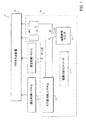
本発明の一実施形態は、発光ダイオード(LED)製造システム8(図1参照)のバブラー及びプロセス反応器に用いられる温度制御ユニットを含むことができる。システム8は、プロセス反応器10内のウェーハの温度を制御するウェーハ温度制御システム12と、プロセス反応器10と関連した真空チャンバ(図示せず)内のガス圧力を制御する真空支援システム14と、種々のガスを真空チャンバ内に導入するガス送り出しシステム16と、ガスを真空チャンバ内に導入する流量を制御する1つ又は2つ以上の質量流量コントローラ(MFC)18と、液体化合物を貯留し、この液体化合物を真空チャンバ内に送り出す任意適当な形式の少なくとも1つのバブラー19と、バブラー19内に貯留された液体化合物の温度を制御する温度制御ユニット20と、電力を温度制御ユニット20に供給し、この温度制御ユニットを制御する電源付きコントローラ17とを有するのが良い。システム8のガス送り出しシステム16、質量流量コントローラ18、バブラー19、温度制御ユニット20及びコントローラ17は、前駆物質送り出しシステム15と呼ばれる場合のあるサブシステムを形成する。
One embodiment of the present invention may include a temperature control unit used in a bubbler and process reactor of a light emitting diode (LED) manufacturing system 8 (see FIG. 1). The system 8 includes a wafer
一実施形態では、バブラー19は、例えば図6〜図13に示されているように、反応化合物を液体状態(液体化合物)で保持するガラス又は石英入れ物21と、入れ物の底部の近くまで下方に延びる入口管22と、入れ物の頂部の近くに設けられていて、バブラーをプロセス反応器10の真空チャンバ(図示せず)に流体結合する出口管23とを有する従来型バブラーであるのが良い。入口弁24が、入口管22に設けられ、出口弁26が、出口管23に設けられている。中央に配置されたサービス用継手27が、容器21の頂部内に延びるサービス用管28に結合されている。プロセス反応器10の動作中、キャリヤガスがガス送り出しシステム16からバブラー19の入口管22に供給される。キャリヤガスは、容器21内の液体化合物中で泡立って液体化合物を蒸発させ、このキャリヤガスは、蒸発した液体化合物と一緒になって出口管23を通って出て質量流量絞り装置(MFC)18を通ってプロセス反応器10の真空チャンバ内に入る。また、1つ又は2つ以上の他のMFC18を介して同一又は異なるガスのうち1種類又は2種類以上をガス送り出しシステム16からプロセス反応器に直接導入するのが良い。
In one embodiment, the
プロセス反応器10は、多数のバブラーを用いるのが良く、これらバブラーは各々、バブラー19と類似しているのが良く、互いに異なる液体化合物を収容するのが良い。プロセス反応器10及び前駆物質送り出しシステム15が図示されている図2に示すように、プロセス反応器10は、第1のバブラーB1、第2のバブラーB2及び第3のバブラーB3を用いるのが良く、これらバブラーは各々、ガス#1、ガス#2及びガス#3をそれぞれ受け入れるその入口管及びMFC18を介してプロセス反応器10に流体結合されたその出口管を有する。バブラーB1,B2,B3は各々、それぞれの第1、第2及び第3の抵抗型温度デバイスRTD1,RTD2,RTD3によってモニタされるその温度を有し、各バブラーの温度は、第1、第2及び第3の温度制御ユニット(図示せず)と関連したそれぞれの第1、第2及び第3の熱電子デバイスTE1,TE2,TE3によって制御される。熱電子デバイスTE1,TE2,TE3の制御を容易にするために電子ラック30が設けられ、この電子ラックは、ネットワークハブ32とそれぞれの第1、第2及び第3の熱電子デバイスTE1,TE2,TE3との間に結合された第1、第2及び第3の電源ユニットPS1,PS2,PS3を有している。ネットワークハブ32は、直接か又はコンピュータネットワークを介するかのいずれかでプロセス反応器10の制御インターフェイス(図示せず)及び(又は)コンピュータシステム34に結合されている。かくして、熱電子デバイスTE1,TE2,TE3及びバブラーB1,B2,B3の各々の温度は、反応器10の制御インターフェイス及び(又は)コンピュータシステム34により遠隔制御できる。
バブラー19及び電源ユニット38が図3に示されており、この電源ユニットは、電源ユニットPS1,PS2,PS3のうちの1つであるのが良い。加熱器52、少なくとも1つの熱電子デバイス54及び抵抗型温度デバイス(RTD)56が、バブラーの温度を制御したりモニタしたりするために設けられている。電源ユニット38は、電源ネットワーク58、DeviceNet(登録商標)リンク61を備えたディジタルコントローラ60、ソリッドステートリレー(SSR)62、スイッチ64、1つ又は2つ以上のヒューズ65及び外部電源に接続可能な電力端子66,67を有している。
A
DeviceNet(登録商標)リンク61により、ディジタルコントローラ60をDeviceNet(登録商標)ネットワーク(図示せず)を介してネットワークハブ32に接続でき、このDeviceNet(登録商標)ネットワークは、単純な工業用デバイス(例えば、コントローラ、センサ及びアクチュエータ)と高レベルデバイス(例えば、PLCコントローラ及びコンピュータ)との間の接続を可能にする標準型のオープン且つ低レベルネットワークである。DeviceNet(登録商標)ネットワークを介して、ディジタルコントローラ60は、プロセス反応器10及びコンピュータシステム34が結合されたコンピュータネットワークに結合され、このディジタルコンピュータは、コンピュータネットワーク中にそれ自体のアドレスを有し、したがって、ディジタルコントローラ60をプロセス反応器10の制御インターフェイス及び(又は)コンピュータシステム34からアドレス指定して制御できるようになっている。ディジタルコントローラ60は、電力端子66,67及び回路アースにそれぞれ接続可能な電力ポートL1,L2,Gと、電源ネットワーク58を制御する制御ポートC1,C2と、SSR62を制御する制御ポートC3,C4と、RTD56からの読みを受け入れるデータポートD1,D2,D3とを有している。
The DeviceNet® link 61 allows the digital controller 60 to be connected to the
電源ネットワーク58は、電力端子66,67及び回路アースにそれぞれ接続可能な電力ポートL1,L2,Gと、ディジタルコントローラ60の制御ポートC1,C2からそれぞれ制御信号を受け取る制御ポートC1′,C2′と、電力を熱電子デバイス54に供給する電力出力端子P+,P−とを有する。電力出力端子P+,P−から供給され、ディジタルコントローラ60から制御ポートC1′,C2′のところで受け取った制御信号に依存する電力を制御することにより、熱電子デバイス54がバブラー19から熱を奪い又は熱をバブラー19に与える速度を制御することができる。SSR62は、可動部品の無い状態で回路を電気的に閉じ又は中断するソリッドステートスイッチングデバイスであり、このSSRは、加熱器52と電力端子66,67のうちの一方との間に結合されていて、ディジタルコントローラ60の制御ポートC3,C4からの制御信号に基づいて、加熱器52を電力端子に接続し又は加熱器62を電力端子から切り離すよう構成されている。
The
液体化合物42を所望の温度でバブラー19内に維持するため、ディジタルコントローラ60は、RTD56からの温度の読みを受け取り、これに基づいて、熱電子デバイス54に供給される電力を調節し、かくして、デバイス54が所望の温度と温度の読みとの間の差の関数として熱をバブラー19から奪い又は熱をバブラー19に供給する速度を調節する。コントローラ60は又、RTD56からの温度の読みが所望の温度よりもかなり低い場合、加熱器52を或る期間にわたり作動させるようSSR62を動作させるためにも使用でき、この場合、加熱器52は、バブラー19内の液体化合物42の温度を所望の温度に至らせるのにより効率的である場合がある。
In order to maintain the liquid compound 42 in the
プロセス反応器10は、各々が半導体製造プロセスで用いられる互いに異なる液体化合物を収容する複数のバブラー19及び各々がそれぞれのバブラー19の温度を制御する複数の温度制御ユニット20を有するのが良く、かかるバブラー及び温度制御デバイスは、任意適当な形態で設けられる。例えば、前駆物質送り出しシステム15の一部分の平面図が、図4及び図5に示されており、この前駆物質送り出しシステム15は、6つのバブラー19及びバブラー19の温度をそれぞれ制御する6つの温度制御ユニット20を有している。バブラー19及び温度制御ユニット20は、ユーティリティハウジング88内に収納され、このユーティリティハウジングは、反応器ハウジングとは別個のものであって、プロセス反応器を点検整備する他のユーティリティ、例えば温度制御システム12及び真空支援システム14を収納した密閉環境である。図4及び図5に示す送り出しシステム15の一部分では、電源ユニットの電子ラック90が、好ましくは、温度制御ユニット20を遠隔制御するためにユーティリティハウジング又はエンクロージャ88の外部に配置されている。温度制御ユニット20を電源ユニットの電子ラック90に電気的に結合する電気ケーブル98が設けられている。図5は、図14に示されたシステム15の一部分の側面図であり、この場合、電子ラック90が、温度制御ユニット20の各々につき1つずつ設けられた6つの電源ユニット91〜96を有していることが示されている。しかしながら、理解されるように、複数の温度制御ユニット20を動作させるために単一の電源ユニットを設けても良いことは理解されよう。
The
図4及び図5の例示の形態では、温度制御ユニット20は、ユーティリティハウジング88内に互いに間隔を置いた線形形態で配置されている。温度制御ユニット20は各々、支持体又はプラットホーム99、例えばスタンド上に載るのが良く、このスタンドは、図6に示されているように、任意適当な手段、例えば複数のブラケット114によってベース112の上方に支持された高い位置にあるプラットホーム110を有するのが良い。温度制御ユニット20は各々、それぞれのバブラー19が浸漬された入れ物を有する。温度制御ユニット20は各々、人の手で温度制御ユニットを容易に掴めるように第1の取っ手116及び第2の取っ手118を更に有するのが良い。
In the exemplary configuration of FIGS. 4 and 5, the
本発明の温度制御ユニットは、任意適当な形態のものであって良い。図6〜図14に示す一実施形態では、温度制御ユニット20は、バブラー19を受け入れる入れ物、タンク又は容器120を有し、この温度制御ユニットは、タンク120内の液体の蒸発を無くさないまでも最小限に抑えるように取り外し可能なフランジ124でバブラー19の入れ物21をタンク内に収納している。タンク120は、任意適当な材料、例えばステンレス鋼、アルミニウム又は銅により任意適当な仕方で製造可能であり、このタンクは、内部キャビティ又はチャンバ128、開口した頂端部130、円筒形側壁132、チャンバ128内に大気圧を保つ通気穴133及び任意適当な手段、例えばボルト、ねじ又は他の締結具(図8及び図9参照)により側壁132の底端部に固定された全体として平らなベース134を有している。タンク120は、環状上側フランジ136及び環状フランジ138を更に有し、これらフランジ136,138は、任意適当な仕方で円筒形側壁132の上端部及び下端部にそれぞれ固定されている。例えば、円筒形側壁132の下端部は、下側環状フランジ138の内周部を受け入れる環状溝140を備え、この下側環状フランジの内周部は、かくして、円筒形側璧132とタンク120のベース134との間に捕捉される(図9参照)。これと同様に、円筒形側壁の上端部は、上側環状フランジ136(図13参照)の内周部を受け入れる環状溝142を備えている。タンク120及びそのチャンバ128は、現在入手できる大抵のバブラー19の入れ物21を受け入れるような寸法形状になっている。
The temperature control unit of the present invention may be of any suitable form. In one embodiment shown in FIGS. 6-14, the
取り外し可能なフランジ124は、温度制御ユニット20に用いられている特定のバブラー19に合った寸法形状のエンクロージャ部材、蓋又はカバーの一部である。例えば、図7〜図12に示すように、取り外し可能なフランジ124は、サイジングキット又は密封構造体143の一部であるのが良く、このサイジングキット又は密封構造体143は、取り外し可能なフランジ124、Oリング144及びクランプ146を有している。取り外し可能なフランジ124及びクランプ146は各々、適当な材料、好ましくは断熱材料、例えばプラスチックで作られるのが良く、Oリング144は、ゴム又は任意他の適当なエラストマー材料で作られるのが良い。バブラーをタンク内に密封する任意適当な構造体又は組立体を設けても良く、又、かかる任意の構造体又は組立体は、サイズ、形状及び寸法が互いに異なる複数のバブラーのうちの1つを収容するよう設計されると共に構成されていても良いことは理解されよう。
The
図6〜図14に示す実施形態では、密封構造体143の環状上側フランジは、タンク120の円筒形側壁132の上端部であるタンク120の上端部に、任意適当な手段、例えば、取り外し可能なフランジ124に設けられたボア150をそれぞれ貫通し、タンク120の側壁132の頂部に設けられたそれぞれのねじ山付きボア152内に螺入された複数の円周方向に設けられたボルト又は他の締結具148により固定されている。密封構造体143とタンク120との間の流体密シールを促進するためのオプションとして追加のOリング153を密封構造体143内に設けると共に取り外し可能なフランジ124とタンク120との間に配置するのが良い(図9参照)。タンク120の上側フランジ136の内周部は、取り外し可能なフランジ124とタンク120の円筒形側壁132の上端部との間に捕捉されるのが良い。取り外し可能なフランジ124は、中央開口部154を備え、バブラー19の入れ物21は、タンク120内に配置できるようこの中央開口部を通って挿入される(図13参照)。Oリング144は、バブラーの周りに配置されると共に例えばフランジ124の頂部に形成された環状溝の中に収納された状態で取り外し可能なフランジ124の頂部に嵌められている。この場合、環状クランプ146は、バブラー入れ物の頂部周りに位置決めされ、Oリング144及び取り外し可能なフランジ124に押し付けられている。
In the embodiment shown in FIGS. 6-14, the annular upper flange of the sealing
一実施形態では、クランプ146は、割りリング型クランプであり、これは、2つの半円形半部146a,146bで形成され、任意適当な手段、例えば、クランプに設けられたそれぞれのボア(図示せず)を貫通し、上側フランジに設けられたそれぞれのボア(図示せず)内に螺入される複数の円周方向に設けられたボルト又は他の締結具155によりフランジ124に取り外し可能に固定される(図12参照)。ボルト又はねじ155は、Oリング144を締め付け、取り外し可能なフランジ124とバブラー19の外周部との間の隙間を閉じる。クランプの各半部146a,146bの内側リムは、好ましくは、肩156を備え、この肩は、タンク120の内部のバブラー19の位置を固定する(図13参照)。他のサイズ、寸法及び形状のバブラー19が温度制御装置20のタンク120内に収納される場合、異なる密封構造体又はサイジングキット143を用いるのが良い。 密封構造体143は、バブラー入れ物21がタンク120内に配置されると、タンク120の内部キャビティ又はチャンバ128を密封するのに役立つ。適当な流体、好ましくは作業液、例えばフルオリナート(fluorinert)が、バブラーの周りでチャンバ128内に設けられるが、このようにするかどうかは任意である。タンク120の密封により、作業液の蒸発が阻止されると共に掛かる液体の温度の制御が容易になる。この点に関し、タンク120内の温度制御液体は、プロセス反応器110と関連したエレクトロニクスを含むバブラー19の外部の環境から隔離され、かかるエレクトロニクスは、水分、例えば作業液からの蒸発に起因して損傷を受ける場合がある。
In one embodiment, the
タンク120内の作業流体の温度は、任意適当な手段により制御可能である。一実施形態では、図8、図9、図13及び図14に示すように、温度制御ユニット20は、タンク120内の作業流体の温度を制御する少なくとも1つの熱交換器装置160を有するのが良い。複数の熱交換器装置160が設けられる場合、熱交換器装置は、好ましくは、タンクの円筒形側壁132周りにこれに沿って円周方向に間隔を置いた位置に配置される。熱交換器装置160は各々、1つ又は2つ以上の熱電子デバイス126及び熱電子デバイス162と並置して配置されていて、熱を熱電子デバイスから奪って冷却する熱交換器ハウジング164を有するのが良い。したがって、熱電子デバイス162は、タンク120と、タンク120を加熱し又は冷却し、かくしてこの中に入っている作業液を加熱し又は冷却する熱交換器装置160のそれぞれの熱交換器ハウジング164との間にサンドイッチされている。各熱交換器ハウジング164は、任意適当な材料、例えばステンレス鋼で作られ、2つの半部又はシェルから形成される。シェルは、各々、熱交換器内に入口166及び出口168により接近可能な内部チャンバを形成する内部凹部を備えており、この入口166及び出口168は、それぞれ、設備水入口及び設備水出口であるのが良い。熱電子デバイス162は、好ましくは、タンク120の外面と密な接触状態にある。
The temperature of the working fluid in the
温度制御ユニット20は、外側シェル又はハウジング170を更に有し、この外側シェル又はハウジングは、図6〜図14に示すようにタンク120及び熱交換器装置160を包囲するのが良い。一実施形態では、ハウジング170は、各々任意適当な材料、例えばステンレス鋼で作られた外側又は外部上側ハウジング172及び外側又は外部ベースハウジング174を有する。上側ハウジング172は、任意適当な手段、例えば複数の円周方向に配置されたねじ又は他の締結具によってタンク120の上側フランジ136に固定されている。上側フランジ172は又、下側フランジ138に螺着され又は違ったやり方で締結された複数の円周方向に配置されたブラケット176及び上側フランジ172をブラケット176に接合する複数のねじ又は他の締結具によって下側フランジ138に固定されている(図8、図9及び図13参照)。ベースハウジング174は、円筒形側壁及び実質的に平らな頂壁を備え、このベースハウジングは、任意適当な手段によってタンク120の下側フランジ138に固定されている。例えば、ベースハウジング174は、複数の円周方向に配置されたブラケット176にボルト止めされるのが良い。
The
ベースハウジングは、その下端部又は底部が開口しているのが良く、温度制御ユニットは、ベースハウジング174を貫通していて、適当な流体、例えば設備水を熱交換器装置160に提供し又はこれから設備水を取り出すためにハウジング170の外部から接近可能な入口及び出口コネクタ180,182を更に有している。かかるコネクタ180,182は、図8〜図13に示すように、ベースハウジング174の内部に接近可能な部分を有し、この部分は、任意適当な導管、例えば分かりやすくするために図面のどれにも示されていない管類によって熱交換器160のそれぞれの入口及び出口に連結されている。
The base housing may be open at its lower end or bottom, and the temperature control unit may pass through the
タンク120内のフルオリナート又は他の作業液は、作業液の温度を所望のレベルに維持しやすくするために例えばポンプ184により温度制御ユニット20を通って再循環される。一実施形態では、図9及び図13に示すように、ポンプ184は、タンク120のベース134の中央部分に取り付けられていて、タンク120の下側フランジ138に設けられた中央開口部を通って下方に延びている。入口ボア又はポート160が、タンクベースに設けられていて、ポンプ184の入口に通じている。加うるに、出口ボア又はポート187が、タンクベースに設けられていて、一端部がポンプ184の出口に通じると共に他端部が再循環入口ボア188に通じており、この再循環入口ボアは、タンクの円筒形側壁132を長手方向に貫通してタンク120の内部チャンバ128に通じる開口部190まで延びている(図9及び図13参照)。開口部190が、円筒形側壁132の頂部の近くに設けられている。
Fluorinate or other working fluid in
流体をタンク120内に充填し又はタンク120内の流体を排出する充填部又は排出部192も又設けるのが良い。この流体カプラ又はコネクタ192は、ハウジングのベース部分を貫通しており、タンク内に用いられる作業液の入口ポート又は充填部及び出口ポート又は排出部として役立つ。流体カプラ又はコネクタ192は、任意適当な手段、例えば管類によりポンプグランド(図示せず)に流体結合されている。カップ状ハウジング194が、ポンプの下方部分に沿って上方に延び、この下方部分は、タンク120の下側フランジ138の下に延びるポンプの部分であり、カップ状ハウジング194は、任意適当な手段、例えば複数のねじ又は他の締結具によって下側フランジ138に固定されている。
A filling or draining
1つ又は2つ以上の温度センサ(図示せず)を温度制御装置又はユニット20内、例えば、熱交換器装置160のうちの1つ又は2つ以上の中、タンク120の中、バブラー19の中又は上述の要素の組合せの中に設けて、フルオリナート又は他の作業液、バブラー19内の物質の温度及び温度制御装置20内の任意他の温度をモニタすると共にフィードバックをコントローラ60に提供するようになっているのが良い。かかる温度センサのうちの少なくとも1つは、好ましくは、タンク内のフルオリナート又は他の作業液の温度をモニタするためにタンク120の円筒形側壁132内に設けられる。
One or more temperature sensors (not shown) are connected in the temperature control device or
図10及び図11に最も明確に示された電気コネクタ196が、温度制御ユニット20とコントローラ60との間の電気的連絡を可能にするためにハウジング170のベース部分174を貫通している。電気コネクタ196は、任意適当な手段、例えば電線又はフレキシブル回路(図示せず)により熱電子デバイス162及び温度制御ユニット20のポンプ184に接続されている。任意適当な手段、例えば図4及び図5に示す電気ケーブルによってコネクタ196とコントローラ60を互いに連絡させることが可能である。コントローラ60は、例えば、熱交換器装置160内の熱電子デバイス162への電力の量及びその極性並びに再循環ポンプ184の作動を制御することができる。
The
温度制御ユニット20をスタンド99又は他の支持面上に支持する複数の脚部197が、温度制御ユニット20の下面に取り付けられている。脚部197は、温度制御ユニット20を支持面に対して水平を取るために個々に調節可能である。
A plurality of
作動及び使用にあたり、加熱作用又は冷却作用をタンク120に与えてこの中に入っている作業液及びかくしてバブラー入れ物21内に入っている物質を加熱し又は冷却することが望ましい場合、適当な極性のエネルギーを熱電子デバイス162に与える。例えばバブラー19内の物質の冷却が望ましい場合、タンク120に係合している熱電子デバイスの表面は、冷却作用をタンクに及ぼすのに役立つ。熱交換器160に係合している側部である熱電子デバイス162の反対側の側部により生じる熱は、熱交換器を通って流れる設備水によって吸収され、そして温度制御装置20から除去される。
In operation and use, if it is desired to apply heating or cooling to the
例えば管類をポンプ184の出口からタンク120の頂部まで引き回すのとは異なり、長手方向ボア188をタンク120の円筒形側壁132に設けることにより、温度制御ユニット20の設計が単純化される。長手方向ボア188は、好ましくは、タンク120の外部に取り付けられた熱交換器装置160のうちの1つの熱電子デバイス162の下に延びている。したがって、ボア188は、追加的に、作業液をユニット20の熱交換器装置160に密に連絡させることにより作業液の加熱作用又は冷却作用を増大させるのに役立つ。理解されるように、作業液をタンクに戻すための複数の長手方向ボア188をタンク120の円筒形側壁132に設けるのが良い。例えば、長手方向ボアは、作業流体の加熱効率又は冷却効率を一段と高めるために熱交換器装置160の各々の下に延びるのが良い。
Unlike, for example, routing tubing from the outlet of the
コントローラ91〜96をユーティリティハウジング88の外部に且つ温度制御ユニット20から遠ざけて配置することにより、コントローラ内のエレクトロニクスが密閉ハウジング又はエンクロージャ88内のガスによる損傷を受ける恐れが減少する。加うるに、温度制御ユニット20内における各バブラー19の密封及びバブラー内への温度制御ユニットの作業液の密封により、ユーティリティハウジング88内又はどこか他の場所への作業液の蒸発又は他の逃げ込みが最小限に抑えられ、かくして、逃げ出た作業液からのユーティリティハウジング88の内部の他のコントローラ、エレクトロニクス又は敏感な計器類の損傷の恐れが減少する。上述したことに加えて、温度制御ユニット内の作業液の密封により、作業液の望ましくない蒸発が無くならないまでも最小限に抑えられ、かくして、反応器システム又はその部分部分が作業液を補充するために作動停止しなければならない頻度が減少する。
By placing the controllers 91-96 outside the
本発明の温度制御ユニットの他の実施形態を提供できる。例えば、温度制御ユニットは、一体形膨張タンクを備えることができ、この一体形膨張タンクは、タンクの内部チャンバ内における作業液の適正な又は所望のレベルの維持を容易にするためのものである。一体形膨張タンクを有する温度制御ユニット201の一実施形態が、図15に示されている。温度制御ユニット又は装置201は、温度制御ユニット20と実質的に同一であり、ユニット20,201の同一のコンポーネントを説明するのに同一の参照符号が用いられている。任意適当な膨張タンクを設けても良いが、温度制御ユニット201内の膨張タンク202は、タンク120の内部チャンバ128のうちの幾つか又は全てを包囲するチャンバ203から成る。より好ましくは、膨張タンクは、断面が環状の円筒形チャンバであり、この円筒形チャンバは、タンク102の円筒形側壁132内に形成されると共にタンク120の内部チャンバ128周りに同心状に配置される。1つ又は2つ以上の入口ポート204(かかるポートの1つが、図15に示されている)が、タンク120の内部チャンバ128を膨張タンクのチャンバ203に流体結合していて、好ましくは、膨張タンクの頂部の近くに設けられている。
Other embodiments of the temperature control unit of the present invention can be provided. For example, the temperature control unit may comprise an integral expansion tank that facilitates maintaining an appropriate or desired level of working fluid within the interior chamber of the tank. . One embodiment of a
温度制御ユニット201内のポンプの流れは、温度制御ユニット20内のポンプの流れとは逆である。この点に関し、ポート又は通路(図示せず)が、構造が温度制御ユニット20の出口ポート187に類似していて、タンク120の平らなベース134に形成されると共にポンプ184の入口に結合された入口通路208に流体連結している。構造が温度制御ユニット20の入口ポート186に類似した出口ポート209が、タンク120の底部に設けられていて、ポンプ184の出口に流体結合されている。したがって、フルオリナート又は他の作業液は、内部チャンバ128からオーバーフローして膨張タンク202の1つ又は2つ以上の入口ポート204によって膨張タンク202のチャンバ203内に流れる。次に、膨張タンク202内のフルオリナート又は他の作業液は、ポンプ184を通り、そしてタンク120の底部に設けられた出口ポート209を通ってタンクの内部チャンバ128に再び入る。
The pump flow in the
作動及び使用にあたり、タンク120内のフルオリナート又は他の作業液をタンクの内部チャンバ128の頂部の近くの高さ位置に維持してバブラー入れ物21の実質的に全てを包囲すると共にバブラー内の物質の温度を良好に調節することが有利である。膨張タンクは、温度制御ユニットのフットプリント及びサイズを最小限に抑えるよう温度制御ユニットのコンパクトな境界部内に設けるのが有利である。
In operation and use, the fluorinate or other working fluid in the
ソリッドステート温度制御装置20,201に関する初期仕様は、動作温度が−20℃〜+60℃であって精度が±0.1℃の温度をもたらすことができる状態で、20℃で100ワットの冷却能力及び20℃で100ワットの加熱能力を提供する。毎分0.5ガロン(1.89リットル)の水の流量を提供するのが良く、温度制御ユニット20,201は各々、好ましくは、平均故障間隔、即ちMTBFが、30,000時間以上である。
Initial specifications for solid
本発明の温度制御装置の他の実施形態を提供できる。前駆物質送り出しシステム15の一部分である図16のシステム221は、反応器ハウジング222を有し、この反応器ハウジングは、この反応器ハウジング内に設けられると共に任意適当な形態に配置された複数のバブラーのそれぞれの温度を制御する複数の任意適当な温度制御ユニットを有している。任意適当なバブラー、例えばバブラー19をシステム221に用いることができる。好ましい一実施形態では、バブラー19は各々、半導体製造プロセスに用いられる互いに異なる物質を収容し、温度制御ユニットは各々、液体を用いない温度制御ユニット又はチラー223である。チラー223からの物質の流れは、半導体製造設備の反応器ハウジング又はエンクロージャ222内に設けられたエレクトロニクス(図示せず)から制御される。3つの液体を用いない温度制御ユニット223の部分部分が、エレクトロニクスエンクロージャ222内に互いに間隔を置いた線形形態で示されている。温度制御ユニット223は各々、例えば電気ケーブル224により温度制御装置223から見て遠くに且つ好ましくはハウジング又はエンクロージャ222の外部に設けられたそれぞれのコントローラ226に電気的に結合されている。かかる遠隔コントローラ226を適当なエンクロージャ、例えば可動ラック227内に設けるのが良い。コントローラは各々、電源及びそれぞれの温度制御ユニットの作動を制御する必要なエレクトロニクスを有する。理解されるように、複数の温度制御ユニットを作動させる単一のコントローラを設けることができ、例えば、1つのコントローラが、システムの温度制御ユニットのうちの2つ、3つ、4つ、5つ又はそれどころか全てを作動させることができる。
Other embodiments of the temperature control device of the present invention can be provided. The
チラー223は各々、バブラー19を受け入れるタンク236又は他の入れ物を有している。好ましい一実施形態では、タンク236は、内部チャンバ237及び開口した頂端部238を有し、このタンクは、任意適当な材料、例えばステンレス鋼、アルミニウム又は銅で作られ、好ましくはアルミニウムで作られる。タンクは、任意適当な仕方で形成でき、組み立て状態では図20に示されているように、円筒形側璧241及び任意適当な手段、例えばボルト、ねじ又は他の締結具243により側壁241の下端部に固定された全体として平らなプレート組立体242を有する。側壁241の外面244は、側壁の外部及びかくしてタンクの外部からの伝熱具合を向上させるよう波形になっており、スクラップ状になっており、又は違ったやり方で形成されるのが良い。タンク236及びそのチャンバ237は、現在入手できる大抵のバブラー19を受け入れるような寸法形状のものである。
Each
プレート組立体242は、好ましくは、平面図で見て円形であり、第1の又は上部隔離プレート246及び第2の又は底部プレート247で形成されている。1つ又は2つ以上の温度変更装置、例えば1つ又は2つ以上の熱電子デバイス248が、プレート組立体242の内部に設けられ、第1のプレート246と第2のプレート247との間にサンドイッチされている。底部プレート又はヒートシンク247は、任意適当な材料、例えばステンレス鋼、アルミニウム又は銅で作られ、好ましくはアルミニウムで作られており、この底部プレート又はヒートシンクは、任意適当な手段、例えば複数のボルト、ねじ又は他の締結具243によりタンクの円筒形側壁に固定されている。好ましい一実施形態では、複数の円周方向に設けられた締結具243が、円筒形側壁241の底面に設けられたねじ山付きボアに螺入するために底部プレート247に設けられたそれぞれのボアを貫通して上方に延びている。隔離プレートは、任意適当な材料、例えばステンレス鋼、アルミニウム又は銅で作られ、好ましくはアルミニウムで作られ、この隔離プレートは、任意適当な手段、例えば複数のボルト、ねじ又は他の締結具248によりヒートシンク247に固定されている。具体的に言えば、複数の、即ち5つの締結具248が、底部プレート247に設けられたねじ山付きボアに螺入するために隔離プレート246に設けられたそれぞれのボアを下方に貫通して延びている。
The
好ましくは、隔離プレート246とタンクの円筒形側壁241との間に流体密シールを形成するために、Oリング251又は他の適当な密封構造体が、隔離プレートと側壁との間に設けられている。この点に関し、隔離プレート246は、側壁241の下端部内に嵌まり、隔離プレートの環状外面の周りにこれに沿って延びる環状溝252が設けられている。ゴム又は任意他の適当なエラストマー材料で作られたOリング251は、かかる溝252内に嵌め込まれた状態で隔離プレート246の環状外面と側壁241の環状内面の両方に流体的に係合している。このようにOリング251を隔離プレート246と円筒形側壁241の両方に流体的に係合させることにより、円筒形側壁及び隔離プレートは、チラー223内の物質のための補助格納容器として役立ち得る。Oリングは、更に、隔離プレート246を円筒形側壁241から断熱するのに役立つ。さらに、この点に関し、空隙が、隔離プレートの外周部と円筒形側壁の内部との間に設けられていて、これら部材相互間の断熱を促進するようになっている。
Preferably, an O-
1つ又は2つ以上の熱電子デバイス253又は他の適当な温度変更装置が、隔離プレート246と底部プレート247との間に設けられている(図18〜図20参照)。
One or more
バブラー19の底面に係合し、かくして、バブラーと隔離プレート246との間の熱伝導性及び伝熱具合を促進する任意適当な熱伝送性材料256、例えばプラスチックの層が、隔離プレート246の頂部に設けられている。加熱器257が、好ましくは、バブラー入れ物21の外面の少なくとも一部分に係合して、望ましい場合には熱をバブラー19及びこの中に入れられている物質に提供するようになっている。任意適当な加熱器を用いることができるが、好ましい一実施形態では、加熱器257は、バブラー入れ物21の管状側壁に沿ってぐるりと円周方向に延びるシリコン電気加熱器である。チラー223の円筒形側壁241は、加熱器257の外面にぴったりと係合するような直径方向寸法になっている。このように、加熱器257は、バブラー19と円筒形側壁241との間にサンドイッチされている(図19及び図20参照)。
A layer of any suitable
温度制御ユニット又はチラー223は、ユニット内に用いられている特定のバブラーに合った寸法形状の蓋又はカバーを有するのが良い。例えば、図17〜図20に示すように、温度制御ユニット223は、任意適当な材料、好ましくは、断熱材料、例えばプラスチックで作られていて、バブラー19をタンク236内に固定するエンクロージャ部材、例えばクランプ261を備えている。理解されるように、バブラーをタンク内に固定し、場合によっては密封するための任意適当な構造、エンクロージャ部材又は組立体を設けるのが良く、又、かかる任意の構造体又は組立体を、サイズ、寸法及び形状の異なる複数のバブラーに対応するよう設計すると共に構成するのが良い。例示の実施形態では、取り外し可能な環状クランプ261は、バブラー入れ物21の頂部の周りに設けられた状態でバブラー入れ物に圧接されている。割りリング型クランプ261(これは、2つの半円形半部261で作られたリングであり、これらクランプ半部のうちの1つが図19及び図20に示されている)が、任意適当な手段、例えば、クランプ261に設けられたボアをそれぞれ貫通し、円筒形側壁241に設けられたボアにそれぞれ螺合された複数の円周方向に設けられたボルト、ねじ又は他の締結具によってタンクの円筒形側壁の頂部に取り外し可能に固定されている。クランプ261の各半部262の内側リムは、好ましくは、肩264を備え、この肩は、タンク263の内部におけるバブラー19の位置を固定する。Oリング又は任意他の適当な密封構造体(図示せず)をクランプ261とチラー223の円筒形側壁241との間に、更に、タンク内のバブラーを密封することが望ましい場合には、クランプ261とバブラー19との間に設けるのが良い。
The temperature control unit or
温度制御装置223の外部から電気加熱器257及び熱電子デバイス253との電気的接続を可能にする電気コネクタ(図示せず)が設けられている。電気コネクタは、任意適当な手段、例えば電線又はフレキシブル回路(図示せず)によって加熱器257及び熱電子デバイス253に接続されている。任意適当な手段、例えば電気ケーブル224によって電気コネクタとコントローラ60を互いに連絡させることが可能である。コントローラは、例えば、加熱器257への電力の量並びに熱電子デバイス253への電力の量及びその極性を制御することができる。
An electrical connector (not shown) that enables electrical connection with the
バブラー19内の物質の温度は、システム221内に設けられた任意適当な手段により制御できる。この点に関し、例えば、加熱器257は、バブラーの入れ物21及びかくして必要ならばこの中に入っている物質の温度を増加させるのに役立つ。熱電子デバイス253は、冷却作用バブラー入れ物21及びこの中の物質に与えるのに役立つ。具体的に説明すると、熱電子デバイスは、直接的な冷却作用を隔離プレート246に及ぼし、この隔離プレートは、かかる冷却作用をバブラー入れ物21及びこの中の物質に伝達する。熱伝導性材料256の層は、隔離プレートからバブラー入れ物への冷却作用の伝達具合を増大させるのに役立つ。熱電子デバイス253の逆の側部により生じる熱は、ヒートシンクとして働く底部プレート247により吸収される。底部プレートからの熱は、タンク236の円筒形側壁241により吸収され、タンクの波形外面は、かかる熱を大気中に消散させやすくする。理解されるように、熱電子デバイス253は又、熱をバブラー入れ物21に与えるのにも利用できる。
The temperature of the material in the
1つ又は2つ以上の温度センサ(図示せず)を温度制御装置223内、例えば、タンク236の中、バブラー19の中、隔離プレート246と底部プレート247との間又は上述の要素の組合せの中に設けて、バブラー19内の物質の温度及び温度制御装置223内の任意他の温度をモニタすると共にフィードバックをコントローラ60に提供するようになっているのが良い。
One or more temperature sensors (not shown) are connected in the
ソリッドステート温度制御装置223に関する初期仕様は、動作温度が−20℃〜+90℃であり、精度±0.1℃の温度をもたらすことができる状態において、20℃で100ワットの冷却能力及び20℃で100ワットの加熱能力を提供する。毎分0.5ガロン(1.89リットル)の水量を提供するのが良く、温度制御ユニット223は、好ましくは、平均故障間隔、即ちMTBFが、30,000時間以上である。
Initial specifications for the solid
温度制御装置223は、これが熱電子デバイス253を冷却し又は加熱するようタンク236を通過する液体、例えばフルオリナート、設備水又は他の液体を収容していないので有利である。液体が入っていないことは、温度制御装置内に液体が入っていることによりプロセス反応器システムのエレクトロニクス又は他のコンポーネントが損なわれるという懸念がある場合に有利である。熱電子デバイス253とは別体である加熱器257を設けることは、例えば、この加熱器が熱電子デバイスよりも多くの熱をもたらすよう構成でき、又、熱電子デバイスが冷却作用と加熱作用の両方をもたらすために酷使される装置と比較して、加熱器が、冷却と加熱との間の迅速な応答時間をもたらすことができるので、有利な場合がある。温度制御装置223は、バブラー19内からシステム221内への物質の漏れを阻止するよう保護する補助格納容器、即ち、タンク236を有している。
The
Claims (15)
前記容器とは別体であり、前記バブラーを通すことができる開口部を有する密封構造体であって、前記内部チャンバ内の液体を封止し、前記バブラーの前記入れ物の前記側壁の上端と前記容器との間で延びる前記密封構造体と、を備え、
当該密封構造体は、前記入れ物と係合して湿気バリアを形成して内部チャンバからの前記液体の蒸発を抑制するための弾性部材を備え、
さらに、前記温度制御装置は、
前記容器に結合されていて、前記内部チャンバに加熱作用又は冷却作用を与える温度変更装置とを有することを特徴とする温度制御装置。 A temperature control device for use in a process reactor system equipped with a liquid and a bubbler with a container provided with a side wall with an upper end , the container being arranged in the liquid up to the upper end of the side wall and liquid-tight container with an internal chamber that can Rukoto receiving the container and the liquid in the bubbler,
The said container is a separate body, a sealing structure having an opening which can be passed through the bubbler, sealing the liquid within said internal chamber, said upper end of the side wall of the container of the bubbler and a said sealing structure extending between the container,
The sealing structure includes an elastic member for engaging with the container to form a moisture barrier to suppress evaporation of the liquid from the internal chamber,
Furthermore, the temperature control device includes:
A temperature control device coupled to the container and having a temperature changing device for applying a heating action or a cooling action to the internal chamber.
内部チャンバ内の液体を循環させ、前記膨張タンクに入れるために前記第2ポートに連結されたポンプを備える循環システムと、有し、
前記温度変更装置は、前記膨張タンクに結合されていて、前記膨張タンク内の前記液体に加熱作用又は冷却作用を与え、
前記循環システムは、前記膨張タンクから前記内部チャンバに液体を循環させることによって前記内部チャンバ内の前記液体の温度の制御を容易にする、請求項1記載の温度制御装置。 The container includes an upper portion formed with a first port; a bottom portion formed with a second port; an expansion tank disposed at least partially around the container and in communication with the internal chamber;
A circulation system comprising a pump connected to the second port for circulating liquid in an internal chamber and entering the expansion tank;
The temperature changing device is coupled to the expansion tank, and applies a heating action or a cooling action to the liquid in the expansion tank,
The circulation system, to facilitate control of temperature of the liquid in the inner chamber by circulating the liquid to the interior chamber from the expansion tank, the temperature control device according to claim 1.
Applications Claiming Priority (5)
| Application Number | Priority Date | Filing Date | Title |
|---|---|---|---|
| US66307205P | 2005-03-17 | 2005-03-17 | |
| US66300005P | 2005-03-17 | 2005-03-17 | |
| US60/663,072 | 2005-03-17 | ||
| US60/663,000 | 2005-03-17 | ||
| PCT/US2006/010037 WO2006099619A2 (en) | 2005-03-17 | 2006-03-17 | Temperature control unit for bubblers |
Publications (3)
| Publication Number | Publication Date |
|---|---|
| JP2008533746A JP2008533746A (en) | 2008-08-21 |
| JP2008533746A5 JP2008533746A5 (en) | 2009-05-07 |
| JP5156621B2 true JP5156621B2 (en) | 2013-03-06 |
Family
ID=36992481
Family Applications (1)
| Application Number | Title | Priority Date | Filing Date |
|---|---|---|---|
| JP2008502141A Expired - Fee Related JP5156621B2 (en) | 2005-03-17 | 2006-03-17 | Temperature control device for bubbler |
Country Status (5)
| Country | Link |
|---|---|
| US (1) | US8118939B2 (en) |
| EP (1) | EP1866458A4 (en) |
| JP (1) | JP5156621B2 (en) |
| TW (1) | TWI431449B (en) |
| WO (1) | WO2006099619A2 (en) |
Families Citing this family (11)
| Publication number | Priority date | Publication date | Assignee | Title |
|---|---|---|---|---|
| GB2432371B (en) * | 2005-11-17 | 2011-06-15 | Epichem Ltd | Improved bubbler for the transportation of substances by a carrier gas |
| US20080018004A1 (en) * | 2006-06-09 | 2008-01-24 | Air Products And Chemicals, Inc. | High Flow GaCl3 Delivery |
| US8568529B2 (en) * | 2009-04-10 | 2013-10-29 | Applied Materials, Inc. | HVPE chamber hardware |
| KR101765734B1 (en) | 2009-11-02 | 2017-08-07 | 시그마-알드리치 컴퍼니., 엘엘씨 | Solid precursor delivery assemblies and related methods |
| WO2011064610A2 (en) * | 2009-11-30 | 2011-06-03 | Szentivanyi Peter | Method and apparatus for handling gases |
| CN102467136B (en) * | 2010-10-31 | 2015-03-25 | 扬州百思德新材料有限公司 | Reaction kettle temperature control device |
| DE102012015045A1 (en) | 2012-07-31 | 2014-02-06 | Dockweiler Ag | Device for tempering a vessel in a chamber |
| US20150053375A1 (en) * | 2013-08-20 | 2015-02-26 | Noah Precision, Llc | Multi-loop temperature control system for a semiconductor manufacture process |
| JP6094513B2 (en) * | 2014-02-28 | 2017-03-15 | 東京エレクトロン株式会社 | Processing gas generator, processing gas generation method, substrate processing method, and storage medium |
| EP3786321A3 (en) * | 2019-08-27 | 2021-03-17 | Albert-Ludwigs-Universität Freiburg | Method and device for forming a coating and substrate comprising same |
| US11561032B2 (en) | 2019-11-12 | 2023-01-24 | Heat X, LLC | Magnetic induction water heater/chiller with separate heating/chilling zones |
Family Cites Families (23)
| Publication number | Priority date | Publication date | Assignee | Title |
|---|---|---|---|---|
| US3470902A (en) * | 1967-03-01 | 1969-10-07 | Atomic Energy Commission | Liquid flow control device |
| US4269057A (en) * | 1979-10-24 | 1981-05-26 | The United States Of America As Represented By The Secretary Of The Army | Multipurpose humidity controlled agent generator |
| US4441925A (en) * | 1981-04-04 | 1984-04-10 | Hiroshi Ishizuka | Method and an apparatus for producing titanium metal from titanium tetrachloride |
| JPS5995170U (en) * | 1982-12-17 | 1984-06-28 | 富士通株式会社 | chemical vapor deposition equipment |
| JPS62104022A (en) * | 1985-10-30 | 1987-05-14 | Seiko Epson Corp | Raw liquid vaporizer |
| US4612772A (en) * | 1985-11-04 | 1986-09-23 | Jones David E | Thermo-electric temperature controller for liquid chemical bubbler containers |
| US4911101A (en) * | 1988-07-20 | 1990-03-27 | General Electric Company | Metal organic molecular beam epitaxy (MOMBE) apparatus |
| JPH0760258B2 (en) * | 1988-09-28 | 1995-06-28 | 富士写真フイルム株式会社 | Processing method of silver halide color photographic light-sensitive material |
| DE58906491D1 (en) * | 1988-10-21 | 1994-02-03 | Buechi Lab Tech | Rotary evaporator. |
| JPH0644098Y2 (en) * | 1989-02-27 | 1994-11-14 | 黒谷 信子 | Bubbler for cleaning semiconductor wafers |
| JPH0697081A (en) * | 1992-09-10 | 1994-04-08 | Fujitsu Ltd | Vapor growth apparatus |
| JP2791424B2 (en) * | 1993-03-19 | 1998-08-27 | 工業技術院長 | Semiconductor processing equipment |
| TW359943B (en) * | 1994-07-18 | 1999-06-01 | Silicon Valley Group Thermal | Single body injector and method for delivering gases to a surface |
| US5968379A (en) * | 1995-07-14 | 1999-10-19 | Applied Materials, Inc. | High temperature ceramic heater assembly with RF capability and related methods |
| JPH10130845A (en) * | 1996-10-29 | 1998-05-19 | Mitsubishi Heavy Ind Ltd | Vapor generating device for chemical vapor deposition |
| JP2948791B2 (en) * | 1998-01-22 | 1999-09-13 | アプライド マテリアルズ インコーポレイテッド | How to change the liquid storage container |
| FI118805B (en) | 2000-05-15 | 2008-03-31 | Asm Int | A method and configuration for introducing a gas phase reactant into a reaction chamber |
| US6561498B2 (en) * | 2001-04-09 | 2003-05-13 | Lorex Industries, Inc. | Bubbler for use in vapor generation systems |
| TW539822B (en) * | 2001-07-03 | 2003-07-01 | Asm Inc | Source chemical container assembly |
| US6790475B2 (en) * | 2002-04-09 | 2004-09-14 | Wafermasters Inc. | Source gas delivery |
| US7077388B2 (en) * | 2002-07-19 | 2006-07-18 | Asm America, Inc. | Bubbler for substrate processing |
| JP2004327534A (en) * | 2003-04-22 | 2004-11-18 | Nec Kansai Ltd | Organic metal material vapor phase epitaxy device |
| KR20050004379A (en) * | 2003-07-02 | 2005-01-12 | 삼성전자주식회사 | Gas supplying apparatus for atomic layer deposition |
-
2006
- 2006-03-17 WO PCT/US2006/010037 patent/WO2006099619A2/en active Application Filing
- 2006-03-17 TW TW095109180A patent/TWI431449B/en not_active IP Right Cessation
- 2006-03-17 EP EP06738999A patent/EP1866458A4/en not_active Withdrawn
- 2006-03-17 US US11/378,664 patent/US8118939B2/en not_active Expired - Fee Related
- 2006-03-17 JP JP2008502141A patent/JP5156621B2/en not_active Expired - Fee Related
Also Published As
| Publication number | Publication date |
|---|---|
| WO2006099619A9 (en) | 2006-11-23 |
| US8118939B2 (en) | 2012-02-21 |
| WO2006099619A2 (en) | 2006-09-21 |
| EP1866458A4 (en) | 2010-10-20 |
| TWI431449B (en) | 2014-03-21 |
| JP2008533746A (en) | 2008-08-21 |
| US20060213446A1 (en) | 2006-09-28 |
| WO2006099619A3 (en) | 2007-08-30 |
| EP1866458A2 (en) | 2007-12-19 |
| TW200707150A (en) | 2007-02-16 |
Similar Documents
| Publication | Publication Date | Title |
|---|---|---|
| JP5156621B2 (en) | Temperature control device for bubbler | |
| JP5752238B2 (en) | Apparatus for radially distributing gas to a chamber and method of use thereof | |
| KR102517907B1 (en) | Precursor control system and process | |
| US5365960A (en) | Megasonic transducer assembly | |
| US11102912B2 (en) | Liquid immersion cooling platform | |
| KR101656333B1 (en) | Hydrophobicizing apparatus, hydrophobicizing method and storage medium | |
| US5054107A (en) | Radiating lamp fluid heating system | |
| CN101536148A (en) | Apparatus and methods for managing the temperature of a substrate in a high vacuum processing system | |
| CN210199007U (en) | Pool boiling heat transfer testing device | |
| US5613364A (en) | Compact replaceable temperature control module | |
| JPH0882402A (en) | Method and equipment for minimizing stagnation of liquid andgenerating dried steam | |
| KR101700494B1 (en) | Compact ampoule thermal management system | |
| US20020100282A1 (en) | Thermal exchanger for a wafer chuck | |
| US20030116180A1 (en) | Fluid heating system for processing semiconductor materials | |
| JP2022504947A (en) | Load lock body part, load lock device, and its manufacturing method | |
| JP4037466B2 (en) | Compact replaceable temperature control module | |
| KR101342991B1 (en) | Plasma etching apparatus and system for processing a substrate including the same | |
| JP2010053907A (en) | Fluid supply system heating device | |
| JPH06331214A (en) | Liquid heating method and device thereof | |
| JPH10206040A (en) | Heater |
Legal Events
| Date | Code | Title | Description |
|---|---|---|---|
| A521 | Request for written amendment filed |
Free format text: JAPANESE INTERMEDIATE CODE: A523 Effective date: 20090317 |
|
| A621 | Written request for application examination |
Free format text: JAPANESE INTERMEDIATE CODE: A621 Effective date: 20090317 |
|
| A977 | Report on retrieval |
Free format text: JAPANESE INTERMEDIATE CODE: A971007 Effective date: 20090708 |
|
| A131 | Notification of reasons for refusal |
Free format text: JAPANESE INTERMEDIATE CODE: A131 Effective date: 20110404 |
|
| A601 | Written request for extension of time |
Free format text: JAPANESE INTERMEDIATE CODE: A601 Effective date: 20110704 |
|
| A602 | Written permission of extension of time |
Free format text: JAPANESE INTERMEDIATE CODE: A602 Effective date: 20110711 |
|
| A521 | Request for written amendment filed |
Free format text: JAPANESE INTERMEDIATE CODE: A523 Effective date: 20111004 |
|
| A131 | Notification of reasons for refusal |
Free format text: JAPANESE INTERMEDIATE CODE: A131 Effective date: 20120423 |
|
| A601 | Written request for extension of time |
Free format text: JAPANESE INTERMEDIATE CODE: A601 Effective date: 20120723 |
|
| A602 | Written permission of extension of time |
Free format text: JAPANESE INTERMEDIATE CODE: A602 Effective date: 20120730 |
|
| A521 | Request for written amendment filed |
Free format text: JAPANESE INTERMEDIATE CODE: A523 Effective date: 20121023 |
|
| TRDD | Decision of grant or rejection written | ||
| A01 | Written decision to grant a patent or to grant a registration (utility model) |
Free format text: JAPANESE INTERMEDIATE CODE: A01 Effective date: 20121126 |
|
| A61 | First payment of annual fees (during grant procedure) |
Free format text: JAPANESE INTERMEDIATE CODE: A61 Effective date: 20121210 |
|
| FPAY | Renewal fee payment (event date is renewal date of database) |
Free format text: PAYMENT UNTIL: 20151214 Year of fee payment: 3 |
|
| R150 | Certificate of patent or registration of utility model |
Ref document number: 5156621 Country of ref document: JP Free format text: JAPANESE INTERMEDIATE CODE: R150 Free format text: JAPANESE INTERMEDIATE CODE: R150 |
|
| R250 | Receipt of annual fees |
Free format text: JAPANESE INTERMEDIATE CODE: R250 |
|
| R250 | Receipt of annual fees |
Free format text: JAPANESE INTERMEDIATE CODE: R250 |
|
| R250 | Receipt of annual fees |
Free format text: JAPANESE INTERMEDIATE CODE: R250 |
|
| R250 | Receipt of annual fees |
Free format text: JAPANESE INTERMEDIATE CODE: R250 |
|
| R250 | Receipt of annual fees |
Free format text: JAPANESE INTERMEDIATE CODE: R250 |
|
| R250 | Receipt of annual fees |
Free format text: JAPANESE INTERMEDIATE CODE: R250 |
|
| R250 | Receipt of annual fees |
Free format text: JAPANESE INTERMEDIATE CODE: R250 |
|
| LAPS | Cancellation because of no payment of annual fees |