JP5156302B2 - General-purpose hydraulic tool operation unit - Google Patents
General-purpose hydraulic tool operation unit Download PDFInfo
- Publication number
- JP5156302B2 JP5156302B2 JP2007227654A JP2007227654A JP5156302B2 JP 5156302 B2 JP5156302 B2 JP 5156302B2 JP 2007227654 A JP2007227654 A JP 2007227654A JP 2007227654 A JP2007227654 A JP 2007227654A JP 5156302 B2 JP5156302 B2 JP 5156302B2
- Authority
- JP
- Japan
- Prior art keywords
- hydraulic
- general
- tool
- joint
- hydraulic tool
- Prior art date
- Legal status (The legal status is an assumption and is not a legal conclusion. Google has not performed a legal analysis and makes no representation as to the accuracy of the status listed.)
- Active
Links
Images


Description
本発明は、油圧で作動する種々の汎用油圧工具を択一的に着脱自在に取り付けて、この汎用油圧工具を手動操作により作動制御することのできる操作ユニットに関するものである。 The present invention relates to an operation unit in which various general-purpose hydraulic tools that are operated by hydraulic pressure are selectively detachably attached, and the operation of the general-purpose hydraulic tools can be controlled manually.
油圧で作動する汎用油圧工具には種々の種類があり、例えば線材の圧着や切断あるいは棒材の切断や曲げ加工を行うものなどが知られている。これらの汎用油圧工具は、一般に、電線カッターなどの先端工具部と、この先端工具部に連設されて内部に作動油流路を有する管状の連結基部と、連結基部に連設されたグリップ部とを備え、油圧ポンプに接続された可撓性の油圧配管の先端部を上記連結基部の作動油流路を介して先端工具部に接続し、その油圧配管に作動油を流入させて、先端工具部をこれに油圧を加えて作動させる構成になっている。 There are various types of general-purpose hydraulic tools that operate by hydraulic pressure. For example, a tool that performs crimping or cutting of a wire rod or cutting or bending a rod is known. These general-purpose hydraulic tools generally include a tip tool portion such as an electric wire cutter, a tubular connection base that is connected to the tip tool portion and has a hydraulic oil flow passage therein, and a grip portion that is connected to the connection base. And connecting the distal end portion of the flexible hydraulic piping connected to the hydraulic pump to the distal end tool portion via the hydraulic fluid passage of the coupling base, and allowing the hydraulic fluid to flow into the hydraulic piping, The tool portion is configured to operate by applying hydraulic pressure thereto.
図7に示すように、伸縮するプーム83とこれの先端部に設けられて作業者Hが搭乗するバケット84を備えた高所作業車80を利用して架空配線工事を行うような場合には、高所作業車80に搭載したエンジン81によって油圧ポンプ82を駆動し、この油圧ポンプ82の油圧力により、バケット84に登場している作業者Hが操作する汎用油圧工具87を作動制御する電設工法が一般的に普及している。
As shown in FIG. 7, when overhead wiring work is performed using an
上記汎用油圧工具87の油圧源に用いられる油圧ポンプ82の出力は、一般に、140kgf/cm2〜170kgf/cm2程度であり、電線カッターなどのように700kgf/cm2程度の油圧を必要とする高圧の汎用油圧工具87を使用する場合には、バケット84内に搭載した増圧器(ブースター)88により油圧ポンプ82から送られた油圧を所定圧力まで上昇させて汎用油圧工具87に供給するようにしている。上記増圧器88の圧力などの切り換えは、電磁切換弁(ソレノイドバルブ)を用いて行われているが、この電磁切換弁は、重量が大きく、且つ嵩張るため、汎用油圧工具87とは別体の制御装置に増圧器88と共に設けられて、電源装置に接続されている。また、上記制御装置には、電磁切換弁を作動制御するための操作スイッチ類も設けられている。
The output of the
しかしながら、上記増圧器88による油圧力の切り換え制御を行うための電磁切換弁は、上述のように重量が大きく嵩張ることから、バケット84内に設置された制御盤などの制御装置に増圧器88と共に設けられているため、汎用油圧工具87を用いて架空配線工事などを行う場合には、汎用油圧工具87を用いて実際に作業を行う主作業者と、増圧器88の圧力の切換スイッチの操作を行う補助作業者との少なくとも2名がバケット84に搭乗する必要があり、比較的多くの人手を必要とする問題がある。
However, since the electromagnetic switching valve for controlling the switching of the oil pressure by the
また、上記2人の作業者は、動作の合図などの確認作業を頻繁に行いながら作業を進めることになるので、作業性が悪いのに伴って施工時間が長くかかるだけでなく、確認ミスで主作業者の操作と補助作業者の操作とが一致しなかった場合には、主作業者が気が付かない間に電磁切換弁が作動してしまい、予定外の部材や所要箇所以外の箇所を切断したり、または屈曲させたりする不具合が生じることもある。 In addition, the above two workers will perform the work while frequently performing confirmation work such as operation cues, so not only the work time is long but also the work error is not good. If the operation of the main worker and the operation of the auxiliary worker do not match, the electromagnetic switching valve will operate without the main operator being aware of it, cutting unscheduled parts and parts other than the required part. In some cases, the problem of bending or bending may occur.
一方、1人の作業者によって作業を行う場合には、例えば電線の切断すべき箇所に汎用油圧工具87を位置決めしたのち、その位置決め箇所から目を離して制御装置の操作すべき所要のスイッチを確認して操作しているため、そのスイッチを確認して操作するときに、汎用油圧工具87が電線の位置決めした個所からずれてしまい、電線の予定外の箇所を切断してしまうといった不具合が生じ易い。また、狭いバケット84内に設置の制御装置に設けられている操作スイッチ類は、作業中のバケット84の移動などに起因して汎用油圧工具87が当たって破損し易い問題もある。
On the other hand, when the work is performed by one operator, for example, after positioning the general-purpose hydraulic tool 87 at a location where the wire is to be cut, a necessary switch to be operated by the control device is taken away from the positioning location. Since the operation is performed after confirmation, when the switch is confirmed and operated, the general-purpose hydraulic tool 87 is displaced from the position where the electric wire is positioned, resulting in a problem that an unscheduled portion of the electric wire is cut. easy. In addition, the operation switches provided in the control device installed in the
また、近年では、上記配線工事などの電設作業を、既設架線である高圧線に電源を供給した活線状態で行うのが一般的である。なぜならば、上記電設作業を行う高圧線の電源供給側回路を遮断した状態で工事を行うと、その工事中に広範囲の電力需要者に停電の影響が及ぶからである。そこで、従来では、上述の工事に際して高圧ゴム手袋や絶縁用上衣などの絶縁用保護具を着用して、作業者Hが直接的に把持する汎用油圧工具87を活線状態の高圧部に触れさせて作業を行う直接活線作業を行っている。そのため、上記電設作業などは、雨天時などの電気絶縁を確保し難い環境下において実施し難い問題がある。 In recent years, it is common to perform electrical installation work such as wiring work in a live line state where power is supplied to a high-voltage line that is an existing overhead line. This is because if the work is performed in a state where the power supply side circuit of the high-voltage line for performing the electrical installation work is cut off, a wide range of power consumers will be affected by the power failure during the work. Therefore, conventionally, a general-purpose hydraulic tool 87 directly gripped by the worker H is put on the high-voltage portion in the live state by wearing an insulating protective device such as a high-pressure rubber glove or an insulating upper garment during the above-described construction. Direct hot line work is performed. For this reason, the above-described electric installation work has a problem that it is difficult to implement in an environment where it is difficult to ensure electrical insulation during rainy weather.
そこで、本発明は、上記従来の課題に鑑みてなされたもので、1人の作業者であっても汎用油圧工具を容易に操作しながら確実に作業を行うことができるとともに、天候などに左右されない全天候作業が可能な汎用油圧工具の操作ユニットを提供することを目的とするものである。 Accordingly, the present invention has been made in view of the above-described conventional problems, and even a single operator can perform a work reliably while easily operating a general-purpose hydraulic tool, and also depends on the weather and the like. It is an object of the present invention to provide an operation unit for a general-purpose hydraulic tool capable of working in all weather conditions.
上記目的を達成するために、本発明に係る汎用油圧工具の操作ユニットは、先端部に各種の汎用油圧工具を着脱自在に連結して、手動操作によって前記汎用油圧工具を作動制御するものであって、作業者が片手でつかむことにできるグリップ部と、前記グリップ部に連設され、油圧回路における油圧の少なくとも加圧用および加圧解除用の2種の操作スイッチと、両端が外部に開口した油路とを有する操作部と、内装された油管の一端部が前記操作部の油路の一端部に連通接続され、且つ前記汎用油圧工具の作動油流路に前記油管の他端部を連通して前記汎用油圧工具を着脱自在に連結させる第1の油圧用管継手を有する絶縁操作棒と、別体に設けられた制御装置に配設されて油圧回路の油圧を切り換える油圧切換部に前記操作部の油路の他端部を連通接続するフレキシブル油圧配管と、前記制御装置に設けられて前記油圧切換部を切換制御する電磁切換弁に前記各操作スイッチを接続する電気配線とを備えてなり、前記各操作スイッチの手動操作により、前記電磁切換弁を介し前記油圧切換部の油圧を切り換えて前記汎用油圧工具の作動を制御するように構成されていることを特徴としている。 In order to achieve the above object, an operation unit for a general-purpose hydraulic tool according to the present invention is configured to detachably connect various general-purpose hydraulic tools to a distal end portion and to control the operation of the general-purpose hydraulic tool by manual operation. A grip portion that can be grasped with one hand by an operator, two operation switches for at least pressurization and release of hydraulic pressure in a hydraulic circuit, and both ends open to the outside. An operation portion having an oil passage, and one end portion of the oil pipe installed therein are connected to one end portion of the oil passage of the operation portion, and the other end portion of the oil pipe is connected to the hydraulic oil passage of the general-purpose hydraulic tool. And an insulating operation rod having a first hydraulic pipe joint for detachably connecting the general-purpose hydraulic tool, and a hydraulic pressure switching unit disposed in a control device provided separately to switch the hydraulic pressure of the hydraulic circuit. The other end of the oil passage of the operation unit Flexible hydraulic piping that communicates with each other, and electrical wiring that connects each operation switch to an electromagnetic switching valve that is provided in the control device and controls the switching of the hydraulic pressure switching unit. Manual operation of each operation switch Thus, the hydraulic pressure of the hydraulic pressure switching unit is switched via the electromagnetic switching valve to control the operation of the general-purpose hydraulic tool.
この汎用油圧工具の操作ユニットでは、選択した所望の汎用油圧工具を絶縁操作棒の先端部に連結して使用すれば、作業者がグリップ部を握っている方の手の指で所要の操作スイッチを手動操作することにより、1人の作業者で容易に、且つ確実に汎用油圧工具の作動を制御できる。そのため、この操作ユニットを用いた作業では、補助作業者が不要となるから、従来の2人の作業者が動作を行う前毎に互いに合図によって確認しながら行う作業に比較して、格段に作業性が向上するので、施工時間が短縮するとともに、1人の作業者のみによって作業を行うことから、予定外の部材の切断や屈曲といった誤操作による不具合が生じることがない。また、絶縁操作棒を一体に具備しているので、活線状態の高圧線に対して絶縁操作棒を用いた遠隔操作による間接活線作業で電設工事を行えるので、全天候作業が可能となる。 In the operation unit of this general-purpose hydraulic tool, if the desired desired general-purpose hydraulic tool is connected to the tip of the insulating operation rod and used, the required operation switch can be operated with the finger of the hand holding the grip portion by the operator. By manually operating, the operation of the general-purpose hydraulic tool can be controlled easily and reliably by one operator. For this reason, in the work using this operation unit, an auxiliary worker is not required, so that the work performed by the two workers is confirmed in comparison with the work performed by checking each other before each operation. Therefore, since the construction time is shortened and the work is performed by only one worker, there is no problem due to an erroneous operation such as cutting or bending of an unscheduled member. In addition, since the insulating operation rod is integrally provided, the electric construction work can be performed by the indirect hot line operation by remote operation using the insulating operation rod with respect to the high-voltage line in the live line state, so that all-weather work can be performed.
上記発明において、操作部の油路の一端部に第1の油圧用管継手と連結可能な互換性を有する第2の油圧用管継手が設けられて、前記操作部が前記第2の油圧用管継手を介して絶縁操作棒の油管または汎用油圧工具の作動油流路の何れかに選択的に連通連結できるように構成されていることが好ましい。 In the above invention, a second hydraulic pipe joint that is compatible with the first hydraulic pipe joint is provided at one end of the oil passage of the operation section, and the operation section is used for the second hydraulic pressure joint. It is preferable to be configured to be selectively connected to either an oil pipe of an insulating operation rod or a hydraulic oil passage of a general-purpose hydraulic tool via a pipe joint.
この構成によれば、絶縁操作棒を除外して、第2の油圧用管継手の固定側連結部材に第1の油圧用管継手の可動側連結部材を連結することにより、操作部に汎用油圧工具を直接的に取り付けた形態としても使用することができるから、例えば晴天の日や高圧線が活線でない場合には、絶縁操作棒を特に必要としないことから、電設工具を一人の作業者による直接作業で一層容易に行うことができる利点がある。 According to this configuration, by removing the insulating operation rod and connecting the movable side connecting member of the first hydraulic pipe joint to the fixed side connecting member of the second hydraulic pipe joint, Since the tool can be used directly attached, for example, on a sunny day or when the high-voltage line is not live, an insulation operation rod is not required. There is an advantage that it can be performed more easily by the direct work.
また、同上の構成において、操作部の油路の一端部に、絶縁操作棒または汎用油圧工具の各々の連結部分を回動不能状態に掴持するジョイントバーが連設され、前記絶縁操作棒の油管の他端部に回動自在に設けられたホルダが、回動して所定位置に設定されたときに第1の油圧用管継手における前記汎用油圧工具側継手部および絶縁操作棒側継手部に対しそれぞれ回転不能状態に嵌合または係合する構成を備えていることが好ましく、さらに、絶縁操作棒側継手部に係合するクリッパと、軸周りに回動可能に設けられて汎用油圧工具側継手部の側方の半部に対して外嵌可能な固定部材と、この固定部材へ一体に形成されたボルトとの締結により固定部材を回動不能に固定するロックナットとで構成すると良好である。 Further, in the above-described configuration, a joint bar that grips each connection portion of the insulating operation rod or the general-purpose hydraulic tool in a non-rotatable state is continuously provided at one end portion of the oil passage of the operation portion. When the holder provided rotatably at the other end of the oil pipe rotates and is set at a predetermined position, the universal hydraulic tool side joint portion and the insulated operation rod side joint portion in the first hydraulic pipe joint it is rather preferred that each include a configuration to be fitted or engaged in the unrotatable, further comprising a clipper to engage the insulated operating rod side joint portion, disposed rotatably around the axis generic to Consists of a fixing member that can be externally fitted to the side half of the hydraulic tool side joint, and a lock nut that fixes the fixing member in a non-rotatable manner by fastening with a bolt formed integrally with the fixing member. Then it is good.
この構成によれば、汎用油圧工具が重量の大きなものであっても、この汎用油圧工具を第1の油圧用管継手を介して絶縁操作棒に連結する場合には、操作部に絶縁操作棒をジョイントバーによって回り止め状態で連結でき、且つ汎用油圧工具をホルダによって回り止め状態で絶縁操作棒に連結できる。一方、汎用油圧工具を操作部に連結する場合には、操作部にジョイントバーによって汎用油圧工具を回り止め状態に連結することができる。 According to this configuration, even when the general-purpose hydraulic tool is heavy, when the general-purpose hydraulic tool is connected to the insulating operation rod via the first hydraulic pipe joint, the operation portion is provided with the insulating operation rod. Can be coupled with the joint bar in the non-rotating state, and the general-purpose hydraulic tool can be coupled with the insulating operation rod in the non-rotating state by the holder. On the other hand, when connecting the general-purpose hydraulic tool to the operation unit, the general-purpose hydraulic tool can be connected to the operation unit in a non-rotating state by a joint bar.
以上のように本発明の汎用油圧工具の操作ユニットによれば、選択した所望の汎用油圧工具を絶縁操作棒の先端部に連結して使用すれば、作業者がグリップ部を握っている方の手の指で所要の操作スイッチを手動操作することにより、1人の作業者で容易に、且つ確実に汎用油圧工具の作動を制御できるので、補助作業者が不要となり、従来の2人の作業者が互いに合図によって確認しながら行う作業に比較して、格段に作業性が向上して施工時間を短縮できると共に、1人の作業者のみによって作業を行うことから、予定外の部材の切断や屈曲といった誤操作による不具合が生じることがない。また、絶縁操作棒を一体に具備しているので、活線状態の高圧線に対して絶縁操作棒を用いた遠隔操作による間接活線作業を行えるので、全天候作業が可能となる。 As described above, according to the operation unit of the general-purpose hydraulic tool of the present invention, if the selected desired general-purpose hydraulic tool is connected to the tip of the insulating operation rod and used, the operator is holding the grip portion. By manually operating the required operation switches with the fingers of a hand, the operation of a general-purpose hydraulic tool can be controlled easily and reliably by one operator, eliminating the need for an auxiliary operator and the conventional two-person operation. Compared to the work performed by a person confirming each other with a signal, the workability is significantly improved and the construction time can be shortened, and the work is performed by only one worker. There is no problem caused by an erroneous operation such as bending. In addition, since the insulating operation rod is integrally provided, an indirect hot line operation by remote operation using the insulating operation rod can be performed with respect to the high-voltage line in the live line state, so that all weather operations can be performed.
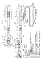
以下、本発明の好ましい実施の形態について図面を参照しつつ詳細に説明する。図1(a)は本発明の一実施の形態に係る汎用油圧工具の操作ユニットの一部を破断した平面図、(b)は汎用油圧工具1を取り付けた状態の一部破断した側面図である。この操作ユニットは、構成を大別すると、作業者が片手で掴持できるグリップ部2と、このグリップ部2の前端に連設された操作部3と、この操作部3の前端に連結された絶縁操作棒4と、この絶縁操作棒4の先端に設けられている汎用油圧工具1が着脱自在に連結される取付部7とを備えて構成されている。
Hereinafter, preferred embodiments of the present invention will be described in detail with reference to the drawings. FIG. 1A is a plan view in which a part of an operation unit of a general-purpose hydraulic tool according to an embodiment of the present invention is broken, and FIG. 1B is a side view in which the general-purpose
図2は上記操作ユニットの後側部分(図1の右側部分)を示す切断側面図である。上記グリップ部2は、前端部が操作部3にねじ結合された円筒状のグリップ芯金部材8と、このグリップ芯金部材8の後端開口部を施蓋するゴム栓9と、グリップ芯金部材8の外表面を覆う熱収縮チューブ10とを備えて構成されている。
FIG. 2 is a cut side view showing a rear portion (right portion in FIG. 1) of the operation unit. The
上記操作部3は、上面開口した容器状のスイッチケース11を備え、このスイッチケース11の後端から突出した連結部11aの雄ねじ部がグリップ芯金部材8の雌ねじ部に螺合されて、スイッチケース11の後端にグリップ芯金部材8が連結されている。このスイッチケース11の開口部には、3つの操作スイッチ12〜14が貫通固着されたスイッチ取付板17がねじ18(図1)により固定されている。各操作スイッチ12〜14は、スイッチ取付板17の上面に固着されたスイッチカバー19によって周囲を覆われている。3つの操作スイッチ12〜14は、この実施の形態において、後述の把持用、圧縮用および加圧解除用の各電磁切換弁に対する通電を制御するための把持用、圧縮用及び加圧解除用であって、何れも押圧されているときのみ接点が閉じられる自動復帰式の押釦スイッチからなる。これら各操作スイッチ12〜14は、スイッチケース11の底面部に電線クランパ20で固定されたコネクタ21に接続されている。コネクタ21に接続された接続電線22の先端部にはプラグ23(図1)が設けられている。
The
上記スイッチケース11の前側内部には、底面部から前方に向けた直交方向に方向転換して前端部に貫通する油路24が形成されている。この油路24の一端部(図の底面側下部)には、ロータリ軸27の先端部に設けられたスイベルジョイント(管継手)28が連結され、ロータリ軸27にはロータリジョイント29が回動可能に設けられている。ロータリジョイント29には、図1に示すように、一端部に油圧取出口ジョイント30を有する高圧ホース31の他端部が、互いに着脱自在に連結される一対の高圧カプラー32a、32bからなる油圧用カプラー式管継手32を介して接続されている。
An
上記スイッチケース11の前端部からは、外周面に雄ねじ部33が形成され、且つ内側に油路24が延出形成された連結部34が一体に突設されており、この連結部34には、油圧用カプラー式管継手37の固定側高圧カプラー(ボディ)37aがねじ結合により連結されている。さらに、上記油圧用カプラー式管継手37の可動側高圧カプラー(ノーズ)37bには、絶縁操作棒4に内装された高圧ホース38の一端部が、ホース継手39を介して連結されている。
From the front end portion of the
上記絶縁操作棒4は筒状のジョイントバー40を介してスイッチケース11の連結部34に連結されている。すなわち、ジョイントバー40の一端部(図の右側部)は、内周面に形成された雌ねじ部41を連結部34の雄ねじ部33に螺合させてスイッチケース11に連結されているとともに、ジョイントバー40の他端部(図の左端部)は、これの外周面に形成された雄ねじ部42に螺合された締付けナット43が締付けられることにより、絶縁操作棒4の外周面を回動不能状態に掴持している。
The insulating operating rod 4 is connected to the connecting
図3は操作ユニットの前側部分(図の左側部分)を示す切断側面図である。絶縁操作棒4に内装された高圧ホース38の前端部は、ロータリジョイント44の固定側ジョイント部47に突設された連結部47aにホース継手49を介して連結されている。絶縁操作棒4は、これの前端部を連結部47aに対し外嵌した状態で止めねじ50で固定されて、ロータリジョイント44に連結されている。この絶縁操作棒4とロータリジョイント44との連結部分は、熱収縮チューブ51を被覆して、外部に対して確実な電気絶縁が図られている。
FIG. 3 is a cut side view showing a front side portion (left side portion of the drawing) of the operation unit. The front end portion of the high-
この操作ユニットでは、絶縁操作棒4の先端側に、ロータリジョイント44および取付部7を介して汎用油圧工具1が取り付けられているので、図1(a)に矢印で示すように、汎用油圧工具1を絶縁操作棒4に対し180度の角度範囲における所要の方向に配置した状態で固定して使用することができる。すなわち、可動側ジョイント部48の上面には、図1(a)に示すように、5個の係止孔45が形成されており、これらの係止孔45には、ストッパピン46が択一的に嵌入するようになっている。ストッパピンは係止孔45に嵌入する方向に圧縮コイルばね(図示せず)により常時付勢されている。汎用油圧工具1の配置を変更する場合には、ストッパピン46を係止孔45から抜脱した状態で、可動側ジョイント部48を回動させて汎用油圧工具1を所要の配置に設定したのちに、ばねで付勢されたストッパピン46を係止孔45を挿入させることにより、汎用油圧工具1が設定位置に固定される。
In this operation unit, since the general-purpose
ロータリジョイント44の可動側ジョイント部48には、取付部7を構成する油圧用カプラー式管継手52の固定側高圧カプラー(ボディ)52aが連結されており、その可動側高圧カプラー(ノーズ)52bが汎用油圧工具1に固着されている。可動側高圧カプラー52bの内部には、汎用油圧工具1の油流路継手53が連結されている。この油圧用カプラー式管継手52は、スイッチケース11の連結部34と絶縁操作棒4に内装の高圧ホース38のホース継手39とを連通連結する油圧用カプラー式管継手37に対し着脱自在に連結可能な互換性を有するものである。すなわち、一方の油圧用カプラー式管継手37の固定側高圧カプラー37aに他方の油圧用カプラー式管継手52の可動側高圧カプラー52bを連結することが可能である。
The movable side
なお、上記各油圧用カプラー式管継手37、52は、ガス配管などに用いられている周知のものであることから、その内部構成の図示を敢えて省略しているが、以下のような着脱構造になっている。すなわち、各油圧用カプラー式管継手37、52は、固定側高圧カプラー37a、52aの操作カラー37c、52cを図の右方にばね(図示せず)の付勢力に抗してスライドさせると、可動側高圧カプラー37b、52bに形成された係合溝(図示せず)に係合していた複数個の鋼球(図示せず)が操作カラー37c、52cによって係合溝に対し係合を解除される方向に移動されて、可動側高圧カプラー37b、52bが固定側高圧カプラー37a、52cに対し挿抜可能状態となる。
The hydraulic coupler-type pipe joints 37 and 52 are well-known ones used for gas piping and the like, and the internal configuration is not shown. It has become. That is, when each of the hydraulic coupler-type pipe joints 37 and 52 slides the
一方、操作カラー37c、52cを元の位置に戻すと、鋼球が係合溝に落ち込みロックされて、可動側高圧カプラー37b、52bが固定側高圧カプラー37a、52aに対し抜脱不能状態に連結される。この連結状態時には、互いのポペットが押し合って開くことによって内部の油圧回路が相互に連通される。一方、可動側高圧カプラー37b、52bを固定側高圧カプラー37a、52aから抜脱した際には、ポペットがスプリング(図示せず)の付勢力によりシート面に密着されて、各々の油圧回路がそれぞれ遮断される。
On the other hand, when the
ところで、汎用油圧工具1は一般に重量が比較的大であることから、油圧用カプラー式管継手52を有する取付部7を介して絶縁操作棒4に連結しただけでは、汎用油圧工具1が油圧用カプラー式管継手52を介して軸心回りに回動してしまう。そこで、上記操作ユニットには、図4に示すように、ホルダ35を用いた回り止め手段が設けられている。同図(a)はホルダ35を開いた状態の平面図、(b)はホルダ35で汎用油圧工具1を固定した状態の側面図、(c)は(b)のA−A線断面図、(d)は(b)のB−B線断面図である。
By the way, since the general-purpose
上記ホルダ35は、油圧用カプラー式管継手52の上面側および一側面側を覆う逆L形の形状を有して、セットボルト36により可動側ジョイント部48に上面に回動自在に支持されている。ホルダ35の先端部に設けられたホルダケース55には、(c)に示すように、外形六角形の可動側高圧カプラー52bの半部に外嵌する固定部材56が回動可能に設けられ、固定部材56を固定するためのボルト65がロックナット66に螺合されている。また、ホルダ35の中間部内部には、(d)に示すように、弾性力を有するばね部材をコ字形状に屈曲してなるクリッパ73が取り付けられており、このクリッパ73は、ホルダ35が(b)に示すように油圧用カプラー式管継手52を覆う状態にセットされたときに、油圧用カプラー式管継手52のボディ部52bに対し両側から挟みこむ状態に係合する。
The
したがって、油圧用カプラー式管継手52を介して汎用油圧工具1を可動側ジョイント部48に取り付ける場合には、ホルダ35を図4(a)に示すように回動して油圧用カプラー式管継手52から離間する位置に配置した状態において、汎用油圧工具1を油圧用カプラー式管継手52を介して可動側ジョイント部48に取り付ける。つぎに、ホルダ35を回動して元の位置に戻し、固定部材56を回転させて位置を調整しながら可動側高圧カプラー52bに外嵌させる。このとき、油圧用カプラー式管継手52のボディ部52dにはクリップ73が対向両側から挟みこむように係合する。最後に、ボルト65をねじ込むことにより、固定部材56をホルダーケース55に固定する。これにより、汎用油圧工具1はホルダ35によって可動側ジョイント部48に回り止め状態に固定される。
Therefore, when the general-purpose
図5は上記操作ユニットに接続される油圧配管系および電気接続系を示す概略ブロック構成図である。同図には、図7に示した電設工事に用いる場合を例示してあり、図7と同一若しくは同等のものには同一の符合を付してある。高所作業車80には、作動油の油タンク54、ドレンタンク57、駆動源のエンジン58、このエンジン58の機械的エネルギを作動油の流体エネルギに変換する油圧ポンプ59などが搭載されている。
FIG. 5 is a schematic block diagram showing a hydraulic piping system and an electrical connection system connected to the operation unit. In the figure, the case where it is used for the electric construction shown in FIG. 7 is illustrated, and the same reference numerals are given to the same or equivalent parts as in FIG. The
バケット84には制御盤などを備えた制御装置85が搭載されており、この制御装置85には、増圧器88、この増圧器88の加圧力を制御する第1ないし第3の電磁切換弁60、61、62、リリーフ弁63、3個の逆止弁64、67、68および電源部(図示せず)などが設けられている。増圧器88の出力部は油圧取出口ジョイント69に配管接続されており、この油圧取出口ジョイント69には、図1(b)の油圧取出口ジョイント30が着脱自在に接続される。これにより、増圧器88からの作動油の出力油圧は、高圧ホース31および操作ユニットの内部の油圧配管を介して汎用油圧工具1に作用するようになっている。また、各電磁切換弁60、61、62はコネクタ70に接続されており、このコネクタ70には、図1(b)のプラグ23が着脱自在に接続される。これにより、第1ないし第3の電磁切換弁60、61、62への電源部(図示せず)からの通電は、把持用、圧縮用および解除用の各操作スイッチ12、13、14をオン・オフ操作することにより制御することができるようになっている。
A
つぎに、上記実施の形態の操作ユニットの手動操作による作用について説明する。この実施の形態では、汎用油圧工具1として、図1に示すような一対の切断部71、72を有する電線カッターを取り付けた場合を例示してあるが、上記操作ユニットは、電線カッター以外の工事に応じて適宜選択した汎用油圧工具を油圧用カプラー式管継手52を有する取付部7を介して可動側ジョイント部48に取り付けることができる。
Next, the operation by manual operation of the operation unit of the above embodiment will be described. In this embodiment, the case where an electric wire cutter having a pair of cutting
先ず、作業者は、グリップ部2と絶縁操作棒4の適所とをそれぞれ握って、汎用油圧工具1の一対の切断部71、72の間に既設架線における切断すべき箇所を挿入させる操作を行う。この状態において、作業者は、グリップ部2を握っている方の手の指で把持用操作スイッチ12を押圧操作する。これにより、第1の電磁切換弁60は、上記把持用操作スイッチ12のオンにより電源部から通電されて励磁するので、油圧ポンプ59からの作動油は、逆止弁64および油圧回路74、75を介して増圧器88における小型シリンダに流入する。これにより発生する140kgf/cm2〜170kgf/cm2程度の油圧は高圧ホース31および操作ユニット内部の油圧配管を通じて汎用油圧工具1に加わり、この油圧によって一対の切断部71、72が電線を挟んだ状態に把持する。
First, the operator performs an operation of inserting the portion to be cut in the existing overhead wire between the pair of cutting
作業者は、上記一対の切断部71、72で挟んだ電線の部位が切断すべき所定箇所であるが否かを目視で判断する。把持した部位が切断すべき箇所と一致している場合には、作業者が汎用油圧工具1から瞬時的に目を離して圧縮用操作スイッチ13の位置を確認した後に、即材に汎用油圧工具1に目線を戻して、把持した部位が切断すべき箇所と一致しているのを確認してから圧縮用操作スイッチ13を押圧操作する。これにより、第2の電磁切換弁61は、上記圧縮用操作スイッチ13のオンにより電源部から通電されて励磁するので、油圧ポンプ59からの作動油は、逆止弁64、油圧回路74および逆止弁67を介して増圧器88の大型シリンダに流入し、ピストンロッドを強力に前進させる。これにより発生する700kgf/cm2程度の大きな油圧は高圧ホース31および操作ユニット内部の油圧配管を通じて汎用油圧工具1に加わり、この油圧によって一対の切断部71、72が把持している電線を切断する。
An operator visually determines whether or not the portion of the electric wire sandwiched between the pair of cutting
電線の切断が終了した後は、作業者が続いて加圧解除用操作スイッチ14を押圧操作する。これにより、第3の電磁切換弁62は、上記加圧解除用操作スイッチ14のオンにより電源部から通電されて励磁するので、油圧ポンプ59からの作動油が油圧回路74を介し増圧器88のロッド側に補給されてピストンロッドが後退され、作動油は逆止弁68、油圧回路74およびリリーフ弁63を通って油圧タンク54に戻されるとともに、増圧器88における小型シリンダの流出油が油圧回路75を介してドレンタンク57に排出される。これにより、操作ユニットの内部の油圧配管の圧力は下がるので、汎用油圧工具1の一対の切断部71、72が開く。
After the cutting of the electric wire is completed, the operator continues to press the pressure
従って、この実施の形態の操作ユニットに汎用油圧工具1を連結して使用すれば、バケット84に搭乗した作業者は、操作ユニットにおけるグリップ部2を握っている方の手の指で3種の操作スイッチ12〜14を択一的に押圧操作しながら、1人で容易に、且つ確実に電線の切断作業を行うことができる。そのため、この操作ユニットを用いた作業では、補助作業者が不要であるから、従来の2人の作業者が動作を行う前毎に互いに合図によって確認しながら行う作業に比較して、格段に作業性が向上するので、施工時間が短縮すると共に、1人の作業者のみによって作業を行うことから、予定外の部材の切断や屈曲といった不具合が生じることがない。また、各操作スイッチ12〜14は、操作ユニットに設けられているので、従来のように制御盤に設けられているように何らかの物が衝突して破損するといったことが防止される。
Therefore, if the general-purpose
また、この実施の形態の操作ユニットは、絶縁操作棒4を一体に具備しているので、活線状態の高圧線に対して絶縁操作棒4を用いた遠隔操作による間接活線作業で電設工事を行える、いわゆる「ホットステック工法」を採用することができ、天候に左右されない全天候作業が可能となる。 In addition, since the operation unit of this embodiment is integrally provided with the insulating operation rod 4, the electrical installation work is performed by indirect hot line operation by remote operation using the insulation operation rod 4 for the high-voltage line in the live line state. The so-called “hot stick method” can be adopted, and all-weather work independent of the weather is possible.
さらに、上記操作ユニットでは、絶縁操作棒4の先端部に取り付けた汎用油圧工具1の配置を絶縁操作棒4に対し180°の角度内で変更して固定できるようになっている。したがって、絶縁操作棒4を用いた間接活線作業を行う場合であっても、作業状況に応じて汎用油圧工具1の取付方向を設定することにより、使い勝手の良いものとなる。
Further, in the operation unit, the arrangement of the general-purpose
しかも、上記操作ユニットは、スイッチケース11と絶縁操作棒4とを各々の油圧配管系を連通させて連結する油圧用カプラー式管継手37と、絶縁操作棒4と汎用油圧工具1とを各々の油圧配管系を連通させて連結する油圧用カプラー式管継手52とが、互換性を有する同一のものであるから、図6に示すように、絶縁操作棒4を除外して、油圧用カプラー式管継手37の固定側高圧カプラー37aに油圧用カプラー式管継手52の可動側高圧カプラー52bを連結することにより、操作部3のスイッチケース11に汎用油圧工具1を直接的に取り付けた形態としても使用することができる。この場合、汎用油圧工具1は、締付けナット43の締付けによりジョイントバー40で外周面を掴持されて、回り止めされる。このような形態とすれば、例えば晴天の日や高圧線が活線でない場合には、絶縁操作棒4を特に必要としないことから、電設工事を直接作業で一層容易に行うことができる。この場合においても、3種の操作スイッチ12〜14の押圧操作によって汎用油圧工具1を自在に作動させることができるから、1人の作業者によって容易に、且つ確実に作業を行える。
In addition, the operation unit includes a hydraulic coupler-type pipe joint 37 that connects the
1 汎用油圧工具
2 グリップ部
3 操作部
4 絶縁操作棒
13 圧縮操作スイッチ(加圧用操作スイッチ)
14 加圧解除用操作スイッチ
22 接続電線(電気配線)
24 油路
31 高圧ホース(フレキシブル油圧配管)
37 油圧用カプラー式管継手(第2の油圧用管継手)
38 高圧ホース(油管)
52 油圧用カプラー式管継手(第1の油圧用管継手)
53 油流路継手(作動油流路)
60、61、62 電磁切換弁
85 制御装置
88 増圧器(油圧切換部)
40 ジョイントバー
35 ホルダ
52a 固定側高圧カプラー(絶縁操作棒側継手部)
52b 可動側高圧カプラー(汎用油圧工具側継手部)
DESCRIPTION OF
14 Pressure
24
37 Hydraulic coupler type fittings (second hydraulic fittings)
38 High-pressure hose (oil pipe)
52 Hydraulic coupler type fittings (first hydraulic fittings)
53 Oil passage joint (hydraulic oil passage)
60, 61, 62
40
52b Movable high pressure coupler (General hydraulic tool side joint)
Claims (1)
作業者が片手で掴むことにできるグリップ部と、
前記グリップ部に連設され、油圧回路における油圧の少なくとも加圧用および加圧解除用の2種の操作スイッチと、両端が外部に開口した油路とを有する操作部と、
内装された油管の一端部が前記操作部の油路の一端部に連通接続され、且つ前記汎用油圧工具の作動油流路に前記油管の他端部を連通して前記汎用油圧工具を着脱自在に連結させる第1の油圧用管継手を有する絶縁操作棒と、
別体に設けられた制御装置に配設されて油圧回路の油圧を切り換える油圧切換部に前記操作部の油路の他端部を連通接続するフレキシブル油圧配管と、
前記制御装置に設けられて前記油圧切換部を切換制御する電磁切換弁に前記各操作スイッチを接続する電気配線とを備え、
前記操作部の油路の一端部に、前記第1の油圧用管継手と連結可能な互換性を有する第2の油圧用管継手が設けられて、前記操作部が、前記第2の油圧用管継手を介して前記絶縁操作棒の前記油管または前記汎用油圧工具の前記作動油流路の何れかに選択的に連通連結できるように構成されるとともに、前記絶縁操作棒または前記汎用油圧工具の各々の連結部分を回動不能状態に掴持するジョイントバーが連設され、
前記絶縁操作棒の前記油管の他端部に回動自在に設けられたホルダには、回動して所定位置に設定されたときに、前記第1の油圧用管継手の前記絶縁操作棒側継手部及び前記汎用油圧工具側継手部のうち、前記絶縁操作棒側継手部に対して係合するクリッパと、軸周りに回動可能に設けられて前記汎用油圧工具側継手部の側方の半部に対して外嵌可能な固定部材と、前記固定部材と一体形成されたボルトとの締結により前記固定部材を回動不能に固定するロックナットとを備え、
前記各操作スイッチの手動操作により、前記電磁切換弁を介し前記油圧切換部の油圧を切り換えて前記汎用油圧工具の作動を制御するように構成されていることを特徴とする汎用油圧工具の操作ユニット。 Various general-purpose hydraulic tools are detachably connected to the tip, and the general-purpose hydraulic tools are controlled by manual operation.
A grip part that an operator can hold with one hand,
An operation unit that is connected to the grip unit and has at least two types of operation switches for pressurization and release of the hydraulic pressure in the hydraulic circuit, and an oil passage having both ends opened to the outside;
One end of the oil pipe installed is connected to one end of the oil passage of the operation section, and the other end of the oil pipe is connected to the hydraulic oil passage of the general-purpose hydraulic tool so that the general-purpose hydraulic tool can be attached and detached. An insulating operating rod having a first hydraulic pipe joint to be connected to
A flexible hydraulic pipe disposed in a separate control device and connected to the other end of the oil passage of the operation section in communication with a hydraulic pressure switching section that switches the hydraulic pressure of the hydraulic circuit;
Electric wiring for connecting each operation switch to an electromagnetic switching valve provided in the control device for switching and controlling the hydraulic pressure switching unit ;
A second hydraulic pipe joint that is connectable to the first hydraulic pipe joint is provided at one end of the oil passage of the operation section, and the operation section is configured to be connected to the second hydraulic pipe joint. It is configured to be able to selectively communicate with either the oil pipe of the insulating operation rod or the hydraulic oil flow path of the general-purpose hydraulic tool via a pipe joint, and the insulating operation rod or the general-purpose hydraulic tool. A joint bar that holds each connecting part in a non-rotatable state is connected,
The holder provided rotatably at the other end of the oil pipe of the insulating operation rod is turned to a predetermined position when the holder is rotated and set at a predetermined position. Of the joint part and the general hydraulic tool side joint part, a clipper that engages with the insulation operating rod side joint part, and a pivotal rotation provided around the axis, on the side of the general hydraulic tool side joint part. A fixing member that can be externally fitted to the half, and a lock nut that fixes the fixing member in a non-rotatable manner by fastening with a bolt integrally formed with the fixing member;
A general-purpose hydraulic tool operation unit configured to control the operation of the general-purpose hydraulic tool by switching the hydraulic pressure of the hydraulic pressure switching unit through the electromagnetic switching valve by manual operation of the operation switches. .
Priority Applications (1)
| Application Number | Priority Date | Filing Date | Title |
|---|---|---|---|
| JP2007227654A JP5156302B2 (en) | 2007-09-03 | 2007-09-03 | General-purpose hydraulic tool operation unit |
Applications Claiming Priority (1)
| Application Number | Priority Date | Filing Date | Title |
|---|---|---|---|
| JP2007227654A JP5156302B2 (en) | 2007-09-03 | 2007-09-03 | General-purpose hydraulic tool operation unit |
Publications (2)
| Publication Number | Publication Date |
|---|---|
| JP2009056571A JP2009056571A (en) | 2009-03-19 |
| JP5156302B2 true JP5156302B2 (en) | 2013-03-06 |
Family
ID=40552792
Family Applications (1)
| Application Number | Title | Priority Date | Filing Date |
|---|---|---|---|
| JP2007227654A Active JP5156302B2 (en) | 2007-09-03 | 2007-09-03 | General-purpose hydraulic tool operation unit |
Country Status (1)
| Country | Link |
|---|---|
| JP (1) | JP5156302B2 (en) |
Families Citing this family (5)
| Publication number | Priority date | Publication date | Assignee | Title |
|---|---|---|---|---|
| CN102814809A (en) * | 2012-08-22 | 2012-12-12 | 王茂博 | Lockable gripper |
| JP5872608B2 (en) * | 2014-03-17 | 2016-03-01 | 中国電力株式会社 | Hydraulic cutter |
| KR101963537B1 (en) * | 2017-09-01 | 2019-03-28 | 대원전기 주식회사 | Indirect live wire method and High voltage Insulated gear gripper Pliers Stick |
| JP7235619B2 (en) * | 2019-07-30 | 2023-03-08 | 株式会社オグラ | hydraulic actuator |
| JP2024043731A (en) * | 2022-09-20 | 2024-04-02 | マクセルイズミ株式会社 | Electric tool |
Family Cites Families (6)
| Publication number | Priority date | Publication date | Assignee | Title |
|---|---|---|---|---|
| JPH047606Y2 (en) * | 1986-02-19 | 1992-02-27 | ||
| JPH047609Y2 (en) * | 1986-09-18 | 1992-02-27 | ||
| JP2569075Y2 (en) * | 1992-04-16 | 1998-04-22 | 株式会社泉精器製作所 | Hydraulic tool rotation prevention member for insulated operating rod |
| JP2560243Y2 (en) * | 1992-04-27 | 1998-01-21 | 株式会社泉精器製作所 | Insulated operating rod protective cover |
| JP2595411Y2 (en) * | 1993-03-22 | 1999-05-31 | 株式会社泉精器製作所 | Insulation holder for hydraulic tools |
| JP4079360B2 (en) * | 2002-10-10 | 2008-04-23 | 株式会社泉精器製作所 | Structure for fixing shaft rotation and swinging rotation of hydraulic tool in insulated operation rod |
-
2007
- 2007-09-03 JP JP2007227654A patent/JP5156302B2/en active Active
Also Published As
| Publication number | Publication date |
|---|---|
| JP2009056571A (en) | 2009-03-19 |
Similar Documents
| Publication | Publication Date | Title |
|---|---|---|
| JP5156302B2 (en) | General-purpose hydraulic tool operation unit | |
| US5253554A (en) | Power driven hose clamp tool | |
| US4453566A (en) | Hydraulic subsea control system with disconnect | |
| EP2054635B1 (en) | A hydraulic connection assembly with a pressure discharge control, positionable between an onboard hydraulic circuit of an engineering vehicle and a removable hydraulic equipment | |
| US6425416B1 (en) | Fluid directional control device for solenoid valve assembly | |
| EP0400897B1 (en) | High pressure gas charging apparatus | |
| US10093010B2 (en) | Multi-stage hydraulic tool | |
| CN101379337A (en) | Multiconnector for a conduit | |
| JP2017055498A (en) | Earth Hook | |
| US11940054B2 (en) | Safety valve for hydraulic or pneumatic tool | |
| CA2452081A1 (en) | Valve assembly | |
| JP2010105048A (en) | Electrohydraulic pressing device having removable hose assembly | |
| CA2346571C (en) | Remote actuation of installation tooling pump | |
| US20200139520A1 (en) | Fluid-powered torque wrench with fluid pump controls | |
| CN208280925U (en) | A kind of safety-type prevention tubing tongs | |
| KR100402755B1 (en) | A Clamp for Assistance Aam that work in no blackout state | |
| JP4026420B2 (en) | Compressed air supply device | |
| JPH047606Y2 (en) | ||
| JP4693383B2 (en) | Concatenated adapter and method of use | |
| US10458445B2 (en) | Device for relieving pressure in hydraulics lines | |
| JPS636866Y2 (en) | ||
| JPH11230394A (en) | Connecting equipment for fluid circuit piping | |
| JP4243857B2 (en) | Malfunction prevention device in fluid sequence equipment |
Legal Events
| Date | Code | Title | Description |
|---|---|---|---|
| A621 | Written request for application examination |
Free format text: JAPANESE INTERMEDIATE CODE: A621 Effective date: 20100729 |
|
| RD02 | Notification of acceptance of power of attorney |
Free format text: JAPANESE INTERMEDIATE CODE: A7422 Effective date: 20100729 |
|
| A521 | Request for written amendment filed |
Free format text: JAPANESE INTERMEDIATE CODE: A821 Effective date: 20100729 |
|
| A977 | Report on retrieval |
Free format text: JAPANESE INTERMEDIATE CODE: A971007 Effective date: 20120427 |
|
| A131 | Notification of reasons for refusal |
Free format text: JAPANESE INTERMEDIATE CODE: A131 Effective date: 20120529 |
|
| A521 | Request for written amendment filed |
Free format text: JAPANESE INTERMEDIATE CODE: A523 Effective date: 20120730 |
|
| TRDD | Decision of grant or rejection written | ||
| A01 | Written decision to grant a patent or to grant a registration (utility model) |
Free format text: JAPANESE INTERMEDIATE CODE: A01 Effective date: 20121204 |
|
| A61 | First payment of annual fees (during grant procedure) |
Free format text: JAPANESE INTERMEDIATE CODE: A61 Effective date: 20121210 |
|
| FPAY | Renewal fee payment (event date is renewal date of database) |
Free format text: PAYMENT UNTIL: 20151214 Year of fee payment: 3 |
|
| R150 | Certificate of patent or registration of utility model |
Ref document number: 5156302 Country of ref document: JP Free format text: JAPANESE INTERMEDIATE CODE: R150 Free format text: JAPANESE INTERMEDIATE CODE: R150 |
|
| R250 | Receipt of annual fees |
Free format text: JAPANESE INTERMEDIATE CODE: R250 |
|
| R250 | Receipt of annual fees |
Free format text: JAPANESE INTERMEDIATE CODE: R250 |
|
| R250 | Receipt of annual fees |
Free format text: JAPANESE INTERMEDIATE CODE: R250 |
|
| R250 | Receipt of annual fees |
Free format text: JAPANESE INTERMEDIATE CODE: R250 |
|
| R250 | Receipt of annual fees |
Free format text: JAPANESE INTERMEDIATE CODE: R250 |
|
| R250 | Receipt of annual fees |
Free format text: JAPANESE INTERMEDIATE CODE: R250 |