JP5155826B2 - Manufacturing method of display device - Google Patents
Manufacturing method of display device Download PDFInfo
- Publication number
- JP5155826B2 JP5155826B2 JP2008293635A JP2008293635A JP5155826B2 JP 5155826 B2 JP5155826 B2 JP 5155826B2 JP 2008293635 A JP2008293635 A JP 2008293635A JP 2008293635 A JP2008293635 A JP 2008293635A JP 5155826 B2 JP5155826 B2 JP 5155826B2
- Authority
- JP
- Japan
- Prior art keywords
- adhesive
- display panel
- translucent substrate
- liquid crystal
- substrate
- Prior art date
- Legal status (The legal status is an assumption and is not a legal conclusion. Google has not performed a legal analysis and makes no representation as to the accuracy of the status listed.)
- Expired - Fee Related
Links
Images


Description
本発明は、表示装置の表示面に透光性接着剤により透光性基板を貼り付けた表示装置の製造方法に関する。 The present invention relates to a method for manufacturing a display device in which a light-transmitting substrate is attached to a display surface of a display device with a light-transmitting adhesive.
表示パネルの表示面には表示面保護用や耐衝撃用のカバーガラスが設置されている。また、カバーガラスに代えてタッチパネルが設置された表示装置も知られている。しかし、表示パネルとカバーガラスやタッチパネルとの間に空気層が介在すると、表示パネルの表面やカバーガラス又はタッチパネルの下側表面で光が反射し、この反射損により表示面が暗くなる不具合が生じた。これを解決する方法として、表示パネルとカバーガラス又はタッチパネルの間にガラスの屈折率に近い屈折率を有する透明接着剤を充填する方法が提案されている。この構造によれば、表示パネルの表示側表面やカバーガラスの表示パネル側表面での反射損失を低減させることができる。更に、カバーガラスと表示パネルが接着剤により一体化するために、耐衝撃性が向上する利点がある。 On the display surface of the display panel, a cover glass for protecting the display surface and for shock resistance is installed. A display device in which a touch panel is installed instead of the cover glass is also known. However, if an air layer is interposed between the display panel and the cover glass or touch panel, light is reflected on the surface of the display panel, the lower surface of the cover glass or the touch panel, and the display surface becomes dark due to this reflection loss. It was. As a method for solving this, a method of filling a transparent adhesive having a refractive index close to the refractive index of glass between a display panel and a cover glass or a touch panel has been proposed. According to this structure, the reflection loss on the display side surface of the display panel and the display panel side surface of the cover glass can be reduced. Furthermore, since the cover glass and the display panel are integrated by an adhesive, there is an advantage that impact resistance is improved.
特許文献1には、タッチパネルと表示パネルの間に透明接着剤を充填したタッチパネル付き表示装置が記載されている。タッチパネルと表示パネルの間に透明接着剤を充填する方法は次のとおりである。まず、タッチパネルの裏面を上方に向けて透明接着剤を塗布する。次に、これを反転して、透明接着剤の液だれを形成する。次に、液だれが形成されたタッチパネルを表示パネルの上方からゆっくり降下させて貼り合わせる。透光性基板を降下させると、透明接着剤からなる液だれの先端が表示パネルの表面に接触し、接触面が次第に周辺へ広がる。このように充填すると、透明接着剤に気泡が混入することを防止することができる。
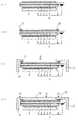
図11(a)は、上記方法により液晶パネル58上に保護用ガラス基板61を貼り付ける貼り付け方法を表す断面図である。液晶パネル58は、上ガラス基板51と、シール材54により間隙を形成するように貼り付けられた下ガラス基板52と、その間隙に封入された液晶53と、上ガラス基板51の端部下面に実装されたIC57と、上ガラス基板51の外面に貼り付けられた上偏光板55と、下ガラス基板52の外面に貼り付けられた下偏光板56とから構成されている。液晶パネル58の下部にはバックライト59が設置されている。液晶パネル58の周囲には枠体60が設置され、枠体60の上部には開口部65が形成され、液晶パネル58の表示面が見えるように構成されている。
FIG. 11A is a cross-sectional view illustrating a pasting method in which the
この構造体の表示面側に接着する保護用ガラス基板61の表面に、液体の透明接着剤62を塗布する。透明接着剤62としてUV硬化型の透明接着剤を使用する。保護用ガラス基板61は、枠体60の上部の開口部65よりもやや大きい形状を有し、開口部65の上端部66に重なる。透明接着剤62は1000〜6000mPa・sの粘度を有し、反転したときに液だれが形成される。この保護用ガラス基板61を矢印方向にゆっくり降下させて、保護用ガラス基板61、枠体60の上端部66及び液晶パネル58を一体的に接着する。接着の際には紫外線を照射する。
図11(b)は、保護用ガラス基板61、枠体60の上端部66及び液晶パネル58を接着した状態を表す断面図である。図11(c)はその上面図である。枠体60の上端部66の板厚は約0.3mm有する。上端部66と上偏光板55又は上ガラス基板51の上面との間には0mm〜0.3mmの隙間がある。枠体60の上端部66と上偏光板55又は上ガラス基板51との間に隙間がある場合には、矢印63に示すように、透明接着剤62が液晶パネル58と枠体60の間を流れ出してバックライト59にまで達し、バックライト59等のメンテナンス不能となる不具合が発生した。
FIG. 11B is a cross-sectional view illustrating a state in which the
また、枠体60の上端部66と上偏光板55又は上ガラス基板51との間に隙間をなくして形成すると、上端部66の先端部に空隙64が形成される。図11(c)に示すように、枠体60の開口部65のコーナー部や右辺部に空隙64が形成されると、この空隙64が見えてしまう。また、透明接着剤62は硬化する際に体積が収縮する。透明接着剤62の体積が収縮すると液晶パネル58の表示面に引っ張り応力が加わる。そのために、液晶パネルに反りや液晶層の厚みむらを生じ、色むらが発生する、という不具合があった。
Further, when the gap is formed between the
上記の課題を解決するために本発明は、表示パネルを、上部に開口部を備える枠体の内側に該枠体の開口部の端部に近接して配置した後、枠体の開口部から露出する表示パネルの露出面に、第1接着剤を充填し第1接着層を形成した。第1接着層により、枠体の開口端部と表示パネルの表面との間の段差が埋まるため、枠体の上端コーナー部や角部に空隙が発生するのを防ぐことができる。次に、開口部の外側に配置した透光性基板の表面に第2接着剤を塗布し、第2接着剤が塗布された透光性基板を、第2接着剤の塗布面を下面にして、第1接着層が形成された表示パネルの上面に貼り合わせ第2接着剤を硬化することとした。このようにして、表示パネルの上面と透光性基板の下面との間に気泡や空隙を混入することなく接着剤を充填することができる。 In order to solve the above-described problems, the present invention provides a display panel that is disposed on the inner side of a frame body having an opening at the upper part, close to the end of the opening of the frame, and then from the opening of the frame. The exposed surface of the exposed display panel was filled with the first adhesive to form a first adhesive layer. Since the first adhesive layer fills the step between the opening end of the frame and the surface of the display panel, it is possible to prevent a gap from being generated at the upper corner or corner of the frame. Next, the second adhesive is applied to the surface of the translucent substrate disposed outside the opening, and the translucent substrate to which the second adhesive is applied is applied to the lower surface of the application surface of the second adhesive. The second adhesive was cured by bonding to the upper surface of the display panel on which the first adhesive layer was formed. In this manner, the adhesive can be filled without introducing bubbles or voids between the upper surface of the display panel and the lower surface of the translucent substrate.
さらに、第1接着層を形成する工程で、枠体の開口部から露出する表示パネルの露出面に、開口端部の上面の高さと略等しい高さまで第1接着層を形成した。 Further, in the step of forming the first adhesive layer, the first adhesive layer was formed on the exposed surface of the display panel exposed from the opening of the frame body to a height substantially equal to the height of the upper surface of the opening end.
さらに、第1接着層を形成する工程で、透光性基板を貼り合わせる前に、第1接着剤を硬化させることとした。第2接着剤を塗布し硬化させる前に第1接着剤を硬化させることにより、硬化収縮による表示パネルへの応力を低減させることができる。 Further, in the step of forming the first adhesive layer, the first adhesive is cured before the light-transmitting substrate is bonded. By curing the first adhesive before applying and curing the second adhesive, the stress on the display panel due to curing shrinkage can be reduced.
また、第1接着層を形成する前に、表示パネルと枠体の間に接着剤ダムを形成することとした。これにより、第1接着剤が漏れ出して表示パネルの側面下部に落下し他の素子に第1接着剤が付着することを防止することができる。 Further, an adhesive dam is formed between the display panel and the frame before forming the first adhesive layer. Accordingly, it is possible to prevent the first adhesive from leaking out and dropping to the lower side of the side of the display panel and attaching the first adhesive to other elements.
また、第2接着剤を塗布する工程で、相対的に高粘性を有する接着剤を塗布した上に相対的に低粘性を有する接着剤を塗布することとした。 In the step of applying the second adhesive, the adhesive having a relatively high viscosity is applied to the adhesive having the relatively high viscosity.
また、第1接着剤及び第2接着剤は、硬化収縮率が1%〜6%の範囲とした。ここで、第1接着剤と第2接着剤とは硬化後の屈折率が略等しくなる材料を選んだ。 Moreover, the 1st adhesive agent and the 2nd adhesive agent were made into the range whose cure shrinkage rate is 1%-6%. Here, the first adhesive and the second adhesive were selected to have substantially the same refractive index after curing.
表示パネルの上部露出面に、第1接着剤からなる第1接着層を最初に形成し、次に、透光性基板の表面に第2接着剤を塗布し、その塗布面を下方に向けて第1接着層が形成された表示パネルの上面に貼り合わせ、第2接着剤を硬化した。これにより、表示パネルの上面と透光性基板の下面との間に気泡や空隙を混入することなく接着剤を充填することができる、という利点を有する。 First, a first adhesive layer made of a first adhesive is formed on the upper exposed surface of the display panel. Next, a second adhesive is applied to the surface of the translucent substrate, and the applied surface faces downward. The second adhesive was cured by bonding to the upper surface of the display panel on which the first adhesive layer was formed. This has the advantage that the adhesive can be filled without introducing bubbles or voids between the upper surface of the display panel and the lower surface of the translucent substrate.
本発明による表示装置の製造方法を、図1を用いて工程順に説明する。図1(a)は配置工程を表す模式図である。表示装置の枠体10は上部に開口部11を備えている。表示パネル21を枠体10の内側の開口部11に近接して設置する。枠体10の開口端部12と表示パネル21の上面との間に間隙を設けても、接触させてもよい。図1(b)は第1接着層形成工程を表す模式図である。透光性の第1接着剤からなる第1接着層14は表示パネル21の上面に、枠体10の開口端部まで存在するように形成される。図1(c)は第2接着剤塗布工程を表す模式図である。透光性基板16の表面に透光性の第2接着剤17を塗布する。第2接着剤17は、透光性基板16の表面に点状に塗布する。例えば透光性基板16の表面中央部に1点、あるいは、更に隅部に4点塗布する。第2接着剤17の塗布量は、表示パネル21側全面に0.05〜0.3mm程度の厚さに塗布することができる量とする。
A method for manufacturing a display device according to the present invention will be described in the order of steps with reference to FIG. FIG. 1A is a schematic diagram showing an arrangement process. The
図1(d)は、貼り合せ工程を表す模式図である。上下を反転させた透光性基板16を第1接着層14の上方に配置する。配置の際には透光性基板16と表示パネル21及び枠体10との間の位置合わせを行う。第2接着剤17は重力の作用により液だれが形成される。この状態で、透光性基板16をゆっくり降下する。透光性基板16の降下は、液だれの表面に波紋が生じない程度の速度とする。例えば、5〜100μm/secの速度で降下させる。例えば、使用する第2接着剤17の粘度が2000〜3000mPa・sである場合には、降下速度を約20μm/secとする。そして、第2接着剤17と第1接着層14との間の接触面積を拡大させて透光性基板16の下面全体に第2接着剤17を充填する。図1(e)は、第2接着剤硬化工程を表す。第2接着剤17として熱硬化型接着剤を使用した場合には加熱し、UV硬化型接着剤の場合には紫外線を照射し、可視光硬化型接着剤のときは可視光を照射して硬化する。
FIG.1 (d) is a schematic diagram showing a bonding process. The
図2は、第2接着剤硬化工程後の表示装置の上面図を表す。枠体10の内側に透光性基板16が接着され、開口部11から表示パネル21の表示面が見えている。枠体10の開口端部12と表示パネル21の表面との間に形成される段差が、第1接着剤により埋められる、または段差が縮小するので、枠体10の上端コーナー部や角部に空隙が残らない。また、第1接着層14と第2接着剤17の屈折率を透光性基板16及び表示パネル21のそれぞれの屈折率に近似させることにより、透光性基板16と表示パネル21との間の光の反射損、及び第1接着層14と第2接着剤17との間の光の反射損を低減させることができる。
FIG. 2 shows a top view of the display device after the second adhesive curing step. The
上記表示装置の製造方法において、表示パネル21として、液晶パネル、プラズマディスプレイパネル、有機ELパネル等の平面型表示パネルを使用することができる。また、透光性基板16として、表示面保護用のガラス基板、ポリカーボネートやアクリルなどの透明プラスチック基板、入力用タッチパネル等の平板透明基板を使用することができる。第1接着剤及び第2接着剤17として熱硬化型接着剤、UV硬化型接着剤、可視光硬化型接着剤等の透明接着剤を使用することができる。第1の接着剤と第2の接着剤は上記接着剤のうち異なる種類の接着剤を組み合わせてもよい。枠体10として、金属、プラスチック、セラミック等を使用することができる。
In the display device manufacturing method, a flat display panel such as a liquid crystal panel, a plasma display panel, or an organic EL panel can be used as the
なお、上記第1接着層形成工程において、枠体10の開口部11から露出する表示パネル21の露出面に、開口端部12の上面の高さと略等しい高さまで第1接着層14を形成する。これにより、開口端部12の上面と第1接着層14の上面との間の段差がほとんどなくなるので、この部分に第2接着剤17の空隙がより発生し難くなる利点を有する。
In the first adhesive layer forming step, the first
また、上記第1接着剤形成工程の前に、両面テープを表示パネル21上面と枠体10の開口端部12の間に設けることにより、枠体10の開口端部12と表示パネル21の表面との間の間隙を塞いで接着剤ダムを形成することができる。これにより、第1接着層形成工程で第1接着剤を塗布する際に、両面テープがダムとして機能するため、枠体10の開口端部12と表示パネル21との間隙から第1接着剤が漏れ出して表示パネル21の側面下部に落下し他の素子に第1接着剤が付着することを防止することができる。
Further, by providing a double-sided tape between the upper surface of the
あるいは、上記第1接着層形成工程の前に、枠体10の開口端部12と表示パネル21との間に、第3接着剤による接着剤ダムを形成することができる。その後、上記接着剤ダムと表示パネル21の露出面から構成される凹部に第1接着剤を塗布する。これにより、枠体10の開口端部12と表示パネル21との間に間隙がある場合に、この間隙から第1接着剤が漏れ出して表示パネル21の側面下部に落下して他の素子に第1接着剤が付着することを防止することができる。ダムを形成する第3接着剤と表示パネル21の露出面に塗布する第1接着剤とは屈折率が略等しい接着剤を使用することが好ましい。界面からの光の反射を防止するためである。また、第3接着剤は、塗布したときに表示パネル21の表面に広がらないようにする。そのため、第3接着剤の粘度を40000〜80000mPa・s程度とするのが好ましい。
Alternatively, an adhesive dam made of a third adhesive can be formed between the
また、第3接着剤により上記接着剤ダムを形成する場合に、接着剤ダムの上端部が開口端部12上面より高く形成する。これにより、開口端部12の側断面が第3接着剤により覆われるので、後の貼り合せ工程において、第2接着剤17が流れ込んできたときにその段差部で空隙が発生し難くなる。また、透光性基板16の外形が開口部11の外形より大きい場合に、第2接着剤17が流れ込んできたときに外側へ拡散しやすくなり、透光性基板16の下面全体に第2接着剤17を充填することが容易になる。
Moreover, when forming the said adhesive agent dam with a 3rd adhesive agent, the upper end part of an adhesive agent dam is formed higher than the upper surface of the opening
また、第1接着層形成工程において、透光性基板16を貼り合わせる貼り合せ工程の前に、第1接着剤を硬化することができる。これにより、透光性基板16と表示パネル21との間に充填した接着剤の、硬化収縮による応力を低減させることができる。第1接着剤に熱硬化型接着剤、第2接着剤にUV硬化型接着剤のように異なる硬化型接着剤を使用する場合も有効である。
Further, in the first adhesive layer forming step, the first adhesive can be cured before the bonding step of bonding the
図3は、接着剤の硬化収縮による応力を説明するための表示パネル21、接着剤28及び透光性基板16の模式的な断面図である。図3(a)は、表示パネル21と透光性基板16との間に厚さTの接着剤28を充填した状態を示す断面図である。接着剤28はまだ硬化していない。図3(b)は、図3(a)の接着剤28を硬化した状態を表す断面図である。接着剤28は硬化収縮により、厚さδt縮む。表示パネル21と透光性基板16の端部は枠体10の開口端部12を介して固定されている。そのために、表示パネル21の上表面及び透光性基板16の下表面には接着剤28側に向けた引っ張り応力29が発生する。例えば、表示パネル21が液晶パネルである場合には、液晶パネルに反りを発生させる、あるいは、液晶パネルを構成する2枚の基板の上基板が上方に引っ張られる。これにより液晶層の厚さが変化して色むら等が発生する。
FIG. 3 is a schematic cross-sectional view of the
図3(c)〜(e)は、本発明の表示装置の製造方法を説明するための断面図である。図3(c)は、第1接着層形成工程において表示パネル21上に形成した第1接着層14を硬化した状態を表す。第1接着剤が熱硬化型接着剤である場合には加熱して硬化し、UV硬化型接着剤である場合には紫外線を照射して硬化し、可視光型接着剤である場合には可視光を照射して硬化する。硬化した第1接着層14の厚さをT/2とする。硬化の際に第1接着層14に硬化収縮が発生しても、その上面がフリーであることから下部の表示パネル21に応力は印加されない。
3C to 3E are cross-sectional views for explaining a method for manufacturing a display device of the present invention. FIG. 3C shows a state where the first
図3(d)は、貼り合せ工程を表し、第1接着層14と透光性基板16との間に第2接着剤17を充填した状態を表す。第2接着剤17は厚さT/2に充填し、第1接着層14と第2接着剤17の全体の厚さをTとする。図3(e)は、第2接着剤17を硬化して硬化収縮が発生した状態を表す。硬化収縮はδt/2であり、上記第3図(b)の半分の硬化収縮量となる。即ち、先に塗布した接着剤を先に硬化することにより、硬化収縮により表示パネル21へ印加される応力を低減させることができる。なお、第1接着剤及び第2接着剤17の硬化収縮率は小さいことが望ましい。本発明においては、例えば、硬化収縮率が1%〜6%の範囲の接着剤を使用しても、表示パネルに与える応力の影響を低減することができる。
FIG. 3D shows a bonding process, in which the
また、第2接着剤塗布工程は、透光性基板16に相対的に高粘性を有する接着剤を塗布した後に、低粘性を有する接着剤を塗布することができる。本発明の液晶表示装置の製造方法では、貼り合せ工程において透光性基板16に接着剤からなる液だれを形成して透光性基板16と表示パネル21の間に接着剤を充填する。しかし、表示パネル21の表面積が大きくなるに従い使用する接着剤の量が増加する。そこで、透光性基板16の表面に相対的に高粘性の接着剤を先に塗布し、次に上記接着剤よりの低粘性の接着剤を塗布して、接着剤を塗布する領域を拡大させる。具体的には、粘度5000〜10000mPa・sの接着剤を透光性基板16に塗布し、次に、粘度1000〜6000mPa・s、好ましくは2000〜3000mPa・sの接着剤を塗布する。透光性基板16の上下を反転したとき、液だれは主に低粘性の接着剤により形成される。このように2段階で接着剤を塗布することにより、広い面積の表示パネル21に気泡の混入をなくして透光性基板16を貼り付けることができる。なお、本発明においては、2段階に限定されず、更に多段階に接着剤を塗布することができる。この場合は、最後に塗布する接着剤の粘度を先に塗布した接着剤の粘度より低下させる。
Further, in the second adhesive application step, an adhesive having a low viscosity can be applied after applying an adhesive having a relatively high viscosity to the
以下、本発明の表示装置の製造方法について図面を用いて具体的に説明する。同一の部分又は同一の機能を有する部分には同一の符号を付した。また、以下の各実施例では表示パネルとして液晶パネルを使用している。 Hereafter, the manufacturing method of the display apparatus of this invention is demonstrated concretely using drawing. The same reference numerals are assigned to the same parts or parts having the same function. In the following embodiments, a liquid crystal panel is used as the display panel.
(実施例1)
本実施例による表示装置の製造方法を図4に基づき説明する。図4(a)は、液晶パネル8及び枠体10の断面構造を示し、配置工程を表している。液晶パネル8は、ガラスからなる上基板1と下基板2がシール材4を介して対向して貼り合わされ、その間隙に液晶層3が形成されている。上基板1の内面にはTFTマトリックスアレイが形成され、下基板2の内面にはカラーフィルターが形成されている。上基板1の右辺は突出し、突出部の下面にはTFTアレイを駆動するためのドライバーIC7がCOGにより実装されている。上基板1の外面に上偏光板5が、下基板2の外面に下偏光板6が貼り付けられている。液晶パネル8の下部にはバックライト9が設置されている。液晶パネル8及びバックライト9は、例えば図示しない筐体に設置されている。液晶パネル8は数インチから15インチの表示画面を有している。
Example 1
A method of manufacturing the display device according to this embodiment will be described with reference to FIG. FIG. 4A shows a cross-sectional structure of the
枠体10は金属板で形成され、上端には開口部11を有し、下部は図示しない筐体に固定されている。開口部11は開口端部12により仕切られている。液晶パネル8を枠体10の開口端部12に近接して設置する。開口端部12の端部板厚は約0.3〜0.6mmである。開口端部12の先端は、上偏光板5の外周部が平面的に重なる部位まで延在する。開口端部12の下面と上偏光板5の上面との隙間は0mmより大きく約0.3mm程度までである。
The
図4(b)は、液晶パネル8の上面に第1接着層14を形成した様子を示す断面図であり、第1接着層形成工程を表している。液晶パネル8の上面に第1接着剤を塗布する。このとき、接着剤を開口端部12まで塗布する。第1接着剤としてUV硬化型の透明接着剤を使用する。第1接着剤の粘度は、1000〜6000mPa・sである。次に、紫外線を3000〜10000mJ/cm2照射して第1接着剤を硬化させる。第1接着層14は、枠体10の開口端部12の上面13と第1接着層14の上面15とが同程度の高さとする。第1接着剤の上面の凹凸は、約100μmまで許容できるが、100μm以下とするのが好ましい。
FIG. 4B is a cross-sectional view illustrating a state in which the first
図4(c)は、透光性基板16の上面に第2接着剤17を塗布した状態を示す断面図であり、第2接着剤塗布工程を表している。透光性基板16としてガラス基板を使用した。第2接着剤17は、透光性のUV硬化型接着剤を使用した。第2接着剤17の粘度は1000〜6000mPa・sである。第2接着剤17の粘度を高くすると、次の貼り合せ工程で透光性基板16を反転したときに液だれが形成し難くなり、粘度を低くすると、液だれ量が減少して、液晶パネル8と透光性基板16間に充填する第2接着剤17の量が不足する。
FIG. 4C is a cross-sectional view showing a state in which the
図4(d)は、液晶パネル8の上方に第2接着剤17を塗布した面を下面にした透光性基板16の断面構造を示し、貼り合せ工程を表している。透光性基板25の上下を反転して第2接着剤17を下側にする。すると、重力により第2接着剤17は液だれの形状となる。この液だれが形成された状態で、透光性基板16を液晶パネル8の露出面に降下させる。すると、液だれの先端が第1接着層14の表面に点接触する。その後、透光性基板16を更に降下させることにより、第2接着剤17と第1接着層14との接触面は次第に拡大する。この場合に、第2接着剤17からなる液だれが第1接着層14に点接触したときに、液だれの表面に波紋が生じない降下速度で透光性基板16を降下させる。波紋が生ずると、第2接着剤17に気泡が混入するからである。第2接着剤17は透光性基板16の下面表面全面に拡散させる。第1接着層14の表面と開口端部12の上面に段差がほとんどないため、段差部に気泡や空隙が混入することもない。なお、液晶パネル8と透光性基板16間に充填した接着剤に許容される気泡の直径は約100μmまでである。従って、直径が100μmより小さい気泡は問題としていない。
FIG. 4D shows a cross-sectional structure of the
図4(e)は、透光性基板16を液晶パネル8の上部に接着した断面構造を示し、第2接着剤硬化工程を表す。第2接着剤17が透光性基板16の下面全面に拡散した後に、紫外線を照射して第2接着剤17を硬化させる。紫外線は、3000〜10000mJ/cm2照射する。硬化後の第2接着剤17の硬度は、タイプA硬度1〜10である。従って、硬化後の硬度はゴム弾性の性質を有する。硬度が高すぎると、熱膨張等による変形に対して上偏光板5の剥がれや損傷を生じ、硬度が低すぎると、液晶パネル8の耐衝撃性が低下する。
FIG. 4E shows a cross-sectional structure in which the
なお、実施例1において、第1接着層14と第2接着剤17の屈折率は透光性基板16及び上偏光板5の屈折率と近似させている。そのために、上偏光板5と第1接着層14との間の界面、第1接着層14と第2接着剤17との間に界面、第2接着剤17と透光性基板16との間の界面における光の反射損失が低減する。例えば、第1接着層14及び第2接着剤17の屈折率を1.45〜1.55とする。また、透光性基板16として保護用ガラス基板としたが、これに変えて、プラスチック板やタッチパネルを使用することができる。また、UV硬化型接着剤に代えて、熱硬化型接着剤や可視光硬化型接着剤を使用することができる。また、第1接着剤と第2接着剤17にUV硬化型接着剤、熱硬化型接着剤および可視光硬化型接着剤のうち異なる種類の接着剤を組み合わせて使用することもできる。
In Example 1, the refractive indexes of the first
(実施例2)
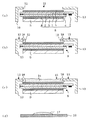
本実施例に係る表示装置の製造方法を図5、図6を用いて説明する。図5(a)は、液晶パネル8及びバックライト9の断面構造を示し、配置工程を表している。液晶パネル8は実施例1の図4(a)と同様であり、説明を省略する。図5(b)は、液晶パネル8の上基板1上面に両面テープ19を貼り付けた状態を表す断面図である。両面テープは液晶パネル8の上基板1上面外周に貼り付けてある。図5(c)は、両面テープ19により液晶パネル8の上基板1と枠体10を貼り合わせた状態を表す断面図である。両面テープ19は、第2接着剤を塗布したときに、枠体10と液晶パネル8との間の隙間から接着剤が漏れ出ないようにし、ダムとして機能する。
(Example 2)
A method of manufacturing the display device according to this example will be described with reference to FIGS. FIG. 5A shows a cross-sectional structure of the
次に、両面テープ19、開口端部12と液晶パネル8の上面により構成される凹部に第1接着剤を塗布して第1接着層14を形成する。図5(d)は、この第1接着層14が形成された状態を模式的に示す断面図で、第1接着層形成工程において第1接着剤を塗布して第1接着層を形成する工程を表している。第1接着剤の粘度は、1000〜6000mPa・sとする。第1接着剤を塗布したときの第1接着剤の上面15の高さと枠体10の上面13との高さを略同程度とする。液晶パネル8の表面に塗布した第1接着剤は両面テープ19によりせき止められ、側面下部に漏れ出すことはない。第1接着剤の表面の凹凸は100μm以下にするのが好ましい。第1接着剤を塗布した後に、紫外線20を照射して、第1接着層14を硬化する。図6(e)は、この第1接着剤層14に紫外線20を照射して第1接着剤層14を硬化する状態を模式的に示す断面図であり、第1接着層形成工程の第1接着剤の硬化工程を表している。このように第1接着層形成工程には第1接着剤を塗布して第1接着剤層14を形成する工程と、第1接着剤層14に紫外線20を照射して第1接着剤層14を硬化する工程が含まれる。
Next, a first
図6(f)は、透光性基板16の表面に第2接着剤17を塗布した状態を表す断面図であり、第2接着剤塗布工程を表している。第2接着剤17は、粘度1000〜6000mPa・sとし、屈折率は第1接着剤と同程度にする。図6(g)は、透光性基板16の上下を反転して液晶パネル8の上に貼り合わせる状態の断面図であり、貼り合せ工程を表している。透光性基板16をゆっくり降下して、第2接着剤の液だれの先端を第1接着層14の表面に点接触させて、接触面を次第に拡大させる。透光性基板16の降下速度は、液だれの表面に波紋が生じない速度とする。第2接着剤17は透光性基板16の下面表面全面に拡散させる。図6(h)は、第2接着剤17を硬化する硬化工程を示す断面図である。図4(e)と同様であり、説明を省略する。
FIG. 6F is a cross-sectional view illustrating a state where the
なお、第1接着剤層14の硬化と第2接着剤17の硬化は別々の工程で行われているので、第1接着剤層14に熱硬化型接着剤を使用し、第2接着剤17にUV硬化型接着剤を使用するなど、異なる硬化型の接着剤を組み合わせて使用することも可能である。
Since the curing of the first
また、本願発明では、液晶パネル8側に両面テープを貼り付けたが、枠体10側に両面テープを貼り付けてもよい。
Moreover, in this invention, although the double-sided tape was affixed on the
(実施例3)
本実施例に係る表示装置の製造方法を図7、図8を用いて説明する。図7(a)は、液晶パネル8を枠体10の開口端部12に近接して配置した断面図であり、配置工程を表している。実施例1の図4(a)と同様であり、説明を省略する。図7(b)は、開口端部12と液晶パネル8の上偏光板5上面との間に第3接着剤からなる接着剤ダム18を形成した状態を表す断面図である。第3接着剤は、粘度10000〜50000mPa・sを有するUV硬化型接着剤を用いた。接着剤ダム18は、第1接着剤を塗布したときに、枠体10と液晶パネル8との間の隙間から接着剤が漏れ出ないようにする。接着剤ダム18は、少なくとも開口端部12を覆うように形成する。接着剤ダム18の上端部は、枠体10の上面13より高く形成するのが好ましい。より好ましくは、接着剤ダム18の上端部が枠体10の上面13よりも略0.1mm高くする。これにより、透光性基板16の貼り合せ工程において、透光性基板16の下面全面に第2接着剤を充填できる。
(Example 3)
A method of manufacturing the display device according to this example will be described with reference to FIGS. FIG. 7A is a cross-sectional view in which the
次に、接着剤ダム18と液晶パネル8の上面により構成される凹部に第1接着剤を塗布して第1接着層14を形成する。図7(c)は、この第1接着層14が形成された状態を模式的に示す断面図である。第1接着層14の粘度は、1000〜6000mPa・sとする。第1接着剤を塗布したときの第1接着剤の上面15の高さと枠体10の上面13との高さを略同程度とする。液晶パネル8の表面に塗布した第1接着剤は接着剤ダム18によりせき止められ、下方に漏れ出すことはない。第1接着剤の表面の凹凸は100μm以下にするのが好ましい。第1接着剤を塗布した後に、紫外線を照射して、接着剤ダム18と第1接着剤とを硬化して、第1接着層14を形成する。接着剤ダム18の屈折率と第1接着剤14とは同程度の屈折率とする。これにより、その境界から光が反射することを防止する。
Next, the first
図7(d)は、透光性基板16の表面に第2接着剤17を塗布した状態を表す断面図であり、第2接着剤塗布工程を表している。第2接着剤17は、粘度1000〜6000mPa・sとし、屈折率は第1接着剤と同程度にする。
FIG. 7D is a cross-sectional view illustrating a state in which the
図8(e)は、透光性基板16の上下を反転して液晶パネル8の上に貼り合わせる状態の断面図であり、貼り合せ工程を表している。透光性基板16をゆっくり降下して、第2接着剤の液だれの先端を第1接着層14の表面に点接触させて、接触面を次第に拡大させる。透光性基板16の降下速度は、液だれの表面に波紋が生じない速度とする。第2接着剤17は次第に接触領域を拡大し、接着剤ダム18に到達する。第2接着剤17の液量や粘性に応じて、第2接着剤17の拡散が接着剤ダム18で止る、あるいは透光性基板16の下面全面に拡散する。図8(f)は、第2接着剤17を硬化する硬化工程を示す断面図である。図4(e)と同様であり、説明を省略する。
FIG. 8E is a cross-sectional view showing a state in which the
(実施例4)
本実施例に係る表示装置の製造方法を図9に基づいて説明する。本実施例は、第2接着剤塗布工程において透光性基板16の表面に第2接着剤17を2回塗布する工程を含む。その他の配置工程、第1接着層形成工程、貼り合せ工程、第2接着剤硬化工程は実施例1〜3と同様なので説明を省略する。
Example 4
A method of manufacturing the display device according to this example will be described with reference to FIG. The present embodiment includes a step of applying the second adhesive 17 to the surface of the
図9(a)は、透光性基板16の表面に相対的に高粘度の第1層目の第2接着剤17を塗布した状態を表す断面図である。第1層目の第2接着剤17は、粘度5000〜10000mPa・sを有するUV効果型接着剤を使用した。図9(b)は、第1層目の第2接着剤17の上に相対的に低粘度の第2層目の第2接着剤17’を塗布した状態を表す断面図である。第2層目の第2接着剤17’は第1層目の第2接着剤17と同材質のUV効果型接着剤を使用し、粘度1000〜6000mPa・sを有する。図9(c)は、透光性基板16の上下を反転したときの第2接着剤17’の液だれの状態を表している。主に第2層目の第2接着剤17’が液だれを形成する。
FIG. 9A is a cross-sectional view illustrating a state in which a relatively high-viscosity first-layer
このように第1層目を高粘度、第2層目を低粘度の第2接着剤17とする塗布方法は、大面積の透光性基板16の貼り合わせに適する。第1層目の第2接着剤17により比較的広く表面に塗布し、第2層目の第2接着剤17’により、液だれを形成する。液だれを形成することにより気泡の混入を防止する。なお、本発明は、第2接着剤17の2回塗りに限定されず、3回塗り、更に多数回塗りでもよい。その場合に、最後に塗布する第2接着剤17の粘度を先に塗布した第2接着剤よりも低粘度、例えば1000〜6000mPa・sにする。
As described above, the coating method in which the first layer has the high viscosity and the second layer has the low viscosity
(実施例5)
図10は、本実施例に係る表示装置の製造方法を説明するための説明図であり、第2接着剤塗布工程を表している。配置工程、第1接着層形成工程、貼り合せ工程、第2接着剤硬化工程は実施例1〜3と同様なので説明を省略する。
(Example 5)
FIG. 10 is an explanatory diagram for explaining a manufacturing method of the display device according to the present embodiment, and represents a second adhesive application step. Since the arrangement step, the first adhesive layer forming step, the bonding step, and the second adhesive curing step are the same as those in Examples 1 to 3, description thereof is omitted.
図10(a)は、透光性基板16の上面図であり、第2接着剤17を5箇所に塗布した状態を表している。図10(b)は、5箇所に塗布した島状の第2接着剤17を更に文字Xの放射状に結ぶように塗布した状態を表している。図10(c)は、透光性基板16の上下を反転した状態を表す。複数個所に液だれが形成される。これを液晶パネル8の表面に液だれの先端が点接触するように透光性基板16をゆっくり降下させ、接触面を全面に拡大させる。これにより、大面積の透光性基板16を大面積の液晶パネル8に、気泡を取り込まないようにして貼り付けることがきる。なお、本発明においては、第2接着剤17は5箇所に限定されず、多数箇所に塗布してもよい。
FIG. 10A is a top view of the
以上、実施例1から実施例5において、液晶パネル8の代わりにプラズマディスプレイパネル、有機ELディスプレイパネル、その他の平面パネルを使用することができる。また、透光性基板16には、保護ガラスの代わりにプラスチック板、タッチパネル等を使用することができる。また、UV型接着剤の代わりに熱硬化型接着剤または可視光硬化型接着剤を使用することができる。また、第1接着剤と第2接着剤は上記異なる接着剤を組合せて使用することができる。
As described above, in the first to fifth embodiments, a plasma display panel, an organic EL display panel, and other flat panels can be used instead of the
1 上基板
2 下基板
3 液晶層
4 シール材
5 上偏光板
6 下偏光板
8 液晶パネル
10 枠体
14 第1接着剤
16 透光性基板
17 第2接着剤
DESCRIPTION OF
Claims (4)
前記枠体の開口部から露出した前記表示パネルの露出面に、第1接着剤を供給する工程と、
前記第1接着剤を硬化させて第1接着層を形成する工程と、
透光性基板の表面に第2接着剤を設ける工程と、
前記第2接着剤が塗布された前記透光性基板を、前記第2接着剤の塗布面が下になるようにして、前記第1接着層が形成された前記表示パネルの上面に貼り合わせる工程と、
前記第2接着剤を硬化する硬化工程と、を備える表示装置の製造方法。 Inside the frame body having an open mouth, so as to expose the display panel from the opening, as engineering you place the display panel and,
The exposed surface of the display panel that is exposed from the opening of the frame, and supplying the first adhesive,
Curing the first adhesive to form a first adhesive layer;
Providing a second adhesive surface of the transparent substrate,
The light-transmitting substrate, wherein the second adhesive is applied, the coated surface of the second adhesive so as to become lower, Ru bonding the upper surface of the display panel, wherein the first adhesive layer is formed and as Engineering,
Method for manufacturing a display device and a curing step of curing the second adhesive.
Before the step of supplying the first adhesive , a step of forming an adhesive dam for preventing the first adhesive from leaking to the lower side surface between the frame and the display panel is provided. The manufacturing method of the display apparatus as described in any one of Claims 1-3.
Priority Applications (3)
| Application Number | Priority Date | Filing Date | Title |
|---|---|---|---|
| JP2008293635A JP5155826B2 (en) | 2007-12-27 | 2008-11-17 | Manufacturing method of display device |
| US12/317,440 US20090183819A1 (en) | 2007-12-27 | 2008-12-23 | Manufacturing method for a display device |
| CN 200810189861 CN101470291B (en) | 2007-12-27 | 2008-12-26 | Manufacturing method for display device |
Applications Claiming Priority (3)
| Application Number | Priority Date | Filing Date | Title |
|---|---|---|---|
| JP2007336673 | 2007-12-27 | ||
| JP2007336673 | 2007-12-27 | ||
| JP2008293635A JP5155826B2 (en) | 2007-12-27 | 2008-11-17 | Manufacturing method of display device |
Publications (3)
| Publication Number | Publication Date |
|---|---|
| JP2009175701A JP2009175701A (en) | 2009-08-06 |
| JP2009175701A5 JP2009175701A5 (en) | 2011-10-20 |
| JP5155826B2 true JP5155826B2 (en) | 2013-03-06 |
Family
ID=40827901
Family Applications (1)
| Application Number | Title | Priority Date | Filing Date |
|---|---|---|---|
| JP2008293635A Expired - Fee Related JP5155826B2 (en) | 2007-12-27 | 2008-11-17 | Manufacturing method of display device |
Country Status (2)
| Country | Link |
|---|---|
| JP (1) | JP5155826B2 (en) |
| CN (1) | CN101470291B (en) |
Families Citing this family (58)
| Publication number | Priority date | Publication date | Assignee | Title |
|---|---|---|---|---|
| KR101058730B1 (en) | 2007-09-28 | 2011-08-22 | 가시오게산키 가부시키가이샤 | Display element with integral protective plate and display device using same |
| JP4666068B2 (en) | 2008-12-11 | 2011-04-06 | カシオ計算機株式会社 | Protective plate integrated liquid crystal display panel and manufacturing method thereof |
| JP4831194B2 (en) * | 2009-03-13 | 2011-12-07 | カシオ計算機株式会社 | Protection plate integrated display device |
| KR101130431B1 (en) | 2009-03-13 | 2012-03-28 | 가시오게산키 가부시키가이샤 | Protective plate integrated display apparatus |
| JP4905485B2 (en) | 2009-03-13 | 2012-03-28 | カシオ計算機株式会社 | Protection plate integrated display device |
| JP4821877B2 (en) | 2009-03-27 | 2011-11-24 | カシオ計算機株式会社 | Protection plate integrated liquid crystal display panel and electronic device |
| CN102753997B (en) * | 2009-12-17 | 2014-08-27 | 3M创新有限公司 | Display panel assembly and methods of making same |
| US10738172B2 (en) * | 2009-12-17 | 2020-08-11 | 3M Innovative Properties Company | Display panel assembly and methods of making same |
| US8617343B2 (en) * | 2009-12-25 | 2013-12-31 | Japan Display Central Inc. | Manufacturing method of flat-panel display device and bonding press apparatus therefor |
| JP5623754B2 (en) * | 2010-02-04 | 2014-11-12 | 株式会社ジャパンディスプレイ | Display device and manufacturing method thereof |
| FR2958422B1 (en) * | 2010-03-31 | 2012-06-08 | Valeo Systemes Thermiques | HUMAN MACHINE INTERFACE |
| US8611077B2 (en) | 2010-08-27 | 2013-12-17 | Apple Inc. | Electronic devices with component mounting structures |
| JP5485834B2 (en) * | 2010-09-01 | 2014-05-07 | スリーエム イノベイティブ プロパティズ カンパニー | Image display device manufacturing method and image display device manufacturing apparatus |
| JP2012121315A (en) * | 2010-12-07 | 2012-06-28 | Apro System Co Ltd | Laminating apparatus by air pressing and its laminating method |
| JP5569379B2 (en) * | 2010-12-09 | 2014-08-13 | カシオ計算機株式会社 | Display device with protective plate and manufacturing method thereof |
| WO2012087804A1 (en) * | 2010-12-21 | 2012-06-28 | 3M Innovative Properties Company | Articles having optical adhesives and method of making same |
| CN102794970B (en) * | 2011-05-28 | 2015-04-29 | 宸鸿科技(厦门)有限公司 | Method and device for bonding multilayer plates |
| JP2013020162A (en) * | 2011-07-13 | 2013-01-31 | Japan Display East Co Ltd | Liquid crystal display and manufacturing method thereof |
| KR20130044516A (en) * | 2011-10-24 | 2013-05-03 | 주식회사 탑 엔지니어링 | Method for attaching transparent panel and resin dispensing head used in this method |
| SG190467A1 (en) * | 2011-11-22 | 2013-06-28 | Trimech Technology Pte Ltd | A laminated product, an apparatus and a method for forming a laminated product |
| TWM425334U (en) * | 2011-11-25 | 2012-03-21 | Henghao Technology Co Ltd | Touch panel and touch display panel using the same |
| JP6025324B2 (en) * | 2011-12-15 | 2016-11-16 | 三菱電機株式会社 | Liquid crystal display |
| KR101893381B1 (en) * | 2011-12-23 | 2018-08-31 | 엘지디스플레이 주식회사 | Organic light emitting diode display device and method of fabricating the same |
| TWI475281B (en) * | 2012-09-27 | 2015-03-01 | Young Lighting Technology Inc | Touch display device |
| JP5307926B2 (en) * | 2012-10-22 | 2013-10-02 | 三菱樹脂株式会社 | Liquid crystal display |
| WO2014117333A1 (en) * | 2013-01-30 | 2014-08-07 | Stokvis Tapes (Shanghai) Co. Ltd. | Display devices and methods of assembly |
| JP6126857B2 (en) * | 2013-02-12 | 2017-05-10 | 三菱樹脂株式会社 | Manufacturing method of laminated body for constituting image display apparatus, and image display apparatus using this laminated body |
| JP6292477B2 (en) * | 2013-09-07 | 2018-03-14 | Tianma Japan株式会社 | Display device |
| JP2014026293A (en) * | 2013-10-22 | 2014-02-06 | Kyoritsu Kagaku Sangyo Kk | Method for manufacturing display panel and display panel |
| KR102315659B1 (en) * | 2013-11-27 | 2021-10-20 | 가부시키가이샤 한도오따이 에네루기 켄큐쇼 | Display device |
| DE102013226547B4 (en) * | 2013-12-18 | 2015-10-01 | Continental Automotive Gmbh | Method for producing a display unit and display unit |
| KR20160132971A (en) * | 2014-03-20 | 2016-11-21 | 시바우라 메카트로닉스 가부시끼가이샤 | Apparatus for manufacturing display device member and method for manufacturing display device member |
| JP6494920B2 (en) * | 2014-04-07 | 2019-04-03 | 三菱電機株式会社 | Manufacturing method of image display device |
| DE102015100635A1 (en) * | 2015-01-16 | 2016-07-21 | Preh Gmbh | Arrangement for the entire surface bonding of substantially congruent adhesive surfaces of a first and second joining partner |
| JP6566297B2 (en) * | 2015-03-06 | 2019-08-28 | Tianma Japan株式会社 | Display device and manufacturing method thereof |
| JP6475519B2 (en) * | 2015-03-10 | 2019-02-27 | 株式会社ディスコ | Method for forming protective member |
| JP6293701B2 (en) * | 2015-04-27 | 2018-03-14 | 三菱電機株式会社 | Display device |
| JP6256664B6 (en) * | 2015-06-02 | 2018-06-27 | 三菱ケミカル株式会社 | Method for producing laminate for image display device |
| JP6616168B2 (en) * | 2015-11-30 | 2019-12-04 | 京セラ株式会社 | Liquid crystal display device and manufacturing method thereof |
| JP6532820B2 (en) * | 2015-12-07 | 2019-06-19 | シチズンファインデバイス株式会社 | Liquid crystal display device and method of manufacturing the same |
| CN107291282B (en) * | 2016-03-31 | 2020-07-10 | 北京小米移动软件有限公司 | Touch display module and electronic equipment |
| JP7280008B2 (en) * | 2016-04-18 | 2023-05-23 | 日東電工株式会社 | liquid crystal display |
| JP6870164B2 (en) * | 2016-06-03 | 2021-05-12 | 天馬微電子有限公司 | Display device and manufacturing method of display device |
| JP6845631B2 (en) * | 2016-07-11 | 2021-03-17 | アルパイン株式会社 | How to assemble the display device |
| JP6289584B2 (en) * | 2016-10-24 | 2018-03-07 | 三菱電機株式会社 | Display device |
| WO2018146953A1 (en) * | 2017-02-07 | 2018-08-16 | デクセリアルズ株式会社 | Method for manufacturing image display device |
| CN109102758B (en) | 2017-06-20 | 2021-08-17 | 天马微电子股份有限公司 | Display device |
| CN107167940A (en) * | 2017-07-14 | 2017-09-15 | 宁波维真显示科技股份有限公司 | Liquid crystal display module and its applying method |
| JP6904161B2 (en) * | 2017-08-24 | 2021-07-14 | デクセリアルズ株式会社 | Manufacturing method of image display device |
| CN107748456A (en) * | 2017-10-19 | 2018-03-02 | 中国电子科技集团公司第五十五研究所 | A kind of method for improving laminating component fitting intensity |
| JP6559272B2 (en) * | 2018-01-24 | 2019-08-14 | 三菱電機株式会社 | Display device |
| CN109116609A (en) * | 2018-09-15 | 2019-01-01 | 湖南航天捷诚电子装备有限责任公司 | A kind of liquid crystal display reinforcement means and device, liquid crystal display for anti-adverse environment |
| JP7083580B2 (en) * | 2018-11-02 | 2022-06-13 | アルパイン株式会社 | Display device |
| WO2020203960A1 (en) * | 2019-04-03 | 2020-10-08 | 三菱電機株式会社 | Image display device and method for manufacturing image display device |
| WO2020255197A1 (en) * | 2019-06-17 | 2020-12-24 | 三菱電機株式会社 | Display device and method for manufacturing display device |
| DE102019008780A1 (en) * | 2019-12-18 | 2021-06-24 | Kostal Automobil Elektrik Gmbh & Co. Kg | Decorative functional component with a transparent partial surface |
| EP4116389A4 (en) * | 2020-03-03 | 2024-03-20 | Dexerials Corp | Method for manufacturing image display device |
| CN113805366B (en) * | 2021-08-18 | 2024-04-02 | 苏州桐力光电股份有限公司 | TP and LCM laminating process |
Family Cites Families (9)
| Publication number | Priority date | Publication date | Assignee | Title |
|---|---|---|---|---|
| JPH07209635A (en) * | 1994-01-21 | 1995-08-11 | Suzuki Sogyo Co Ltd | Light confusion preventive structure of liquid crystal display device and its manufacture |
| JP3220403B2 (en) * | 1996-02-09 | 2001-10-22 | セイコーインスツルメンツ株式会社 | Display device manufacturing method |
| EP1291812A3 (en) * | 1996-02-09 | 2004-06-23 | Seiko Instruments Inc. | Display unit, manufacturing method of the same and electronic device |
| JP2000208073A (en) * | 1999-01-14 | 2000-07-28 | Canon Inc | Image display device and cathode-ray tube |
| JP2001066575A (en) * | 1999-06-22 | 2001-03-16 | Sony Corp | Method for joining dustproof glass of liquid crystal display device |
| CN1300630C (en) * | 2003-03-27 | 2007-02-14 | 友达光电股份有限公司 | Assembling method of component elements of liquid crystal display device |
| CN100535717C (en) * | 2005-02-17 | 2009-09-02 | 奇景光电股份有限公司 | Liquid crystal display module and its packaging structure |
| US20090283211A1 (en) * | 2005-11-29 | 2009-11-19 | Tsutomu Matsuhira | Method of Manufacturing a Display Device and Bonding Method |
| JP2007228120A (en) * | 2006-02-22 | 2007-09-06 | Shin Etsu Chem Co Ltd | Surface acoustic wave element |
-
2008
- 2008-11-17 JP JP2008293635A patent/JP5155826B2/en not_active Expired - Fee Related
- 2008-12-26 CN CN 200810189861 patent/CN101470291B/en not_active Expired - Fee Related
Also Published As
| Publication number | Publication date |
|---|---|
| JP2009175701A (en) | 2009-08-06 |
| CN101470291A (en) | 2009-07-01 |
| CN101470291B (en) | 2013-01-02 |
Similar Documents
| Publication | Publication Date | Title |
|---|---|---|
| JP5155826B2 (en) | Manufacturing method of display device | |
| US20090183819A1 (en) | Manufacturing method for a display device | |
| JP4978997B2 (en) | Manufacturing method of display device | |
| JP5188833B2 (en) | Manufacturing method of display device | |
| CN105938267B (en) | Display device and method for manufacturing the same | |
| JP4717921B2 (en) | Display device manufacturing method and bonding method | |
| JP3321718B2 (en) | Method for manufacturing structure for preventing light scattering in liquid crystal display device | |
| KR101146994B1 (en) | A display apparatus and a method for manufacturing the same | |
| CN104423103B (en) | Display device | |
| JP5424964B2 (en) | Display device | |
| TWI452551B (en) | Fabricating method of electronic apparatus | |
| JP2013073175A (en) | Liquid crystal display device | |
| JP5358847B2 (en) | Method and apparatus for laminating plate members | |
| JP6878225B2 (en) | Manufacturing method of transparent panel, manufacturing method of optical device | |
| JP6425119B2 (en) | Device and method of manufacturing device | |
| JP2011075718A (en) | Display device and manufacturing method of the same | |
| TWI659679B (en) | Flexible display device and method of manufacturing the same | |
| WO2021060063A1 (en) | Manufacturing method of optical device | |
| JP5984483B2 (en) | Manufacturing method of display device | |
| JP7061011B2 (en) | Display device manufacturing method and display device | |
| JP6845631B2 (en) | How to assemble the display device | |
| JP2024054864A (en) | Manufacturing method of optical device |
Legal Events
| Date | Code | Title | Description |
|---|---|---|---|
| RD01 | Notification of change of attorney |
Free format text: JAPANESE INTERMEDIATE CODE: A7421 Effective date: 20091108 |
|
| RD01 | Notification of change of attorney |
Free format text: JAPANESE INTERMEDIATE CODE: A7421 Effective date: 20091113 |
|
| A521 | Request for written amendment filed |
Free format text: JAPANESE INTERMEDIATE CODE: A523 Effective date: 20110901 |
|
| A621 | Written request for application examination |
Free format text: JAPANESE INTERMEDIATE CODE: A621 Effective date: 20110901 |
|
| TRDD | Decision of grant or rejection written | ||
| A977 | Report on retrieval |
Free format text: JAPANESE INTERMEDIATE CODE: A971007 Effective date: 20121121 |
|
| A01 | Written decision to grant a patent or to grant a registration (utility model) |
Free format text: JAPANESE INTERMEDIATE CODE: A01 Effective date: 20121127 |
|
| A61 | First payment of annual fees (during grant procedure) |
Free format text: JAPANESE INTERMEDIATE CODE: A61 Effective date: 20121207 |
|
| FPAY | Renewal fee payment (event date is renewal date of database) |
Free format text: PAYMENT UNTIL: 20151214 Year of fee payment: 3 |
|
| R150 | Certificate of patent or registration of utility model |
Ref document number: 5155826 Country of ref document: JP Free format text: JAPANESE INTERMEDIATE CODE: R150 Free format text: JAPANESE INTERMEDIATE CODE: R150 |
|
| R250 | Receipt of annual fees |
Free format text: JAPANESE INTERMEDIATE CODE: R250 |
|
| R250 | Receipt of annual fees |
Free format text: JAPANESE INTERMEDIATE CODE: R250 |
|
| R250 | Receipt of annual fees |
Free format text: JAPANESE INTERMEDIATE CODE: R250 |
|
| R250 | Receipt of annual fees |
Free format text: JAPANESE INTERMEDIATE CODE: R250 |
|
| R250 | Receipt of annual fees |
Free format text: JAPANESE INTERMEDIATE CODE: R250 |
|
| LAPS | Cancellation because of no payment of annual fees |