JP5154965B2 - Assembly method of cable winding mechanism and cable winding mechanism - Google Patents
Assembly method of cable winding mechanism and cable winding mechanism Download PDFInfo
- Publication number
- JP5154965B2 JP5154965B2 JP2008024793A JP2008024793A JP5154965B2 JP 5154965 B2 JP5154965 B2 JP 5154965B2 JP 2008024793 A JP2008024793 A JP 2008024793A JP 2008024793 A JP2008024793 A JP 2008024793A JP 5154965 B2 JP5154965 B2 JP 5154965B2
- Authority
- JP
- Japan
- Prior art keywords
- drum
- cable
- housing
- guide member
- engaged
- Prior art date
- Legal status (The legal status is an assumption and is not a legal conclusion. Google has not performed a legal analysis and makes no representation as to the accuracy of the status listed.)
- Expired - Fee Related
Links
Images
Landscapes
- Window Of Vehicle (AREA)
Description
本発明は、自動車ドアのケーブル式のウインドレギュレータのケーブル巻き取り機構及びその組付け方法に関し、更に詳しくは、周面に螺旋状の溝が形成され、一方の端面の中心に被係合部が設けられた円柱状のドラムと、該ドラムの一方の端面に一端部が係止され、中間部が前記ドラムの一方の端面側から前記ドラムの溝に沿って巻回され、前記ドラムが一方の方向に回転すると、前記ドラムから繰り出される第1のケーブルと、前記ドラムの他方の端面に一端部が係止され、中間部が前記ドラムの他方の端面側から前記ドラムの溝に沿って巻回され、前記ドラムが一方の方向に回転すると、前記ドラムに巻き取られる第2のケーブルと、前記ドラムの被係合部に係脱可能な係合部を有し、係合した前記ドラムを回転駆動する駆動源と、該駆動源側に設けられ、一方の面が開放面となった有底円筒状で、底部には前記駆動源の係合部が設けられ、前記駆動源に係合した前記ドラムの周面を覆い、前記第1,第2のケーブルが前記ドラムの溝から外れるのを防止する周面部を有するドラムハウジングと、該ドラムハウジングの周面部に形成された切り欠き部に設けられ、前記第1,第2のケーブルの他端部側を案内するケーブルガイド部材と、前記ドラムハウジングの開放面を覆うドラムカバーと、からなるケーブル巻き取り機構及びその組付け方法に関する。
The present invention relates to a cable winding mechanism for a cable-type window regulator for an automobile door and a method for assembling the same. One end of the cylindrical drum provided and one end surface of the drum is locked, an intermediate portion is wound from one end surface side of the drum along the groove of the drum, and the drum is When rotating in the direction, one end of the first cable fed from the drum and the other end surface of the drum are locked, and the intermediate portion is wound from the other end surface side of the drum along the groove of the drum. When the drum rotates in one direction, the drum has a second cable wound around the drum and an engaging portion that can be engaged with and disengaged from the engaged portion of the drum, and the engaged drum is rotated. A driving source for driving, and Provided dynamic source side, at one surface a bottomed cylindrical shape with an open surface, the engaging portion of the driving source is provided in the bottom portion, covering the circumferential surface of the drum engaged to the driving power source A drum housing having a peripheral surface portion for preventing the first and second cables from coming off from the groove of the drum, and a notch formed in the peripheral surface portion of the drum housing; The present invention relates to a cable winding mechanism including a cable guide member that guides the other end portion of the
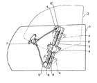
自動車ドアのウインドガラスを開閉するウインドレギュレータにあっては、モータを用いたウインドレギュレータがある。図5、図6を用いて説明する。
図5において、ドア本体1内には、ウインドガラス2の開閉方向に沿ったガイド3が設けられている。このガイド3には、ウインドガラス2が取り付けられたキャリアプレート4が移動可能に係合している。ガイド3はその上下両端のブラケット5,5を介してドア本体1に取り付けられており、各ブラケット5にはプーリ6,6’が設けられている。また、ドア本体1には、ケーブル巻取り機構を駆動する駆動源としてのモータ7が設けられている。
As a window regulator for opening and closing a window glass of an automobile door, there is a window regulator using a motor. This will be described with reference to FIGS.
In FIG. 5, a
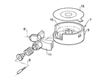
ここで、ケーブル巻き取り機構を説明する。
図6に示すように、モータ7によって回転駆動されるドラム10には、ワイヤが巻回されている。
Here, the cable winding mechanism will be described.
As shown in FIG. 6, a wire is wound around a
ドラム10は円柱状で、その周面には螺旋状の溝が形成されている。一方の端面(本例では下面)の中心には、モータ7の断面形状が矩形の出力軸に係合する角穴が設けられている。ドラム10の一方の端面には、第1のケーブル8の一端部が係止され、第1のケーブル8の中間部がドラム10の一方の端面側からドラム10の溝に沿って巻回され、ドラム10が一方の方向に回転すると、ドラム10から繰り出されるようになっている。ドラム10の他方の端面には、第2のケーブル8’の一端部が係止され、第2のケーブル8’の中間部がドラム10の他方の端面側からドラム10の溝に沿って巻回され、ドラム10が一方の方向に回転すると、ドラム10に巻き取られるようになっている。第1のケーブル8,第2のケーブル8’の他端部側は交差し、ケーブルガイド部材11によって案内されるようになっている。モータ7側には、底部にはモータ7の駆動軸が設けられ、周面部にケーブルガイド部材11が取り付けられ、ケーブルガイド部材11以外の周面部では、モータ7に係合したドラム10の周面を覆い、第1,第2のケーブル8,8’がドラム10の溝から外れるのを防止する一方の面が開放面となった有底円筒状のドラムハウジング9が設けられている。ドラムハウジング9の開放面は、ドラムカバー15によって覆われるようになっている。
The
図5に示すように、そして、ドラム10を出た第1のケーブル8は、プーリ6を介してキャリアプレート4に接続されている。また、ドラム10を出た第2のケーブル8’は、プーリ6’を介してキャリアプレート4に接続されている。よって、モータ7を駆動すると、第1のケーブル8、第2のケーブル8’が進退し、キャリアプレート4がガイド3に沿って移動し、ウインドガラス2が開閉する(特許文献1参照)。
As shown in FIG. 5, the
ここで、このような構成のケーブル巻き取り機構の組み付け方法を説明する。
最初に、ドラム10の一方の端面に、第1のケーブル8の一端部を係止させ、専用のケーブル巻き取り装置にドラム10をセットし、中間部をドラム10の一方の端面側からドラム10の溝に沿って巻回する。次に、ドラム10の他方の端面に、第2のケーブル8’の一端部を係止させ、中間部をドラム10の他方の端面側からドラム10の溝に沿って巻回する。
Here, a method of assembling the cable winding mechanism having such a configuration will be described.
First, one end portion of the
次に、専用のケーブル巻き取り装置にセットされたドラム10の角穴にモータ7の駆動軸を係合させ、専用のケーブル巻き取り装置より第1のケーブル8及び第2のケーブル8’とが巻回されたドラム10を取り外して、モータ7側に移動させた後に、ケーブルガイド部材11を取り付け、最後に、ドラムカバー15を取り付ける。
特許文献1に記載されたケーブル巻き取り機構を組付ける際には、専用のケーブル巻き取り装置にドラム10をセットし、ドラム10に第1のケーブル8及び第2のケーブル8’を巻回し、専用のケーブル巻き取り装置にセットされたドラム10の角穴にモータ7の駆動軸に係合させ、専用のケーブル巻き取り装置より第1のケーブル8及び第2のケーブル8’が巻回されたドラム10を取り外して、モータ7側に移動させる手間が必要である。また、専用のケーブル巻き取り装置が必要である。
When assembling the cable winding mechanism described in
よって、製造工数が多く、製造コストが高いという問題点がある。
本発明は、上記問題点に鑑みてなされたもので、その課題は、製造工数を削減でき、製造コストも低減できるケーブル巻き取り機構の組付け方法及びケーブル巻き取り機構を提供することにある。
Therefore, there are problems that the number of manufacturing steps is large and the manufacturing cost is high.
The present invention has been made in view of the above problems, and an object of the present invention is to provide a cable winding mechanism assembling method and a cable winding mechanism that can reduce the number of manufacturing steps and the manufacturing cost.
請求項1に係る発明は、周面に螺旋状の溝が形成され、一方の端面の中心に被係合部が設けられた円柱状のドラムと、該ドラムの一方の端面に一端部が係止され、中間部が前記ドラムの一方の端面側から前記ドラムの溝に沿って巻回され、前記ドラムが一方の方向に回転すると、前記ドラムから繰り出される第1のケーブルと、前記ドラムの他方の端面に一端部が係止され、中間部が前記ドラムの他方の端面側から前記ドラムの溝に沿って巻回され、前記ドラムが一方の方向に回転すると、前記ドラムに巻き取られる第2のケーブルと、前記ドラムの被係合部に係脱可能な係合部を有し、係合した前記ドラムを回転駆動する駆動源と、該駆動源側に設けられ、一方の面が開放面となった有底円筒状で、底部には前記駆動源の係合部が設けられ、前記駆動源に係合した前記ドラムの周面を覆い、前記第1,第2のケーブルが前記ドラムの溝から外れるのを防止する周面部を有するドラムハウジングと、該ドラムハウジングの周面部に形成された切り欠き部に設けられ、前記第1,第2のケーブルの他端部側を案内するケーブルガイド部材と、前記ドラムハウジングの開放面を覆うドラムカバーと、からなるケーブル巻き取り機構の組み付け方法において、前記ドラムの被係合部が前記駆動源の係合部に係合すると、前記ドラムの周面に形成された溝のうち、他方の端面側の溝の少なくとも一巻き分が前記ドラムハウジングから外部に露出するように前記ドラム、前記ドラムハウジングの高さを設定し、前記ケーブルガイド部材を、前記第1のケーブルを案内する第1のケーブルガイド部材と、前記第2のケーブルを案内する第2のケーブルガイド部材とで構成し、前記ドラムカバーは、前記ドラムハウジングの開放面を覆う本体部と、前記ドラムハウジングから外部に露出した前記ドラムの周面を覆うドラム周面対向部とを有し、前記第1のケーブルに前記第1のケーブルガイド部材、前記第2のケーブルに前記第2のケーブルガイド部材を取り付け、前記ドラムの一方の端面に前記第1のケーブルの一端部側を係止し、前記ドラムハウジングの開放面から前記ドラムを挿入し、前記ドラムの一方の端面側の被係合部を前記駆動源の係合部に係合させ、前記第1のケーブルガイド部材を前記ドラムハウジングの切り欠き部に設け、前記駆動源を駆動して、前記ドラムを一方の方向に回転させて、前記第1のケーブルを前記ドラムに巻回し、前記ドラムの他方の端面に前記第2のケーブルの一端部側を係止すると共に、前記ドラムハウジングから外部に露出したドラムの周面の溝に前記第2のケーブルを巻き付け、前記第2のケーブルガイド部材を前記ドラムハウジングの切り欠き部に設け、前記ドラムカバーで前記ドラムハウジングの開放面を覆うことを特徴とするケーブル巻き取り機構の組付け方法である。 According to a first aspect of the present invention, there is provided a cylindrical drum in which a spiral groove is formed on the peripheral surface and an engaged portion is provided at the center of one end surface, and one end portion is engaged with one end surface of the drum. The intermediate portion is wound along the groove of the drum from one end face side of the drum, and when the drum rotates in one direction, the first cable fed out from the drum and the other end of the drum One end is locked to the end surface of the drum, the intermediate portion is wound along the groove of the drum from the other end surface side of the drum, and when the drum rotates in one direction, the second portion is wound around the drum. And a drive source that rotationally drives the engaged drum, and one surface is an open surface. a bottomed cylindrical shape which becomes, the engaging portion of the driving source is provided at the bottom A drum housing having a peripheral surface portion that covers the peripheral surface of the drum engaged with the drive source and prevents the first and second cables from being detached from the groove of the drum, and formed on the peripheral surface portion of the drum housing Assembling a cable winding mechanism that is provided in the cut-out portion and includes a cable guide member that guides the other end side of the first and second cables, and a drum cover that covers the open surface of the drum housing. In the method, when the engaged portion of the drum is engaged with the engaging portion of the drive source, at least one turn of the groove on the other end surface side among the grooves formed on the peripheral surface of the drum is the drum. The height of the drum and the drum housing is set so as to be exposed to the outside from the housing, and the cable guide member guides the first cable. And a second cable guide member that guides the second cable, and the drum cover includes a main body that covers an open surface of the drum housing, and a drum that is exposed to the outside from the drum housing. A drum peripheral surface facing portion that covers the peripheral surface, the first cable guide member is attached to the first cable, the second cable guide member is attached to the second cable, and one end surface of the drum The one end side of the first cable is locked, the drum is inserted from the open surface of the drum housing, and the engaged portion on one end surface side of the drum is engaged with the engaging portion of the drive source. The first cable guide member is provided in the cutout portion of the drum housing, the drive source is driven, the drum is rotated in one direction, and the first cable is connected to the driver. The second cable is locked to the other end surface of the drum, and the second cable is wound around the groove on the peripheral surface of the drum exposed to the outside from the drum housing. In the assembling method of the cable winding mechanism, the second cable guide member is provided in a notch portion of the drum housing, and the drum cover covers an open surface of the drum housing.
請求項2に係る発明は、周面に螺旋状の溝が形成され、一方の端面の中心に被係合部が設けられた円柱状のドラムと、該ドラムの一方の端面に一端部が係止され、中間部が前記ドラムの一方の端面側から前記ドラムの溝に沿って巻回され、前記ドラムが一方の方向に回転すると、前記ドラムから繰り出される第1のケーブルと、前記ドラムの他方の端面に一端部が係止され、中間部が前記ドラムの他方の端面側から前記ドラムの溝に沿って巻回され、前記ドラムが一方の方向に回転すると、前記ドラムに巻き取られる第2のケーブルと、前記ドラムの被係合部に係脱可能な係合部を有し、係合した前記ドラムを回転駆動する駆動源と、該駆動源側に設けられ、一方の面が開放面となった有底円筒状で、底部には前記駆動源の係合部が設けられ、前記駆動源に係合した前記ドラムの周面を覆い、前記第1,第2のケーブルが前記ドラムの溝から外れるのを防止する周面部を有するドラムハウジングと、該ドラムハウジングの周面部に形成された切り欠き部に設けられ、前記第1,第2のケーブルの他端部側を案内するケーブルガイド部材と、前記ドラムハウジングの開放面を覆うドラムカバーと、からなるケーブル巻き取り機構において、前記ドラムの被係合部が前記駆動源の係合部に係合すると、前記ドラムの周面に形成された溝のうち、他方の端面側の溝の少なくとも一巻き分が前記ドラムハウジングから外部に露出するように前記ドラム、前記ドラムハウジングの高さを設定し、前記ケーブルガイド部材を、前記第1のケーブルを案内する第1のケーブルガイド部材と、前記第2のケーブルを案内する第2のケーブルガイド部材とで構成し、前記ドラムカバーは、前記ドラムハウジングの開放面を覆う本体部と、前記ドラムハウジングから外部に露出した前記ドラムの周面を覆うドラム周面対向部とを有したことを特徴とするケーブル巻き取り機構である。 According to a second aspect of the present invention, there is provided a cylindrical drum in which a spiral groove is formed on the peripheral surface and an engaged portion is provided at the center of one end surface, and one end portion of the drum is engaged with one end surface. The intermediate portion is wound along the groove of the drum from one end face side of the drum, and when the drum rotates in one direction, the first cable fed out from the drum and the other end of the drum One end is locked to the end surface of the drum, the intermediate portion is wound along the groove of the drum from the other end surface side of the drum, and when the drum rotates in one direction, the second portion is wound around the drum. And a drive source that rotationally drives the engaged drum, and one surface is an open surface. a bottomed cylindrical shape which becomes, the engaging portion of the driving source is provided at the bottom A drum housing having a peripheral surface portion that covers the peripheral surface of the drum engaged with the drive source and prevents the first and second cables from being detached from the groove of the drum, and formed on the peripheral surface portion of the drum housing In a cable winding mechanism comprising a cable guide member that is provided in the cut-out portion and that guides the other end side of the first and second cables, and a drum cover that covers an open surface of the drum housing, When the engaged portion of the drum engages with the engaging portion of the drive source, at least one turn of the groove on the other end surface side out of the groove formed on the peripheral surface of the drum is external to the drum housing. The height of the drum and the drum housing is set so as to be exposed to the cable, and the cable guide member is guided to the first cable by the first cable guide member and the first cable guide member. A second cable guide member for guiding the cable, and the drum cover includes a main body that covers an open surface of the drum housing, and a drum periphery that covers a peripheral surface of the drum exposed to the outside from the drum housing. A cable winding mechanism having a surface facing portion.
請求項1に係る発明によれば、前記ドラムの被係合部が前記駆動源の係合部に係合すると、前記ドラムの周面に形成された溝のうち、他方の端面側の溝の少なくとも一巻き分が前記ドラムハウジングから外部に露出するように前記ドラム、前記ドラムハウジングの高さを設定し、前記ケーブルガイド部材を、前記第1のケーブルを案内する第1のケーブルガイド部材と、前記第2のケーブルを案内する第2のケーブルガイド部材とで構成し、前記ドラムカバーは、前記ドラムハウジングの開放面を覆う本体部と、前記ドラムハウジングから外部に露出した前記ドラムの周面を覆うドラム周面対向部とを有し、前記第1のケーブルに前記第1のケーブルガイド部材、前記第2のケーブルに前記第2のケーブルガイド部材を取り付け、前記ドラムの一方の端面に前記第1のケーブルの一端部側を係止し、前記ドラムハウジングの開放面から前記ドラムを挿入し、前記ドラムの一方の端面側の被係合部を前記駆動源の係合部に係合させ、前記第1のケーブルガイド部材を前記ドラムハウジングの切り欠き部に設け、前記駆動源を駆動して、前記ドラムを一方の方向に回転させて、前記第1のケーブルを前記ドラムに巻回し、前記ドラムの他方の端面に前記第2のケーブルの一端部側を係止すると共に、前記ドラムハウジングから外部に露出したドラムの周面の溝に前記第2のケーブルを巻き付け、前記第2のケーブルガイド部材を前記ドラムハウジングの切り欠き部に設け、前記ドラムカバーで前記ドラムハウジングの開放面を覆うことにより、ケーブル巻き取り機構を組付ける際には、専用のケーブル巻き取り装置にドラムをセットし、ドラムに第1のケーブルを巻回し、専用のケーブル巻き取り装置にセットされたドラムの角穴にモータの駆動軸に係合させ、専用のケーブル巻き取り装置より第1のケーブルが巻回されたドラムを取り外して、モータ7側に移動させる手間が不要となる。また、専用のケーブル巻き取り装置が不要となる。よって、製造工数を削減でき、製造コストも低減できる。
According to the first aspect of the present invention, when the engaged portion of the drum is engaged with the engaging portion of the drive source, the groove on the other end surface side among the grooves formed on the peripheral surface of the drum is arranged. The height of the drum and the drum housing is set so that at least one turn is exposed from the drum housing, the cable guide member is guided to the first cable, and the first cable guide member is guided to the first cable. The drum cover includes a main body portion that covers an open surface of the drum housing, and a peripheral surface of the drum that is exposed to the outside from the drum housing. A drum peripheral surface facing portion for covering, the first cable guide member being attached to the first cable, and the second cable guide member being attached to the second cable, One end surface of the first cable is locked to one end surface, the drum is inserted from the open surface of the drum housing, and the engaged portion on one end surface side of the drum is engaged with the drive source. The first cable guide member is provided in the notch portion of the drum housing, the drive source is driven, the drum is rotated in one direction, and the first cable is Winding around a drum, locking one end of the second cable to the other end surface of the drum, and winding the second cable in a groove on the peripheral surface of the drum exposed to the outside from the drum housing, When assembling the cable winding mechanism by providing the second cable guide member in the cutout portion of the drum housing and covering the open surface of the drum housing with the drum cover, Set the drum on the cable take-up device, wind the first cable on the drum, engage the square shaft hole of the drum set on the special cable take-up device with the drive shaft of the motor, and wind the dedicated cable There is no need to remove the drum around which the first cable is wound from the take-off device and move it to the
請求項2に係る発明によれば、前記ドラムの被係合部が前記駆動源の係合部に係合すると、前記ドラムの周面に形成された溝のうち、他方の端面側の溝の少なくとも一巻き分が前記ドラムハウジングから外部に露出するように前記ドラム、前記ドラムハウジングの高さを設定し、前記ケーブルガイド部材を、前記第1のケーブルを案内する第1のケーブルガイド部材と、前記第2のケーブルを案内する第2のケーブルガイド部材とで構成し、
前記ドラムカバーは、前記ドラムハウジングの開放面を覆う本体部と、前記ドラムハウジングから外部に露出した前記ドラムの周面を覆うドラム周面対向部とを有したことにより、組み付けの際に、前記第1のケーブルに前記第1のケーブルガイド部材、前記第2のケーブルに前記第2のケーブルガイド部材を取り付け、前記ドラムの一方の端面に前記第1のケーブルの一端部側を係止すると共に、前記第1のケーブルガイド部材を前記ドラムハウジングの切り欠き部に設け、前記ドラムハウジングの開放面から前記ドラムを挿入し、前記ドラムの一方の端面側の被係合部を前記駆動源の係合部に係合させ、前記第1のケーブルガイド部材を前記ドラムハウジングに取り付け、前記駆動源を駆動して、前記ドラムを一方の方向に回転させて、前記第1のケーブルを前記ドラムに巻回し、前記ドラムの他方の端面に前記第2のケーブルの一端部側を係止すると共に、前記ドラムハウジングから外部に露出したドラムの周面の溝に前記第2のケーブルを巻き付け、前記第2のケーブルガイド部材を前記ドラムハウジングの切り欠き部に設け、前記ドラムカバーで前記ドラムハウジングの開放面を覆えば、ケーブル巻き取り機構を組付ける際には、専用のケーブル巻き取り装置にドラムをセットし、ドラムに第1のケーブルを巻回し、専用のケーブル巻き取り装置にセットされたドラムの角穴にモータの駆動軸に係合させ、専用のケーブル巻き取り装置より第1のケーブルが巻回されたドラムを取り外して、モータ7側に移動させる手間が不要となる。また、専用のケーブル巻き取り装置が不要となる。よって、製造工数を削減でき、製造コストも低減できる。
According to the second aspect of the present invention, when the engaged portion of the drum is engaged with the engaging portion of the driving source, the groove on the other end surface side among the grooves formed on the peripheral surface of the drum is formed. The height of the drum and the drum housing is set so that at least one turn is exposed from the drum housing, the cable guide member is guided to the first cable, and the first cable guide member is guided to the first cable. A second cable guide member for guiding the second cable;
The drum cover has a main body portion covering the open surface of the drum housing and a drum peripheral surface facing portion covering the peripheral surface of the drum exposed to the outside from the drum housing. The first cable guide member is attached to the first cable, the second cable guide member is attached to the second cable, and one end of the first cable is locked to one end face of the drum. The first cable guide member is provided in the cutout portion of the drum housing, the drum is inserted from the open surface of the drum housing, and the engaged portion on one end surface side of the drum is engaged with the drive source. Engaging the joint, attaching the first cable guide member to the drum housing, driving the drive source, rotating the drum in one direction, The first cable is wound around the drum, the one end side of the second cable is locked to the other end surface of the drum, and the groove on the peripheral surface of the drum exposed to the outside from the drum housing When assembling the cable winding mechanism, the second cable is wound, the second cable guide member is provided in the notch portion of the drum housing, and the drum cover covers the open surface of the drum housing. Set the drum on the dedicated cable winding device, wind the first cable around the drum, engage the square shaft hole of the drum set on the dedicated cable winding device with the drive shaft of the motor, and wind the dedicated cable There is no need to remove the drum around which the first cable is wound from the take-off device and move it to the
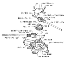
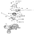
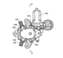
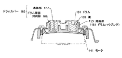
図1−図4を用いて、ウインドレギュレータに用いられる本形態例のケーブル巻き取り機構の構成を説明する。図1は本形態例のケーブル巻き取り機構の分解斜視図、図2は図1の分解斜視図を下方から見た分解斜視図、図3は組み付け後における図1の上面図、図4は図3の切断線A−Aでの断面図である。 The configuration of the cable winding mechanism of this embodiment used in the window regulator will be described with reference to FIGS. 1 is an exploded perspective view of the cable winding mechanism of this embodiment, FIG. 2 is an exploded perspective view of the exploded perspective view of FIG. 1 viewed from below, FIG. 3 is a top view of FIG. 1 after assembly, and FIG. 3 is a cross-sectional view taken along section line AA of FIG.
図1、図2に示すように、円柱状のドラム101の周面には、螺旋状の溝103が形成されている。図2に示すように、ドラム101の下面(一方の端面)105の中心には、被係合部としての断面形状が非円形の角穴107が形成されている。
As shown in FIGS. 1 and 2, a
図1に示すように、ドラム101の上面(他方の端面)109には、ケーブルの先端に設けられたエンド部材が係合可能で、係合したケーブルをドラム101の周面の溝まで案内するエンド部材係止部111が形成されている。図2に示すように、ドラム101の下面105には、ケーブルの先端に設けられたエンド部材が係合可能で、係合したケーブルをドラム101の周面の溝まで案内するエンド部材係止部113が形成されている。
As shown in FIG. 1, the end member provided at the tip of the cable can be engaged with the upper surface (the other end surface) 109 of the drum 101, and the engaged cable is guided to the groove on the peripheral surface of the drum 101. An end member locking portion 111 is formed. As shown in FIG. 2, an end member locking portion that can engage an end member provided at the tip of the cable with the
図2に示すように、第1のケーブル121の先端にはエンド部材123が取り付けられ、このエンド部材123は、ドラム101の下面105のエンド部材係止部113に係止され、ドラム101の溝103に沿って巻回され、ドラム101が一方の方向(図2において、矢印II方向)に回転すると、第1のケーブル121は、ドラム101から繰り出されるようになっている。
As shown in FIG. 2, an
また、図1に示すように、第2のケーブル131の先端にはエンド部材133が取り付けられ、このエンド部材133は、ドラム101の上面109のエンド部材係止部111に係止され、ドラム101の溝103に沿って巻回され、ドラム101が一方の方向(図1において、矢印I方向)に回転すると、第2のケーブル131は、ドラム101に巻き取られるようになっている。
As shown in FIG. 1, an
図1に示すように、駆動源は減速機構が一体化したモータ141でなり、その出力軸143は、断面形状が非円形の矩形となっている。そして、この出力軸143には、ドラム101の下面(一方の端面)105の中心に形成された角穴107が係脱可能となっている。ドラム101の角穴107が、モータ141の出力軸に係合することにより、ドラム101はモータ141により回転駆動される。
As shown in FIG. 1, the drive source is a
また、図1、図2に示すように、第1のケーブル121,第2のケーブル131の中間部は、アウタケーブル125,135内を挿通している。アウタケーブル125,135の一方の端部には、円板状のケーブルエンド部材125a,135aが取り付けられている。
As shown in FIGS. 1 and 2, the intermediate portions of the
モータ141には、第1のケーブルガイド部材129,第2のケーブルガイド部材139が取り付けられる。第1のケーブルガイド部材129、第2のケーブルガイド部材139は、第1のケーブル121、第2のケーブル131が挿通可能な溝を有している。第1のケーブル121、第2のケーブル131が溝を挿通することにより、第1のケーブル121はドラム101の下面105に、第2のケーブル131はドラム101の上面109にそれぞれ案内されるようになっている。
A first
また、モータ141に取り付けられた第1のケーブルガイド部材129と、第1のケーブル121のアウタケーブル125のエンド部材125aとの間には、スプリング127が設けられ、アウタケーブル125を軸方向に付勢している。また、アウタケーブル125の他方の側は固定されており、第1のケーブル121にたるみが発生すると、スプリング127の付勢力により、アウタケーブル125が押し出され、第1のケーブル121の経路が伸びて、第1のケーブル121のたるみが吸収される。
Also, a
同様に、モータ141に取り付けられた第2のケーブルガイド部材139と、第2のケーブル131のアウタケーブル135のエンド部材135aとの間には、スプリング137が設けられ、アウタケーブル135を軸方向に付勢している。また、アウタケーブル135の他方の側は固定されており、第2のケーブル131にたるみが発生すると、スプリング137の付勢力により、アウタケーブル135が押し出され、第2のケーブル131の経路が伸びて、第2のケーブル131のたるみが吸収される。
Similarly, a
図1に示すように、モータ141には、有底円筒状のドラムハウジング151が設けられる。このドラムハウジング151の底部にはモータ141の出力軸143が設けられる。ドラムハウジング151の周面部153には、第1のケーブルガイド部材129、第2のケーブルガイド部材139が設けられる切り欠き部155が形成されている。切り欠き部155以外の周面部153は、モータ141に係合したドラム101の周面を覆い、第1,第2のケーブル121,131がドラム101の溝103から外れるのを防止するようになっている。
As shown in FIG. 1, the
図1、図2に示すように、ドラムハウジング151の開放面は、ねじ161でモータ141に取り付けられるドラムカバー163で覆われる。
そして、本形態例では、図4に示すように、ドラム101の角穴107がモータ141の出力軸143に係合すると、ドラム101の周面に形成された溝103のうち、上面(他方の面)109側の溝の少なくとも一巻き分がドラムハウジング151から外部に露出するように、ドラム101、ドラムハウジング151の周面部153の高さを設定している。また、ドラムカバー163は、ドラムハウジング151の開放面を覆う本体部165と、ドラムハウジング151から外部に露出したドラム101の周面を覆うドラム周面対向部167とを有している。
As shown in FIGS. 1 and 2, the open surface of the drum housing 151 is covered with a drum cover 163 attached to the
In this embodiment, as shown in FIG. 4, when the square hole 107 of the drum 101 is engaged with the output shaft 143 of the
次に、上記構成のケーブル巻き取り機構の組付け方法を説明する。
第1のケーブル121に第1のケーブルガイド部材129を取り付け、第2のケーブル131に第2のケーブルガイド部材139を取り付ける(第1工程)。
Next, a method for assembling the cable winding mechanism having the above configuration will be described.
The first
ドラム101の下面(一方の端面)105のエンド部材係止部113に第1のケーブル121のエンド部材123を係止する(第2工程)。
ドラムハウジング151の開放面からドラム101を挿入し、前記ドラム101の下面(一方の端面)の角穴107をモータの出力軸143に係合させる(第3工程)。
The
The drum 101 is inserted from the open surface of the drum housing 151, and the square hole 107 on the lower surface (one end surface) of the drum 101 is engaged with the output shaft 143 of the motor (third step).
第1のケーブルガイド部材129をドラムハウジング151の切り欠き部155に設ける(第4工程)。
モータ141を駆動して、ドラム101を一方の方向に回転させて、第1のケーブル121をドラム101に巻回する(第5工程)。
The first
The
ドラム101の上面(他方の端面)109のエンド部材係止部111に第2のケーブル131のエンド部材133を係止し、ドラムハウジング151から外部に露出したドラム101の周面の溝に第2のケーブル131を巻き付ける(第6工程)。
The
第2のケーブルガイド部材139をドラムハウジング151の切り欠き部155に設ける(第7工程)。
ねじ161を用いてドラムカバー163を取り付け、ドラムハウジング151の開放面を覆う(第8工程)。
The second
The drum cover 163 is attached using the
このような構成によれば、ケーブル巻き取り機構を組付ける際には、専用のケーブル巻き取り装置にドラムをセットし、ドラムに第1のケーブルを巻回し、専用のケーブル巻き取り装置にセットされたドラムの角穴にモータの駆動軸を係合させ、専用のケーブル巻き取り装置より第1のケーブル121及び第2のケーブル131が巻回されたドラム101を取り外して、モータ141側に移動させる手間が不要となる。また、専用のケーブル巻き取り装置が不要となる。よって、製造工数を削減でき、製造コストも低減できる。
According to such a configuration, when assembling the cable winding mechanism, the drum is set in the dedicated cable winding device, the first cable is wound around the drum, and the cable winding device is set in the dedicated cable winding device. The drive shaft of the motor is engaged with the square hole of the drum, and the drum 101 around which the
101 ドラム
103 溝
121 第1のケーブル
129 第1のケーブルガイド部材
131 第2のケーブル
139 第2のケーブルガイド部材
151 ドラムハウジング
163 ドラムカバー
101
Claims (2)
該ドラムの一方の端面に一端部が係止され、中間部が前記ドラムの一方の端面側から前記ドラムの溝に沿って巻回され、前記ドラムが一方の方向に回転すると、前記ドラムから繰り出される第1のケーブルと、
前記ドラムの他方の端面に一端部が係止され、中間部が前記ドラムの他方の端面側から前記ドラムの溝に沿って巻回され、前記ドラムが一方の方向に回転すると、前記ドラムに巻き取られる第2のケーブルと、
前記ドラムの被係合部に係脱可能な係合部を有し、係合した前記ドラムを回転駆動する駆動源と、
該駆動源側に設けられ、一方の面が開放面となった有底円筒状で、底部には前記駆動源の係合部が設けられ、前記駆動源に係合した前記ドラムの周面を覆い、前記第1,第2のケーブルが前記ドラムの溝から外れるのを防止する周面部を有するドラムハウジングと、
該ドラムハウジングの周面部に形成された切り欠き部に設けられ、前記第1,第2のケーブルの他端部側を案内するケーブルガイド部材と、
前記ドラムハウジングの開放面を覆うドラムカバーと、
からなるケーブル巻き取り機構の組み付け方法において、
前記ドラムの被係合部が前記駆動源の係合部に係合すると、前記ドラムの周面に形成された溝のうち、他方の端面側の溝の少なくとも一巻き分が前記ドラムハウジングから外部に露出するように前記ドラム、前記ドラムハウジングの高さを設定し、
前記ケーブルガイド部材を、前記第1のケーブルを案内する第1のケーブルガイド部材と、前記第2のケーブルを案内する第2のケーブルガイド部材とで構成し、
前記ドラムカバーは、前記ドラムハウジングの開放面を覆う本体部と、前記ドラムハウジングから外部に露出した前記ドラムの周面を覆うドラム周面対向部とを有し、
前記第1のケーブルに前記第1のケーブルガイド部材、前記第2のケーブルに前記第2のケーブルガイド部材を取り付け、
前記ドラムの一方の端面に前記第1のケーブルの一端部側を係止し、
前記ドラムハウジングの開放面から前記ドラムを挿入し、前記ドラムの一方の端面側の被係合部を前記駆動源の係合部に係合させ、
前記第1のケーブルガイド部材を前記ドラムハウジングの切り欠き部に設け、
前記駆動源を駆動して、前記ドラムを一方の方向に回転させて、前記第1のケーブルを前記ドラムに巻回し、
前記ドラムの他方の端面に前記第2のケーブルの一端部側を係止すると共に、前記ドラムハウジングから外部に露出したドラムの周面の溝に前記第2のケーブルを巻き付け、
前記第2のケーブルガイド部材を前記ドラムハウジングの切り欠き部に設け、
前記ドラムカバーで前記ドラムハウジングの開放面を覆うことを特徴とするケーブル巻き取り機構の組付け方法。 A cylindrical drum in which a spiral groove is formed on the peripheral surface, and an engaged portion is provided at the center of one end surface;
One end of the drum is locked to one end surface, the intermediate portion is wound along the groove of the drum from one end surface side of the drum, and when the drum rotates in one direction, the drum is unwound from the drum. A first cable
One end is locked to the other end surface of the drum, the intermediate portion is wound along the groove of the drum from the other end surface side of the drum, and when the drum rotates in one direction, the drum is wound around the drum. A second cable to be taken;
A drive source that has an engaging portion that can be engaged and disengaged with the engaged portion of the drum, and that rotationally drives the engaged drum;
Provided on the drive source side, and has a bottomed cylindrical shape with one surface being an open surface, and an engagement portion of the drive source is provided at the bottom, and the peripheral surface of the drum engaged with the drive source is A drum housing having a peripheral surface portion for covering and preventing the first and second cables from coming off the groove of the drum;
A cable guide member provided in a notch formed in the peripheral surface portion of the drum housing and guiding the other end side of the first and second cables;
A drum cover covering an open surface of the drum housing;
In the assembly method of the cable winding mechanism consisting of
When the engaged portion of the drum engages with the engaging portion of the drive source, at least one turn of the groove on the other end surface side out of the groove formed on the peripheral surface of the drum is external to the drum housing. Set the height of the drum and the drum housing to be exposed to the
The cable guide member includes a first cable guide member that guides the first cable, and a second cable guide member that guides the second cable,
The drum cover includes a main body portion that covers an open surface of the drum housing, and a drum peripheral surface facing portion that covers a peripheral surface of the drum exposed to the outside from the drum housing,
Attaching the first cable guide member to the first cable and the second cable guide member to the second cable;
Lock one end of the first cable to one end surface of the drum,
The drum is inserted from the open surface of the drum housing, and the engaged portion on one end surface side of the drum is engaged with the engaging portion of the drive source,
Providing the first cable guide member in a notch of the drum housing;
Drive the drive source, rotate the drum in one direction, wind the first cable around the drum,
The one end side of the second cable is locked to the other end surface of the drum, and the second cable is wound around the groove on the peripheral surface of the drum exposed to the outside from the drum housing,
Providing the second cable guide member in a notch of the drum housing;
An assembly method for a cable winding mechanism, wherein the drum cover covers an open surface of the drum housing.
該ドラムの一方の端面に一端部が係止され、中間部が前記ドラムの一方の端面側から前記ドラムの溝に沿って巻回され、前記ドラムが一方の方向に回転すると、前記ドラムから繰り出される第1のケーブルと、
前記ドラムの他方の端面に一端部が係止され、中間部が前記ドラムの他方の端面側から前記ドラムの溝に沿って巻回され、前記ドラムが一方の方向に回転すると、前記ドラムに巻き取られる第2のケーブルと、
前記ドラムの被係合部に係脱可能な係合部を有し、係合した前記ドラムを回転駆動する駆動源と、
該駆動源側に設けられ、一方の面が開放面となった有底円筒状で、底部には前記駆動源の係合部が設けられ、前記駆動源に係合した前記ドラムの周面を覆い、前記第1,第2のケーブルが前記ドラムの溝から外れるのを防止する周面部を有するドラムハウジングと、
該ドラムハウジングの周面部に形成された切り欠き部に設けられ、前記第1,第2のケーブルの他端部側を案内するケーブルガイド部材と、
前記ドラムハウジングの開放面を覆うドラムカバーと、
からなるケーブル巻き取り機構において、
前記ドラムの被係合部が前記駆動源の係合部に係合すると、前記ドラムの周面に形成された溝のうち、他方の端面側の溝の少なくとも一巻き分が前記ドラムハウジングから外部に露出するように前記ドラム、前記ドラムハウジングの高さを設定し、
前記ケーブルガイド部材を、前記第1のケーブルを案内する第1のケーブルガイド部材と、前記第2のケーブルを案内する第2のケーブルガイド部材とで構成し、
前記ドラムカバーは、前記ドラムハウジングの開放面を覆う本体部と、前記ドラムハウジングから外部に露出した前記ドラムの周面を覆うドラム周面対向部とを有したことを特徴とするケーブル巻き取り機構。 A cylindrical drum in which a spiral groove is formed on the peripheral surface, and an engaged portion is provided at the center of one end surface;
One end of the drum is locked to one end surface, the intermediate portion is wound along the groove of the drum from one end surface side of the drum, and when the drum rotates in one direction, the drum is unwound from the drum. A first cable
One end is locked to the other end surface of the drum, the intermediate portion is wound along the groove of the drum from the other end surface side of the drum, and when the drum rotates in one direction, the drum is wound around the drum. A second cable to be taken;
A drive source that has an engaging portion that can be engaged and disengaged with the engaged portion of the drum, and that rotationally drives the engaged drum;
Provided on the drive source side, and has a bottomed cylindrical shape with one surface being an open surface, and an engagement portion of the drive source is provided at the bottom, and the peripheral surface of the drum engaged with the drive source is A drum housing having a peripheral surface portion for covering and preventing the first and second cables from coming off the groove of the drum;
A cable guide member provided in a notch formed in the peripheral surface portion of the drum housing and guiding the other end side of the first and second cables;
A drum cover covering an open surface of the drum housing;
In the cable winding mechanism consisting of
When the engaged portion of the drum engages with the engaging portion of the drive source, at least one turn of the groove on the other end surface side out of the groove formed on the peripheral surface of the drum is external to the drum housing. Set the height of the drum and the drum housing to be exposed to the
The cable guide member includes a first cable guide member that guides the first cable, and a second cable guide member that guides the second cable,
The drum cover includes a main body portion that covers an open surface of the drum housing, and a drum circumferential surface facing portion that covers a circumferential surface of the drum exposed to the outside from the drum housing. .
Priority Applications (1)
| Application Number | Priority Date | Filing Date | Title |
|---|---|---|---|
| JP2008024793A JP5154965B2 (en) | 2008-02-05 | 2008-02-05 | Assembly method of cable winding mechanism and cable winding mechanism |
Applications Claiming Priority (1)
| Application Number | Priority Date | Filing Date | Title |
|---|---|---|---|
| JP2008024793A JP5154965B2 (en) | 2008-02-05 | 2008-02-05 | Assembly method of cable winding mechanism and cable winding mechanism |
Publications (2)
| Publication Number | Publication Date |
|---|---|
| JP2009185475A JP2009185475A (en) | 2009-08-20 |
| JP5154965B2 true JP5154965B2 (en) | 2013-02-27 |
Family
ID=41068983
Family Applications (1)
| Application Number | Title | Priority Date | Filing Date |
|---|---|---|---|
| JP2008024793A Expired - Fee Related JP5154965B2 (en) | 2008-02-05 | 2008-02-05 | Assembly method of cable winding mechanism and cable winding mechanism |
Country Status (1)
| Country | Link |
|---|---|
| JP (1) | JP5154965B2 (en) |
Families Citing this family (3)
| Publication number | Priority date | Publication date | Assignee | Title |
|---|---|---|---|---|
| JP5841754B2 (en) * | 2011-06-30 | 2016-01-13 | 株式会社ハイレックスコーポレーション | Window regulator |
| JP6345063B2 (en) | 2014-09-26 | 2018-06-20 | シロキ工業株式会社 | Vehicle window regulator and tilt suppression mechanism |
| US10385604B2 (en) * | 2015-04-14 | 2019-08-20 | Shiroki Corporation | Window regulator manufacturing method and tension applying method for drive wire |
Family Cites Families (3)
| Publication number | Priority date | Publication date | Assignee | Title |
|---|---|---|---|---|
| JP2521628Y2 (en) * | 1991-12-11 | 1996-12-25 | 日本ケーブル・システム株式会社 | Structure of drive unit for cable type wind regulator |
| JPH1113336A (en) * | 1997-06-20 | 1999-01-19 | Nippon Cable Syst Inc | Power window regulator |
| JP3560850B2 (en) * | 1999-06-03 | 2004-09-02 | 株式会社ミツバ | Cable drive |
-
2008
- 2008-02-05 JP JP2008024793A patent/JP5154965B2/en not_active Expired - Fee Related
Also Published As
| Publication number | Publication date |
|---|---|
| JP2009185475A (en) | 2009-08-20 |
Similar Documents
| Publication | Publication Date | Title |
|---|---|---|
| US6796085B2 (en) | Window regulator | |
| JP6374296B2 (en) | Guide rail fitting structure and window regulator | |
| US20090090065A1 (en) | Window Regulator | |
| US9957746B2 (en) | Motor unit, motor with speed reduction mechanism, and sliding door automatic opening/closing device | |
| JP5154965B2 (en) | Assembly method of cable winding mechanism and cable winding mechanism | |
| CN1325741C (en) | Drive device for wire-type window regulator | |
| JP2013249683A (en) | Method for fixing drive motor in window regulator, and the window regulator | |
| JP4746400B2 (en) | Wire winding device | |
| US20130133265A1 (en) | Window regulator | |
| US20070199246A1 (en) | Window regulator cable drum | |
| JP3178741B2 (en) | Wind regulator wire take-up device | |
| JP4354933B2 (en) | Window regulator and jig | |
| CN105143583B (en) | Window regulator | |
| JP3798646B2 (en) | Window regulator | |
| JP4213458B2 (en) | Wire type window regulator device | |
| JP2017040093A (en) | Manufacturing method of window regulator and window regulator | |
| JP2014091923A (en) | Wire driving device | |
| JP7710419B2 (en) | Object moving device and window regulator | |
| JP2009013669A (en) | Window regulator | |
| JP2001328434A (en) | Sun roof device | |
| JP2014177836A (en) | Window regulator | |
| JP3802364B2 (en) | Window regulator | |
| JP2003082926A (en) | Vehicle door opening and closing drive | |
| JP2007309453A (en) | Wire winding device | |
| JP6882952B2 (en) | Mobile device |
Legal Events
| Date | Code | Title | Description |
|---|---|---|---|
| A621 | Written request for application examination |
Free format text: JAPANESE INTERMEDIATE CODE: A621 Effective date: 20101004 |
|
| RD04 | Notification of resignation of power of attorney |
Free format text: JAPANESE INTERMEDIATE CODE: A7424 Effective date: 20111024 |
|
| A977 | Report on retrieval |
Free format text: JAPANESE INTERMEDIATE CODE: A971007 Effective date: 20120424 |
|
| A131 | Notification of reasons for refusal |
Free format text: JAPANESE INTERMEDIATE CODE: A131 Effective date: 20120523 |
|
| A521 | Request for written amendment filed |
Free format text: JAPANESE INTERMEDIATE CODE: A523 Effective date: 20120613 |
|
| TRDD | Decision of grant or rejection written | ||
| A01 | Written decision to grant a patent or to grant a registration (utility model) |
Free format text: JAPANESE INTERMEDIATE CODE: A01 Effective date: 20121204 |
|
| A61 | First payment of annual fees (during grant procedure) |
Free format text: JAPANESE INTERMEDIATE CODE: A61 Effective date: 20121206 |
|
| FPAY | Renewal fee payment (event date is renewal date of database) |
Free format text: PAYMENT UNTIL: 20151214 Year of fee payment: 3 |
|
| R150 | Certificate of patent or registration of utility model |
Ref document number: 5154965 Country of ref document: JP Free format text: JAPANESE INTERMEDIATE CODE: R150 Free format text: JAPANESE INTERMEDIATE CODE: R150 |
|
| R250 | Receipt of annual fees |
Free format text: JAPANESE INTERMEDIATE CODE: R250 |
|
| R250 | Receipt of annual fees |
Free format text: JAPANESE INTERMEDIATE CODE: R250 |
|
| R250 | Receipt of annual fees |
Free format text: JAPANESE INTERMEDIATE CODE: R250 |
|
| R250 | Receipt of annual fees |
Free format text: JAPANESE INTERMEDIATE CODE: R250 |
|
| LAPS | Cancellation because of no payment of annual fees |