JP5154943B2 - Placemat for interactive display table - Google Patents
Placemat for interactive display table Download PDFInfo
- Publication number
- JP5154943B2 JP5154943B2 JP2007542459A JP2007542459A JP5154943B2 JP 5154943 B2 JP5154943 B2 JP 5154943B2 JP 2007542459 A JP2007542459 A JP 2007542459A JP 2007542459 A JP2007542459 A JP 2007542459A JP 5154943 B2 JP5154943 B2 JP 5154943B2
- Authority
- JP
- Japan
- Prior art keywords
- placemat
- display
- display surface
- detector
- viewing direction
- Prior art date
- Legal status (The legal status is an assumption and is not a legal conclusion. Google has not performed a legal analysis and makes no representation as to the accuracy of the status listed.)
- Expired - Fee Related
Links
Images
Classifications
-
- A—HUMAN NECESSITIES
- A63—SPORTS; GAMES; AMUSEMENTS
- A63F—CARD, BOARD, OR ROULETTE GAMES; INDOOR GAMES USING SMALL MOVING PLAYING BODIES; VIDEO GAMES; GAMES NOT OTHERWISE PROVIDED FOR
- A63F13/00—Video games, i.e. games using an electronically generated display having two or more dimensions
- A63F13/80—Special adaptations for executing a specific game genre or game mode
- A63F13/843—Special adaptations for executing a specific game genre or game mode involving concurrently two or more players on the same game device, e.g. requiring the use of a plurality of controllers or of a specific view of game data for each player
-
- A—HUMAN NECESSITIES
- A63—SPORTS; GAMES; AMUSEMENTS
- A63F—CARD, BOARD, OR ROULETTE GAMES; INDOOR GAMES USING SMALL MOVING PLAYING BODIES; VIDEO GAMES; GAMES NOT OTHERWISE PROVIDED FOR
- A63F13/00—Video games, i.e. games using an electronically generated display having two or more dimensions
- A63F13/20—Input arrangements for video game devices
- A63F13/21—Input arrangements for video game devices characterised by their sensors, purposes or types
- A63F13/214—Input arrangements for video game devices characterised by their sensors, purposes or types for locating contacts on a surface, e.g. floor mats or touch pads
-
- A—HUMAN NECESSITIES
- A63—SPORTS; GAMES; AMUSEMENTS
- A63F—CARD, BOARD, OR ROULETTE GAMES; INDOOR GAMES USING SMALL MOVING PLAYING BODIES; VIDEO GAMES; GAMES NOT OTHERWISE PROVIDED FOR
- A63F13/00—Video games, i.e. games using an electronically generated display having two or more dimensions
-
- G—PHYSICS
- G06—COMPUTING OR CALCULATING; COUNTING
- G06F—ELECTRIC DIGITAL DATA PROCESSING
- G06F3/00—Input arrangements for transferring data to be processed into a form capable of being handled by the computer; Output arrangements for transferring data from processing unit to output unit, e.g. interface arrangements
- G06F3/01—Input arrangements or combined input and output arrangements for interaction between user and computer
- G06F3/02—Input arrangements using manually operated switches, e.g. using keyboards or dials
- G06F3/023—Arrangements for converting discrete items of information into a coded form, e.g. arrangements for interpreting keyboard generated codes as alphanumeric codes, operand codes or instruction codes
- G06F3/0238—Programmable keyboards
-
- G—PHYSICS
- G06—COMPUTING OR CALCULATING; COUNTING
- G06F—ELECTRIC DIGITAL DATA PROCESSING
- G06F3/00—Input arrangements for transferring data to be processed into a form capable of being handled by the computer; Output arrangements for transferring data from processing unit to output unit, e.g. interface arrangements
- G06F3/01—Input arrangements or combined input and output arrangements for interaction between user and computer
- G06F3/048—Interaction techniques based on graphical user interfaces [GUI]
- G06F3/0487—Interaction techniques based on graphical user interfaces [GUI] using specific features provided by the input device, e.g. functions controlled by the rotation of a mouse with dual sensing arrangements, or of the nature of the input device, e.g. tap gestures based on pressure sensed by a digitiser
- G06F3/0488—Interaction techniques based on graphical user interfaces [GUI] using specific features provided by the input device, e.g. functions controlled by the rotation of a mouse with dual sensing arrangements, or of the nature of the input device, e.g. tap gestures based on pressure sensed by a digitiser using a touch-screen or digitiser, e.g. input of commands through traced gestures
- G06F3/04886—Interaction techniques based on graphical user interfaces [GUI] using specific features provided by the input device, e.g. functions controlled by the rotation of a mouse with dual sensing arrangements, or of the nature of the input device, e.g. tap gestures based on pressure sensed by a digitiser using a touch-screen or digitiser, e.g. input of commands through traced gestures by partitioning the display area of the touch-screen or the surface of the digitising tablet into independently controllable areas, e.g. virtual keyboards or menus
-
- A—HUMAN NECESSITIES
- A63—SPORTS; GAMES; AMUSEMENTS
- A63F—CARD, BOARD, OR ROULETTE GAMES; INDOOR GAMES USING SMALL MOVING PLAYING BODIES; VIDEO GAMES; GAMES NOT OTHERWISE PROVIDED FOR
- A63F2300/00—Features of games using an electronically generated display having two or more dimensions, e.g. on a television screen, showing representations related to the game
- A63F2300/30—Features of games using an electronically generated display having two or more dimensions, e.g. on a television screen, showing representations related to the game characterized by output arrangements for receiving control signals generated by the game device
- A63F2300/303—Features of games using an electronically generated display having two or more dimensions, e.g. on a television screen, showing representations related to the game characterized by output arrangements for receiving control signals generated by the game device for displaying additional data, e.g. simulating a Head Up Display
-
- A—HUMAN NECESSITIES
- A63—SPORTS; GAMES; AMUSEMENTS
- A63F—CARD, BOARD, OR ROULETTE GAMES; INDOOR GAMES USING SMALL MOVING PLAYING BODIES; VIDEO GAMES; GAMES NOT OTHERWISE PROVIDED FOR
- A63F2300/00—Features of games using an electronically generated display having two or more dimensions, e.g. on a television screen, showing representations related to the game
- A63F2300/30—Features of games using an electronically generated display having two or more dimensions, e.g. on a television screen, showing representations related to the game characterized by output arrangements for receiving control signals generated by the game device
- A63F2300/308—Details of the user interface
-
- A—HUMAN NECESSITIES
- A63—SPORTS; GAMES; AMUSEMENTS
- A63F—CARD, BOARD, OR ROULETTE GAMES; INDOOR GAMES USING SMALL MOVING PLAYING BODIES; VIDEO GAMES; GAMES NOT OTHERWISE PROVIDED FOR
- A63F2300/00—Features of games using an electronically generated display having two or more dimensions, e.g. on a television screen, showing representations related to the game
- A63F2300/60—Methods for processing data by generating or executing the game program
- A63F2300/66—Methods for processing data by generating or executing the game program for rendering three dimensional images
Landscapes
- Engineering & Computer Science (AREA)
- General Engineering & Computer Science (AREA)
- Theoretical Computer Science (AREA)
- Multimedia (AREA)
- Human Computer Interaction (AREA)
- Physics & Mathematics (AREA)
- General Physics & Mathematics (AREA)
- Control Of Indicators Other Than Cathode Ray Tubes (AREA)
- Position Fixing By Use Of Radio Waves (AREA)
- Controls And Circuits For Display Device (AREA)
Description
本発明は、電子機器及びディスプレイ装置の分野に係り、特には、プレースマットに係る。該プレースマットは、プレースマットを介してディスプレイの一部のプライベートビューイング(private viewing)を与えるインタラクティブディスプレイ上での使用に対するものである。 The present invention relates to the field of electronic devices and display devices, and more particularly to place mats. The placemat is for use on an interactive display that provides private viewing of a portion of the display via the placemat.
本願中に参照される、2003年1月7日発行、米国特許第6,504,649号明細書、「PRIVACY SCREENS AND STEREOSCOPIC EFFECTS DEVICES UTILIZING MICROPRISM SHEETS」(特許文献1)は、プライバシー画面を開示し、該プライバシー画面は、ディスプレイ装置からの光が所定の方向において進むことを防ぎ、それによってその方向からのディスプレイ上の画像のビューイングを防ぐ。かかるプライバシー画面の適用の一例は、2人のプレーヤで遊ぶゲームにおける使用であり、ディスプレイ画面の各側のプライベート(内密)な情報は、ディスプレイ画面の他方の側の人物のビュー(視野)から遮断される。このようにして、各プレーヤにとってプライベートである情報は、他方のプレーヤのビューからは避けられる。 US Pat. No. 6,504,649, “PRIVACY SCREENS AND STREOSCOPIC EFFECTS DEVICES UTILIZING MICROPRISM SHEETS” (Patent Document 1), which is referred to in the present application, discloses a privacy screen. The privacy screen prevents light from the display device from traveling in a predetermined direction, thereby preventing viewing of the image on the display from that direction. An example of the application of such a privacy screen is the use in a game played with two players, and the private (confidential) information on each side of the display screen is blocked from the view (view) of the person on the other side of the display screen Is done. In this way, information that is private to each player is avoided from the view of the other player.
本願中に参照される、2002年11月7日発行、米国公開出願番号2002/0163728、「OPTICAL SHEETS OR OVERLAYS」(特許文献2)は、複数の方向からのビューイングを遮断するよう構成され得る、同様のプライバシーシートを与える。 U.S. Published Application No. 2002/0163728, “OPTICAL SHEETS OR OVERLAYS”, issued November 7, 2002, referenced in this application, may be configured to block viewing from multiple directions. Give a similar privacy sheet.
2000年8月29日発行、日本国特開2000−235443号、「ELECTRONIC CONFERENCING DEVICE, AND ITS CONTROL METHOD AND STORAGE MEDIUM」(特許文献3)は、ディスプレイテーブルを教示する。該ディスプレイテーブルは、個人がテーブルの周囲に着席している位置を検出し、検出された位置において、個人による容易なビューイングに対して適切に方向付けられて、各個人に対して情報を表示する。テーブルはまた、各ユーザが電子ペンを介してディスプレイテーブルと相互交流し得るよう、座標測定(coordinate determination)手段を有する。
本発明は、プライバシーオーバーレイの使用をディスプレイテーブルと一体にする、ことを目的とする。更に本発明は、使用が容易であり且つ設定が容易である複数人数ゲームボード(gaming board)を与える、ことを目的とする。 The present invention aims to integrate the use of a privacy overlay with a display table. A further object of the present invention is to provide a multiplayer gaming board that is easy to use and easy to set up.
かかる目的及び他の目的は、ディスプレイテーブル上の各プライバシーオーバーレイの位置及び向きを測定する位置確定装置を有し、それに応じてプライベート情報の表示を制御する、ディスプレイテーブルによって達成される。望ましくはオーバーレイは、プレースマットに類似する、携帯型のシートであり、ディスプレイ表面の周囲に比較的任意に位置付けられ得る。 Such and other objects are achieved by a display table that has a position fixer that measures the position and orientation of each privacy overlay on the display table and controls the display of private information accordingly. Desirably, the overlay is a portable sheet, similar to a placemat, that can be positioned relatively arbitrarily around the display surface.
本発明は、一例として添付の図面を参照して更に詳細に説明される。 The invention will now be described in more detail by way of example with reference to the accompanying drawings.
図面を通して、同一の参照符号は、同一の要素、又は実質的に同一の機能を実行する要素を示す。図面は、例証を目的とするものであり、本発明の範囲を制限するよう意図されない。 Throughout the drawings, the same reference numeral indicates the same element, or an element that performs substantially the same function. The drawings are for illustrative purposes and are not intended to limit the scope of the invention.
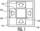
図1は、ディスプレイ110及び典型的なプレースマット120を有する一例としてのディスプレイテーブル100を示す。各プレースマット120は、プライベートビューイング方向122を有し、プレースマット120の下方のディスプレイ110上に表示される情報は、方向122に対向する方向からのビューから見えなくされる。ディスプレイ110はまた、テーブル100における全てのビューアーによる自由なビューイングを可能にする1つ又はそれより多い範囲130を有し得る。
FIG. 1 shows an exemplary display table 100 having a
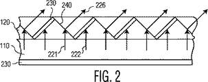
図2は、オーバーレイ120を介してディスプレイ110に対して方向性のある可視性を与える技術の一例を示す。オーバーレイ120は、ディスプレイ110からの光ビーム221,222の伝搬に影響を与える光学素子のシートを有し、例えば特許文献1及び特許文献2中に教示される通りである。オーバーレイ120は、ディスプレイ110から光ビーム222の伝搬を防ぐ光学ブロック要素230と、方向226において光ビーム221を偏向させる表面240とを有する。望ましい方向においてディスプレイから光を放射し、また、ディスプレイ上のオーバーレイシートを介して他の方向において放射するディスプレイからの光を防ぐ他の手段はまた、本発明において使用され得る。
FIG. 2 shows an example of a technique that provides directional visibility to the
本発明によれば、図1中のディスプレイテーブル100は、各プレースマットの位置を検出する位置測定装置(図3中の参照符号310)を有する。かかる位置測定装置は、ディスプレイ110の下方の層230におけるセンサ、又はRF、IR等である他のセンサ、あるいはディスプレイ110の周辺において取り付けられる他のセンサ、ディスプレイ110の表面上に位置決めされるセンサ、又は他の位置測定センサを有し得る。当業者は、ディスプレイ110上のプレースマット120の位置を検出する、これらの及び他の手段を認識する。例えば、プレースマット120は、ディスプレイ110において行及び列の起動信号を検出するオブジェクト125を有し得、また、信号が検出される時間と行及び列の起動信号が適用される時間との間の相互関係は、プレースマット上のセンサの位置を測定するよう使用され得る。あるいは、プレースマット120上のオブジェクト125は、層230又はディスプレイ110の他の位置においてセンサに信号を送るトランスミッタであり得る。例えば、層230は、プレースマット120における電磁コイルからの電流を検出するよう構成されるワイヤのグリッド、又は、プレースマット120における静電板からの電圧を検出するよう構成される表面伝導体のグリッドを有する、従来の離散化タブレットに対応し得る。
According to the present invention, the display table 100 in FIG. 1 has a position measuring device (
顕著である通り、本願中に参照される、1991年7月2日発行、米国特許第5,028,745号明細書、「POSITION DETECTING APPARATUS」は、導体のグリッドを開示する。該導体のグリッドは、共振回路に信号を送り、続いて、グリッドに対する共振回路の位置を測定するよう、共振回路からグリッドに反射される振動を検出する。同様にして、本願中に参照される、2001年5月29日発行、米国特許第6,239,729号明細書、「POSITION DETECTING METHOD AND APPARATUS FOR DETECTING A PLURALITY OF POSITION INDICATORS」は、複数の共振回路を検出する技術を開示する。故に、共振回路をオブジェクト125として実施することによって、プレースマット120の位置は、上述の特許において開示される通り従来の手段を使用して測定され得る。
As is noticeable, US Pat. No. 5,028,745, “POSITION DETECTING APPARATUS”, issued July 2, 1991, referenced herein, discloses a grid of conductors. The grid of conductors sends a signal to the resonant circuit and subsequently detects vibrations reflected from the resonant circuit to the grid to measure the position of the resonant circuit relative to the grid. Similarly, U.S. Pat. No. 6,239,729 issued on May 29, 2001, “POSITION DETECTING METHOD AND APPARATUS FOR DETECTING A PLULARITY OF POSITION INDICATORS” referred to in this application A technique for detecting a circuit is disclosed. Thus, by implementing the resonant circuit as the
同様にして、プレースマット120におけるオブジェクト125は、RFIDトランスミッタであり得る。該RFIDトランスミッタは、ディスプレイテーブル100における位置測定装置によって制御されるトランスミッタからのトリガ信号に応じ、位置測定装置のレシーバにおけるRFIDトランスミッタからの応答の到着及び/又は規模の時間は、オブジェクト125におけるRFIDトランスミッタの位置を測定するよう使用され得る。
Similarly, the
更に他の実施例では、オブジェクト125は、単なる基準マーカーであり、前述の電磁コイル、静電板、RFIDトランスミッタ、又は他の位置識別構成部品は、プレースマット120外部であるスタイラス又はパック等である携帯型機器であり得、プレースマット120上の基準マーカーにおいて置かれる際に位置測定信号を送るよう使用され得る。
In yet another embodiment, the
プレースマット120上のオブジェクト125は、容易に理解されるようにプレースマット120上の固定された位置において1つ又はそれより多い個別の要素として示されるが、当業者は、ディスプレイ110に対するプレースマット120の位置及び向きを測定する役割を果たす方法又は装置が本発明における使用に対して適切である、ことを理解する。例えば、光学系は、ディスプレイ110の上方に位置付けられるカメラ等を使用して、各プレースマット120の位置を測定するよう使用され得る。あるいは、ディスプレイの周辺において対向する光学トランスミッタ−検出器の組は、各プレースマット120の範囲を測定するよう使用され得る。同様に、上述された位置測定スタイラスは、各プレースマット120の輪郭をトレースするよう使用され得る。
Although the
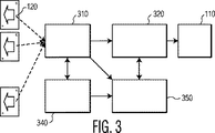
図3は、本発明に従ったディスプレイ装置の典型的なブロック図を示す。ディスプレイ装置は、ディスプレイ110上で各プレースマット120の位置を測定するよう構成されるプレースマット検出器310を有する。意図されるプライバシーを与えるよう、位置の測定は、プレースマット120の向きの測定を有する。
FIG. 3 shows an exemplary block diagram of a display device according to the present invention. The display device has a
望ましい一実施例では、位置識別アイテムは、向き識別特性を有する。例えば、該アイテムがRFIDトランスミッタである場合、プレースマット上の異なる位置における2つのRFIDトランスミッタは、異なる所定の識別子を送るよう構成され得、該識別子は、相対的向きを認識する役割を果たす。即ち、一方の識別子は、プレースマット120の上方左上に置かれるアイテムに対応し得、他方の識別子は、プレースマット120の下方右側に置かれるアイテムに対応し得る。あるいは、向きは、例えばディスプレイ110の最も近い端部に向かって、想定デフォルト値を有し得る。同様に、別個のユーザインタフェースは、各プレースマットの向きを識別するようユーザに対して与えられ得る。プレースマットの向きを測定する他の技術は、本願を考慮する当業者には明らかである。
In a preferred embodiment, the position identification item has an orientation identification characteristic. For example, if the item is an RFID transmitter, two RFID transmitters at different locations on the placemat can be configured to send different predetermined identifiers, which serve to recognize the relative orientation. That is, one identifier may correspond to an item placed on the upper left of the
プレースマット検出器310は、各プレースマット120に対応してディスプレイ110における範囲を作り出すよう、並びに、各プレースマット120の向きに対応する各範囲のビューイング向きを設定するよう構成されるウィンドウコントローラ320に対して、プレースマット120の位置を伝える。
The
ゲームコントローラ等であるアプリケーションコントローラ350は、ウィンドウコントローラ320と相互に作用し、コントローラ320によって作られた異なるウィンドウに対して異なるユーザインタフェース出力ポートを割り当てるようにする。RFIDトランスミッタをプレースマット120上で用いる望ましい一実施例では、一意的な識別信号は、各プレースマット120に対して割り当てられ、プレースマット検出器310は、アプリケーションコントローラ350に対してかかる識別子を伝える。ゲーム環境においては、例えば、プレースマット120は、色分けされたトリムを有し得、コントローラは、対応するウィンドウを赤色のプレーヤ、青色のプレーヤ等に対して割り当てる。その後、赤色のプレーヤに対して向けられたメッセージは、赤色にトリムされたプレースマットに対応するウィンドウに伝えられる。あるいは、ユーザインタフェースは、各プレースマットに対してプレーヤ識別を割り当てるよう、コントローラ350によって与えられ、対応するプレースマットの下方のディスプレイ範囲を介して各プレーヤにメッセージを送る。
An
入力検出器340はまた、ユーザがアプリケーションコントローラ350と相互に作用し得るよう与えられる。また、この同一の検出器340は望ましくは、プレースマット120の位置/向きの測定、プライベートディスプレイ範囲に対する各プレースマット120のマッピング等を促進するよう、上述されたユーザインタフェースに対して使用される。
An
詳述される通り、本発明のディスプレイ装置の各ユーザは、プレースマット120を与えられる。ユーザが自身のプレースマット120をディスプレイ110上へと位置付ける際、プレースマット検出器310は、任意により入力検出器340を介してユーザが与える補助的情報を使用して、プレースマット120の位置及び向きを検出する。プレースマット検出器310は、ウィンドウコントローラ320に各プレースマット120の位置/向きに関する情報を与え、ウィンドウコントローラ320は、各ユーザに対して各プレースマット120の下方の範囲を配置する。アプリケーションコントローラ350は、その後、各ユーザに対して意図された情報をユーザのプレースマット120の下方のディスプレイにおける範囲に方向付ける。プレースマット120がプレースマット120の下方の範囲からの光の方向性ビューイングを与えるため、各ユーザは、ユーザのプレースマット120に対して方向付けられた材料のプライベートビューイングを与えられる。
As detailed, each user of the display device of the present invention is provided with a
前述は単に、本発明の原理を示すものである。故に、当業者は、本願中に明らかに記載又は図示されていないが、本発明の原理を実施し、その趣旨及び範囲内である多種の配置を工夫することができる、ことは十分理解される。例えば、本発明はプライベートな情報を示すよう方向性のある可視性を有するプレースマットを提示するが、本発明の原理は、プレースマットの特徴にかかわらず、また与えられる情報の種類にかかわらず、適用され得る。各プレースマットは、例えばプレースマットの特定のユーザ/オーナーを識別するRFID機器を有し得る。ユーザが自身のプレースマットをディスプレイテーブル上に億歳、装置は、ユーザを認識し、ユーザがディスプレイテーブルに対してどこに位置付けられているかを認識する。その後、ユーザに対して意図される情報は、ユーザの位置においてディスプレイ上に示され得、ディスプレイ装置がインタラクティブである際は、ユーザの位置から到着する入力は、識別されたユーザに対して属される。同様に、各プレースマットがどこに位置決めされるか、並びに、どのように向けられているかを単に知ることによって、装置は、表示される情報をプライベートにしておく必要性の有無にかかわらず、対応する範囲及び適切な向きにおいて情報を表示し得る。これらの及び他の装置構造及び最適化特徴は、本願を考慮する当業者には明らかであり、添付の請求項の範囲内に有される。 The foregoing merely illustrates the principles of the invention. Thus, it will be appreciated that those skilled in the art can practice the principles of the present invention and devise a variety of arrangements that are within its spirit and scope, although not explicitly described or illustrated herein. . For example, while the present invention presents a placemat with directional visibility to show private information, the principles of the present invention are independent of the features of the placemat and regardless of the type of information provided. Can be applied. Each placemat may have an RFID device that identifies the particular user / owner of the placemat, for example. When the user places his placemat on the display table, the device recognizes the user and knows where the user is positioned relative to the display table. Information intended for the user can then be shown on the display at the user's location, and when the display device is interactive, input arriving from the user's location belongs to the identified user. . Similarly, by simply knowing where each placemat is positioned and how it is oriented, the device responds with or without the need to keep the displayed information private. Information can be displayed in range and appropriate orientation. These and other device structures and optimization features will be apparent to those skilled in the art in view of the present application and are within the scope of the appended claims.
かかる請求項の解釈にあたり、以下の点が理解されるべきである:
a) 「有する」という語は、所定の請求項中に列記される要素又は作用以外の要素及び作用の存在を除外するものではない。
b) 単数形で示される要素は、かかる要素の複数の存在を除外するものではない。
c) 請求項中の参照符号は、その範囲を制限するものではない。
d) 複数の「手段」は、同一のアイテム又はハードウェア又はソフトウェアが行う構造又は機能によって示され得る。
e) 開示される要素の各々は、ハードウェア部分(例えば、別個及び一体の電子回路を有する)、ソフトウェア部分(例えば、コンピュータプログラム)、及びそれらの組合せを有し得る。
f) ハードウェア部分は、アナログ部分及びデジタル部分の一方又は両方を有し得る。
g) 開示される機器又はその部分は、特記されない限り、更なる部分と合わせられ得るか、あるいは一体にされ得る。
h) 特定の一連の作用は、特記されない限り、求められるよう意図されない。
i) 複数形で示される要素は、2つ又はそれより多い当該要素を有し、要素の特定の範囲の数を示唆しない。即ち、複数の要素は、わずか2つの要素でもあり得る。
In interpreting such claims, the following points should be understood:
a) The word “comprising” does not exclude the presence of elements and acts other than those listed in a given claim.
b) An element in the singular does not exclude the presence of a plurality of such elements.
c) Reference signs in the claims do not limit their scope.
d) Multiple “means” may be indicated by structures or functions performed by the same item or hardware or software.
e) Each of the disclosed elements may have a hardware portion (eg, having separate and integral electronic circuitry), a software portion (eg, a computer program), and combinations thereof.
f) The hardware part may have one or both of an analog part and a digital part.
g) The disclosed device or part thereof may be combined with further parts or integrated, unless otherwise specified.
h) A specific series of actions is not intended to be required unless otherwise specified.
i) Elements shown in the plural form have two or more such elements and do not imply a particular range of elements. That is, the plurality of elements can be as few as two elements.
Claims (22)
テーブルの天面に対して水平な表示面を有するディスプレイと;
前記ディスプレイの表示面上の位置において置かれ、プライベートビューイング方向を有し、前記位置において前記表示面に表示される情報が前記プライベートビューイング方向に対向する方向からのビューから見えなくされるようにする第1の携帯型プレースマットと;
前記第1のプレースマットとは別個に、前記ディスプレイ、又は前記ディスプレイの周囲若しくは下、又は前記ディスプレイの表示面上に配置され、前記表示面上の前記第1のプレースマットの前記位置を測定するよう構成される、プレースマット検出器と;
前記ディスプレイの表示面を、該表示面上の前記第1のプレースマットの下にあるユーザ範囲を含む複数のディスプレイ範囲へと分割するよう構成される、ウィンドウコントローラと;
前記ウィンドウコントローラと相互に作用して、前記第1のプレースマットに関連付けられるプレーヤに特有の情報を前記ユーザ範囲に表示するよう構成されるアプリケーションコントローラと
を有する装置。The device:
A display having a display surface horizontal to the top of the table ;
It is placed at a position on the display surface of the display , has a private viewing direction, and information displayed on the display surface at the position is made invisible from a view from a direction opposite to the private viewing direction. A first portable placemat to make;
Separately from the first placemat, the display is arranged on or around the display, or on the display surface of the display, and the position of the first placemat on the display surface is measured. Configured with a placemat detector;
The display surface of the display, configured to divide into a plurality of display range including the user range underlying the first place mats on the display surface, and the window controller;
An application controller configured to interact with the window controller to display player specific information associated with the first placemat in the user range .
請求項1記載の装置。The first placemat includes an optical block element that prevents light from propagating from the display surface of the display, and a surface that deflects the light in a specific direction, at the position of the first placemat. Ensure that the information displayed in the corresponding user range is only visible from the private viewing direction,
The apparatus of claim 1.
請求項2記載の装置。The first placemat interacts with the placemat detector to allow the placemat detector to measure the position of the first placemat on the display surface of the display. Having one or more operable objects, the object having a resonant circuit, which generates a vibration in response to a signal transmitted to itself;
The apparatus of claim 2.
請求項1記載の装置。The first placemat interacts with the placemat detector to allow the placemat detector to measure the position of the first placemat on the display surface of the display. Having one or more operable objects, the object having a resonant circuit, which generates a vibration in response to a signal transmitted to itself;
The apparatus of claim 1.
請求項1記載の装置。The first placemat interacts with the placemat detector to allow the placemat detector to measure the position of the first placemat on the display surface of the display. Having one or more operable objects, said object having an RFID transmitter, said RFID transmitter responding to a trigger signal from a transmitter controlled by said placemat detector;
The apparatus of claim 1.
請求項3又は4記載の装置。Before Kipu race mats detector has the display or conductor grid disposed below the display, the grid, the feed signals to the resonant circuit, the from the resonant circuit in response to the signal Detecting the vibration reflected on the grid;
The apparatus according to claim 3 or 4.
請求項5記載の装置。The placemat detector includes the transmitter or the receiver disposed below the display or the display, the transmitter transmits a trigger signal to the RFID transmitter, and the receiver transmits the RFID transmitter to the trigger signal. Receive a response,
The apparatus of claim 5.
前記携帯型機器は、前記ディスプレイの表示面より上方に位置付けられるカメラを有し、前記プレースマット検出器は、前記カメラによって撮影された前記第1のプレースマットの画像に基づき該第1のプレースマットの前記位置を測定する、
請求項1記載の装置。A portable device operably coupled to the placemat detector;
The portable device has a camera positioned above a display surface of the display , and the place mat detector is based on an image of the first place mat photographed by the camera. Measuring the position of
The apparatus of claim 1.
前記携帯型機器は、前記プレースマットの輪郭をトレースするスタイラスを有し、前記プレースマット検出器は、前記スタイラスによるトレースの結果に基づき前記第1のプレースマットの前記位置を測定する、
請求項1記載の装置。A portable device operably coupled to the placemat detector;
The portable device has a stylus that traces the outline of the placemat, and the placemat detector measures the position of the first placemat based on a result of tracing by the stylus.
The apparatus of claim 1.
前記プレースマットの真下の前記表示面の範囲に表示される画像のビューイングを可能にする範囲と、
前記ディスプレイの表示面上の前記プレースマットの前記位置の検出を可能にする1つ又はそれより多い位置決め要素と、
を有し、
前記プレースマットは、プライベートビューイング方向を有し、前記プレースマットの真下の前記表示面の範囲に表示される情報が前記プライベートビューイング方向に対向する方向におけるビューから見えなくされるようにする、
プレースマット。 A portable placemat placed at a position on the display surface of the display that is horizontal to the top of the table :
A range that allows viewing of an image displayed in the range of the display surface directly below the placemat;
And one or more positioning elements to enable the detection of the position of the placemats on the display surface of the display,
Have
The placemat has a private viewing direction so that information displayed in a range of the display surface directly below the placemat is hidden from view in a direction opposite to the private viewing direction;
Place mat.
請求項10記載のプレースマット。The one or more positioning elements have a resonant circuit operable to interact with the display or a grid of conductors provided below the display, the resonant circuit being transmitted from the grid In response to the signal, generating vibrations reflected from the resonant circuit to the grid;
The place mat according to claim 10.
請求項10記載のプレースマット。The one or more positioning elements comprise an RFID device operable to interact with the display or a transmitter and receiver provided below the display, the RFID device being transmitted from the transmitter Providing a response to a trigger signal to the receiver;
The place mat according to claim 10.
請求項10記載のプレースマット。The one or more positioning elements comprise a plurality of elements disposed on the placemat to allow measurement of the orientation of the placemat's rotation relative to the display surface of the display .
The place mat according to claim 10.
前記層は、前記プライベートビューイング方向に対向する方向における前記ディスプレイの表示面からの光の伝播を防ぐ光学ブロック要素と、前記プライベートビューイング方向において前記光を偏向させる面とを有する、
請求項10記載のプレースマット。Further comprising a layer of optical elements that allow the image beneath the placemat to be viewed from the private viewing direction;
The layer includes an optical block element that prevents light from propagating from a display surface of the display in a direction opposite to the private viewing direction, and a surface that deflects the light in the private viewing direction.
The place mat according to claim 10.
請求項14記載のプレースマット。The one or more positioning elements have a resonant circuit operable to interact with the display or a grid of conductors provided below the display, the resonant circuit being transmitted from the grid In response to the signal, generating vibrations reflected from the resonant circuit to the grid;
The placemat according to claim 14.
請求項14記載のプレースマット。The one or more positioning elements comprise an RFID device operable to interact with the display or a transmitter and receiver provided below the display, the RFID device being transmitted from the transmitter Providing a response to a trigger signal to the receiver;
The placemat according to claim 14.
請求項10記載のプレースマット。The one or more positioning elements are arranged on the placemat to allow measurement of the private viewing direction in which the image directly below the placemat is visible;
The place mat according to claim 10.
前記ディスプレイの表示面上での携帯型のプレースマットの位置を測定する段階と、
前記携帯型のプレースマットの前記位置に対応する前記ディスプレイの表示面の範囲において前記画像を表示する段階と、
を有し、
前記プレースマットは、プライベートビューイング方向を有し、前記位置において前記表示面に表示される情報が前記プライベートビューイング方向に対向する方向からのビューから見えなくされるようにする、
方法。A method of displaying an image on the display surface of a display that is horizontal to the top of the table :
Measuring the position of the portable placemat on the display surface of the display ;
Displaying the image in a range of a display surface of the display corresponding to the position of the portable placemat;
Have
The place mat, has a private viewing direction, so that information displayed on the display surface at the position is not visible from the view from a direction opposite to the private viewing direction,
Method.
前記プレースマットの前記向きに基づき前記画像を表示する段階と、
を更に有する、
請求項18記載の方法。And measuring the placemat direction on the display surface of the display,
Displaying the image based on the orientation of the placemat;
Further having
The method of claim 18.
請求項18記載の方法。The placemat includes an optical block element that prevents light from propagating from the display surface of the display, and a surface that deflects the light in a specific direction, and is displayed in a user range corresponding to the position of the placemat. Information to be displayed is only visible from the private viewing direction,
The method of claim 18.
請求項1記載の装置。A further portable placemat placed at a further position on the display surface of the display and having a further private viewing direction different from the private viewing direction of the first placemat; The player associated with the further placemat cannot view the information displayed on the display surface at the further position of the further placemat, and the player associated with the further placemat does not The information displayed on the display surface at the position cannot be seen,
The apparatus of claim 1.
請求項10記載のプレースマット。Two of the positioning elements are placed on opposite sides or corners of the placemat on the horizontal plane,
The place mat according to claim 10.
Applications Claiming Priority (5)
| Application Number | Priority Date | Filing Date | Title |
|---|---|---|---|
| US63066904P | 2004-11-24 | 2004-11-24 | |
| US60/630,669 | 2004-11-24 | ||
| US72460005P | 2005-10-07 | 2005-10-07 | |
| US60/724,600 | 2005-10-07 | ||
| PCT/IB2005/053848 WO2006056939A2 (en) | 2004-11-24 | 2005-11-21 | Privacy overlay for interactive display tables |
Publications (2)
| Publication Number | Publication Date |
|---|---|
| JP2008521048A JP2008521048A (en) | 2008-06-19 |
| JP5154943B2 true JP5154943B2 (en) | 2013-02-27 |
Family
ID=36390291
Family Applications (1)
| Application Number | Title | Priority Date | Filing Date |
|---|---|---|---|
| JP2007542459A Expired - Fee Related JP5154943B2 (en) | 2004-11-24 | 2005-11-21 | Placemat for interactive display table |
Country Status (6)
| Country | Link |
|---|---|
| US (1) | US8487880B2 (en) |
| EP (1) | EP1817088B1 (en) |
| JP (1) | JP5154943B2 (en) |
| KR (1) | KR20070098817A (en) |
| CN (1) | CN101068604B (en) |
| WO (1) | WO2006056939A2 (en) |
Families Citing this family (7)
| Publication number | Priority date | Publication date | Assignee | Title |
|---|---|---|---|---|
| US7734299B2 (en) * | 2007-03-20 | 2010-06-08 | Microsoft Corporation | Facilitating use of a device based on short-range wireless technology |
| US8593255B2 (en) * | 2009-04-24 | 2013-11-26 | Nokia Corporation | Method and apparatus for providing user interaction via transponders |
| EP2270640A1 (en) * | 2009-06-26 | 2011-01-05 | France Telecom | Method for managing display of an application window on a screen, a program and a terminal using same |
| KR20110097083A (en) * | 2010-02-24 | 2011-08-31 | 삼성전자주식회사 | Display device and display system and its external device recognition method |
| US20120032872A1 (en) * | 2010-08-09 | 2012-02-09 | Delphi Technologies, Inc. | Dual view display system |
| US8686958B2 (en) * | 2011-01-04 | 2014-04-01 | Lenovo (Singapore) Pte. Ltd. | Apparatus and method for gesture input in a dynamically zoned environment |
| US10691990B2 (en) | 2016-06-13 | 2020-06-23 | Koninklijke Philips N.V. | System and method for capturing spatial and temporal relationships between physical content items |
Family Cites Families (19)
| Publication number | Priority date | Publication date | Assignee | Title |
|---|---|---|---|---|
| JPS6370326A (en) * | 1986-09-12 | 1988-03-30 | Wacom Co Ltd | Position detector |
| JP3378604B2 (en) * | 1993-03-16 | 2003-02-17 | 株式会社日立製作所 | Information processing device |
| US20030062889A1 (en) * | 1996-12-12 | 2003-04-03 | Synaptics (Uk) Limited | Position detector |
| JP2730018B2 (en) * | 1995-02-28 | 1998-03-25 | 株式会社ワコム | Digitizer and position detection method |
| US5831614A (en) * | 1996-07-01 | 1998-11-03 | Sun Microsystems, Inc. | X-Y viewport scroll using location of display with respect to a point |
| JP3899525B2 (en) * | 1997-11-26 | 2007-03-28 | セイコーエプソン株式会社 | Image processing device |
| WO2000016863A1 (en) | 1998-09-21 | 2000-03-30 | Game Data, Inc. | Gaming apparatus and method |
| JP2000222133A (en) * | 1999-01-28 | 2000-08-11 | Canon Inc | Electronic information display device, display control method thereof, and storage medium |
| JP3703328B2 (en) * | 1999-02-16 | 2005-10-05 | キヤノン株式会社 | Electronic conference system and control method thereof |
| JP2000235352A (en) * | 1999-02-16 | 2000-08-29 | Canon Inc | Display device and game device |
| JP2000235443A (en) | 1999-02-16 | 2000-08-29 | Canon Inc | Electronic conference apparatus, control method therefor, and storage medium |
| US6504649B1 (en) * | 2000-01-13 | 2003-01-07 | Kenneth J. Myers | Privacy screens and stereoscopic effects devices utilizing microprism sheets |
| JP4284855B2 (en) * | 2000-10-25 | 2009-06-24 | ソニー株式会社 | Information input / output system, information input / output method, and program storage medium |
| US6443579B1 (en) * | 2001-05-02 | 2002-09-03 | Kenneth Myers | Field-of-view controlling arrangements |
| US6498590B1 (en) * | 2001-05-24 | 2002-12-24 | Mitsubishi Electric Research Laboratories, Inc. | Multi-user touch surface |
| JP4618401B2 (en) | 2003-07-04 | 2011-01-26 | 富士ゼロックス株式会社 | Information display system and information display method |
| JP4095040B2 (en) * | 2004-02-12 | 2008-06-04 | 株式会社日立製作所 | Display method of table type information terminal |
| US7394459B2 (en) * | 2004-04-29 | 2008-07-01 | Microsoft Corporation | Interaction between objects and a virtual environment display |
| US20060073891A1 (en) * | 2004-10-01 | 2006-04-06 | Holt Timothy M | Display with multiple user privacy |
-
2005
- 2005-11-21 US US11/719,669 patent/US8487880B2/en not_active Expired - Fee Related
- 2005-11-21 CN CN2005800402992A patent/CN101068604B/en not_active Expired - Fee Related
- 2005-11-21 KR KR1020077014294A patent/KR20070098817A/en not_active Withdrawn
- 2005-11-21 JP JP2007542459A patent/JP5154943B2/en not_active Expired - Fee Related
- 2005-11-21 WO PCT/IB2005/053848 patent/WO2006056939A2/en not_active Ceased
- 2005-11-21 EP EP05807142.4A patent/EP1817088B1/en not_active Expired - Lifetime
Also Published As
| Publication number | Publication date |
|---|---|
| US20090174670A1 (en) | 2009-07-09 |
| EP1817088A2 (en) | 2007-08-15 |
| JP2008521048A (en) | 2008-06-19 |
| EP1817088B1 (en) | 2014-06-25 |
| CN101068604A (en) | 2007-11-07 |
| KR20070098817A (en) | 2007-10-05 |
| WO2006056939A2 (en) | 2006-06-01 |
| US8487880B2 (en) | 2013-07-16 |
| CN101068604B (en) | 2011-08-03 |
| WO2006056939A3 (en) | 2006-09-14 |
Similar Documents
| Publication | Publication Date | Title |
|---|---|---|
| JP4294668B2 (en) | Point diagram display device | |
| CN101052444B (en) | Display with multi-user privacy | |
| ES2279823T3 (en) | TACTILE SYSTEM BASED ON CAMERAS. | |
| JP5750229B2 (en) | GAME SYSTEM, GAME SYSTEM CONTROL METHOD, AND GAME SYSTEM DEVICE PROGRAM | |
| US8482557B2 (en) | Device and method for setting instructed position during three-dimensional display, as well as program | |
| US20020175900A1 (en) | Touch input system | |
| TW201015404A (en) | Optical touch display device, optical touch sensing device and touch sensing method | |
| US20130321621A1 (en) | Method for Mapping Hidden Objects Using Sensor Data | |
| JP6827193B2 (en) | Display system, server, display method and equipment | |
| US8899474B2 (en) | Interactive document reader | |
| JPWO2019069575A1 (en) | Information processing equipment, information processing methods and programs | |
| JP5154943B2 (en) | Placemat for interactive display table | |
| US20100245538A1 (en) | Methods and devices for receiving and transmitting an indication of presence | |
| KR20200129131A (en) | Housing structure and input/output device for electronic devices | |
| TW200928879A (en) | Positioning apparatus and related method of orientation devices | |
| CN103154861A (en) | System and method for touch screen | |
| JPH1165814A (en) | Interactive system and image display method | |
| US20210325983A1 (en) | Information providing system and information providing method | |
| JP5782149B2 (en) | Game system and program | |
| JP6078770B2 (en) | GAME DEVICE, GAME DEVICE CONTROL METHOD, AND GAME DEVICE PROGRAM | |
| JP2020088450A (en) | Display device, display system, and control method | |
| ES2318970B1 (en) | INTERACTIVE DEVICE | |
| TWM634499U (en) | Art display monitoring device and system thereof | |
| CN120476339A (en) | Aerial image display device | |
| WO2020240835A1 (en) | Aerial video display device |
Legal Events
| Date | Code | Title | Description |
|---|---|---|---|
| A621 | Written request for application examination |
Free format text: JAPANESE INTERMEDIATE CODE: A621 Effective date: 20081119 |
|
| A131 | Notification of reasons for refusal |
Free format text: JAPANESE INTERMEDIATE CODE: A131 Effective date: 20111025 |
|
| A521 | Request for written amendment filed |
Free format text: JAPANESE INTERMEDIATE CODE: A523 Effective date: 20120113 |
|
| A131 | Notification of reasons for refusal |
Free format text: JAPANESE INTERMEDIATE CODE: A131 Effective date: 20120605 |
|
| A521 | Request for written amendment filed |
Free format text: JAPANESE INTERMEDIATE CODE: A523 Effective date: 20120823 |
|
| TRDD | Decision of grant or rejection written | ||
| A01 | Written decision to grant a patent or to grant a registration (utility model) |
Free format text: JAPANESE INTERMEDIATE CODE: A01 Effective date: 20121113 |
|
| A61 | First payment of annual fees (during grant procedure) |
Free format text: JAPANESE INTERMEDIATE CODE: A61 Effective date: 20121206 |
|
| FPAY | Renewal fee payment (event date is renewal date of database) |
Free format text: PAYMENT UNTIL: 20151214 Year of fee payment: 3 |
|
| R150 | Certificate of patent or registration of utility model |
Ref document number: 5154943 Country of ref document: JP Free format text: JAPANESE INTERMEDIATE CODE: R150 Free format text: JAPANESE INTERMEDIATE CODE: R150 |
|
| R250 | Receipt of annual fees |
Free format text: JAPANESE INTERMEDIATE CODE: R250 |
|
| R250 | Receipt of annual fees |
Free format text: JAPANESE INTERMEDIATE CODE: R250 |
|
| R250 | Receipt of annual fees |
Free format text: JAPANESE INTERMEDIATE CODE: R250 |
|
| R250 | Receipt of annual fees |
Free format text: JAPANESE INTERMEDIATE CODE: R250 |
|
| LAPS | Cancellation because of no payment of annual fees |