JP5151663B2 - Carriage conveyor with lifting function - Google Patents
Carriage conveyor with lifting function Download PDFInfo
- Publication number
- JP5151663B2 JP5151663B2 JP2008122010A JP2008122010A JP5151663B2 JP 5151663 B2 JP5151663 B2 JP 5151663B2 JP 2008122010 A JP2008122010 A JP 2008122010A JP 2008122010 A JP2008122010 A JP 2008122010A JP 5151663 B2 JP5151663 B2 JP 5151663B2
- Authority
- JP
- Japan
- Prior art keywords
- rotating body
- carriage
- cam
- base
- link
- Prior art date
- Legal status (The legal status is an assumption and is not a legal conclusion. Google has not performed a legal analysis and makes no representation as to the accuracy of the status listed.)
- Active
Links
Images
Landscapes
- Automatic Assembly (AREA)
Description
本発明は、被搬送物の高さを作業に適した高さにすることができる、昇降機能を備えた台車コンベアに関するものである。 The present invention relates to a cart conveyor equipped with an elevating function, which can make the height of an object to be conveyed suitable for work.
例えば艤装工場の自動車組立ラインにおいて、内装品等を組み付けるトリム工程や外装品等を組み付けるファイナル工程等において、部品組み付け作業に適した高さに車体を昇降させることができる昇降機能を備えた台車コンベアが使用されており、台車の基台に昇降駆動モータを搭載して被搬送物を載置した搬送台を昇降させるもの、搬送経路に設置した昇降駆動装置により前記搬送台を昇降させるもの、地上に設置したガイドレールにより搬送台を上下方向に直動昇降可能に支持する搬送台昇降支持手段を駆動して前記搬送台を昇降させるもの等がある。
ここで、地上に設置したガイドレールにより搬送台昇降支持手段を駆動する構成のものは、ギヤドモータ等の昇降駆動装置が不要になるとともに、その制御装置も不要になるという特長がある。
For example, in a car assembly line at a garment factory, a cart conveyor equipped with a lifting function that can raise and lower the vehicle body to a height suitable for component assembly work in a trim process for assembling interior parts, etc., or a final process for assembling exterior parts, etc. Is used to raise and lower a transport base on which a transported object is placed by mounting a lift drive motor on the base of the carriage, to lift and lower the transport base by a lift drive device installed in the transport path, There is one that drives a transport table lifting / lowering support means that supports a transport table so that it can be moved up and down in a vertical direction by a guide rail installed on the transport rail.
Here, the structure in which the conveying platform lifting / lowering support means is driven by the guide rail installed on the ground has the feature that the lifting / lowering driving device such as a geared motor is not required and the control device is not required.
このような地上に設置したガイドレールにより搬送台昇降支持手段を駆動する構成の昇降機能を備えた台車コンベアとして、搬送台(被搬送物支持台)を搬送台昇降支持手段であるクロスリンクにより基台(搬送用走行体)に対して昇降可能に支持し、クロスリンクに併設され且つ基台の下側に突出する突出リンクの第一被操作部と、クロスリンクのリンク及び基台側の固定位置間に介装されたトッグルリンクの中間折曲支点又はその近傍に第二被操作部を設け、前記トッグルリンクは、搬送台が下降限高さにあるときに中間折曲支点に対し上側両端支点が走行方向の前後何れか片側にある状態に折り畳まれるとともに、搬送台が中間高さまで上昇したときには、その中間折曲支点に対し上側両端支点が走行方向の前後両側に振り分け状態になるように展開され、この展開状態での前記第二被操作部がこのときの第一被操作部より下方に位置するように構成されており、前記第一被操作部に作用して搬送台を前記中間高さまで上昇させる第一カムレールと、前記第二被操作部に作用して搬送台を前記中間高さから最上高さまで上昇させる第二カムレールとを備えてなるものがある(特許文献1参照。)。 As a cart conveyor equipped with a lifting / lowering function configured to drive the transporting platform lifting / lowering support means by such guide rails installed on the ground, the transporting base (conveyed object support base) is based on a cross link as a transporting platform lifting / lowering supporting means. A first operated part of a projecting link that is supported by a table (transportation traveling body) so as to be movable up and down, and is provided alongside the cross link and projects below the base, and fixing of the cross link and base A second operated portion is provided at or near the intermediate bending fulcrum of the toggle link interposed between the positions, and the toggle link is located at both ends on the upper side with respect to the intermediate bending fulcrum when the carriage is at the lower limit. When the fulcrum is folded to one of the front and rear sides in the running direction, and when the carriage rises to an intermediate height, the upper end fulcrum is divided into the front and rear sides of the running direction. And the second operated part in the expanded state is positioned below the first operated part at this time, and acts on the first operated part to convey the carriage Has a first cam rail that raises the carriage to the intermediate height, and a second cam rail that acts on the second operated portion and raises the transport platform from the intermediate height to the highest height (Patent Document 1). reference.).
特許文献1の昇降機能を備えた台車コンベアによれば、第一被操作部を第一カムレールにより操作して下降限高さから中間高さとし、第二被操作部を第ニカムレールにより操作して中間高さから最上高さとする2段構成により、基台の下側空間の高さを低く保って低床構造にしながら、昇降ストロークを比較的大きくすることができるものである。
しかし、このような構成であっても、クロスリンクに併設する突出リンク並びにクロスリンクのリンク及び基台側の固定位置間に介装されたトッグルリンクのリンク構成上の制約があるため、低床構造を保って昇降ストロークをさらに大きくすることは困難である。
According to the cart conveyor provided with the lifting / lowering function of
However, even in such a configuration, there is a restriction on the link configuration of the protruding link attached to the cross link and the toggle link interposed between the cross link link and the fixed position on the base side. It is difficult to further increase the lifting stroke while maintaining the structure.
そこで本発明が前述の状況に鑑み、解決しようとするところは、低床構造を保ちながら大きな昇降ストロークを容易に確保することができる昇降機能を備えた台車コンベアを提供する点にある。 Therefore, in view of the above-described situation, the present invention intends to provide a cart conveyor having a lifting function capable of easily ensuring a large lifting stroke while maintaining a low floor structure.
本発明に係る昇降機能を備えた台車コンベアは、前記課題解決のために、搬送経路に沿って敷設された軌道上を走行する台車の基台に対して、被搬送物が載置された搬送台を上下方向に直動昇降可能に支持する搬送台昇降支持手段を備え、前記搬送台の高さを低位置から高位置まで可変としてなる昇降機能を備えた台車コンベアであって、前記基台により左右方向の回転軸まわりに回転可能に支持された回転体と、該回転体に、周方向に位相をずらすとともに左右方向に離間させて取り付けられた複数のカムローラと、前記搬送台を昇降させる搬送経路の所定箇所において、前記台車の走行に対応して前記回転体が前進回転又は後進回転するように前記複数のカムローラをそれぞれ従動させる、左右方向に離間させて設置された複数のカムレールと、前記回転体の回転軸と同心に、前記回転体に固定されたプーリと、該プーリに一端が固定され巻回された可撓性長尺部材とを備え、前記回転体の前進回転又は後進回転による前記可撓性長尺部材の巻取り又は繰出しにより前記搬送台昇降支持手段を駆動して前記搬送台を昇降させるものである。 In order to solve the above problems, the cart conveyor having the lifting function according to the present invention is a transport in which an object to be transported is placed on the base of the cart traveling on a track laid along the transport path. A carriage conveyor provided with a carriage raising / lowering support means for supporting a table so that it can be moved up and down in a vertical direction, and having a raising / lowering function capable of changing the height of the carrier from a low position to a high position. , A rotating body supported rotatably around a rotation axis in the left-right direction, a plurality of cam rollers attached to the rotating body with a phase shifted in the circumferential direction and spaced apart in the left-right direction, and the conveyance table raised and lowered A plurality of cam levers spaced apart in the left-right direction are driven so that the plurality of cam rollers are respectively driven so that the rotating body rotates forward or backward in response to traveling of the carriage at a predetermined location on the conveyance path. And a pulley fixed to the rotating body concentrically with the rotating shaft of the rotating body, and a flexible elongate member having one end fixed to the pulley and wound. Alternatively, the transport table lifting / lowering support means is driven to move the transport table up and down by winding or unwinding the flexible long member by reverse rotation.
本発明に係る昇降機能を備えた台車コンベアによれば、搬送経路に沿って敷設された軌道上を走行する台車の基台に対して、被搬送物が載置された搬送台を上下方向に直動昇降可能に支持する搬送台昇降支持手段を備え、前記搬送台の高さを低位置から高位置まで可変としてなる昇降機能を備えた台車コンベアであって、前記基台により左右方向の回転軸まわりに回転可能に支持された回転体と、該回転体に、周方向に位相をずらすとともに左右方向に離間させて取り付けられた複数のカムローラと、前記搬送台を昇降させる搬送経路の所定箇所において、前記台車の走行に対応して前記回転体が前進回転又は後進回転するように前記複数のカムローラをそれぞれ従動させる、左右方向に離間させて設置された複数のカムレールと、前記回転体の回転軸と同心に、前記回転体に固定されたプーリと、該プーリに一端が固定され巻回された可撓性長尺部材とを備え、前記回転体の前進回転又は後進回転による前記可撓性長尺部材の巻取り又は繰出しにより前記搬送台昇降支持手段を駆動して前記搬送台を昇降させるので、基台に支持された回転体に、周方向に位相をずらすとともに左右方向に離間させて複数のカムローラを取り付け、地上に設置したカムレールに前記カムローラを従動させることにより回転体を回転させ、回転体と同心のプーリに巻回された可撓性長尺部材の巻取り又は繰出しにより搬送台昇降支持手段を駆動するため、昇降駆動装置及びその制御装置が不要になる。 According to the cart conveyor equipped with the lifting function according to the present invention, the transport platform on which the object to be transported is placed in the vertical direction with respect to the base of the cart traveling on the track laid along the transport path. A carriage conveyor provided with a carriage raising / lowering support means for supporting a linearly movable raising / lowering and having a raising / lowering function capable of changing the height of the carriage from a low position to a high position, and rotating in the left-right direction by the base A rotating body supported rotatably around an axis, a plurality of cam rollers attached to the rotating body with a phase shifted in the circumferential direction and spaced apart in the left-right direction, and a predetermined portion of a conveying path for moving the conveying table up and down A plurality of cam rails spaced apart in the left-right direction, each driven by the plurality of cam rollers so that the rotating body rotates forward or backward in response to travel of the carriage, and the rotation A pulley fixed to the rotating body concentrically with the rotating shaft, and a flexible long member having one end fixed to and wound around the pulley, and the movable body is configured to rotate the forward or backward rotation of the rotating body. Since the conveying table raising / lowering support means is driven by winding or feeding the flexible long member to raise and lower the conveying table, the phase of the rotating body supported by the base is shifted in the circumferential direction and separated in the left-right direction. A plurality of cam rollers are attached, the cam roller is driven on a cam rail installed on the ground, the rotating body is rotated, and a flexible long member wound around a pulley concentric with the rotating body is wound or fed out. In order to drive the transport table raising / lowering support means, the raising / lowering driving device and its control device are not required.
また、特許文献1のような搬送台昇降支持手段であるクロスリンクに設けた突出リンク及びトッグルリンク等のリンクの被操作部(カム従動ローラー)をカムレールにより操作することにより搬送台昇降支持手段を駆動する構成と比較して、基台に支持された回転体と同心のプーリに巻回された可撓性長尺部材の巻取り又は繰出しにより搬送台昇降支持手段を駆動する構成であるため、搬送台昇降支持手段に操作用のリンクを設ける必要がない。
よって、リンク構成上の制約がないため、低床構造を保ちながら大きな昇降ストロークを容易に確保することができる。
Further, by operating a to-be-operated portion (cam driven roller) of a link such as a projecting link and a toggle link provided on a cross link which is a transport table lifting support means as in
Therefore, since there is no restriction on the link configuration, it is possible to easily ensure a large lifting stroke while maintaining a low floor structure.
次に本発明の実施の形態を添付図面に基づき詳細に説明するが、本発明は、添付図面に示された形態に限定されず特許請求の範囲に記載の要件を満たす実施形態の全てを含むものである。なお、本明細書においては、台車1の搬送方向(図中矢印A参照。)側を前とし、左右は前方に向かっていうものとし、右方から見た図を正面図とする。
また、台車1は、図示しないフリクションローラ式駆動装置、パワーチェーン式駆動装置又は自走式駆動装置等の走行駆動装置により駆動されて搬送経路に沿って搬送されるが、これらの走行駆動装置は一般的な構成であるため、以下においてこれらの詳細説明は省略する。
Next, embodiments of the present invention will be described in detail with reference to the accompanying drawings. However, the present invention is not limited to the embodiments shown in the accompanying drawings, and includes all the embodiments that satisfy the requirements described in the claims. It is a waste. In addition, in this specification, the conveyance direction (refer arrow A in a figure) side of the trolley |
Further, the
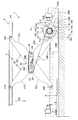
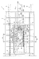
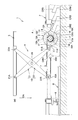
図1〜図3は、本発明の実施の形態に係る昇降機能を備えた台車コンベアの構成を示す概略図であり、図1は搬送台3の高さが高位置Hである場合を示す縦断正面図、図2は同じく平面図、図3は搬送台3の高さが低位置Lである場合を示す縦断正面図である。
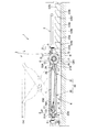
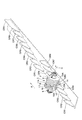
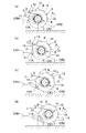
また、図4は回転体5及びカムローラ11,…並びにカムレールCR1,…の例を示す斜視図、図5は回転体5を後進回転させて可撓性長尺部材7をプーリ6から繰り出す場合の例を示す要部拡大正面図、図6は回転体5を前進回転させて可撓性長尺部材7をプーリ6に巻き取る場合の例を示す要部拡大正面図であり、図5及び図6は、上流側である(a)の状態から下流側である(d)の状態まで回転体5が台車1とともに搬送方向Aへ順次移動している状態を示している。
1 to 3 are schematic views showing a configuration of a carriage conveyor having a lifting function according to an embodiment of the present invention, and FIG. 1 is a longitudinal section showing a case where the height of the
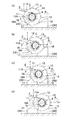
4 is a perspective view showing an example of the rotating
図1〜図3に示すように、本発明の実施の形態に係る昇降機能を備えた台車コンベアは、搬送経路に沿って敷設された左右の走行レールR,R上を転動する前後左右の走行車輪8,…及び左側走行レールRの上部フランジを挟むように、その左右両側面に沿って転動する水平ガイドローラ9,…が取り付けられた台車1の基台2に対して、図示しない被搬送物が載置された搬送台3を上下方向に直動昇降可能に支持する搬送台昇降支持手段4を備え、搬送台3の高さを、例えば低位置L(図3参照。)から高位置H(図1参照。)まで可変とするものである。
As shown in FIG. 1 to FIG. 3, the cart conveyor provided with the lifting function according to the embodiment of the present invention is a front / rear / left / right roll on the left and right traveling rails R, R laid along the transport path. The
そして、搬送台昇降支持手段4の例えば前側に位置し、基台2により左右方向の回転軸Cまわりに回転可能に支持された回転体5と、回転体5に、周方向に位相をずらすとともに左右方向に離間させて取り付けられた複数のカムローラ11,12,…と、搬送台3を昇降させる搬送経路の所定箇所において、台車1の走行に対応して回転体5が前進回転又は後進回転するように複数のカムローラ11,12,…をそれぞれ従動させる、左右方向に離間させて設置された複数のカムレールCR1,CR2,…と、回転体5の回転軸Cと同心に、回転体5の左右両側に固定されたプーリ6,6と、プーリ6,6に一端が固定され巻回された可撓性長尺部材であるベルト7,7とを備えている。
The phase is shifted in the circumferential direction between the
次に、搬送台昇降支持手段4の構成例について説明する。
搬送台3の左右に位置してX字状対称リンク(クロスリンク)10,10を構成するリンク21及び22は同じ長さであり、リンク22の上端部は左右方向軸22Aまわりに回動可能に搬送台3と連結され、左右方向軸22A直下のリンク21の下端部は、左右方向軸21Bまわりに回動可能に基台2と回動可能に連結される。
また、リンク21の上端部は、左右方向軸21Aまわりに回動可能に搬送台3と連結されるとともに左右方向軸21Aが前後方向にスライド可能に支持され、左右方向軸21A直下のリンク22の下端部は、左右方向軸22Bまわりに回動可能に基台3と連結されるとともに左右方向軸22Bが前後方向にスライド可能に支持される。
Next, the structural example of the conveyance stand raising / lowering support means 4 is demonstrated.
The
Further, the upper end portion of the
さらに、リンク21及び22の上下の支軸21A,21B及び22A,22B間の中点は支軸20により連結されるため、リンク21及び22は、支軸20まわりに相対的に回動可能に構成された前記X字状対称リンク10となっている。
該X字状対称リンク10は、上端部(左右方向軸21A,22A)間の距離又は下端部(左右方向軸22B,21B)間の距離を変化させると上下に伸縮し、搬送台3は基台2に対して上下方向に直動昇降する。
なお、搬送台昇降支持手段4は、X字状対称リンク10,10に限定されるものではなく、X字状対称リンク10を複数組み合わせたものを用いることもできるし、複数の平行リンク機構を組み合わせた構成等を用いてもよい。
Furthermore, since the midpoints between the upper and
The X-shaped
In addition, the conveyance stand raising / lowering support means 4 is not limited to the X-shaped
左右のX字状対称リンク10,10の交差部の後側に位置する支軸25には、その左右にプーリ27,27が取り付けられ、プーリ27,27の左右方向外側に同心に取り付けられたローラ23,…が、リンク21の上側後面21Cとリンク22の下側後面22Dに当接する。
また、左右のX字状対称リンク10,10の交差部の前側に位置する支軸26には、その左右にプーリ28,28が取り付けられ、プーリ28,28の左右方向外側に同心に取り付けられたローラ24,…が、リンク22の上側前面22Cとリンク21の下側前面21Dに当接する。
そして、回転体5の左右両側のプーリ6,6に巻回されたベルト7,7が、X字状対称リンク10,10の交差部後側のプーリ27,27及び前記交差部前側のプーリ28,28に掛け渡された後、支軸25に取り付けられたブラケット29Aに掛止部材29Bにより掛止される。
Pulleys 27, 27 are attached to the left and right sides of the
In addition,
The
次に、回転体5及び複数のカムローラ11,12,…の構成例について説明する。
図1〜図4に示すように、回転軸Cまわりに回転可能に基台2により支持された回転体5は、回転軸Cまわりの周方向に45°ピッチで位相をずらすとともに左右方向に離間する8個のカムローラ11,12,…,18が、それぞれ支軸11A,12A,…,18Aまわりに回転可能に取り付けられており、これらカムローラ11,12,…,18が、搬送経路の所定箇所に設置されたカムレールCR1,CR2,…,CR8により従動するため、回転体5は前進回転又は後進回転する。
Next, a configuration example of the
As shown in FIGS. 1 to 4, the
次に、搬送台3の高さを保持した状態で作業を行う構成例について説明する。
図1及び図2に示すように、水平上面を有して前後方向に延びる高さ保持用カムレールCRH上をカムローラ11が転動しながら台車1が走行している状態では、回転体5が回転しないことから、搬送台3の高さ(高位置H)が保持されるため、この状態で搬送台3上の被搬送物への部品組み付け作業等を行うことができる。
なお、カムローラ11,12,…18の1個を高さ保持用カムレールCRH上を転動させる構成により、搬送台3の高さを高位置Hと低位置Lの中間の任意の高さに保持することができる。
Next, a configuration example in which work is performed while the height of the transfer table 3 is maintained will be described.
As shown in FIGS. 1 and 2, the
It should be noted that one of the
次に、図1、図2及び図5を参照して、高位置Hにある搬送台3を下降させる動作について説明する。
搬送台3を下降させる箇所には、前下がり傾斜面を有する下降用カムレールCR1,CR2,…が設置されており、台車1の走行に伴い、前記カムレールの前下がり傾斜面に沿ってカムローラ11,12,…が転動する際に、回転体5は後進回転する(図5中の矢印B参照。)。
例えば、図5(a)の状態から図5(b)、図5(c)の状態まで台車1とともに回転体5が前進すると、カムローラ11がカムレールCR1の前下がり傾斜面に沿って転動し、このようにカムレールCR1に従動するカムローラ11により回転体5は後進回転する(図5中の矢印B参照。)。
Next, with reference to FIG. 1, FIG. 2, and FIG. 5, the operation of lowering the transport table 3 at the high position H will be described.
Lowering cam rails
For example, when the
そして、カムローラ11がカムレールCR1の前下がり傾斜面から離れる前に、図5(d)に示すように、カムローラ12がカムレールCR2の前下がり傾斜面に沿って転動し、カムレールCR2に従動するカムローラ12により回転体5は後進回転する(図5(d)中の矢印B参照。)。
同様に、順次、カムローラCR3に従動するカムローラ13、カムローラCR4に従動するカムローラ14,…と引き継がれながら回転体5は後進回転する。
Then, as shown in FIG. 5 (d), the
Similarly, the
したがって、ベルト7,7が繰り出され(図5中の矢印D参照。)、被搬送物及び搬送台3等の自重により、ローラ23,…がリンク21の上側後面21C及びリンク22の下側後面22Dに当接しながらX字状対称リンク10に対して相対的に後方へ移動するとともに、ローラ24,…がリンク22の上側前面22C及びリンク21の下側前面21Dに当接しながらX字状対称リンク10に対して相対的に前方へ移動し、被搬送物及び搬送台3が下降するため(図1中の矢印DN参照。)、図3に示す低位置Lとすることができる。
Therefore, the
次に、図3、図4及び図6を参照して、低位置Lにある搬送台3を上昇させる動作について説明する。
搬送台3を上昇させる箇所には、前上がり傾斜面を有する上昇用カムレールCR1,CR2,…が設置されており、台車1の走行に伴い、前記カムレールの前上がり傾斜面に沿ってカムローラ11,12,…が転動する際に、回転体5は前進回転する(図6中の矢印F参照。)。
例えば、図6(a)の状態から図6(b)、図6(c)の状態まで台車1とともに回転体5が前進すると、カムローラ18がカムレールCR1の前上がり傾斜面に沿って転動し、このようにカムレールCR1に従動するカムローラ18により回転体5は前進回転する(図6中の矢印F参照。)。
Next, with reference to FIGS. 3, 4, and 6, an operation for raising the transport table 3 at the low position L will be described.
Ascending cam rails CR1, CR2,... Having a front rising inclined surface are installed at locations where the conveying table 3 is raised, and as the
For example, when the
そして、カムローラ18がカムレールCR1の前上がり傾斜面から離れる前に、図6(d)に示すように、カムローラ17がカムレールCR2の前上がり傾斜面に沿って転動し、カムレールCR2に従動するカムローラ17により回転体5は前進回転する(図6(d)中の矢印F参照。)。
同様に、順次、カムローラCR3に従動するカムローラ16、カムローラCR4に従動するカムローラ15,…と引き継がれながら回転体5は前進回転する。
Then, before the
Similarly, the
したがって、ベルト7,7が巻き取られ(図6中の矢印E参照。)、該ベルト7,7の張力により、ローラ23,…がリンク21の上側後面21C及びリンク22の下側後面22Dに当接しながらX字状対称リンク10に対して相対的に前方へ移動するとともに、ローラ24,…がリンク22の上側前面22C及びリンク21の下側前面21Dに当接しながらX字状対称リンク10に対して相対的に後方へ移動し、被搬送物及び搬送台3が上昇するため(図3中の矢印UP参照。)、図3の二点鎖線及び図1に示す高位置Hとすることができる。
Therefore, the
なお、例えば図1に示すように、ローラ23,…が転動するリンク21の上側後面21C及びリンク22の下側後面22D並びにローラ24,…が転動するリンク22の上側前面22C及びリンク21の下側前面21Dの形状を左右方向から見て曲線形状としており、この曲線形状は、搬送台3の昇降速度が等速になるように決定される。
For example, as shown in FIG. 1, the upper rear surface 21C of the
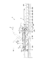
次に、昇降機能を備えた台車コンベアの別構成例について説明する。
図7は搬送台3の高さが高位置Hである場合を示す縦断正面図、図8は搬送台3の高さが低位置Lである場合を示す縦断正面図であり、図1〜図3の台車コンベアとは、ベルト7,7の巻取り又は繰出しにより搬送台昇降支持手段4を駆動する構成のみが異なっている。
すなわち、左右のX字状対称リンク10,10の下側後部の前後方向にスライド可能に支持された左右方向軸22B,22Bにプーリ19A,19Aを取り付けており、回転体5の左右両側のプーリ6,6に巻回されたベルト7,7が、プーリ19A,19Aに掛け渡された後、基台2に掛止部材19Bにより掛止される。
Next, another configuration example of the cart conveyor having the lifting function will be described.
FIG. 7 is a longitudinal front view showing the case where the height of the transfer table 3 is at the high position H, and FIG. 8 is a vertical front view showing the case where the height of the transfer table 3 is at the low position L. 3 differs only in the structure which drives the conveyance stand raising / lowering support means 4 by winding or feeding out the
That is, the
このような構成によっても、ベルト7,7の巻取り又は繰出しにより搬送台昇降支持手段4を駆動することができ、図7に示す前下がり傾斜面を有する下降用カムレールCR1,CR2,…にカムローラ11,12,…を従動させて回転体5を後進回転させることにより、ベルト7,7が繰り出されるため、被搬送物及び搬送台3を自重により下降させて(図7中の矢印DN参照。)、前述と同様に図8に示す低位置Lとすることができる。
また、図8に示す前上がり傾斜面を有する上昇用カムレールCR1,CR2,…にカムローラ18,17,…を従動させて回転体5を前進回転させることにより、ベルト7,7が巻き取られるため、被搬送物及び搬送台3をベルト7,7の張力により上昇させて(図8中の矢印UP参照。)、前述と同様に図7に示す高位置Hとすることができる。
Even with such a configuration, it is possible to drive the transporting platform lifting / lowering support means 4 by winding or unwinding the
Further, the
以上のような構成によれば、基台2に支持された回転体5に、周方向に位相をずらすとともに左右方向に離間させて複数のカムローラ11,12,…を取り付け、地上に設置したカムレールCR1,CR2,…にカムローラ11,12,…を従動させることにより回転体5を回転させ、回転体5と同心のプーリ6,6に巻回されたベルト7,7の巻取り又は繰出しにより搬送台昇降支持手段4を駆動するため、昇降駆動装置及びその制御装置が不要になる。
また、基台2に支持された回転体5と同心のプーリ6,6に巻回されたベルト7,7の巻取り又は繰出しにより搬送台昇降支持手段4を駆動する構成であることから、搬送台昇降支持手段4に操作用のリンクを設ける必要がなく、リンク構成上の制約がないため、低床構造を保ちながら大きな昇降ストロークを容易に確保することができる。
According to the above configuration, a plurality of
Further, since the conveyor base lifting / lowering support means 4 is driven by winding or feeding of the
以上の説明においては、可撓性長尺部材がベルト7,7である場合について説明したが、ベルトに限定されるものではなく、被搬送物の重量等の仕様によっては、可撓性長尺部材として例えばワイヤー等を用いてもよい。
In the above description, the case where the flexible long member is the
A 搬送方向
B 後進回転方向
C 回転軸
CR1,CR2,CR3,CR4,CR5,CR6,CR7,CR8 カムレール
D 繰出し方向
DN 下降方向
E 巻取り方向
F 前進回転方向
H 高位置
L 低位置
UP 上昇方向
1 台車
2 基台
3 搬送台
4 搬送台昇降支持手段
5 回転体
6 プーリ
7 ベルト(可撓性長尺部材)
11,12,13,14,15,16,17,18 カムローラ
A Transport direction B Reverse rotation direction C Rotating shaft CR1, CR2, CR3, CR4, CR5, CR6, CR7, CR8 Cam rail D Feeding direction DN Lowering direction E Winding direction F Forward rotation direction H High position L Low position UP Up
11, 12, 13, 14, 15, 16, 17, 18 Cam roller
Claims (1)
前記基台により左右方向の回転軸まわりに回転可能に支持された回転体と、
該回転体に、周方向に位相をずらすとともに左右方向に離間させて取り付けられた複数のカムローラと、
前記搬送台を昇降させる搬送経路の所定箇所において、前記台車の走行に対応して前記回転体が前進回転又は後進回転するように前記複数のカムローラをそれぞれ従動させる、左右方向に離間させて設置された複数のカムレールと、
前記回転体の回転軸と同心に、前記回転体に固定されたプーリと、
該プーリに一端が固定され巻回された可撓性長尺部材とを備え、
前記回転体の前進回転又は後進回転による前記可撓性長尺部材の巻取り又は繰出しにより前記搬送台昇降支持手段を駆動して前記搬送台を昇降させることを特徴とする昇降機能を備えた台車コンベア。
With respect to the base of the carriage that runs on the track laid along the transport path, the transport base lifting support means for supporting the transport base on which the object to be transported is vertically movable up and down is provided. A carriage conveyor having a lifting function that makes the height of the transfer table variable from a low position to a high position,
A rotating body supported by the base so as to be rotatable around a rotation axis in the left-right direction;
A plurality of cam rollers attached to the rotating body with a phase shifted in the circumferential direction and spaced apart in the left-right direction;
At predetermined locations on the conveyance path for raising and lowering the conveyance table, the plurality of cam rollers are respectively driven so that the rotating body rotates forward or backward in accordance with the traveling of the carriage, and is installed separately in the left-right direction. A plurality of cam rails,
A pulley fixed to the rotating body concentrically with the rotating shaft of the rotating body;
A flexible elongated member having one end fixed and wound around the pulley;
A carriage equipped with an elevating function, wherein the conveying table raising / lowering support means is driven to raise and lower the conveying table by winding or unwinding the flexible long member by forward rotation or backward rotation of the rotating body. Conveyor.
Priority Applications (1)
| Application Number | Priority Date | Filing Date | Title |
|---|---|---|---|
| JP2008122010A JP5151663B2 (en) | 2008-05-08 | 2008-05-08 | Carriage conveyor with lifting function |
Applications Claiming Priority (1)
| Application Number | Priority Date | Filing Date | Title |
|---|---|---|---|
| JP2008122010A JP5151663B2 (en) | 2008-05-08 | 2008-05-08 | Carriage conveyor with lifting function |
Publications (2)
| Publication Number | Publication Date |
|---|---|
| JP2009269716A JP2009269716A (en) | 2009-11-19 |
| JP5151663B2 true JP5151663B2 (en) | 2013-02-27 |
Family
ID=41436634
Family Applications (1)
| Application Number | Title | Priority Date | Filing Date |
|---|---|---|---|
| JP2008122010A Active JP5151663B2 (en) | 2008-05-08 | 2008-05-08 | Carriage conveyor with lifting function |
Country Status (1)
| Country | Link |
|---|---|
| JP (1) | JP5151663B2 (en) |
Families Citing this family (5)
| Publication number | Priority date | Publication date | Assignee | Title |
|---|---|---|---|---|
| US8641809B2 (en) | 2010-10-26 | 2014-02-04 | Munters Corporation | Rotor support system |
| CN105438814B (en) * | 2016-01-04 | 2017-11-03 | 广东溢达纺织有限公司 | Automatic feeding |
| JP6728967B2 (en) * | 2016-05-19 | 2020-07-22 | 中西金属工業株式会社 | Cart conveyor with lifting function |
| CN110894002B (en) * | 2018-09-13 | 2024-06-25 | 上海旭恒精工机械制造有限公司 | Full-automatic typesetting conveying device |
| CN109095150B (en) * | 2018-10-29 | 2024-05-14 | 湖南精正设备制造有限公司 | Station conveyer that transmission precision is high of long distance transportation |
Family Cites Families (8)
| Publication number | Priority date | Publication date | Assignee | Title |
|---|---|---|---|---|
| JPH02103015U (en) * | 1989-02-03 | 1990-08-16 | ||
| JPH06135694A (en) * | 1993-02-18 | 1994-05-17 | Towa Kogyo Kk | Elevator device and working bench |
| JP2959341B2 (en) * | 1993-06-07 | 1999-10-06 | 株式会社ダイフク | Lifter |
| JPH07233865A (en) * | 1994-02-18 | 1995-09-05 | Mitsuhashi Seisakusho:Kk | Cam device |
| JPH08217391A (en) * | 1995-02-10 | 1996-08-27 | Meikikou:Kk | Table lift equipment |
| JP2001019373A (en) * | 1999-07-12 | 2001-01-23 | Ace Setsubi:Kk | Motor-driven lift |
| JP4196348B2 (en) * | 2004-08-09 | 2008-12-17 | 株式会社ダイフク | Transport device |
| JP4433941B2 (en) * | 2004-08-26 | 2010-03-17 | 株式会社ダイフク | Transport device |
-
2008
- 2008-05-08 JP JP2008122010A patent/JP5151663B2/en active Active
Also Published As
| Publication number | Publication date |
|---|---|
| JP2009269716A (en) | 2009-11-19 |
Similar Documents
| Publication | Publication Date | Title |
|---|---|---|
| CN102639380B (en) | Item conveyance infrastructure | |
| JP5206020B2 (en) | Transport device | |
| JP5212836B2 (en) | Work transfer equipment | |
| JP5151663B2 (en) | Carriage conveyor with lifting function | |
| CN103998359B (en) | Handling device | |
| JP6350166B2 (en) | Goods transport cart | |
| JP2012035945A (en) | Conveyance apparatus using traveling body for conveyance | |
| JP2009083952A (en) | Overhead conveyor with lifting function on carrier | |
| JP2018122985A (en) | Rail for classifying conveyor | |
| US9010525B2 (en) | Slat conveyor apparatus | |
| JP5621985B2 (en) | Slat conveyor | |
| JP4120626B2 (en) | Transport device | |
| JP5999934B2 (en) | Fixed circulation gondola lift stop structure | |
| JP6728967B2 (en) | Cart conveyor with lifting function | |
| JP6218044B2 (en) | Carriage transfer device | |
| JP5983448B2 (en) | Work transfer device | |
| JP4450200B2 (en) | Transport cart with lifting function | |
| JP2008239292A (en) | Transfer equipment | |
| CN101142131B (en) | Roller conveyor | |
| JP4805684B2 (en) | Cross belt sorter | |
| JP3905532B2 (en) | Car body transport mechanism | |
| JP2017165508A (en) | Cart carrier | |
| JP5561005B2 (en) | Conveying device using a traveling body for transportation | |
| JP5831721B2 (en) | Slat conveyor | |
| JP5393788B2 (en) | Vehicle with work table |
Legal Events
| Date | Code | Title | Description |
|---|---|---|---|
| A621 | Written request for application examination |
Free format text: JAPANESE INTERMEDIATE CODE: A621 Effective date: 20110223 |
|
| A977 | Report on retrieval |
Free format text: JAPANESE INTERMEDIATE CODE: A971007 Effective date: 20120702 |
|
| TRDD | Decision of grant or rejection written | ||
| A01 | Written decision to grant a patent or to grant a registration (utility model) |
Free format text: JAPANESE INTERMEDIATE CODE: A01 Effective date: 20121106 |
|
| A61 | First payment of annual fees (during grant procedure) |
Free format text: JAPANESE INTERMEDIATE CODE: A61 Effective date: 20121119 |
|
| FPAY | Renewal fee payment (event date is renewal date of database) |
Free format text: PAYMENT UNTIL: 20151214 Year of fee payment: 3 |
|
| R150 | Certificate of patent or registration of utility model |
Ref document number: 5151663 Country of ref document: JP Free format text: JAPANESE INTERMEDIATE CODE: R150 Free format text: JAPANESE INTERMEDIATE CODE: R150 |
|
| R250 | Receipt of annual fees |
Free format text: JAPANESE INTERMEDIATE CODE: R250 |
|
| R250 | Receipt of annual fees |
Free format text: JAPANESE INTERMEDIATE CODE: R250 |
|
| R250 | Receipt of annual fees |
Free format text: JAPANESE INTERMEDIATE CODE: R250 |
|
| R250 | Receipt of annual fees |
Free format text: JAPANESE INTERMEDIATE CODE: R250 |
|
| R250 | Receipt of annual fees |
Free format text: JAPANESE INTERMEDIATE CODE: R250 |
|
| R250 | Receipt of annual fees |
Free format text: JAPANESE INTERMEDIATE CODE: R250 |
|
| R250 | Receipt of annual fees |
Free format text: JAPANESE INTERMEDIATE CODE: R250 |
|
| R250 | Receipt of annual fees |
Free format text: JAPANESE INTERMEDIATE CODE: R250 |
|
| R250 | Receipt of annual fees |
Free format text: JAPANESE INTERMEDIATE CODE: R250 |
|
| R250 | Receipt of annual fees |
Free format text: JAPANESE INTERMEDIATE CODE: R250 |
|
| R250 | Receipt of annual fees |
Free format text: JAPANESE INTERMEDIATE CODE: R250 |