JP5149906B2 - Fluid dosing device - Google Patents
Fluid dosing device Download PDFInfo
- Publication number
- JP5149906B2 JP5149906B2 JP2009532858A JP2009532858A JP5149906B2 JP 5149906 B2 JP5149906 B2 JP 5149906B2 JP 2009532858 A JP2009532858 A JP 2009532858A JP 2009532858 A JP2009532858 A JP 2009532858A JP 5149906 B2 JP5149906 B2 JP 5149906B2
- Authority
- JP
- Japan
- Prior art keywords
- block
- drive head
- administration device
- fluid
- hole
- Prior art date
- Legal status (The legal status is an assumption and is not a legal conclusion. Google has not performed a legal analysis and makes no representation as to the accuracy of the status listed.)
- Expired - Fee Related
Links
Images


Classifications
-
- B—PERFORMING OPERATIONS; TRANSPORTING
- B65—CONVEYING; PACKING; STORING; HANDLING THIN OR FILAMENTARY MATERIAL
- B65D—CONTAINERS FOR STORAGE OR TRANSPORT OF ARTICLES OR MATERIALS, e.g. BAGS, BARRELS, BOTTLES, BOXES, CANS, CARTONS, CRATES, DRUMS, JARS, TANKS, HOPPERS, FORWARDING CONTAINERS; ACCESSORIES, CLOSURES, OR FITTINGS THEREFOR; PACKAGING ELEMENTS; PACKAGES
- B65D55/00—Accessories for container closures not otherwise provided for
- B65D55/02—Locking devices; Means for discouraging or indicating unauthorised opening or removal of closure
- B65D55/10—Locking pins
-
- B—PERFORMING OPERATIONS; TRANSPORTING
- B05—SPRAYING OR ATOMISING IN GENERAL; APPLYING FLUENT MATERIALS TO SURFACES, IN GENERAL
- B05B—SPRAYING APPARATUS; ATOMISING APPARATUS; NOZZLES
- B05B11/00—Single-unit hand-held apparatus in which flow of contents is produced by the muscular force of the operator at the moment of use
- B05B11/01—Single-unit hand-held apparatus in which flow of contents is produced by the muscular force of the operator at the moment of use characterised by the means producing the flow
- B05B11/10—Pump arrangements for transferring the contents from the container to a pump chamber by a sucking effect and forcing the contents out through the dispensing nozzle
- B05B11/1042—Components or details
- B05B11/1059—Means for locking a pump or its actuation means in a fixed position
-
- B—PERFORMING OPERATIONS; TRANSPORTING
- B65—CONVEYING; PACKING; STORING; HANDLING THIN OR FILAMENTARY MATERIAL
- B65D—CONTAINERS FOR STORAGE OR TRANSPORT OF ARTICLES OR MATERIALS, e.g. BAGS, BARRELS, BOTTLES, BOXES, CANS, CARTONS, CRATES, DRUMS, JARS, TANKS, HOPPERS, FORWARDING CONTAINERS; ACCESSORIES, CLOSURES, OR FITTINGS THEREFOR; PACKAGING ELEMENTS; PACKAGES
- B65D83/00—Containers or packages with special means for dispensing contents
- B65D83/14—Containers or packages with special means for dispensing contents for delivery of liquid or semi-liquid contents by internal gaseous pressure, i.e. aerosol containers comprising propellant for a product delivered by a propellant
- B65D83/75—Aerosol containers not provided for in groups B65D83/16 - B65D83/74
- B65D83/757—Tamper-indicating means
- B65D83/7575—Separate tamper-elements
Landscapes
- Chemical & Material Sciences (AREA)
- Dispersion Chemistry (AREA)
- Engineering & Computer Science (AREA)
- Mechanical Engineering (AREA)
- Containers And Packaging Bodies Having A Special Means To Remove Contents (AREA)
- Closures For Containers (AREA)
- Devices For Dispensing Beverages (AREA)
- External Artificial Organs (AREA)
- Centrifugal Separators (AREA)
- Coating Apparatus (AREA)
- Loading And Unloading Of Fuel Tanks Or Ships (AREA)
- Infusion, Injection, And Reservoir Apparatuses (AREA)
Abstract
Description
本発明は、流体投与装置、さらに具体的に言えば、当該装置が使用と使用の合間に駆動するのを防ぐことが可能なブロック部品を有する、という装置に関する。 The present invention relates to a fluid dispensing device, and more particularly to a device having a block component that can prevent the device from being driven between uses.
流体投与装置が駆動と駆動の合間に駆動されるのを防ぐために用いられるシステムは公知で、そうしたシステムは一般的に、クリップといった取り外し可能な装置を有し、当該取り外し可能な装置は、駆動ヘッドまたはプッシャの下にこれらの移動を防ぐ形で装着されている。そうした取り外し可能な装置の問題点は、たとえば鞄の中で持ち運ばれる際にひとりでに外れてしまう点である。装置に一体化され、取り外しができないシステムも存在するが、そうしたシステムは、一般的に製造および組み立てが極めて複雑で、投与装置の部品のいくつかについて形を変える必要があり、そのため、コストが大きく上昇する。特許文書US6 186 365号およびLU84 436号には、既存の装置について説明がある。 Systems used to prevent fluid dispensing devices from being driven between drives are known and such systems generally have a removable device, such as a clip, that is removable from the drive head. Or, it is mounted under the pusher in a form that prevents these movements. The problem with such removable devices is that they can come off by themselves, for example when carried in a bag. Some systems are integrated into the device and cannot be removed, but such systems are generally very complex to manufacture and assemble and require changes to some of the parts of the dosing device, which can be costly To rise. Patent documents US Pat. No. 6,186,365 and LU 84 436 describe existing devices.
本発明は、上記の問題を生じない流体投与装置を提供することを目的とする。
さらに具体的に言えば、本発明は、製造および組み立てが簡単かつ低コストな駆動ブロック部品を有する流体投与装置を提供することを目的とする。
また、本発明は、投与装置の構成部品に大きな変形を加える必要なく、既存の装置に容易に適合させることができるという流体投与装置を提供することを目的とする。
An object of this invention is to provide the fluid administration apparatus which does not produce said problem.
More specifically, it is an object of the present invention to provide a fluid dispensing device having a drive block component that is simple and inexpensive to manufacture and assemble.
It is another object of the present invention to provide a fluid administration device that can be easily adapted to an existing device without requiring significant deformation of the components of the administration device.
また、本発明は、装置がすでに使用済みかどうか簡単に見て取ることができる装置を提供することを目的とする。
また、本発明は、安全かつ信頼性のある形で動作し、ユーザが簡単に駆動できる装置を提供することを目的とする。
It is another object of the present invention to provide an apparatus that can be easily seen whether the apparatus has already been used.
Another object of the present invention is to provide a device that operates in a safe and reliable manner and can be easily driven by a user.
このため、本発明は、流体投与装置であって、手動で駆動されるポンプまたは弁という流体投与部材であって、固定リングにより容器に固定される、という前記流体投与部材と、前記流体投与部材に配置され、移動することで前記流体投与部材を駆動することが可能な駆動ヘッドと、ブロック位置において、流体投与部材が駆動しないようにする取り外し可能なブロック部品と、を有し、前記ブロック部品は、少なくとも1つのブロック用突起部分を有して、駆動ヘッドに組み付けられており、当該ブロック用突起部分が、前記駆動ヘッドに設けられた少なくとも1つの穴を通ることにより、固定リングまたは当該固定リングに固着された部品と協働することを特徴とする。 For this reason, the present invention is a fluid dispensing device, which is a fluid dispensing member such as a manually driven pump or valve, which is fixed to a container by a fixing ring, and the fluid dispensing member disposed has a drive head capable of driving said fluid dispensing member by moving, in block position, a removable block component fluid dispenser member is prevented from driving, and, before Symbol block parts, has at least one block protrusion portion, is assembled to the drive head, the block projections portions, by passing Rukoto at least one hole provided in the drive head, the fixing ring or It is characterized by cooperating with a part fixed to the fixing ring .
効果的な構成として、前記ブロック部品は、流体投与部材の縦軸を横断する方向に、並進の形で移動が可能である。
効果的な構成として、前記ブロック部品は折ることのできる部品を少なくとも1つ有し、当該折ることのできる部品は、前記ブロック部品が初めてブロック位置から取り外される際に壊れるよう作られている。
As an advantageous configuration, the block part is movable in a translational manner in a direction transverse to the longitudinal axis of the fluid delivery member.
As effective configuration, the block parts at least one has a component that can be folded parts that can be folded such is made to break when the blocking part is removed from the first blocking position.
効果的な構成として、前記少なくとも1つの折ることのできる部品はタブで形成され、当該タブは、前記少なくとも1つの穴の少なくとも1つのエッジと協働する。
効果的な構成として、前記ヘッドは少なくとも2つの穴を有し、そのうち少なくとも1つの穴にはブロック用突起部分が、そのうち少なくとも1つの穴には折ることのできる部品が収容される。
In an advantageous configuration, the at least one foldable part is formed by a tab, the tab cooperating with at least one edge of the at least one hole.
As an effective configuration, the head has at least two holes, in which at least one hole accommodates a block protrusion and at least one hole accommodates a foldable part.
ブロック部品は、ブロック位置において、少なくとも部分的に前記ヘッドを囲む形で延びている。
効果的な構成として、ブロック部品は開リングを有し、当該開リングは2つのブロック用突起部分を有し、それら部分のそれぞれの端部エッジには折ることのできる部品が設けられ、前記ヘッドは4つの穴を有し、そのうち2つには、ブロック位置において、前記ブロック用突起部分が、そのうち2つには、ブロック位置かつ初回の使用の前の段階で、前記折ることのできる部品が収容される。
The block part extends at least partially surrounding the head in the block position.
As an effective configuration, the block part has an open ring, the open ring has two block projecting parts, each part edge of which part is provided with a foldable part, the head Has four holes, two of which have the block projections in the block position and two of which have the parts that can be folded in the block position and before the first use. Be contained.
効果的な構成として、ブロック部品は2本の実質的に並行なブランチを有し、前記ブランチには2つのブロック用突起部分が形成され、前記ブランチのそれぞれの自由端は折ることのできる部品を有し、前記ヘッドは4つの穴を有し、各ブランチは、ブロック位置において、第1の穴を通してヘッドの内側に入り、第2の穴を通ってヘッドの外に出ており、折ることのできる部品は各々、ブロック位置かつ初回の使用の前の段階では、前記第2の穴と協働すること。 As an effective configuration, the block part has two substantially parallel branches, the branch is formed with two block projections, each free end of the branch being a foldable part. The head has four holes, and each branch enters the inside of the head through the first hole and out of the head through the second hole in the block position and can be folded. Each possible part cooperates with the second hole in the block position and prior to the first use.
効果的な構成として、ブロック部品は、保持手段によりブロック位置に固持され、前記保持手段は弾性変形が可能である。
効果的な構成として、前記保持手段は、前記開リングで形成され、ヘッドの周縁面と協働する。
効果的な構成として、前記保持手段は、少なくとも1つの保持用突起部分で形成され、ヘッドの少なくとも1つの穴と協働する。
As an effective configuration, the block component is fixed to the block position by the holding means, and the holding means can be elastically deformed.
As an effective configuration, the holding means is formed by the open ring and cooperates with the peripheral surface of the head.
As an advantageous configuration, the holding means is formed of at least one holding projection and cooperates with at least one hole in the head.
ブロック位置において、ブロック部品は、固定リングの上面または前記リングに固着された部品と協働する。
効果的な構成として、前記ブロック部品は、グリップ手段を少なくとも1つ有する。
本発明の他の特徴と効果とに関しては、添付図面を参照しながら、非限定的な例として示す以下の本発明の2つの効果的な実施の形態についての詳細な説明を読めば、さらに明らかになるだろう。
In the block position, the block part cooperates with the upper surface of the fixing ring or the part fastened to the ring.
As an effective configuration, the block component has at least one grip means.
Other features and advantages of the present invention will become more apparent upon reading the following detailed description of two advantageous embodiments of the present invention, given as non-limiting examples, with reference to the accompanying drawings. Will be.
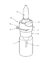
図を参照する。投与装置は投与部材10を有し、投与部材10は図の実施の形態においてはポンプである。当然のことながら、本発明は、いかなるタイプの投与部材(具体的に言えば、さらに、弁)にも適用できる。ポンプは、何らかのタイプ(具体的に言えば、ネジ留め、圧着式、またはスナップ留めのタイプ)の固定リング30を用いて容器1に組み付けることができる。リングは、特定の別個の部品とするか、または装置の一部分と一体化された形で形成することができる。プッシャまたは駆動ヘッド20は、移動によって前記ポンプを駆動することが可能な形でポンプに設けられている。図示された実施の形態において、駆動ヘッドは鼻用のプッシャで、当該プッシャは、鼻孔に差し込むための伸長部24と受けゾーン22とを有し、ユーザは、受けゾーン22を押せば装置を駆動できる。当然のことながら、図示された実施の形態(具体的に言えば、ポンプまたはプッシャのタイプ)は、全く限定的なものではなく、それどころか逆に、本発明はいかなるタイプの流体投与装置にも適用することができる。
Refer to the figure. The dosing device has a
本発明において、装置は駆動ブロック部品40を有し、当該駆動ブロック部品40は、装置に取り外し可能な形で組み付けられている。図1、2、3、6、および図9、10、11に示すブロック状態において、ブロック部品は、具体的に言えば駆動ヘッド20がポンプに対し移動するのを防ぐことにより、ポンプが駆動されないようにしている。図4、5、そして7に示す、部品が抜き取られた状態においては、ポンプは駆動し得る。ブロック位置において、ブロック部品40は、好ましい構成として、図1および10に示すように、駆動ヘッド20に組み付けられている。駆動ヘッドは、穴21を少なくとも1つ有し、ブロック部品40は当該穴21を通して固定リング30と協働するよう作られている。このように、ブロック部品は、前記固定リングに固定または固着された部品とも協働することができる。
In the present invention, the device has a
効果的な構成として、ブロック部品40は、初回の使用を示す働きをする手段をさらに有し、それによって、ブロック部品40が既にそのブロック位置から取り外し済みかどうかが分かる。
効果的な構成として、ブロック部品40は、投与部材10の縦軸を横断する方向に移動が可能である。ブロック部品を握るためのグリップ手段43が少なくとも1つあり、それによって、ユーザがブロック部品を駆動ヘッドの所定位置に入れる操作や、そこから取り出す操作が容易になる。
As an advantageous configuration, the
As an effective configuration, the
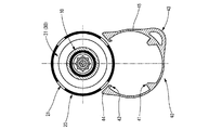
第1の実施の形態において、ブロック部品40は弾性変形可能な開リング45を有し、ヘッド20の周囲に組み付けることができる。図5は、開リング45を、ヘッド20に設置する前の状態で示す図である。この実施の形態において、開リング45は2つのブロック用突起部分41を有し、リングの各端部エッジ44には、折ることのできる部品42を設けることができる。折ることのできる部品42は初回の使用を示す働きをする。2つの突起部分と2つの折ることのできる部品とは、開リング45の内側に向かって突き出ている。
In the first embodiment, the
リング45は、ヘッドへ組み付けられた後(すなわち、ブロック状態において)、かつ投与装置が初回に使用される前は、図6に概略的に示すとおり、駆動ヘッド20の少なくとも一部を囲む形に延びている。図示された実施の形態において、駆動ヘッドの側壁は4つの穴を有し、そのうち2つは、ブロック状態において前記ブロック用突起部分41を収容し、他の2つは、ブロック状態、かつ初回の使用前において前記折ることのできる部品42を収容する。当然のことながら、本発明は、図示された実施の形態に限定されるものではなく、ブロック用突起部分および/あるいは折ることのできる部品、そしてそれらに対応する駆動ヘッドの穴の数を変えることも考えられる。
The
図3および6に示すように、ブロック状態において、ブロック部品は、ブロック用突起部分41を介して、固定リング30の上面またはリム31(あるいは、それに固着された部品)と、駆動ヘッド20の穴21との両方と協働して、ヘッド20がリング30に対し軸方向に移動するのを防ぐ。ブロック用突起部分41は、開リング45の周囲から、ヘッドの穴21を通り、固定リング30のリム31まで、ヘッド20と固定リング30との間のスライド軸に垂直な方向に延びている。
As shown in FIGS. 3 and 6, in the block state, the block component is inserted into the upper surface of the fixing
リングの各端部エッジ44に置かれた2つの折ることのできる部品42は、初回の使用時(すなわち、ブロック部品40がブロック位置から初めて取り外される際)に、折れるか、または変形するように作られている。図5および6に示すように、折ることのできる部品は、2つのタブ42で形成することができる。タブは、本実施の形態においては、ヘッドの穴21のエッジと以下の形で協働する。その形とは、ユーザがブロック部品40を取り外すと、その結果、当該タブはブロック部品から切り離される、というものである。そのため、損傷のないタブ42の存在は、ユーザに、ブロック部品はまだ一度もブロック位置から取り外されたことがないことを保証する。そうして、装置は全くの未駆動であることが確実となる。
The two
初回使用後は、開リング45を所定のブロック位置に入れ直すことができる。ユーザは、開リングを駆動ヘッド20の周囲にスナップ留めするだけでよい。スナップ留めは、2つの端部44のエッジの形状により容易になっている。図5に示すように、2つの端部エッジ44は、駆動ヘッド20と接触させられる際は、ヘッドの円形の壁の接線に実質的に沿った形となる。これにより、リングの端部をヘッドの周囲に沿ってスライド移動させて最後にスナップ留めするのが容易になる。また、リングの端部のエッジの本形状は、スナップ留めする操作と外す操作とを連続して行っていても駆動ヘッドが壊れないという効果を示す。そうして、開リングは、スナップ留めされると再び駆動ヘッドの少なくとも一部を囲む形に延び、各ブロック用突起部分41は、駆動ヘッドの穴21のいずれかを通って固定リングまたは当該固定リングに固着された部品と協働して、ポンプが駆動しないようにする。
After the first use, the
効果的な構成として、ブロック部品はプラスチック材料で作られている。このプラスチック材料は、強度と変形性との両方を備えており、ブロック部品を再利用できる一方で、ブロック部品をスナップ留め/外しできる。ただし、他の材料を考えることもできる。
効果的な構成として、図示された駆動ヘッドの4つの穴21は、投与部材(厳密に言えば、図示された実施の形態においては、ポンプ)の縦軸を中心として対称に分散配置されている。また、効果的な構成として、駆動ヘッドの4つの穴と協働するよう作られた2つのブロック用突起部分41および2つのタブ42も、リングの中心に対し対称となる形で開リング上に置かれている。これにより、本発明のブロック部品40は、駆動ヘッドにいずれの側面からでも係合させることができる。本実施の形態は簡単かつ素早く組み立てられる。というのも、ブロック部品をヘッドに組み付ける際、駆動ヘッドごとに方向を決める必要がないためである。加えて、ユーザは、1回使用するたびに極めて容易にブロック部品を所定位置に入れ直すことができる。リングをスナップ留めしてから、必要であればヘッドの周囲でわずかに回転させるだけで、ブロック用突起部分を駆動ヘッドのいずれかの穴にはめることができる。
As an effective construction, the block part is made of a plastic material. This plastic material has both strength and deformability and allows the block parts to be reused while the block parts can be snapped / unscrewed. However, other materials can be considered.
As an effective configuration, the four
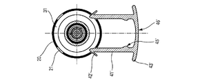
第2の実施の形態におけるブロック部品は、2本の実質的に並行なブランチ41’を有し、当該2本のブランチ41’が2つのブロック用突起部分を成す。ブロック部品は、図7乃至9に示すようにU字形状を呈している。ブロック部品の2本の並行なブランチ41’を相互接続する横断方向の壁46’を前記ブランチの根の部分の両側から張り出した形とすることで、グリップ手段43’を形成することもできる。ブランチの自由端44’はそれぞれ、折ることのできる部品42’を有し、当該部品42’は、図に示す本実施の形態においてはタブで形成されている。第1の実施の形態と同様に、駆動ヘッド20は4つの穴21を有し、当該穴21は、ヘッドの縦軸を中心として対称に配置されている。各ブランチ41’は、ブロック位置への組み付け中、第1の穴21を通ってヘッド20の内部に差し込まれ、投与部材10とヘッドの内壁との間に位置する空間を通過して、第2の穴21を通ってヘッドの外へ出る。そのため、各ブランチは、ブロック状態において、駆動ヘッドの2つの穴と、固定リング30のリム31(あるいは、それに固着された部品)との両方と、駆動軸に対して垂直な方向で協働する。初回の使用の前は、折ることのできる部品はそれぞれ、穴のエッジと協働している。ブロック部品を初めて取り外している際中、タブ42’は、それぞれの前記第2の穴21のエッジにより駆動ヘッドの外側に保持された状態なので、当該第2の穴21のエッジに当たって壊れる。本実施の形態において、折ることのできる部品42’は、ヘッドの外側に位置し、直接目に見える初回使用インジケータを成すという効果を示す。以降の使用の際には、ブランチを固定リング30のリム31の上でスライド移動させて、U字形のブロック部品を2つの穴を介してヘッドに容易に係合させることができる。変形例においては、初回の使用後、したがって初回使用のインジケータ手段が欠けた状態では、ブロック部品を第2の穴を通してヘッドから外に出す必要はない。
The block component in the second embodiment has two substantially
効果的な構成として、ブロック部品は保持手段によりブロック位置に保持され、それにより、当該ブロック部品が駆動ヘッドから極めて容易に取れてしまう事態は防止される。保持手段は、弾性変形が可能である。第1の実施の形態と同様に、保持手段は開リング45で成り、駆動ヘッド20の外周面と協働することにしてもよい。別の形として、保持手段は、図9に示すように、ブロック用突起部分41’に位置した少なくとも1つの保持用突起部分45’で成る、という形にすることもできる。図9には2つの保持用突起部分45’が示されており、これらは、2つのブロック用突起部分41’のそれぞれにショルダー2つを対称となる形で形成している。保持用突起部分はそれぞれ駆動ヘッド20の内壁と協働して、一種のスナップ留めの状態を作り、ブロック部品が駆動ヘッドの外に出るのを防ぐ。ブロック部品を取り外すには、ユーザは前記保持用突起部分の保持力を上回る閾値けん引力を加えなければならない。保持手段により、ブロック部品はブロック位置に保たれ、それにより、偶然に駆動する危険なく投与装置を安全に持ち運ぶことができる。
As an effective configuration, the block component is held at the block position by the holding means, thereby preventing the block component from being easily removed from the drive head. The holding means can be elastically deformed. Similar to the first embodiment, the holding means may be an
いずれの実施の形態であっても、本発明のブロック部品は、効果的な構成としていかなる既存の流体投与装置にも適用でき、装置に加えなければならない唯一の変更は、駆動ヘッドに穴を開けることのみである。
ここまで、本発明について、2つの効果的な実施の形態を参照しながら説明してきたが、当然のことながら、本発明は図示した実施の形態に限定されるものではない。当業者であれば、添付の特許請求の範囲によって規定される本発明の範囲を逸脱しない形で、変形例を考案することが可能である。
In any embodiment, the block component of the present invention can be applied to any existing fluid dispensing device as an effective configuration, the only change that must be made to the device is to puncture the drive head It is only that.
So far, the present invention has been described with reference to two effective embodiments, but it should be understood that the present invention is not limited to the illustrated embodiments. Those skilled in the art can devise variations without departing from the scope of the invention as defined by the appended claims.
Claims (13)
手動で駆動されるポンプまたは弁という流体投与部材(10)であって、固定リング(30)により容器(1)に固定される、という前記流体投与部材と、
前記流体投与部材に配置され、移動することで前記流体投与部材を駆動することが可能な駆動ヘッド(20)と、
ブロック位置において、流体投与部材が駆動しないようにする取り外し可能なブロック部品(40)と、を有し、
前記ブロック部品は、少なくとも1つのブロック用突起部分(41)を有して、駆動ヘッドに組み付けられており、
当該ブロック用突起部分(41)が、前記駆動ヘッドに設けられた少なくとも1つの穴(21)を通ることにより、固定リングまたは当該固定リングに固着された部品と協働する
ことを特徴とする流体投与装置。A fluid administration device comprising:
A fluid delivery member (10), manually driven pump or valve, said fluid delivery member being secured to the container (1) by a retaining ring (30);
Wherein arranged in the fluid dispensing member, and the movement can drive head to drive the fluid delivery member by (20),
A removable block part (40) that prevents the fluid dispensing member from being driven in the block position;
Before Symbol block component is at least one block protrusion portion (41), is assembled to the drive head,
The block projections portion (41) is, at least one hole (21) for passing Rukoto provided in the drive head, characterized in that it cooperates with the anchored component fixing ring or the fixing ring Fluid dosing device .
を特徴とする請求項1に記載の流体投与装置。The block part (40) is movable in a translational manner in a direction transverse to the longitudinal axis of the fluid delivery member (10);
The fluid administration device according to claim 1.
を特徴とする請求項1または2に記載の流体投与装置。The block part (40) has at least one foldable part (42), the foldable part (42) being made to break when the block part is first removed from the block position. Being
The fluid administration device according to claim 1 or 2 .
を特徴とする請求項3に記載の流体投与装置。The at least one foldable part (42) is formed of a tab, the tab cooperating with at least one edge of the at least one hole (21);
The fluid administration device according to claim 3 .
を特徴とする請求項3または4に記載の流体投与装置。The drive head (20) has at least two holes (21), of which at least one hole has a blocking projection (41), and at least one hole has a foldable part (42). Being housed,
The fluid administration device according to claim 3 or 4 , characterized by the above-mentioned.
を特徴とする請求項1乃至5のいずれかに記載の流体投与装置。The block component (40) extends at least partially surrounding the drive head (20) in the block position;
A fluid administration device according to any one of claims 1 to 5 .
を特徴とする請求項6に記載の流体投与装置。The block part has an open ring (45), the open ring (45) has two block projections (41) and folds on each end edge (44) of those parts (41). The drive head has four holes (21), two of which have block projections (41) at the block position, two of which have The foldable part (42) is received at the block position and before the first use,
The fluid administration device according to claim 6 .
を特徴とする請求項5または6に記載の流体投与装置。The block part has two substantially parallel branches (41 '), on which two block projections are formed, each free end of the branch being a foldable part (42' ) And the drive head has four holes (21), and each branch enters the inside of the drive head (20) through the first hole (21) in the block position, and the second hole ( 21) are out of the drive head through and each foldable part (42 ') cooperates with the second hole (21) in the block position and prior to the first use. about,
The fluid administration device according to claim 5 or 6 .
を特徴とする請求項1乃至8のいずれかに記載の流体投与装置。The block component is held in the block position by the holding means (45, 45 ′), and the holding means can be elastically deformed,
A fluid administration device according to any one of claims 1 to 8 .
を特徴とする請求項9に記載の流体投与装置。The holding means is formed by the open ring (45) and cooperates with the peripheral surface of the drive head (20);
The fluid administration device according to claim 9 .
を特徴とする請求項9に記載の流体投与装置。The holding means is formed of at least one holding projection (45 ′) and cooperates with at least one hole (21) of the drive head;
The fluid administration device according to claim 9 .
を特徴とする請求項1乃至11のいずれかに記載の流体投与装置。In the block position, the block part (40) cooperates with the upper surface (31) of the fixing ring (30) or the part fastened to the ring;
The fluid administration device according to any one of claims 1 to 11 .
を特徴とする請求項1乃至12のいずれかに記載の流体投与装置。The block part has at least one grip means (43, 43 ′);
The fluid administration device according to any one of claims 1 to 12 .
Applications Claiming Priority (3)
| Application Number | Priority Date | Filing Date | Title |
|---|---|---|---|
| FR0654401A FR2907434B1 (en) | 2006-10-20 | 2006-10-20 | DEVICE FOR DISPENSING FLUID PRODUCT. |
| FR0654401 | 2006-10-20 | ||
| PCT/FR2007/052149 WO2008047032A2 (en) | 2006-10-20 | 2007-10-15 | Device for dispensing a fluid product |
Publications (2)
| Publication Number | Publication Date |
|---|---|
| JP2010506808A JP2010506808A (en) | 2010-03-04 |
| JP5149906B2 true JP5149906B2 (en) | 2013-02-20 |
Family
ID=38050165
Family Applications (1)
| Application Number | Title | Priority Date | Filing Date |
|---|---|---|---|
| JP2009532858A Expired - Fee Related JP5149906B2 (en) | 2006-10-20 | 2007-10-15 | Fluid dosing device |
Country Status (8)
| Country | Link |
|---|---|
| US (1) | US8104643B2 (en) |
| EP (1) | EP2094585B1 (en) |
| JP (1) | JP5149906B2 (en) |
| CN (1) | CN101547846B (en) |
| AT (1) | ATE481337T1 (en) |
| DE (1) | DE602007009303D1 (en) |
| FR (1) | FR2907434B1 (en) |
| WO (1) | WO2008047032A2 (en) |
Families Citing this family (24)
| Publication number | Priority date | Publication date | Assignee | Title |
|---|---|---|---|---|
| ITRM20070241A1 (en) * | 2007-04-24 | 2008-10-25 | Emsar Spa | CONNECTION DEVICE FOR BOTTLE MICROPUMPS. |
| EP2077132A1 (en) | 2008-01-02 | 2009-07-08 | Boehringer Ingelheim Pharma GmbH & Co. KG | Dispensing device, storage device and method for dispensing a formulation |
| IT1395574B1 (en) * | 2009-09-14 | 2012-10-16 | Guala Dispensing Spa | DISTRIBUTION DEVICE |
| WO2011064163A1 (en) | 2009-11-25 | 2011-06-03 | Boehringer Ingelheim International Gmbh | Nebulizer |
| US10016568B2 (en) | 2009-11-25 | 2018-07-10 | Boehringer Ingelheim International Gmbh | Nebulizer |
| EP2585151B1 (en) * | 2010-06-24 | 2018-04-04 | Boehringer Ingelheim International GmbH | Nebulizer |
| DE102010048085A1 (en) * | 2010-10-04 | 2012-04-05 | Ing. Erich Pfeiffer Gmbh | discharge |
| US9095466B2 (en) * | 2010-11-16 | 2015-08-04 | W. L. Gore & Associates, Inc. | Apposition fiber for use in endoluminal deployment of expandable devices in tortuous anatomies |
| WO2013152894A1 (en) | 2012-04-13 | 2013-10-17 | Boehringer Ingelheim International Gmbh | Atomiser with coding means |
| FR2989598B1 (en) * | 2012-04-24 | 2016-01-01 | Lablabo | DEVICE FOR PACKAGING AND DISPENSING FLUID PRODUCTS WITH A MANUAL PUMP. |
| EP2920087A4 (en) * | 2012-11-14 | 2016-11-23 | Meadwestvaco Corp | Child resistant pumps |
| US20140263456A1 (en) * | 2013-03-15 | 2014-09-18 | Launce R. Barber | Child-resistant closure systems for containers |
| US20140263457A1 (en) | 2013-03-15 | 2014-09-18 | Launce R. Barber | Child-resistant closure systems for containers |
| US9950844B2 (en) | 2013-03-15 | 2018-04-24 | Taptango, Llc | Child-resistant closure systems for containers |
| ES2836977T3 (en) | 2013-08-09 | 2021-06-28 | Boehringer Ingelheim Int | Nebulizer |
| GB2519173A (en) * | 2013-10-14 | 2015-04-15 | Corigo Ab | Locking device for a nasal sprayer |
| US10085729B2 (en) * | 2014-03-06 | 2018-10-02 | Ethicon, Inc. | Methods and devices for forming biomedical coatings using variable mixing ratios of multi-part compositions |
| DE102016105998A1 (en) * | 2015-09-23 | 2017-03-23 | Rpc Bramlage Gmbh | Dispensers for liquid to pasty masses |
| USD937687S1 (en) | 2018-06-29 | 2021-12-07 | Aptar Radolfzell Gmbh | Dispenser |
| USD881716S1 (en) * | 2018-06-29 | 2020-04-21 | Aptar Radolfzell Gmbh | Packaging bottle for liquids |
| USD933494S1 (en) | 2018-07-10 | 2021-10-19 | Aptar Radolfzell Gmbh | Packaging bottle for liquids |
| USD889278S1 (en) * | 2018-12-28 | 2020-07-07 | Aptar Radolfzell Gmbh | Packaging bottle for liquids |
| US10737875B1 (en) * | 2020-01-23 | 2020-08-11 | Four Strong IP, LLC | Closure assembly for use with a container |
| CN116848349A (en) | 2021-02-08 | 2023-10-03 | 考尔得产品公司 | Fluid coupling |
Family Cites Families (13)
| Publication number | Priority date | Publication date | Assignee | Title |
|---|---|---|---|---|
| US4377106A (en) * | 1980-06-30 | 1983-03-22 | Realex Corporation | Tamper-resistant locking clip for dispensing pumps |
| US4424919A (en) * | 1981-10-28 | 1984-01-10 | Diamond International Corporation | Dispenser having plunger locking means |
| US4582228A (en) * | 1982-02-04 | 1986-04-15 | Diamond Aerosol Corporation | Irritant aerosol spray |
| US5284264A (en) * | 1992-09-03 | 1994-02-08 | Aptargroup, Inc. | Toggle-action dispensing closure with slide lock |
| JP3808206B2 (en) * | 1998-04-30 | 2006-08-09 | 株式会社吉野工業所 | Aerosol jet |
| DE19819748A1 (en) * | 1998-05-02 | 1999-11-04 | Pfeiffer Erich Gmbh & Co Kg | Media Donor |
| DE19942792A1 (en) * | 1999-09-08 | 2001-03-15 | Pfeiffer Erich Gmbh & Co Kg | Media Donor |
| US6186365B1 (en) * | 2000-03-22 | 2001-02-13 | Calmar Inc. | Pump sprayer with slide lock |
| JP4135167B2 (en) * | 2000-10-30 | 2008-08-20 | 株式会社吉野工業所 | Dispensing container |
| FR2830522B1 (en) * | 2001-10-04 | 2004-02-13 | Tebro | SIDE-OPERATED FLUID PRODUCT DISPENSING DEVICE |
| US20070023452A1 (en) * | 2005-08-01 | 2007-02-01 | Living Fountain Plastic Industrial Co., Ltd. | Safeguard device for a liquid container pump |
| US20070080173A1 (en) * | 2005-10-06 | 2007-04-12 | Coe Matthew T | Fluid dispenser with a safety dispensing actuator |
| US20070102449A1 (en) * | 2005-11-10 | 2007-05-10 | Living Fountain Plastic Industrial Co., Ltd. | Anti-foreign object structure for a liquid container pump |
-
2006
- 2006-10-20 FR FR0654401A patent/FR2907434B1/en active Active
-
2007
- 2007-10-15 US US12/446,151 patent/US8104643B2/en active Active
- 2007-10-15 WO PCT/FR2007/052149 patent/WO2008047032A2/en active Application Filing
- 2007-10-15 EP EP07858576A patent/EP2094585B1/en active Active
- 2007-10-15 AT AT07858576T patent/ATE481337T1/en not_active IP Right Cessation
- 2007-10-15 CN CN2007800448849A patent/CN101547846B/en not_active Expired - Fee Related
- 2007-10-15 DE DE602007009303T patent/DE602007009303D1/en active Active
- 2007-10-15 JP JP2009532858A patent/JP5149906B2/en not_active Expired - Fee Related
Also Published As
| Publication number | Publication date |
|---|---|
| CN101547846B (en) | 2011-12-28 |
| EP2094585B1 (en) | 2010-09-15 |
| FR2907434B1 (en) | 2009-01-09 |
| CN101547846A (en) | 2009-09-30 |
| WO2008047032A3 (en) | 2008-06-19 |
| US20100206908A1 (en) | 2010-08-19 |
| DE602007009303D1 (en) | 2010-10-28 |
| FR2907434A1 (en) | 2008-04-25 |
| WO2008047032A2 (en) | 2008-04-24 |
| ATE481337T1 (en) | 2010-10-15 |
| JP2010506808A (en) | 2010-03-04 |
| EP2094585A2 (en) | 2009-09-02 |
| US8104643B2 (en) | 2012-01-31 |
Similar Documents
| Publication | Publication Date | Title |
|---|---|---|
| JP5149906B2 (en) | Fluid dosing device | |
| JP5066187B2 (en) | Fluid dispenser device | |
| JP4764587B2 (en) | Safety cap | |
| US8286832B2 (en) | Dispensing device for single use | |
| AU2003246358B2 (en) | Catheter insertion device | |
| JP4809350B2 (en) | Fixed element | |
| ES2909969T3 (en) | Catheter devices with needle guards and related methods | |
| EP2458230B1 (en) | Clip | |
| US8870030B2 (en) | Attachment mechanism for a container | |
| US20150158659A1 (en) | Attachment mechanism for a container | |
| JP6231843B2 (en) | Misfueling prevention device | |
| US20050016626A1 (en) | Transfer device and cap assembly for use with a container and the transfer device | |
| EP2311753A2 (en) | Trigger actuator for aerosol container to aid in actuating same | |
| US10632487B2 (en) | Fluid dispenser | |
| JP2008525076A (en) | Fluid dispenser | |
| JP2008512285A5 (en) | ||
| US20180133731A1 (en) | Discharge head for a dispenser for discharging a fluid and dispenser comprising a discharge head of this type and securing section for a discharge head of this type | |
| US11419989B2 (en) | Removal member for removing a needle protective cap | |
| WO2002055321A3 (en) | Wheel cap for a vehicle wheel | |
| US8002149B2 (en) | Child resistant closure | |
| JP4813354B2 (en) | Fluid dispenser head | |
| CN113039368B (en) | Fastener and fixing assembly comprising such a fastener | |
| CN111315493A (en) | Connection system between the head of a trigger dispenser and a bottle | |
| KR200412392Y1 (en) | A container for aromatics | |
| US9126746B2 (en) | Adaptor for spray cans |
Legal Events
| Date | Code | Title | Description |
|---|---|---|---|
| A621 | Written request for application examination |
Free format text: JAPANESE INTERMEDIATE CODE: A621 Effective date: 20100830 |
|
| A977 | Report on retrieval |
Free format text: JAPANESE INTERMEDIATE CODE: A971007 Effective date: 20120614 |
|
| A131 | Notification of reasons for refusal |
Free format text: JAPANESE INTERMEDIATE CODE: A131 Effective date: 20120703 |
|
| A521 | Request for written amendment filed |
Free format text: JAPANESE INTERMEDIATE CODE: A523 Effective date: 20120921 |
|
| TRDD | Decision of grant or rejection written | ||
| A01 | Written decision to grant a patent or to grant a registration (utility model) |
Free format text: JAPANESE INTERMEDIATE CODE: A01 Effective date: 20121113 |
|
| A61 | First payment of annual fees (during grant procedure) |
Free format text: JAPANESE INTERMEDIATE CODE: A61 Effective date: 20121130 |
|
| R150 | Certificate of patent or registration of utility model |
Free format text: JAPANESE INTERMEDIATE CODE: R150 |
|
| FPAY | Renewal fee payment (event date is renewal date of database) |
Free format text: PAYMENT UNTIL: 20151207 Year of fee payment: 3 |
|
| LAPS | Cancellation because of no payment of annual fees |