JP4809350B2 - Fixed element - Google Patents
Fixed element Download PDFInfo
- Publication number
- JP4809350B2 JP4809350B2 JP2007528594A JP2007528594A JP4809350B2 JP 4809350 B2 JP4809350 B2 JP 4809350B2 JP 2007528594 A JP2007528594 A JP 2007528594A JP 2007528594 A JP2007528594 A JP 2007528594A JP 4809350 B2 JP4809350 B2 JP 4809350B2
- Authority
- JP
- Japan
- Prior art keywords
- fixing element
- support wall
- fixing
- opening
- plate
- Prior art date
- Legal status (The legal status is an assumption and is not a legal conclusion. Google has not performed a legal analysis and makes no representation as to the accuracy of the status listed.)
- Expired - Fee Related
Links
- 239000000758 substrate Substances 0.000 claims description 28
- 239000002184 metal Substances 0.000 claims description 3
- 239000011347 resin Substances 0.000 claims description 2
- 229920005989 resin Polymers 0.000 claims description 2
- 238000004873 anchoring Methods 0.000 description 3
- 238000000034 method Methods 0.000 description 3
- 238000005452 bending Methods 0.000 description 1
- 230000001419 dependent effect Effects 0.000 description 1
- 230000000694 effects Effects 0.000 description 1
- 238000003780 insertion Methods 0.000 description 1
- 230000037431 insertion Effects 0.000 description 1
- 238000012986 modification Methods 0.000 description 1
- 230000004048 modification Effects 0.000 description 1
Images


Classifications
-
- F—MECHANICAL ENGINEERING; LIGHTING; HEATING; WEAPONS; BLASTING
- F16—ENGINEERING ELEMENTS AND UNITS; GENERAL MEASURES FOR PRODUCING AND MAINTAINING EFFECTIVE FUNCTIONING OF MACHINES OR INSTALLATIONS; THERMAL INSULATION IN GENERAL
- F16B—DEVICES FOR FASTENING OR SECURING CONSTRUCTIONAL ELEMENTS OR MACHINE PARTS TOGETHER, e.g. NAILS, BOLTS, CIRCLIPS, CLAMPS, CLIPS OR WEDGES; JOINTS OR JOINTING
- F16B5/00—Joining sheets or plates, e.g. panels, to one another or to strips or bars parallel to them
- F16B5/06—Joining sheets or plates, e.g. panels, to one another or to strips or bars parallel to them by means of clamps or clips
- F16B5/0607—Joining sheets or plates, e.g. panels, to one another or to strips or bars parallel to them by means of clamps or clips joining sheets or plates to each other
- F16B5/0621—Joining sheets or plates, e.g. panels, to one another or to strips or bars parallel to them by means of clamps or clips joining sheets or plates to each other in parallel relationship
- F16B5/0642—Joining sheets or plates, e.g. panels, to one another or to strips or bars parallel to them by means of clamps or clips joining sheets or plates to each other in parallel relationship the plates being arranged one on top of the other and in full close contact with each other
-
- B—PERFORMING OPERATIONS; TRANSPORTING
- B60—VEHICLES IN GENERAL
- B60R—VEHICLES, VEHICLE FITTINGS, OR VEHICLE PARTS, NOT OTHERWISE PROVIDED FOR
- B60R21/00—Arrangements or fittings on vehicles for protecting or preventing injuries to occupants or pedestrians in case of accidents or other traffic risks
- B60R21/02—Occupant safety arrangements or fittings, e.g. crash pads
- B60R21/16—Inflatable occupant restraints or confinements designed to inflate upon impact or impending impact, e.g. air bags
- B60R21/20—Arrangements for storing inflatable members in their non-use or deflated condition; Arrangement or mounting of air bag modules or components
- B60R21/213—Arrangements for storing inflatable members in their non-use or deflated condition; Arrangement or mounting of air bag modules or components in vehicle roof frames or pillars
Landscapes
- Engineering & Computer Science (AREA)
- Mechanical Engineering (AREA)
- General Engineering & Computer Science (AREA)
- Connection Of Plates (AREA)
- Air Bags (AREA)
- Insertion Pins And Rivets (AREA)
Description
本発明は、請求項1の前段部分に基づく特徴を有する固定要素に関する。 The present invention relates to a fastening element having features based on the front part of claim 1.
この種の固定要素は、国際特許出願WO02/28690A1の明細書において開示されている。この固定要素は、固定クリップによって構成され、これを用いて、固定対象としてのエアバッグが支持壁の外側、例えば車両の車体部分に固定可能である。請求項において、固定用の固定クリップは、支持壁の開口部に係合する。この目的のため、固定クリップは、支持壁の開口部に挿入可能であり、開口部を貫通し、固定クリップの挿入時に所定の終位置に到達するとロックが掛かり、その結果固定クリップが支持壁の開口部から抜けることを防止するように構成されている。ロッキングのために、固定クリップは、スナップ式要素および停止要素を有する。固定要素がロックされた状態では、停止要素は支持壁の外側に押圧状に接触する。支持壁の「外側」は、固定されるべき部材、即ちエアバッグが位置する側という意味で理解される。スナップ式要素は、支持壁の別の側、即ち支持壁の裏面で、エアバッグから離間した方の面に位置し、スナップ式要素は固定要素をロックするために支持壁の裏面に押圧状に接触している。
本発明は、特に簡易に取り扱い可能な固定要素を提案することを課題とする。 An object of the present invention is to propose a fixing element that can be handled particularly easily.
本発明に係る目的は、先ず与えられた種類の固定要素を出発点として、請求項1の特徴によって達成される。本発明に係る固定要素の有利な変更例は、従属項に記載される。 The object according to the invention is achieved by the features of claim 1, starting from a fixed element of the given type. Advantageous modifications of the fastening element according to the invention are described in the dependent claims.
本発明に係る請求項は、外部からアクセス可能であり、スナップ式要素をロック解除することによって固定要素の開口部からの引き抜きが可能なロック解除要素が、固定要素のスナップ式要素に連結された構成とされる。 The claims according to the invention are externally accessible and an unlocking element, which can be pulled out of the opening of the fixing element by unlocking the snapping element, is connected to the snapping element of the fixing element It is supposed to be configured.
本発明に係る固定要素の重要な利点は、ロック解除要素の作動によって同時に、固定要素を支持壁から容易に再度取り外すことが可能である点である。故に本発明に係る固定要素は、支持壁に所定の被取付部材を固定するためだけでなく、当該所定の部材を簡易な方法で再度取り外すためにも使用可能であるという理由から、極めて取り扱いが簡易である。 An important advantage of the fastening element according to the invention is that it can be easily removed from the support wall at the same time by actuating the unlocking element. Therefore, the fixing element according to the present invention is extremely easy to handle because it can be used not only for fixing a predetermined mounted member to the support wall but also for removing the predetermined member again by a simple method. It is simple.
本発明に係る固定要素のさらに重要な利点は、ロック解除要素のおかげで、取り外しの過程で支持壁を損傷することなく、固定要素を支持壁から取り外すことが可能である点である。 A further important advantage of the fixing element according to the invention is that thanks to the unlocking element, it is possible to remove the fixing element from the support wall without damaging the support wall during the removal process.
本発明に係る固定要素の第三の重要な利点は、この固定要素が、単に「クリップ式の操作」によって取り付け可能である点である。この固定要素の取り付けには、ネジ等は必要ない。また支持壁の開口部で、糸または他の手段を設ける必要がない。 A third important advantage of the fixing element according to the invention is that it can be attached simply by a “clip-type operation”. No screws or the like are required for attaching the fixing element. There is also no need to provide thread or other means at the opening in the support wall.
ロック解除要素が支持壁の開口部を貫通し、それ故、外側から直接作動することが可能であるならば、ロック解除要素は特に簡易かつ有利に作動することが可能である。 If the unlocking element penetrates the opening of the support wall and can therefore be actuated directly from the outside, the unlocking element can be actuated particularly simply and advantageously.
スナップ式要素は、基板を有することが好ましく、基板は2つの平行または少なくとも概ね平行な側端部を伴い、更にこれら2つの側端部に各々にいずれも連結し支持壁に固定要素を保持するために用いられる保持板を伴う。保持板相互の距離は、基板からの距離が増すにつれて増加することが好ましく、従って、保持板間(側壁間)の距離は基板から離間した方向の終端部では、支持壁開口部の対応する開口端間の距離よりも大きい。故にスナップ式要素は、UまたはV型の側部を形成する2つの保持板によって、断面が概ねU型またはV型である。 The snap-on element preferably has a substrate, the substrate having two parallel or at least generally parallel side ends, each further connected to each of these two side ends and holding a fixing element on the support wall. With a holding plate used for. The distance between the holding plates is preferably increased as the distance from the substrate increases, so that the distance between the holding plates (between the side walls) is the corresponding opening of the support wall opening at the end in the direction away from the substrate. Greater than the distance between the edges. Thus, the snap element is generally U-shaped or V-shaped in cross section with two retaining plates forming U or V-shaped sides.
保持板は、弾性的な構造とされることが好ましく、固定要素が支持壁の開口部に導入される時、開口部の開口端の効果により、保持板間の距離が、開口端(開口部)間の距離に一致する様に、保持板間の距離が縮小されるように、2つの保持板を同時に圧迫可能である。よって2つの保持板は、圧迫されて支持壁の開口部を貫通することが可能である。 The holding plate is preferably made of an elastic structure, and when the fixing element is introduced into the opening portion of the support wall, the distance between the holding plates is set to the opening end (opening portion) due to the effect of the opening end of the opening portion. The two holding plates can be pressed simultaneously so that the distance between the holding plates is reduced to match the distance between the two. Therefore, the two holding plates can be pressed and penetrate the opening of the support wall.
2つの保持板を伴うスナップ式要素の場合、一方のロック解除要素は片側の保持板と相互作用し、他方のロック解除要素は残りの保持板と相互作用するという、2つのロック解除要素が存在することが好ましい。2つの保持板は、2つのロック解除要素によって作動され、固定要素のロック解除を可能とする。 For snap-on elements with two retaining plates, there are two unlocking elements, one unlocking element interacting with one retaining plate and the other unlocking element interacting with the remaining retaining plate It is preferable to do. The two holding plates are actuated by two unlocking elements and allow the locking of the fixing element.
例えばロック解除要素は、基板から離間した方向の各保持板の終端部に連結したタブまたは角度付きの部材によって形成されてもよい。ロック解除要素は、各々に与えられた保持板に一体状に連結されていることが好ましい。 For example, the unlocking element may be formed by a tab or an angled member connected to the end of each holding plate in a direction away from the substrate. The unlocking elements are preferably connected integrally to a retaining plate provided for each.
ロック解除要素は、ロック解除要素が互いに関して同時に圧迫されることによって作動し得るように、保持板上に構成されていることが好ましい。 The unlocking elements are preferably configured on the retaining plate so that the unlocking elements can be actuated by being simultaneously pressed against each other.
スナップ式要素の基板は、正方形または長方形、あるいは少なくとも概ね正方形または概ね長方形の構造であることが好ましい。この場合基板は、基板から派生する保持板の側端部にいずれも鉛直であり、また互いに平行である更なる1組の側端部を有する。連結板は、この更なる1組の側端部の2つの側端部のいずれにもそれぞれ構成されることが好ましい。これらの連結板は、例えば、既に述べた停止要素の停止板の保持に役立てられる。 The substrate of the snap element is preferably a square or rectangle, or at least a generally square or generally rectangular structure. In this case, the substrate has a further set of side edges that are both perpendicular to and parallel to the side edges of the holding plate derived from the substrate. The connecting plate is preferably configured on each of two side end portions of this further set of side end portions. These connecting plates are useful, for example, for holding the stop plates of the stop elements already described.
停止要素は、2つの停止板を有することが好ましく、一方の停止板が一方の連結板に連結し、他方の停止板が他方の連結板に連結する。連結板およびこれに付随する停止板は、いずれも互いに一体状に連結していてもよい。 The stop element preferably has two stop plates, with one stop plate connected to one connecting plate and the other stop plate connected to the other connecting plate. Both the connecting plate and the stop plate associated therewith may be integrally connected to each other.
停止板は特に角度の付いた構造であることが好ましく、その結果、固定要素が定位置に保持される際に、停止板は支持壁の外側を背に、すなわち支持壁の外側上に弾性的に接触する。 The stop plate is preferably a particularly angled structure, so that when the fixing element is held in place, the stop plate is elastic against the outside of the support wall, i.e. on the outside of the support wall. To touch.
角度付きの停止板はいずれも、例えば、支持壁および固定要素の基板に平行な板延展部と、平行な板延展部に関して角度の付いた更なる板延展部を有することが可能である。基板に平行な板延展部は好ましくは、対応する連結板に角度付き板延展部を連結する働きをする。 Any angled stop plate can have, for example, a plate extension parallel to the substrate of the support wall and the fixing element and a further plate extension angled with respect to the parallel plate extension. The plate extension parallel to the substrate preferably serves to connect the angled plate extension to the corresponding connecting plate.
固定要素は、一部品のクリップであり、金属製または樹脂製であることが好ましい。固定要素は、例えば、金属製で打ち抜きおよび曲げ加工によって一部品で形成されてもよい。 The fixing element is a one-piece clip and is preferably made of metal or resin. The fixing element may be made of one piece, for example, made of metal by stamping and bending.
ロック解除要素は、特殊な道具を用いずに取り外し可能であるように構成されていることが好ましい。さらに固定要素は、回転しないような構造であることが好ましい。これは、固定要素が支持壁の開口部において回転できないことを意味する。 The unlocking element is preferably configured to be removable without the use of special tools. Furthermore, it is preferable that the fixing element has a structure that does not rotate. This means that the fixing element cannot rotate at the opening of the support wall.
さらに本発明は、上記した固定要素と、固定要素に連結して車両または車両内部に固定されるエアバッグ・モジュールを有する構造とされ得る。エアバッグ・モジュールは、例えばサイド・エアバッグ・モジュールであってもよい。 Furthermore, the present invention may be a structure having the above-described fixing element and an airbag module connected to the fixing element and fixed to the vehicle or the inside of the vehicle. The airbag module may be, for example, a side airbag module.
本発明は、図に更に詳細に図示される代表的実施例を参照しつつ以下詳述される。 The invention is described in detail below with reference to exemplary embodiments illustrated in more detail in the figures.
図1および2は、固定クリップ型の固定要素を図示する。固定要素10は、停止要素20およびスナップ式要素30を有する。停止要素20およびスナップ式要素30は、図3に概略的に図示される支持壁40に固定要素10を固定するよう作用する。
1 and 2 illustrate a fixing element of the fixing clip type. The
図3では、支持壁40に固定されるべく、支持壁40の開口部50を貫通して、固定要素10が挿入されていることが図示されている。この過程では、スナップ式要素30は、支持壁の開口部50を貫通し充分な深さまで挿入されると、直ちに支持壁40に固定要素10をロックする。
In FIG. 3, it is illustrated that the
ロックされた状態では、停止要素20は、支持壁40の「外側60」に押圧状に接触している。ここで「外側」は、例えばエアバッグまたはエアバッグ・モジュールのような固定されるべき部材が、固定要素10によって取り付けられる、支持壁40の側を意味する。支持壁の他の側70(以下簡略的に背面70と称す)では、スナップ式要素30は、開口部50または支持壁40から固定要素10を引き抜くことができないように、支持壁40に押圧的に接触している。
In the locked state, the
前述の固定要素による支持壁40への被着部材の固定は、図4に概略的に図示されている。固定されるべき所定の部材(被着部材)は、参照番号80によって示され、支持壁40の前側60に位置し、固定要素20によって支持壁40にクランプされる。
The fixing of the adherend to the
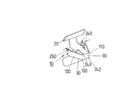
図1〜4に見られるように、スナップ式要素30は、概ね長方形の基板90を有する。2つの保持板120および130は、基板90の2つの平行な側端部100および110上に一体状に成形される。2つの保持板120および130の互いからの位置は、保持板120および130の基板からの距離が増すにつれて増加する。したがって断面では、基板90および2つの保持板(ロック板)120および130は、概ねV型である。2つの保持板120および130の間の上側の距離Aは、支持壁40の開口部50の幅Bより大きいように寸法決めされている。すなわち、A>Bの関係とされている。
As can be seen in FIGS. 1-4, the snap-on
基板90の断面は、支持壁40の開口部50より小さいか、または最大でも開口部50と同じ大きさであるように選択される。従って先ず、基板90と共に固定要素10を開口部50に容易に挿入することが可能である。開口部50への固定要素10のこのような挿入によって、2つの保持板120および130は、2つの開口端部160および170に押圧状に接触する。その結果、固定要素10が開口部50に挿入されている間、基板90によって弾性的または柔軟に保持されている2つの保持板120および130は、共に屈曲される。
The cross section of the
2つの保持板120および130が支持壁40の開口部50を完全に通過して所定の終位置に到達すると直ちに、2つの保持板120および130は、スナップ式にかい離し、開口部50に固定要素10のロッキングを生じる。それゆえ2つの保持板120および130は、スナップ式要素を形成し、互いからの距離Aのために、固定要素10が開口部50から引き抜かれることを防止する。
As soon as the two holding
支持壁40の背面側70への固定要素10の固定がスナップ式要素30によるものである一方、支持壁40の前側60への固定要素10のロッキングは、停止要素20によって起こる。この目的のため、停止要素20は、固定要素10のロッキング用の、支持壁40に弾性的に定着する2つの停止板180および190を有する。
Locking of the fixing
支持壁上へのこの弾性的な定着を生じるために、2つの停止板180および190は、いずれも角度の付いた構造をとる。2つの停止板は各々固定要素10の基板90に概ね平行で且つ支持壁40に平行な、板延展部200および210を有する。角度付きの板延展部220および230は各々、2つの平行な板延展部200および210上に、より詳細には、所定の角度を付けて成形される。この角度は、2つの角度付き板延展部220および230が各々、支持壁40および基板90の方向に向くように選択されている。固定要素10が開口部50に挿入されると、2つの保持板120および130が誘導され開口部50を貫通してはじめて、2つの角度付き板延展部220および230は、支持壁40の前側60に押圧状に接触し、弾性的に偏向され、スナップ式にかい離し固定要素10をロックする。故に2つの角度付き板延展部220および230は、支持壁40に固定要素10を安定的に押圧的に接触し、固定要素10の支持壁40上でのガタツキを防止する。
To cause this elastic anchoring on the support wall, the two
特に図1および図2では、2つの角度付きの板延展部220および230が各々、2つの平行な板延展部200および210によって、連結板240および241に連結されていることが容易に理解される。さらに、2つの連結板240および241は、いずれも基板90に、より正確には基板90の平行な側端部242および243に連結している。
1 and 2 in particular, it is readily understood that two
図1から図3ではまた、タブまたはロック解除ブラケット型の各ロック解除要素250または260は、2つの保持板120および130上に成形されている。2つのロック解除ブラケットはいずれも、基板90から離間した方向を向いた2つの保持板120および130の終端部から伸張し、支持壁40の開口部50を通って支持壁の前側60に到り、外部から直ちにアクセス可能(手動操作可能)である。2つのロック解除要素250および260を、例えば手または標準的なペンチを用いて同時に圧迫することによって、2つの保持板120および130は同時に圧迫可能であり、その結果保持板間の距離は、開口部50の2つの開口端部160と170の間の距離Bに一致する。よって固定要素10を開口部50から引き出し、固定要素を支持壁から取り去ることが可能である。
Also in FIGS. 1 to 3, each unlocking
図4に関連して、被着用の所定の部材80を固定するために、当該部材80は穴300を有し、固定要素10は、自身のスナップ式要素30によってこの穴を完全に貫通する。部材80は、2つの停止板180および190によって保持されている。固定要素10による支持壁40への部材80の固定は、図5の断面図および図6の平面図によって再度詳細に示されている。
With reference to FIG. 4, in order to fix a given
図7および8は、2つのロック解除要素250および260を同時に圧迫することによる固定要素10のロック解除を示す。2つの矢印310および320は、ロック解除中の2つのロック解除要素に力を及ぼすために、どのように2つのロック解除要素250および260に力をさせるべきかを示している。固定要素10は図8ではロック解除位置にあることを示す。
FIGS. 7 and 8 show the unlocking of the anchoring
図9から図13に関しては、ここではエアバッグ・モジュールのエアバッグまたは全エアバッグ・モジュールが、固定要素10によって、例えば車両本体である支持物にどのように固定可能であるかが説明されている。従ってエアバッグは、図4による参照番号80によって示される被着部材に対応している。
With reference to FIGS. 9 to 13, it is described here how the airbag module airbag or the entire airbag module can be fixed to a support, for example a vehicle body, by means of the fixing
固定のために、エアバッグ80は、固定用穴300を伴うタブ400を有し、固定要素10は部分的に圧迫されてこれを通過する。固定用穴300の大きさは、固定要素10のスナップ式要素30は通過できるが、停止要素20は大きすぎて穴400を通過できないように選択されている。図10および図11はこのことを詳細に示している。
For fixation, the
更に、図11および図12では、2つの停止要素180および190がスロット410を通ってエアバッグ被覆部に挿入されることにより、2つの停止板180および190がエアバッグ80の更なる固定に使用可能であることが理解される。
Further, in FIGS. 11 and 12, two
図12は、固定要素10が開口部300を通過し、停止要素180および190によってエアバッグ・モジュールの被覆部において吊られた状態となった後のエアバッグ80を示す。図13は、異なる視点から見た、固定要素10およびエアバッグ80を有する構成を示す。
FIG. 12 shows the
図12および13における結果的な構成は、開口部50(図3から8を参照)によって支持壁40に堅固にラッチ可能である。また支持壁40は、例えば自動車車体であってもよい。
The resulting configuration in FIGS. 12 and 13 can be securely latched to the
本発明では、「請求項3に記載の固定要素であって、前記2つの保持板(120、130)の互いからの距離は、前記基板(90)からの距離が増加するにつれて増加し、前記基板(90)から離間した保持板端部における前記保持板(120、130)間の距離は、前記支持壁(40)の前記開口部(50)の対応する開口端部(160、170)間の距離より大きいことを特徴とする固定要素」という態様(態様1)が想到される。According to the present invention, “the fixing element according to claim 3, wherein the distance of the two holding plates (120, 130) from each other increases as the distance from the substrate (90) increases, The distance between the holding plates (120, 130) at the holding plate end separated from the substrate (90) is between the corresponding opening ends (160, 170) of the opening (50) of the support wall (40). The aspect (aspect 1) of the "fixing element characterized by being larger than the distance" is conceivable.
また本発明では、「請求項3または前記態様1に記載の固定要素であって、前記2つの保持板(120、130)は弾性体として構成され、前記固定要素(10)が前記開口部(50)に導入される際、前記保持板(120、130)間の距離(A)が、前記開口部の前記開口端部(160、170)を介して、前記開口端部(160、170)間の距離(B)に一致するように縮小されるよう、前記2つの保持板がともに圧迫されることを特徴とする固定要素」という態様(態様2)が想到される。Further, according to the present invention, “the fixing element according to claim 3 or aspect 1, wherein the two holding plates (120, 130) are configured as elastic bodies, and the fixing element (10) is the opening ( 50), when the distance (A) between the holding plates (120, 130) is passed through the opening end (160, 170) of the opening, the opening end (160, 170). A mode (mode 2) is conceivable, which is a “fixing element characterized in that the two holding plates are pressed together so as to be reduced to coincide with the distance (B) therebetween.
また本発明では、「請求項3、前記態様1、2のいずれかに記載の固定装置であって、2つのロック解除要素(250、260)が存在し、その一方(250)は片方の前記保持板(120)と相互作用し、他方(260)はもう一方の前記保持板(130)と相互作用することを特徴とする固定要素」という態様(態様3)が想到される。Further, according to the present invention, "the fixing device according to claim 3, any one of the first and second aspects, wherein there are two unlocking elements (250, 260), one (250) of which is the one of the above-mentioned A mode (mode 3) is conceivable as a “fixing element characterized in that it interacts with the holding plate (120) and the other (260) interacts with the other holding plate (130)”.
また本発明では、「前記態様3に記載の固定要素であって、前記各ロック解除要素(250、260)は、前記基板(90)から離間した方向の前記保持板(120、130)の端部に連結していることを特徴とする固定要素」という態様(態様4)が想到される。Further, according to the present invention, “the fixing element according to the third aspect, wherein each unlocking element (250, 260) is an end of the holding plate (120, 130) in a direction away from the substrate (90)”. A mode (mode 4) of a “fixing element characterized by being connected to a portion” is conceived.
また本発明では、「前記態様3または4に記載の固定要素であって、前記各ロック解除要素(250、260)は、それぞれに対応する保持板(120,130)と一体状に連結されていることを特徴とする固定要素」という態様(態様5)が想到される。Further, according to the present invention, “the fixing element according to the third or fourth aspect, wherein each of the unlocking elements (250, 260) is integrally connected to a corresponding holding plate (120, 130). The aspect (aspect 5) of "the fixed element characterized by being" is conceived.
10 固定要素または固定クリップ
20 停止要素
30 スナップ式要素
40 支持壁
50 支持壁の開口部
60 支持壁の前面
70 支持壁の後面
80 被着用の所定の部材
90 基板
100、110 側端部
120、130 保持板
160、170 開口部50の開口端部
180、190 停止板
200、210 平行な板延展部
220、230 角度付き板延展部
250、260 ロック解除要素
240、241 連結板
242、243 側端部
300 部材80の開口部
310、320 矢印
400 エアバッグ固定用タブ
410 スロット
DESCRIPTION OF
Claims (13)
前記開口部(50)に挿入される際に、当該開口部を貫通し、所定の終端位置に到達すると前記支持壁(40)にロックし、前記開口部(50)から前記固定要素(10)の引き抜きを防止するように構成され、
ロック状態においては、当該固定要素の停止要素(20)が前記支持壁(40)の外側、すなわち前記支持壁のうち前記所定の部材(80)に面した側の面に押圧状に接触するとともに、当該固定要素のスナップ式要素(30)が、前記支持壁(40)のうち前記所定の部材(80)から離間した側の面に押圧状に接触し、これにより当該固定要素が前記支持壁の両面(60、70)に押圧状に接するように構成されており、
前記支持壁の前記外側からアクセス可能なロック解除要素(250、260)は、前記開口部(50)を貫通し、また前記スナップ式要素(30)に連結されるとともに、前記スナップ式要素(30)のロック解除と、前記固定要素(10)の前記開口部(50)からの引き抜きを可能としていることを特徴とする固定要素。A fixing element that can be inserted into the opening (50) of the support wall to fix a predetermined member to the outside of the support wall,
When inserted into the opening (5 0 ), it penetrates through the opening, and when reaching a predetermined end position, it locks onto the support wall (40) and from the opening (50) to the fixing element (10 ) To prevent pulling out,
In the locked state, the stop element (20) of the fixed element contacts the outside of the support wall (40), that is, the surface of the support wall facing the predetermined member (80) in a pressing manner. The snap-type element (30) of the fixing element contacts the surface of the support wall (40) that is away from the predetermined member (80) in a pressing manner, so that the fixing element is in contact with the support wall. It is comprised so that it may touch on both surfaces (60,70) of press,
Unlocking elements (250, 260) accessible from the outside of the support wall pass through the opening (50) and are connected to the snap-on element (30) and the snap-on element (30). ) And unlocking of the fixing element (10) from the opening (50).
前記スナップ式要素(30)は、平行または少なくとも概ね平行な2つの側端部(100、110)を有する基板(90)を備えるとともに、保持板(120、130)が、当該2つの側端部(100、110)のいずれにも連結し、前記支持壁(40)に前記固定要素を保持するために用いられることを特徴とする固定要素。A fastening element according to claim 1, comprising:
The snap-on element (30) includes a substrate (90) having two side ends (100, 110) that are parallel or at least generally parallel, and a retaining plate (120, 130) is the two side ends. (100, 110) connected to any of the above, and used for holding the fixing element on the support wall (40).
前記基板(90)は、正方形または長方形、または少なくとも概ね正方形または長方形の構造であり、前記保持板(120、130)が派生する前記側端部(100、110)にいずれも鉛直であり、また互いに平行である更なる一組の側端部(242、243)を有することを特徴とする固定要素。A fastening element according to claim 2 ,
The substrate (90) has a square or rectangular structure, or at least a substantially square or rectangular structure, and is perpendicular to the side end (100, 110) from which the holding plate (120, 130) is derived. Fixing element characterized in that it has a further set of side edges (242, 243) which are parallel to each other.
連結板(240、241)は、前記更なる一組の側端部の2つの各側端(242、243)上に構成されていることを特徴とする固定要素。A securing element according to claim 4,
A connecting element (240, 241) is formed on each of the two side edges (242, 243) of the further set of side edges.
前記停止要素(20)は、2つの停止板(180、190)を有し、その一方は片方の前記連結板(240)に連結し、他方は他方の前記連結板(241)に連結していることを特徴とする固定要素。The fixing element according to claim 5,
The stop element (20) has two stop plates (180, 190), one of which is connected to one of the connecting plates (240) and the other is connected to the other connecting plate (241). A fixed element characterized by
前記連結板(240、241)は、対応する前記停止板(180、190)に一体状に連結していることを特徴とする固定要素。A fastening element according to claim 6, comprising:
The connecting plate (240, 241) is integrally connected to the corresponding stop plate (180, 190).
前記停止板(180、190)は、前記固定要素(10)が適所に保持される際に、前記支持壁(40)の前記外側(60)に弾性的に押圧状に接するように角度を付けられていることを特徴とする固定要素。A fixing element according to claim 6 or 7,
The stop plates (180, 190) are angled so as to elastically contact the outer side (60) of the support wall (40) when the fixing element (10) is held in place. Fixed element characterized by being.
前記各停止板(180、190)は、前記支持壁(40)と平行に延在する板状延展部(200、210)を有するとともに、当該板状延展部(200、210)に対して交差する更なる板延展部(220、230)を有することを特徴とする固定要素。A securing element according to claim 8,
Each of the stop plates (180, 190) has a plate-like extension part (200, 210) extending in parallel with the support wall (40), and intersects the plate-like extension part (200, 210). A fixing element characterized in that it has a further plate extension (220, 230).
前記平行な板延展部(200、210)は、前記交差状の板延展部(220、230)を、対応する前記連結板(240、241)に連結することを特徴とする固定要素。A fastening element according to claim 9, comprising:
The parallel plate extending portions (200, 210) connect the intersecting plate extending portions (220, 230) to the corresponding connecting plates (240, 241).
前記固定要素(10)は、単一部品として形成され、好ましくは金属製または樹脂製であることを特徴とする固定要素。A fixing element according to any one of claims 1 to 10,
The fixing element (10) is formed as a single part, preferably made of metal or resin.
前記固定要素は、打ち抜き加工および曲げ加工を施された単一部品であることを特徴とする固定要素。A fixing element according to any one of claims 1 to 10 ,
The fixing element is a single part that has been punched and bent.
Applications Claiming Priority (3)
| Application Number | Priority Date | Filing Date | Title |
|---|---|---|---|
| DE202004014219U DE202004014219U1 (en) | 2004-09-06 | 2004-09-06 | fastener |
| DE202004014219.8 | 2004-09-06 | ||
| PCT/DE2005/001508 WO2006026956A1 (en) | 2004-09-06 | 2005-08-25 | Fixing element |
Publications (3)
| Publication Number | Publication Date |
|---|---|
| JP2008512285A JP2008512285A (en) | 2008-04-24 |
| JP2008512285A5 JP2008512285A5 (en) | 2008-09-18 |
| JP4809350B2 true JP4809350B2 (en) | 2011-11-09 |
Family
ID=33442399
Family Applications (1)
| Application Number | Title | Priority Date | Filing Date |
|---|---|---|---|
| JP2007528594A Expired - Fee Related JP4809350B2 (en) | 2004-09-06 | 2005-08-25 | Fixed element |
Country Status (5)
| Country | Link |
|---|---|
| EP (2) | EP1787031B2 (en) |
| JP (1) | JP4809350B2 (en) |
| CN (2) | CN101761527B (en) |
| DE (2) | DE202004014219U1 (en) |
| WO (1) | WO2006026956A1 (en) |
Families Citing this family (33)
| Publication number | Priority date | Publication date | Assignee | Title |
|---|---|---|---|---|
| US7861384B2 (en) | 2004-09-06 | 2011-01-04 | Takata-Petri Ag | Airbag arrangement and tools |
| DE202004014219U1 (en) * | 2004-09-06 | 2004-11-11 | Takata-Petri (Ulm) Gmbh | fastener |
| DE102006011836B3 (en) * | 2006-03-15 | 2007-10-18 | Autoliv Development Ab | fastener |
| ITTO20060555A1 (en) * | 2006-07-26 | 2008-01-27 | Itw Automotive Italia S R L | SPRING CHECK ELEMENT FOR VEHICLE FINISHING ELEMENTS, IN PARTICULAR SOUNDPROOF PANELS |
| ATE548229T1 (en) * | 2006-07-31 | 2012-03-15 | Johnson Controls Gmbh | VEHICLE ROOF LINING WITH INTEGRATED HEAD SIDE AIRBAG MODULES |
| DE102006040882B4 (en) * | 2006-08-31 | 2012-10-04 | Autoliv Development Ab | Curtain airbag module |
| DE202006020661U1 (en) | 2006-09-07 | 2009-07-30 | Volkswagen Ag | Fixing clip, in particular for fastening an airbag module in a vehicle |
| US7753402B2 (en) * | 2006-10-09 | 2010-07-13 | Key Safety Systems, Inc. | Air bag assembly and clip therefor |
| DE102006061620A1 (en) | 2006-12-27 | 2008-07-03 | Volkswagen Ag | Support wall for holding airbag module in vehicle, has assembly opening with opening width and opening height which differs from each other for introducing mounting clips, where ratio of width to height lies between specific values |
| DE202007004549U1 (en) | 2007-03-23 | 2007-06-28 | Takata-Petri Ag | Fastener to secure a vehicle airbag at a holder, for installation, has pliable sections to pass through the holder opening and reassert to bring limit surfaces against the holder opening to prevent withdrawal |
| DE202007015431U1 (en) * | 2007-10-30 | 2008-12-24 | Takata-Petri Ag | Airbag device for protecting a vehicle occupant |
| DE102007060953A1 (en) * | 2007-12-18 | 2009-06-25 | Fischerwerke Gmbh & Co. Kg | Click-stop device for mounting e.g. air duct, for sanitary, heating, ventilation or air conditioning systems at wall or ceiling, has actuating unit provided at free ends of locking side pieces that are connected with one another by bar |
| US7837225B2 (en) | 2008-05-14 | 2010-11-23 | Illinois Tool Works Inc. | Airbag fastener assembly |
| DE102008032964B4 (en) | 2008-07-09 | 2012-10-04 | Takata-Petri Ag | Airbag arrangement for a vehicle occupant restraint system |
| DE102008034332B4 (en) | 2008-07-23 | 2024-02-08 | Zf Automotive Germany Gmbh | Vehicle occupant protection device |
| DE102010008158A1 (en) | 2010-02-16 | 2011-08-18 | Volkswagen AG, 38440 | Fastening arrangement for fastening a component to a support wall and fastener therefor |
| US9812684B2 (en) | 2010-11-09 | 2017-11-07 | GM Global Technology Operations LLC | Using elastic averaging for alignment of battery stack, fuel cell stack, or other vehicle assembly |
| DE102011004049B4 (en) | 2011-02-14 | 2017-01-19 | TAKATA Aktiengesellschaft | Device for arranging a fastening element on a fastening tab of a gas bag of a vehicle occupant restraint system |
| JP2012247001A (en) * | 2011-05-27 | 2012-12-13 | Nifco Inc | Clip |
| US9863454B2 (en) | 2013-08-07 | 2018-01-09 | GM Global Technology Operations LLC | Alignment system for providing precise alignment and retention of components of a sealable compartment |
| US20150052725A1 (en) * | 2013-08-22 | 2015-02-26 | GM Global Technology Operations LLC | Elastic averaging alignment system and method |
| US9511802B2 (en) | 2013-10-03 | 2016-12-06 | GM Global Technology Operations LLC | Elastically averaged alignment systems and methods |
| US9669774B2 (en) | 2013-10-11 | 2017-06-06 | GM Global Technology Operations LLC | Reconfigurable vehicle interior assembly |
| US9657807B2 (en) | 2014-04-23 | 2017-05-23 | GM Global Technology Operations LLC | System for elastically averaging assembly of components |
| CN104389870B (en) * | 2014-10-27 | 2016-04-27 | 上海纳杰电气成套有限公司 | A kind of arc clamp-type fixer |
| US9758110B2 (en) | 2015-01-12 | 2017-09-12 | GM Global Technology Operations LLC | Coupling system |
| DE102015209111A1 (en) | 2015-03-30 | 2016-10-06 | Volkswagen Aktiengesellschaft | Fastening arrangement for fastening an airbag to a body-side support wall of a vehicle |
| EP3313679B1 (en) * | 2015-06-23 | 2019-02-06 | Mahle International GmbH | Air-conditioning system for a vehicle, in particular rooftop air-conditioning system, and vehicle having an air-conditioning system of said type |
| DE102016120176A1 (en) * | 2016-10-24 | 2018-04-26 | Trw Automotive Gmbh | Airbag module |
| DE102017005352A1 (en) * | 2017-05-29 | 2018-11-29 | A. Raymond Et Cie | Clip for fixing a first element to a second element and device with such a clip |
| US11552590B2 (en) * | 2018-10-08 | 2023-01-10 | The Board Of Regents Of The University Of Oklahoma | System for mounting solar panels |
| CN109707713B (en) * | 2019-01-28 | 2024-02-23 | 包玉龙 | Corner connector for connecting wooden intersecting members |
| EP3754207B1 (en) * | 2019-06-17 | 2022-08-03 | Illinois Tool Works Inc. | Fastening clip |
Citations (4)
| Publication number | Priority date | Publication date | Assignee | Title |
|---|---|---|---|---|
| JP2000344042A (en) * | 1999-06-02 | 2000-12-12 | Toyoda Gosei Co Ltd | Air bag cover |
| JP2001277986A (en) * | 2000-03-31 | 2001-10-10 | Piolax Inc | Clip device for air bag |
| JP2003247517A (en) * | 2002-02-26 | 2003-09-05 | Inoac Corp | Mounting structure of pillar garnish for curtain type air bag and clip |
| JP2004224209A (en) * | 2003-01-23 | 2004-08-12 | Kasai Kogyo Co Ltd | Mounting structure of pillar trim |
Family Cites Families (30)
| Publication number | Priority date | Publication date | Assignee | Title |
|---|---|---|---|---|
| US2300478A (en) | 1939-09-25 | 1942-11-03 | William R Wiley | Clip |
| US2631345A (en) | 1951-06-11 | 1953-03-17 | Illinois Tool Works | Double snap molding clip |
| US2692414A (en) | 1952-05-08 | 1954-10-26 | Illinois Tool Works | Snap-in stud fastener |
| US2698979A (en) | 1954-04-07 | 1955-01-11 | Tinnerman Products Inc | Molding clip or fastener |
| US2863195A (en) | 1955-12-22 | 1958-12-09 | Robert L Brown | Fastener |
| US2885754A (en) | 1956-12-05 | 1959-05-12 | Illinois Tool Works | Snap-in fastener |
| GB848100A (en) | 1957-05-30 | 1960-09-14 | Ft Products Ltd | An improved fastener |
| US3024509A (en) | 1958-07-11 | 1962-03-13 | Production Metal Stamping Comp | Fastening means and method of applying the same |
| US3080629A (en) | 1959-12-16 | 1963-03-12 | Gen Motors Corp | Moulding fastener |
| SE401653B (en) * | 1972-06-21 | 1978-05-22 | Springfix Befestigungstechnik | MOUNTING CLAMP FOR MOLDINGS WITH T-SHAPE ROCK |
| US4728068A (en) * | 1985-08-23 | 1988-03-01 | Ppmd, Inc. | Removable anchors for perforated panel hangers |
| US4630338A (en) | 1985-12-19 | 1986-12-23 | Usm Corporation | Molding clip |
| DE4026922C2 (en) * | 1990-08-25 | 1994-11-03 | Raymond A Fa | Retaining clip for fastening components to carrier plates |
| US5241727A (en) | 1990-12-24 | 1993-09-07 | Samsung Electron Devices Co., Ltd. | Clip for coupling inner shield with frame |
| US5759004A (en) | 1993-04-20 | 1998-06-02 | Panduit Corp. | MLT bent leg pushmount |
| KR200147268Y1 (en) † | 1994-10-25 | 1999-06-15 | 손욱 | Clip for inner shield of crt |
| US5651562A (en) | 1996-02-28 | 1997-07-29 | Trw Inc. | Release mechanism |
| DE19607786C2 (en) * | 1996-03-01 | 2002-11-21 | Harman Audio Electronic Sys | connecting element |
| JPH09265915A (en) | 1996-03-29 | 1997-10-07 | Nec Kansai Ltd | Inner shield coupling clamp |
| CN1120939C (en) † | 1997-04-22 | 2003-09-10 | 伊劳萨工程股份有限公司 | System for fixing accessories to panels and/or self-carrier elements for internal lining of vehicles |
| ES2147493B1 (en) | 1997-06-27 | 2001-03-01 | Mikalor Sa | FIXING HEAD OF TWO SUPERPOSED METAL SHEETS OR GROUP OF THEM TO JOIN BETWEEN YES. |
| DE19812737A1 (en) * | 1998-03-24 | 1999-05-27 | Autoliv Dev | Side impact airbag for motor vehicles |
| JP4225610B2 (en) | 1998-08-27 | 2009-02-18 | 株式会社シブタニ | Member fixture |
| JP2001065517A (en) | 1999-09-01 | 2001-03-16 | Ochiai:Kk | Clip |
| BR0010884A (en) * | 2000-03-24 | 2002-02-19 | Antolin Grupo Ing Sa | Metaloplastic clamp for fixing roofs and vehicle accessories to the vehicle body |
| GB2367537B (en) | 2000-10-03 | 2003-12-03 | Autoliv Dev | Improvements in or relating to an arrangement for mounting an inflatable element |
| CN1317147C (en) | 2001-10-15 | 2007-05-23 | 安托林工程集团股份有限公司 | Accessory fixing system for vehicle interiors |
| US20040049894A1 (en) | 2002-06-24 | 2004-03-18 | Nicholas Jackson | Sheet metal fastening clip |
| DE102004017188B4 (en) | 2004-04-07 | 2006-08-24 | Key Safety Systems, Inc., Sterling Heights | Fastening element for airbag module |
| DE202004014219U1 (en) * | 2004-09-06 | 2004-11-11 | Takata-Petri (Ulm) Gmbh | fastener |
-
2004
- 2004-09-06 DE DE202004014219U patent/DE202004014219U1/en not_active Expired - Lifetime
-
2005
- 2005-08-25 WO PCT/DE2005/001508 patent/WO2006026956A1/en active Application Filing
- 2005-08-25 DE DE502005008248T patent/DE502005008248D1/en active Active
- 2005-08-25 JP JP2007528594A patent/JP4809350B2/en not_active Expired - Fee Related
- 2005-08-25 EP EP05782810.5A patent/EP1787031B2/en not_active Not-in-force
- 2005-08-25 CN CN2009102541665A patent/CN101761527B/en not_active Expired - Fee Related
- 2005-08-25 CN CN200580025804A patent/CN100587278C/en not_active Expired - Fee Related
- 2005-08-25 EP EP09168956.2A patent/EP2123918B1/en not_active Revoked
Patent Citations (4)
| Publication number | Priority date | Publication date | Assignee | Title |
|---|---|---|---|---|
| JP2000344042A (en) * | 1999-06-02 | 2000-12-12 | Toyoda Gosei Co Ltd | Air bag cover |
| JP2001277986A (en) * | 2000-03-31 | 2001-10-10 | Piolax Inc | Clip device for air bag |
| JP2003247517A (en) * | 2002-02-26 | 2003-09-05 | Inoac Corp | Mounting structure of pillar garnish for curtain type air bag and clip |
| JP2004224209A (en) * | 2003-01-23 | 2004-08-12 | Kasai Kogyo Co Ltd | Mounting structure of pillar trim |
Also Published As
| Publication number | Publication date |
|---|---|
| WO2006026956A1 (en) | 2006-03-16 |
| EP1787031B2 (en) | 2015-11-04 |
| EP1787031A1 (en) | 2007-05-23 |
| DE502005008248D1 (en) | 2009-11-12 |
| EP2123918B1 (en) | 2017-05-17 |
| JP2008512285A (en) | 2008-04-24 |
| CN101761527A (en) | 2010-06-30 |
| CN100587278C (en) | 2010-02-03 |
| CN101761527B (en) | 2012-07-18 |
| DE202004014219U1 (en) | 2004-11-11 |
| EP2123918A3 (en) | 2010-05-05 |
| EP2123918A2 (en) | 2009-11-25 |
| CN101002030A (en) | 2007-07-18 |
| EP1787031B1 (en) | 2009-09-30 |
Similar Documents
| Publication | Publication Date | Title |
|---|---|---|
| JP4809350B2 (en) | Fixed element | |
| JP2008512285A5 (en) | ||
| JP5168694B2 (en) | clip | |
| US8245367B2 (en) | Fastener | |
| JP5620922B2 (en) | clip | |
| JP2980587B1 (en) | Fixture | |
| JP4884022B2 (en) | Parts mounting device | |
| JP2008182880A (en) | Cable fastening device | |
| JP2012135180A (en) | Spring clip | |
| US20100134986A1 (en) | Fastening device for electronic modules on a support rail | |
| JP4260159B2 (en) | Mounting structure of vehicle pillar garnish | |
| WO2016171110A1 (en) | Part fixture | |
| JP2011084142A (en) | License plate mounting structure | |
| WO2007013283A1 (en) | Clip | |
| WO2007007687A1 (en) | Clip | |
| WO2015008551A1 (en) | Reinforcement leaf spring for resin clip | |
| JP2007510576A (en) | Unit carrier with integral locking device for vehicle doors | |
| JP4283136B2 (en) | Fixed structure, protector and electrical junction box | |
| KR100374130B1 (en) | attachment for vehicle parts | |
| JP3851133B2 (en) | Clamp | |
| JP4320493B2 (en) | clip | |
| JP2006062648A (en) | Seat belt attachment device | |
| JP4641689B2 (en) | Circuit breaker mounting structure | |
| JP2007110806A (en) | Fixing tool | |
| JP5598042B2 (en) | Elevator car operation panel |
Legal Events
| Date | Code | Title | Description |
|---|---|---|---|
| A521 | Request for written amendment filed |
Free format text: JAPANESE INTERMEDIATE CODE: A523 Effective date: 20080730 |
|
| A621 | Written request for application examination |
Free format text: JAPANESE INTERMEDIATE CODE: A621 Effective date: 20080730 |
|
| A131 | Notification of reasons for refusal |
Free format text: JAPANESE INTERMEDIATE CODE: A131 Effective date: 20110105 |
|
| A521 | Request for written amendment filed |
Free format text: JAPANESE INTERMEDIATE CODE: A523 Effective date: 20110328 |
|
| TRDD | Decision of grant or rejection written | ||
| A01 | Written decision to grant a patent or to grant a registration (utility model) |
Free format text: JAPANESE INTERMEDIATE CODE: A01 Effective date: 20110726 |
|
| A01 | Written decision to grant a patent or to grant a registration (utility model) |
Free format text: JAPANESE INTERMEDIATE CODE: A01 |
|
| A61 | First payment of annual fees (during grant procedure) |
Free format text: JAPANESE INTERMEDIATE CODE: A61 Effective date: 20110818 |
|
| FPAY | Renewal fee payment (event date is renewal date of database) |
Free format text: PAYMENT UNTIL: 20140826 Year of fee payment: 3 |
|
| R150 | Certificate of patent or registration of utility model |
Free format text: JAPANESE INTERMEDIATE CODE: R150 |
|
| R250 | Receipt of annual fees |
Free format text: JAPANESE INTERMEDIATE CODE: R250 |
|
| R250 | Receipt of annual fees |
Free format text: JAPANESE INTERMEDIATE CODE: R250 |
|
| R250 | Receipt of annual fees |
Free format text: JAPANESE INTERMEDIATE CODE: R250 |
|
| R250 | Receipt of annual fees |
Free format text: JAPANESE INTERMEDIATE CODE: R250 |
|
| LAPS | Cancellation because of no payment of annual fees |