JP5146103B2 - Sheet stacking apparatus, sheet processing apparatus, and image forming apparatus - Google Patents
Sheet stacking apparatus, sheet processing apparatus, and image forming apparatus Download PDFInfo
- Publication number
- JP5146103B2 JP5146103B2 JP2008130822A JP2008130822A JP5146103B2 JP 5146103 B2 JP5146103 B2 JP 5146103B2 JP 2008130822 A JP2008130822 A JP 2008130822A JP 2008130822 A JP2008130822 A JP 2008130822A JP 5146103 B2 JP5146103 B2 JP 5146103B2
- Authority
- JP
- Japan
- Prior art keywords
- sheet stacking
- driving
- sheet
- tray
- speed
- Prior art date
- Legal status (The legal status is an assumption and is not a legal conclusion. Google has not performed a legal analysis and makes no representation as to the accuracy of the status listed.)
- Expired - Fee Related
Links
Images


Classifications
-
- B—PERFORMING OPERATIONS; TRANSPORTING
- B65—CONVEYING; PACKING; STORING; HANDLING THIN OR FILAMENTARY MATERIAL
- B65H—HANDLING THIN OR FILAMENTARY MATERIAL, e.g. SHEETS, WEBS, CABLES
- B65H31/00—Pile receivers
- B65H31/04—Pile receivers with movable end support arranged to recede as pile accumulates
- B65H31/08—Pile receivers with movable end support arranged to recede as pile accumulates the articles being piled one above another
- B65H31/10—Pile receivers with movable end support arranged to recede as pile accumulates the articles being piled one above another and applied at the top of the pile
-
- B—PERFORMING OPERATIONS; TRANSPORTING
- B65—CONVEYING; PACKING; STORING; HANDLING THIN OR FILAMENTARY MATERIAL
- B65H—HANDLING THIN OR FILAMENTARY MATERIAL, e.g. SHEETS, WEBS, CABLES
- B65H2511/00—Dimensions; Position; Numbers; Identification; Occurrences
- B65H2511/20—Location in space
-
- B—PERFORMING OPERATIONS; TRANSPORTING
- B65—CONVEYING; PACKING; STORING; HANDLING THIN OR FILAMENTARY MATERIAL
- B65H—HANDLING THIN OR FILAMENTARY MATERIAL, e.g. SHEETS, WEBS, CABLES
- B65H2513/00—Dynamic entities; Timing aspects
- B65H2513/10—Speed
-
- B—PERFORMING OPERATIONS; TRANSPORTING
- B65—CONVEYING; PACKING; STORING; HANDLING THIN OR FILAMENTARY MATERIAL
- B65H—HANDLING THIN OR FILAMENTARY MATERIAL, e.g. SHEETS, WEBS, CABLES
- B65H2553/00—Sensing or detecting means
- B65H2553/60—Details of intermediate means between the sensing means and the element to be sensed
- B65H2553/61—Mechanical means, e.g. contact arms
-
- B—PERFORMING OPERATIONS; TRANSPORTING
- B65—CONVEYING; PACKING; STORING; HANDLING THIN OR FILAMENTARY MATERIAL
- B65H—HANDLING THIN OR FILAMENTARY MATERIAL, e.g. SHEETS, WEBS, CABLES
- B65H2801/00—Application field
- B65H2801/03—Image reproduction devices
- B65H2801/06—Office-type machines, e.g. photocopiers
Description
本発明は、搬送されてきたシート部材を積載するシート積載装置、このシート積載装置
を備え前記シート部材に対して所定の処理を施すシート処理装置、及びこのシート処理装置を一体または別体に備えた複写機、プリンタ、ファクシミリ、これらの機能の少なくとも2つを有するデジタル複合機などの画像形成装置に関する。
The present invention includes a sheet stacking apparatus that stacks conveyed sheet members, a sheet processing apparatus that includes the sheet stacking apparatus and performs predetermined processing on the sheet members, and the sheet processing apparatus that is integrated or separately provided. copying machine, a printer, a facsimile, relates to an image forming equipment such as a digital multifunction peripheral having at least two of these functions.
複写機、プリンタ、ファクシミリ、あるいはデジタル複合機などの画像形成装置の普及に伴い、画像形成後に記録紙、転写紙、OHPシート、その他のシート状記録媒体(本明細書では単に「シート」または「シート部材」とも称する)が大量に排紙される場合がある。そのため、排紙されたシートを受ける排紙トレイは、排紙されたシートの積載量に応じて昇降するように構成され、排紙されたシートの整合性を保持するように構成されている。このような排紙(積載)トレイでは、排紙され、積載されたシートを排紙トレイから大量に抜き出すと、シートの排紙口から排紙トレイの上面あるいは、排紙トレイ上のシート束の上面との距離が開く。距離が大きく開くと、排紙口から排紙されたシートが落下するまでの距離が大きくなり、排紙トレイ上あるいはシート束の上面状に落下する際に整合性が乱れてしまう。そこで、これに対応するために排紙トレイを速やかに上昇させることが要求されている。 With the widespread use of image forming apparatuses such as copying machines, printers, facsimiles, and digital multi-function peripherals, recording paper, transfer paper, OHP sheets, and other sheet-like recording media (in this specification, simply “sheet” or “ In some cases, a large amount of sheet members are also discharged. Therefore, a paper discharge tray that receives the discharged sheets is configured to move up and down according to the stack amount of the discharged sheets, and is configured to maintain the consistency of the discharged sheets. In such a discharge (stack) tray, when a large number of discharged and stacked sheets are extracted from the discharge tray, the upper surface of the discharge tray or the sheet bundle on the discharge tray is discharged from the sheet discharge port. The distance from the top surface opens. When the distance is widened, the distance until the discharged sheet is dropped from the sheet discharge outlet increases, and the alignment is disturbed when the sheet is dropped on the sheet discharge tray or the upper surface of the sheet bundle. In order to cope with this, it is required to quickly raise the discharge tray.
一方、従来では、駆動負荷が大きいシート積載トレイの駆動源にはDCブラシモータを使用することが多く、DCモータでは負荷の大きさに反比例して、モータの回転速度が遅くなる特性があるため、シート積載トレイの駆動源として用いた場合、駆動速度の制御を行わないことも多い。 On the other hand, conventionally, a DC brush motor is often used as a driving source for a sheet stacking tray having a large driving load, and the DC motor has a characteristic that the rotational speed of the motor is slow in inverse proportion to the size of the load. When used as a drive source for the sheet stacking tray, the drive speed is often not controlled.
しかし、排紙トレイの駆動速度を制御しない場合、シートの積載量に応じて上昇時間が異なることになり、シート処理の生産性にも問題を生じる。そこで、このような問題に対処した技術として、例えば特許文献1ないし3に記載された発明が知られている。
However, when the drive speed of the paper discharge tray is not controlled, the rising time varies depending on the sheet stacking amount, which causes a problem in sheet processing productivity. Therefore, as a technique for dealing with such a problem, for example, the inventions described in
このうち特許文献1には、後処理装置の排紙トレイの上昇動作において、スタック状態の用紙から大量の用紙を取り除いた後に排紙トレイを待機位置に上昇させる時間を短縮して画像形成装置の生産性を維持し、且つ、待機位置における排紙トレイの停止位置を正確に保持するため、画像形成装置から排出される用紙を後処理したのち、昇降可能な排紙トレイ上に積載する後処理装置において、前記排紙トレイの排紙待機位置を検出する第1検出手段と、前記排紙トレイに積載される前記用紙の上面位置を検出して排紙トレイの動作速度切換位置を選択する第2検出手段と、前記排紙トレイを速度可変に昇降駆動する駆動手段と、前記駆動手段を速度可変に制御する後処理制御手段と、を有し、前記後処理制御手段は、前記第2検出手段の検出結果に基づき、前記駆動手段により前記排紙トレイの昇降速度を制御する発明が開示されている。
Among them,
また、特許文献2には、複数のシート積載手段を有する場合における満杯検知等の状態把握の検知構成の簡易化及びコスト低下を図るために、排出されたシートの排出方向後端を揃えるためのエンドフェンスを一体に有し、昇降可能に設けられた第1のシート積載手段と、この第1のシート積載手段に積載されたシートの満杯状態を検知する満杯検知手段と、上記第1のシート積載手段とは独立に昇降可能に設けられた大量排紙可能な第2のシート積載手段と、この第2のシート積載手段のシート積載面の最上位高さを検知するシート積載高さ検知手段を有し、上記満杯検知手段とシート積載高さ検知手段の少なくとも主要部を共用する構成としたシート積載装置が開示されている。
しかし、前記特許文献1記載の発明では、排紙トレイの上面位置をトレイ速度切換の位置としており、トレイの停止直前に駆動速度を低減させることにより上昇後のトレイ停止位置精度の向上を図るようにしているにすぎない。また、前記特許文献2記載の発明では、複数のシート積載手段を有するシート積載装置に関するもので、複数のシート積載手段の昇降制御に際し、満杯検知手段とシート高さ検知手段の少なくとも主要部を共用するようにしたもので、直接シート手段の昇降動作を制御するものではない。
However, in the invention described in
一方、前述のようにシート積載トレイの駆動源にDCモータを使用した場合、その特性上、高負荷時には自動的に低速の動作をするが、DCブラシモータは寿命が短く、メンテナンスを要する頻度が高いといった欠点がある。また、積載トレイに積載されたシート量に応じて、駆動速度が変化してしまうことから、シート積載部でのシートのスタック性を高めるためには、煩雑な制御が必要となる。 On the other hand, when a DC motor is used as the drive source of the sheet stacking tray as described above, its operation is automatically performed at a low speed when the load is high, but the DC brush motor has a short life and requires maintenance. There is a disadvantage that it is expensive. In addition, since the driving speed changes according to the amount of sheets stacked on the stacking tray, complicated control is required to improve the stackability of sheets in the sheet stacking unit.
他方、近年、寿命の長いブラシレスモータが積載トレイ昇降駆動モータとして注目されているが、ブラシレスモータは高負荷時に自動的に低速動作するような特性はないため、高速回転を要する積載トレイ昇降駆動モータとして用いた場合、積載トレイに積載されうる最大負荷に対応した高速回転を行わせる必要がある。このように高能力のモータが必要であるということは、駆動手段であるモータの大型化、高価格化につながり、高速回転が必要であることから騒音の増大につながっていた。 On the other hand, in recent years, brushless motors with a long service life have been attracting attention as stacking tray lifting / lowering drive motors. However, since brushless motors do not have the characteristic of automatically operating at low speeds under heavy loads, stacking tray lifting / lowering driving motors that require high-speed rotation When it is used, it is necessary to perform high-speed rotation corresponding to the maximum load that can be loaded on the stacking tray. The need for such a high-performance motor has led to an increase in the size and cost of the motor that is the driving means, and has led to an increase in noise because high-speed rotation is required.
本発明はこのような従来技術の実情に鑑みてなされたもので、本発明が解決しようとする課題は、駆動手段及び装置の小型化、低価格化、装置からの騒音の発生の抑制を図ることにある。 The present invention has been made in view of the actual situation of the prior art, and the problem to be solved by the present invention is to reduce the size and cost of the driving means and the device and to suppress the generation of noise from the device. There is.
前記課題を解決するため、本発明は、シートを積載し、上下動可能なシート積載手段と、該シート積載手段を昇降させる昇降手段と、前記昇降手段を駆動する駆動手段と、前記駆動手段の駆動速度を制御する制御手段と、前記シート積載手段の上下方向の位置を検知する位置検知手段と、を有するシート積載装置において、前記制御手段は、前記駆動手段により予め設定した時間以上連続して前記シート積載装置を駆動する場合に、前記駆動手段が駆動開始した後、所定時間より短い間は前記駆動速度を定速に設定して制御し、前記シート積載手段の上昇時であって前記所定時間以降は前記位置検知手段によって検知した上下方向の位置をH1,H2、それぞれの位置H1,H2における前記駆動速度をV1,V2とし、前記位置がH1<H2のときには、前記駆動速度をV1≦V2として制御し、前記駆動速度を定速に設定した後、前記駆動手段の過負荷状態を検知した場合は、前記駆動速度を前記設定された速度よりもさらに低速に設定することを特徴とする。 In order to solve the above-described problems, the present invention provides a sheet stacking unit that stacks sheets and can move up and down, a lifting unit that lifts and lowers the sheet stacking unit, a driving unit that drives the lifting unit, in the sheet stacking apparatus having a control means for controlling the driving speed, and position detecting means for detecting the vertical position of said sheet stacking means, said control means continuously preset time or more by the drive means When driving the sheet stacking apparatus, after the driving unit starts driving, the driving speed is set to a constant speed for a period shorter than a predetermined time, and is controlled when the sheet stacking unit is lifted. position H1, H2 of the subsequent time vertical direction detected by said position detecting means, each position H1, the driving speed in H2 and V1, V2, the position H1 <H When, the driving speed is controlled as V1 ≦ V2, after setting the driving speed constant speed, when detecting an overload state of said driving means further than the rate at which the drive speed is the set It is characterized by being set to a low speed .
なお、後述の実施形態では、シート積載手段は積載トレイ10に、昇降手段は、駆動軸21、従動軸22、及び両者間に張設されたタイミングベルト23に、駆動手段はトレイ昇降モータ168及びウォームギア25を含む駆動ユニットに、制御手段はCPU360に、位置検知手段は第1ないし第4の位置検知センサ334,335,336,337に、シート処理装置はシート後処理装置100に、画像形成装置は符号500に、それぞれ対応し、過負荷状態はモータドライバ168aによって検知され、複数の領域は前記第1ないし第4の位置検知センサ334,335,336,337の検知位置によってそれぞれ設定される。
In the embodiment described later, the sheet stacking unit is the
本発明によれば、駆動速度を定速に設定することにより積載紙のスタック性を維持し、また、上下方向の位置に応じて駆動速度を変更することにより積載トレイの待機位置への移動時間の短縮化が可能となる。
According to the present invention, the stacking property of the loaded paper is maintained by setting the driving speed to a constant speed, and the moving time of the stacking tray to the standby position is changed by changing the driving speed according to the vertical position. Can be shortened .
以下、図面を参照し、本発明の実施形態について説明する。 Hereinafter, embodiments of the present invention will be described with reference to the drawings.
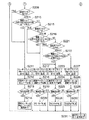
図1は本発明の実施形態に係るシート後処理装置と画像形成装置とからなるシステムの全体構成を示す図である。同図において、このシステムはシート後処理装置100と画像形成装置500とからなる。シート後処理装置100は、入口搬送路A、上搬送路B、排紙搬送路C、スティプル搬送路D、スティプル処理トレイE、中綴じ処理トレイF、及びシフトトレイ排紙部Gを含み、画像形成装置500で画像形成されたシートに対して所定の処理を施し、あるいは、何も処理を施さないで排紙トレイ(以下、積載トレイと称する)10あるいはプルーフトレイB1に排紙する。スティプル搬送路Dはスティプル処理トレイEにシートを搬送するための搬送路で、プレスタック搬送路を備え、1枚あるいは複数枚のシートをスティプル処理トレイEに搬送する。スティプル処理トレイEでは、1ジョブ分のシート束を整合し、中綴じ処理トレイE側に搬送し、あるいは整合されたシート束に端綴じスティプラE1により端綴じ処理を行った後、排紙搬送路Cから積載トレイ10に排紙する。
FIG. 1 is a diagram showing an overall configuration of a system including a sheet post-processing apparatus and an image forming apparatus according to an embodiment of the present invention. In this figure, this system includes a
中綴じ処理トレイE側に搬送されたシート束は、中綴じ処理トレイEで再度整合され、中綴じスティプラF1によってシート束の中央部で綴じ処理される。その後、シート束の綴じ部分が折りプレートの先端に対応する高さまで押し上げられ、中折り部F2で中折りされ、排紙される。 The sheet bundle conveyed to the saddle stitching processing tray E side is aligned again in the saddle stitching processing tray E, and is bound by the center part of the sheet bundle by the saddle stitching stapler F1. Thereafter, the binding portion of the sheet bundle is pushed up to a height corresponding to the front end of the folding plate, folded in the middle folding portion F2, and discharged.
なお、同図において、シートを搬送するためのフィード機構、スティプル機構、中綴じ中折り機構自体は、本発明の特徴ではなく、また公知であるから、詳細な説明は省略する。 In the figure, a feed mechanism for conveying a sheet, a staple mechanism, and a saddle stitching / folding mechanism itself are not features of the present invention and are well known, and thus detailed description thereof is omitted.
前述のようにシート後処理装置100は、画像形成装置500の側部に取り付けられており、画像形成装置500から出力されたシート1は、受入口2aからシート後処理装置100に入り、入口センサS1により検知され、搬送部材であるシートフィーダ4,5,6によって搬送される。次に、分岐爪2e及び2fの回動とシートフィーダ7により排紙搬送路Cに導かれ、シートフィーダ8及び9によって搬送後、積載トレイ10に積載される。なお、分岐爪2eと2fの切り換えは図示していないDCソレノイドあるいは、ステッピングモータで行う。また、シートに対してパンチ処理が必要な場合には、パンチユニット11で1枚ずつパンチ処理が実行される。その際、パンチユニット11を通るシートの先端がセンサS2によって検知される。
As described above, the
積載トレイ10は昇降可能であり、シート排出時には積載トレイ10が所定の位置に待機するように昇降制御される。図2は積載トレイ10の昇降機構Hを示す斜視図である。同図において、積載トレイ10は駆動軸21をトレイ昇降モータ168及びウォームギア25を含む駆動ユニットにより回転駆動することにより昇降する。駆動軸21と従動軸22との間にはタイミングプーリを介してタイミングベルト23がテンションをもって掛けられている。このタイミングベルト23に積載トレイ10を支持する側板24が固定されており、かかる構成によって積載トレイ10を含むユニットが昇降可能に吊り下げられている。なお、トレイ昇降モータ168としては、ブラシレスモータが使用される。ここではブラシレスモータの形式は問わないが、積載トレイ10の最大積載量に対応できる能力を備えているものでなければならないことは言うまでもない。
The
積載トレイ10を上下方向に移動させる前記駆動ユニットでは、駆動源としての正逆転可能なトレイ昇降モータ168で発生した動力がウォームギア25を介して駆動軸21に固定されたギア列の最終ギアに伝達されるようになっている。途中ウォームギア25を介しているため、積載トレイ10を一定位置に保持することが可能であり、機構上、積載トレイ10の不意の落下事故等を防止することができる。
In the drive unit that moves the
積載トレイ10の側板24には、遮蔽板24aが一体に形成されており、下方には積載トレイ10の位置を検出する第1ないし第4の位置検知センサ334,335,336,337が配置され、遮蔽板24aによって位置検知センサ334,335,336,337がオン・オフされる。なお、第1ないし第4の位置検知センサ334,335,336,337は、最上位の第1の位置検知センサ334から下に順に配置されている。
A
このシート後処理装置100の最下流部に位置するシフトトレイ排紙部Gは、シフト排紙ローラ2と、図示しない戻しコロと、紙面検知センサ330と、積載トレイ10と、図示しないシフト機構と、シフトトレイ昇降機構Hとにより構成される。
The shift tray paper discharge section G located at the most downstream portion of the sheet
図2において、符号13はシフト排紙ローラ6から排出されたシートと接して前記シートの後端をエンドフェンス32に突き当てて揃えるためのスポンジ製の戻しコロを示す。この戻しコロ13は、シフト排紙ローラ6の回転力で回転するようになっている。戻しコロ13の近傍にはトレイ上昇リミットスイッチ333が設けられており、シフトトレイ202が上昇して戻しコロ13を押し上げると、前記トレイ上昇リミットスイッチ333がオンしてトレイ昇降モータ168が停止する。これによりシフトトレイ202のオーバーランが防止される。また、戻しコロ13の近傍には、積載トレイ10上に排紙されたシートもしくはシート束の紙面位置を検知する紙面位置検知手段としての紙面検知センサ330が設けられている。
In FIG. 2,
紙面検知センサ330は、紙面検知レバー30と、紙面検知センサ(スティプル用)330aと紙面検知センサ(ノンスティプル用)330bとから構成されている。紙面検知レバー30は、レバーの軸部を中心に回動可能に設けられ、積載トレイ10に積載されたシートの後端上面に接触する接触部30aと扇形の遮蔽部30bとを備えている。上方に位置する紙面検知センサ(スティプル用)330aは主にスティプル排紙制御に用いられ、紙面検知センサ(ノンスティプル用)330bは主にシフト排紙制御に用いられる。
The paper
本実施形態では、紙面検知センサ(スティプル用)330a及び紙面検知センサ(ノンスティプル用)330bは、遮蔽部30bによって遮られたときにオンするようになっている。したがって、積載トレイ202が上昇して紙面検知レバー30の接触部30aが上方に回動すると、紙面検知センサ(スティプル用)330aがオフし、さらに回動すると紙面検知センサ(ノンスティプル用)330bがオンする。シートの積載量が所定の高さに達したことが紙面検知センサ(スティプル用)330aと紙面検知センサ(ノンスティプル用)330bによって検知されると、シフトトレイ202はトレイ昇降モータ168の駆動により所定量下降する。これにより、積載トレイ10の紙面位置は略一定に保たれる。
In the present embodiment, the paper surface detection sensor (for stipple) 330a and the paper surface detection sensor (for non-stipple) 330b are turned on when blocked by the shielding portion 30b. Accordingly, when the stacking tray 202 is raised and the
図3はシート後処理装置100を中心としたシステムの制御構成を示すブロック図である。シート後処理装置100の制御回路350は、CPU360とI/O370を備え、CPU360は画像形成装置500とコマンドやデータの送受信を行う。積載トレイ10を上昇させる際、CPU360はモータドライバ168aにON信号、CW/CCW信号、パルスを発行する。このパルスの周波数はトレイ昇降モータ168の回転速度を決定する。積載トレイ10が上昇する際にCPU360は位置検出センサ334,335,336,337の値を読み込み、積載トレイ10の位置を認識する。CPU360は認識した位置に応じた速度でトレイ昇降モータ168を駆動させるべく、パルス周波数を変更し、モータドライバ168aに発行する。
FIG. 3 is a block diagram showing a control configuration of the system centering on the sheet
CPU360は、タイマ部361、記憶部362を備えるとともに、DCソレノイドのドライバ、DCモータのモータドライバ、ステッピングモータのモータドライバに制御信号を送信し、センサのインターフェースから検知信号を受信し、また、PWMジェネレータ、I/O370等と相互に送受信を行う。また、CPU360は図示しないROM及びRAMを備え、ROMに格納されたプログラムコードをRAMに展開し、当該RAMをワークエリアとして使用しながら前記プログラムコードで定義された制御を実行する。なお、プログラム自体は、制御回路に搭載されているCPUを含むコンピュータが記録媒体から読み取り、あるいはネットワークからダウンロードしてコンピュータに取り込まれる。
The
以下、本実施形態における積載トレイ10の移動制御を実施例毎に説明する。なお、各実施例について、共通の構成要素には同一の参照符号を付し、重複する説明は省略する。
Hereinafter, the movement control of the stacking
図4は、積載トレイの位置に応じてトレイ昇降モータ168の移動速度を制御する実施例1の制御手順を示すフローチャートである。このフローチャートでは、前記第1ないし第4の位置検知センサ334,335,336,337で検知した積載トレイ10の位置に応じて前記駆動ユニットによる積載トレイ10の移動速度を制御する制御手順を示している。図ではセンサをSNと表記している。
FIG. 4 is a flowchart showing a control procedure of the first embodiment for controlling the moving speed of the tray lifting / lowering
同図において、CPU360はシートを積載する積載トレイ10を上昇させるべく、モータドライバ168aにON信号、CW/CCW信号、周波数f0のパルスを発行する(ステップS101)。トレイ昇降モータ168はV0の速度で回転し、積載トレイ10は上昇する(ステップS102)。次に積載トレイ10が所定の待機位置まで上昇したかを判定する(ステップS103)。所定位置まで上昇した場合は、昇降モータ168を停止させ(ステップS117)、所定位置に位置させる。この所定位置は、紙面検知センサ330によって紙面もしくは積載トレイ10の上面が検知された位置であり、前述のようにモードに応じて若干相違する。
In the figure, the
一方、所定位置まで達していない場合、CPU360は第1ないし第4の位置検知センサ334,335,336,337の値を読み込み(ステップS104)、積載トレイ10の位置を認識する(ステップS105)。積載トレイ10の高さを最下位の第4の位置検知センサ337のセンサ位置、下から2段目の第3の位置検知センサ336のセンサ位置、下から3段目の第2の位置検知センサ335のセンサ位置、及び最上位の第1の位置検知センサ334のセンサ位置を基準とし、検出した積載トレイ10の位置が第4の位置検知センサ337より以下であれば(ステップS106−YES)、モータドライバ168aへのパルスをf1に設定し(ステップS107)、トレイ昇降モータ168を速度V1で回転させ(ステップS108)、ステップS103に戻る。
On the other hand, if the predetermined position has not been reached, the
積載トレイ10の位置が第4の位置検知センサ337と第3の位置検知センサ336の間であれば(ステップS109−YES)、モータドライバ168aへのパルスをf2に設定し(ステップS110)、トレイ昇降モータ168を速度V2で回転させ(ステップS111)、ステップS103に戻る。
If the position of the stacking
積載トレイ10の位置が第3の位置検知センサ336と第2の位置検知センサ335の間であれば(ステップS112−YES)、モータドライバ168aへのパルスをf3に設定し(ステップS113)、トレイ昇降モータ168を速度V3で回転させ(ステップS114)、ステップS103に戻る。
If the position of the stacking
積載トレイ10の位置が第2の位置検知センサ335より高ければ(ステップS112−NO)、モータドライバ168aへのパルスをf4に設定し(ステップS115)、トレイ昇降モータ168を速度V4で回転させ(ステップS116)、ステップS103に戻る。なお、第1の位置検知センサ334は上端検知センサとして、また、第4の位置検知センサ337は下端検知センサとして機能している。
If the position of the stacking
すなわち、CPU360は、積載トレイ10の位置が第4の位置検知センサ337以下であるとき、第3および第4の位置検知センサ336,337の間にあるとき、第2および第3の位置検知センサ335,336の間にあるとき(ステップS106,S109,S112)、それぞれの位置に対応したパルス周波数f1,f2,f3,f4を発行し(ステップS107,S110,S113,S115)、トレイ昇降モータ168はV1,V2,V3,V4の速度でそれぞれ回転し(ステップS108,S111,S114,S116)、所定位置まで上昇したか否かの判定(ステップS103)に戻る。そして、所定位置に達するまで前記ステップを繰り返す。
That is, when the position of the stacking
本制御手順における前記トレイ昇降モータ168の速度V0,V1,V2,V3,V4は、駆動源の負荷に対し、適正な回転速度で前記トレイ昇降モータ168を回転させるためにも
V0≦V1≦V2≦V3≦V4
の関係に設定されていることが好ましい。すなわち、積載トレイ10の位置が高い方がより高速で移動するように設定されている。これは前記位置が高い方が低い場合に比べてシートの積載量が少ないと考えられるからである。例えば、積載トレイ10の位置が低いときに少しだけシートが抜かれた場合、シート積載量が多いにも拘わらず、トレイ昇降モータ168の駆動速度を上げると、過負荷になる場合があるからである。
The speeds V0, V1, V2, V3, and V4 of the
It is preferable that the relationship is set. That is, it is set so that the higher the position of the stacking
ただし積載トレイが上昇し、所定位置で停止する際の停止位置精度を向上させることを考慮し、第4の位置検知センサ337を越えた時点で速度を減速させ、
V4≦V0≦V1≦V2≦V3
としても良い。
However, in consideration of improving the stop position accuracy when the stacking tray rises and stops at a predetermined position, the speed is reduced when the fourth
V4 ≦ V0 ≦ V1 ≦ V2 ≦ V3
It is also good.
図5は所定時間以上連続して積載トレイ10を駆動する際に実行される実施例2のモータ制御の制御手順を示すフローチャートである。この例は、所定時間内に上昇動作を完了している場合には、実施例1の制御を実行しないようにしたものである。
FIG. 5 is a flowchart showing a control procedure of motor control according to the second embodiment which is executed when the stacking
図5において、CPU360は積載トレイ10を上昇させるべく、モータドライバ168aにON信号、CW/CCW信号、周波数f0のパルスを発行する(ステップS101)。トレイ昇降モータ168はV0の速度で回転し、積載トレイ10は上昇する(ステップS101a)。CPU360はタイマ部361で上昇時間の測定を開始し(ステップS101b)、次いで、積載トレイ10が所定の待機位置まで上昇したか否かを判定する(ステップS101c)。所定位置まで上昇していれば(ステップS101c−上昇した)、トレイ昇降モータ168を停止させる(ステップS117)。所定位置まで達していない場合には(ステップS101c−上昇していない)、トレイ積載トレイ168の上昇時間が所定時間T1を経過したか否かを判定する(ステップS101d)。経過していない場合(ステップS101d−NO)、ステップS101cの積載トレイ10が所定位置まで上昇したかどうかの判定処理に戻り、所定時間経過する前に上昇した場合には、積載トレイ10が紙面検知センサ330によって検知された所定の待機位置に位置していることになるので、ステップS104以降の処理に移行することなく昇降モータを停止する(ステップS117)。
In FIG. 5, the
ステップS101dで所定時間T1を経過したら、言い換えれば、所定時間T1を経過する前に所定の待機位置まで上昇していなければ、実施例1のステップS104からステップS116までの処理を実行し、ステップS101cで所定の待機位置に達したかどうかを判定する。そして、所定の待機位置に達するまで、ステップS101d以降の処理を繰り返し、所定の待機位置に達した時点でトレイ昇降モータ168を停止する(ステップS117)
なお、ステップS101dの所定時間T1は、任意に設定することができるが、例えば、積載トレイ10がシート排紙時の最大上昇量を移動するときの時間に設定する。この時間はトレイ昇降モータ168の下方位置から前記所定の待機位置までの速度及び加速度を含む駆動特性によって変化するので、対象となる装置によって適宜設定される。
When the predetermined time T1 has elapsed in step S101d, in other words, if the position has not risen to the predetermined standby position before the predetermined time T1 has elapsed, the processing from step S104 to step S116 of the first embodiment is executed, and step S101c is performed. It is determined whether or not a predetermined standby position has been reached. Then, the processes after step S101d are repeated until the predetermined standby position is reached, and the
Note that the predetermined time T1 in step S101d can be arbitrarily set. For example, the predetermined time T1 is set to a time when the stacking
図6はトレイ昇降モータ168の速度設定後、移動時に過負荷状態を検知した際に実行される実施例3のモータ制御の制御手順を示すフローチャートで、図6A及び図6Bで1つのフローチャートを構成している。この実施例3では、CPU360はまず、記憶部362内に配置された過負荷検知フラグOVLF2〜4をFALSEにセットする(ステップS201)。過負荷検知フラグOVLF2〜4は、第1ないし第4の位置検知センサ334,335,336,337によって検知された積載トレイ10の位置と対応付けられている。CPU360は積載トレイ10を上昇させるべく、モータドライバ168aにON信号、CW/CCW信号、周波数f0のパルスを発行する(ステップS202)。この指示によってトレイ昇降モータ168はV0の速度で回転し、積載トレイ10は上昇する(ステップS203)。
FIG. 6 is a flowchart showing a control procedure of motor control of the third embodiment that is executed when an overload state is detected during movement after the speed of the tray lifting / lowering
次いで、CPU360はタイマ部361で上昇時間の測定を開始し(ステップS204)、積載トレイ10が所定の待機位置まで上昇したか否かを判定する(ステップS205)。所定位置まで上昇している場合は(ステップS205−上昇した)、上昇の必要がないのでトレイ昇降モータ168を停止させる(ステップS231)。所定位置まで達していない場合は(ステップS205−上昇していない)、積載トレイ10の上昇時間が所定時間T1を越えたか否かを判断する(ステップS206)。所定時間T1は実施例2で述べた通りである。ステップS206のチェックで所定時間T1を超えていない場合は(ステップS205−NO)、ステップS205に戻り、積載トレイ10が所定位置まで上昇したかどうかの処理以降の手順を繰り返す。一方、前記所定時間T1を超えている場合(ステップS205−YES)、CPU360は第1ないし第4の位置検知センサ334,335,336,337の値を読み込み(ステップS207)、積載トレイ10の位置を認識する(ステップS208)。
Next, the
位置認識後、過負荷検知フラグOVLF2の状態をチェックし(ステップS209)、過負荷検知フラグOVLF2がTRUEの場合は、積載トレイ10位置の判定を行わず、モータドライバ168aへのパルスをf1に設定し(ステップS211)、トレイ昇降モータ168を速度V1で回転させる(ステップS212)。一方、過負荷フラグOVLF2がFALSEであれば、積載トレイ10の位置を判定する(ステップS210)。そして、積載トレイ10の位置が第4の位置検知センサ337以下であれば(ステップS210−YES)、ステップS211以降の処理を実行し、以下でなければ(ステップS210−NO)過負荷フラグOVLF3の状態をチェックする(ステップS215)。
After the position recognition, the state of the overload detection flag OVLF2 is checked (step S209). If the overload detection flag OVLF2 is TRUE, the position of the stacking
ステップS215のチェックで過負荷フラグOVLF3がTRUEであれば、積載トレイ10位置の判定を行わず、モータドライバ168aへのパルスをf2に設定し(ステップS217)、トレイ昇降モータ168を速度V2で回転させる(ステップS218)。一方、過負荷フラグOVLF3がFALSEであれば、積載トレイ10の位置を判定する(ステップS216)。そして、積載トレイ10の位置が第3及び第4の位置検知センサ336,337の間であれば(ステップS216−YES)、ステップS217以降の処理を実行し、第3及び第4の位置検知センサ336,337の間でなければ(ステップS216−NO)、過負荷フラグOVLF4の状態をチェックする(ステップS221)。
If the overload flag OVLF3 is TRUE in the check in step S215, the
ステップS221のチェックで過負荷フラグOVLF4がTRUEであれば、積載トレイ10位置の判定を行わず、モータドライバ168aへのパルスをf3に設定し(ステップS223)、トレイ昇降モータ168を速度V3で回転させる(ステップS224)。一方、過負荷フラグOVLF4がFALSEであれば、積載トレイ10の位置を判定する(ステップS222)。そして、積載トレイ10の位置が第2及び第3の位置検知センサ335,336の間であれば(ステップS222−YES)、ステップS223以降の処理を実行し、第2及び第3の位置検知センサ335,336の間でなければ(ステップS222−NO)、モータドライバ168aへのパルスをf4に設定し(ステップS227)、トレイ昇降モータ168を速度V4で回転させる(ステップS228)。
If the overload flag OVLF4 is TRUE in the check in step S221, the position of the stacking
なお、過負荷検知フラグOVLF2〜4のセットは、トレイ昇降モータ168の各速度を設定し、トレイ昇降モータ168を回転させた後(ステップS212,218,224,228)、モータドライバ168aから出力される過負荷状態信号を読み込み(ステップS213,S219,S225,S229)、そして、ステップS213で過負荷状態であれば、言い換えれば、トレイ昇降モータ168の速度がV1に設定されている状態で過負荷を検知した場合は、システムに不具合が発生したもの判断し、昇降モータを停止し、エラー終了とする(ステップS214)。ステップS219,S225,S229で過負荷状態であれば、それぞれ過負荷フラグOVLF2,3,4をTRUEにセットして(ステップS220,S226,S230)ステップS205の処理に戻る。
The overload detection flags OVLF2 to 4 are set from the
ステップ214のエラー終了では、エラーが発行され、画像形成装置500の図示しない表示パネルに積載トレイ10の駆動不能で動作が停止した旨のエラー表示が行われる。
At the end of the error in step 214, an error is issued, and an error display is displayed on the display panel (not shown) of the
なお、ステップS213,S219,S225,S229における過負荷検知では、本実施例ではモータを駆動するための駆動ICからなるモータドライバ168aの機能を使用しているが、この機能を使用せずに、別途電流検知回路等で検知しても良い。
In addition, in the overload detection in steps S213, S219, S225, and S229, the function of the
なお、本実施形態では、積載トレイ10の位置を検知するために第1ないし第4の位置検知センサ334,335,336,337を使用しているが、この他に、例えば従動軸22と同軸に円板状のエンコーダを設け、このエンコーダの回転を光センサによって読み取り、位置検出を行うように構成することもできる。また、タイミングベルト23の背面側に回転方向を直交する線状のマークを等間隔で付し、このマークを光センサで読み取るようにしてエンコーダを構成し、位置検出を行うこともできる。
In the present embodiment, the first to fourth
また、ステップS219で過負荷状態であれば、ステップS220で過負荷フラグOVLF2をTRUEにセットし、ステップS205に戻って以降の処理を繰り返すことになるが、ステップS209で過負荷フラグOVLF2がTRUEとなるので、ステップS211でモータドライバ168aへのパルスをf1に設定し、ステップS212でトレイ昇降モータ168をV1の速度に落として積載トレイを上昇させることになる。このようにトレイ昇降モータ168はステップS225,S229で過負荷状態を検知したときも同様にして過負荷フラグOVLFをセットし、このセットされた過負荷フラグOVLFに基づいてトレイ昇降モータ168の減速が行われる。
If it is an overload state in step S219, the overload flag OVLF2 is set to TRUE in step S220, and the process returns to step S205 to repeat the subsequent processing. However, in step S209, the overload flag OVLF2 is set to TRUE. Therefore, in step S211, the pulse to the
以上のように、本実施形態によれば、
1)第1ないし第4の位置検知センサ334,335,336,337で検知した積載トレイ10の位置に応じてトレイ駆動モータ168の速度を制御することにより、駆動負荷に応じた積載トレイの駆動速度の制御を行うことができるので、積載トレイ10の駆動機構および装置の小型化、低コスト化を図ることが可能になり、また、騒音を低減させることができる。
2)トレイ駆動モータ168の速度制御は、積載トレイ10の上昇時の駆動負荷が大きいときのみ実行するので、制御を簡略化することができる。
3)積載トレイ10の位置が高い場合の方が低い場合よりも上昇速度を速く設定し、適正な駆動負荷以下での移動速度を大きく設定したので、積載トレイ10の所定の待機位置への移動時間の短縮化を図ることができる。
4)前記駆動手段の速度制御は、所定時間以上連続して前記シート積載手段を駆動する際に行うことを特徴とすることで、通常のシート排出時のトレイ昇降動作時には制御を行わないため、シート排出時のスタック性を維持したまま、イニシャル時やシート積載手段からシートが大量に除去されたとき等に積載トレイを所定の待機位置に移動させる時間の短縮化が可能になる
5)トレイ昇降モータ168の速度制御(速度設定)後に前記トレイ昇降モータ168の過負荷状態を検知した場合は、当該トレイ昇降モータ168の駆動速度を下げるので、常に駆動源の適正な駆動負荷以下で駆動することができる。
6)積載トレイ10が第4の位置検知センサより下側の領域に位置し、その領域に対応した設定速度V1で上昇しているときに過負荷状態を検知したときには、トレイ昇降モータ168を停止させ、エラー通知を行うので、最大負荷以上の駆動や、装置の不具合状態での駆動を避けることが可能となり、これにより安全性の向上を図ることができる。
7)積載トレイ10の高さ位置が第1の位置検知センサ334による検知以上になったとき、トレイ昇降モータ168の速度V4を例えば積載トレイ10の初期速度V0より低速とすることにより、上昇時に積載トレイ10が加速したか否かにかかわらず、積載トレイの停止位置精度の向上を図ることができる。
8)トレイ駆動モータ168がブラシレスモータからなるので、長期にわたって信頼性の高い装置を提供することができる。
などの効果を奏する。
As described above, according to the present embodiment,
1) Driving the stacking tray according to the driving load by controlling the speed of the
2) Since the speed control of the
3) Since the rising speed is set faster when the position of the stacking
4) The speed control of the driving means is performed when the sheet stacking means is driven continuously for a predetermined time or longer, and control is not performed during the tray lifting operation during normal sheet discharge. It is possible to shorten the time for moving the stacking tray to a predetermined standby position when initializing or when a large amount of sheets are removed from the sheet stacking means while maintaining the stackability when discharging the sheet. When an overload state of the tray lifting / lowering
6) When an overload condition is detected when the stacking
7) When the height position of the stacking
8) Since the
There are effects such as.
なお、本発明は、本実施形態に限定されるものではなく、特許請求の範囲に記載された技術思想に含まれる全ての技術的事項に及ぶことは言うまでもない。 Needless to say, the present invention is not limited to this embodiment, but covers all technical matters included in the technical idea described in the claims.
10 積載トレイ
21 駆動軸
22 従動軸
23 タイミングベルト
24 側板
25 ウォームギア
100 シート後処理装置
168 トレイ昇降モータ
168a モータドライバ
334 第1の位置検知センサ
335 第2の位置検知センサ
336 第3の位置検知センサ
337 第4の位置検知センサ
350 制御回路
360 CPU
500 画像形成装置
DESCRIPTION OF
500 Image forming apparatus
Claims (9)
該シート積載手段を昇降させる昇降手段と、
前記昇降手段を駆動する駆動手段と、
前記駆動手段の駆動速度を制御する制御手段と、
前記シート積載手段の上下方向の位置を検知する位置検知手段と、
を有するシート積載装置において、
前記制御手段は、
前記駆動手段により予め設定した時間以上連続して前記シート積載装置を駆動する場合に、前記駆動手段が駆動開始した後、所定時間より短い間は前記駆動速度を定速に設定して制御し、
前記シート積載手段の上昇時であって前記所定時間以降は前記位置検知手段によって検知した上下方向の位置をH1,H2、それぞれの位置H1,H2における前記駆動速度をV1,V2とし、前記位置が
H1<H2
のときには、前記駆動速度を
V1≦V2
として制御し、
前記駆動速度を定速に設定した後、前記駆動手段の過負荷状態を検知した場合は、前記駆動速度を前記設定された速度よりもさらに低速に設定すること
を特徴とするシート積載装置。 A sheet stacking means for stacking sheets and moving up and down;
Elevating means for elevating the sheet stacking means;
Driving means for driving the elevating means;
Control means for controlling the drive speed of the drive means;
Position detecting means for detecting the vertical position of the sheet stacking means;
In a sheet stacking apparatus having
The control means includes
When driving the sheet stacking device continuously for a preset time or longer by the driving means, after the driving means starts driving, the driving speed is set to a constant speed and controlled for a period shorter than a predetermined time,
When the sheet stacking means is raised and after the predetermined time, the vertical positions detected by the position detecting means are H1 and H2, and the driving speeds at the respective positions H1 and H2 are V1 and V2, respectively.
H1 <H2
When the drive speed is
V1 ≦ V2
And to control,
After setting the driving speed to a constant speed, if an overload state of the driving unit is detected, the driving speed is set to be lower than the set speed .
前記位置検出手段によって検出される前記シート積載手段の上下方向の位置に応じて複数の領域を設定し、前記シート積載手段が予め設定された最下位の領域を予め設定された速度で上昇している際に、前記駆動手段の過負荷状態を検知したとき、前記駆動手段の動作を停止することを特徴とするシート積載装置。 The sheet stacking apparatus according to claim 1,
A plurality of areas are set according to the vertical position of the sheet stacking means detected by the position detecting means, and the sheet stacking means raises a preset lowest area at a preset speed. The sheet stacking apparatus is characterized in that when the overload state of the driving unit is detected, the operation of the driving unit is stopped .
前記制御手段は、前記駆動手段の動作を停止したときには、エラー通知を行うことを特徴とするシート積載装置。 The sheet stacking apparatus according to claim 2 ,
The sheet stacking apparatus according to claim 1, wherein the control unit issues an error notification when the operation of the driving unit is stopped .
前記制御手段は、前記シート積載手段が予め設定された最上位の領域に上昇したとき、前記駆動速度を予め設定された複数の速度のうち最小の速度とすることを特徴とするシート積載装置。 The sheet stacking apparatus according to claim 2 ,
The control unit is configured to set the driving speed to a minimum speed among a plurality of preset speeds when the sheet stacking means rises to a preset uppermost area .
前記位置検知手段が前記シート積載手段の移動位置または前記昇降手段の回転位置を検知する光検知手段を備えていることを特徴とするシート積載装置。 In the sheet stacking apparatus according to any one of claims 1 to 4,
The sheet stacking apparatus, wherein the position detecting unit includes a light detecting unit that detects a moving position of the sheet stacking unit or a rotation position of the lifting unit .
前記駆動手段がブラシレスモータからなることを特徴とするシート積載装置。 The sheet stacking apparatus according to any one of claims 1 to 5 ,
The sheet stacking apparatus according to claim 1, wherein the driving means is a brushless motor .
Priority Applications (2)
| Application Number | Priority Date | Filing Date | Title |
|---|---|---|---|
| JP2008130822A JP5146103B2 (en) | 2008-05-19 | 2008-05-19 | Sheet stacking apparatus, sheet processing apparatus, and image forming apparatus |
| US12/453,200 US8002274B2 (en) | 2008-05-19 | 2009-05-01 | Sheet stacking device, drive control method, and computer program product |
Applications Claiming Priority (1)
| Application Number | Priority Date | Filing Date | Title |
|---|---|---|---|
| JP2008130822A JP5146103B2 (en) | 2008-05-19 | 2008-05-19 | Sheet stacking apparatus, sheet processing apparatus, and image forming apparatus |
Publications (2)
| Publication Number | Publication Date |
|---|---|
| JP2009280290A JP2009280290A (en) | 2009-12-03 |
| JP5146103B2 true JP5146103B2 (en) | 2013-02-20 |
Family
ID=41315428
Family Applications (1)
| Application Number | Title | Priority Date | Filing Date |
|---|---|---|---|
| JP2008130822A Expired - Fee Related JP5146103B2 (en) | 2008-05-19 | 2008-05-19 | Sheet stacking apparatus, sheet processing apparatus, and image forming apparatus |
Country Status (2)
| Country | Link |
|---|---|
| US (1) | US8002274B2 (en) |
| JP (1) | JP5146103B2 (en) |
Families Citing this family (13)
| Publication number | Priority date | Publication date | Assignee | Title |
|---|---|---|---|---|
| JP5332694B2 (en) * | 2009-02-16 | 2013-11-06 | 株式会社リコー | Sheet processing system, sheet supply control method, and sheet supply control program |
| JP2011236015A (en) | 2010-05-11 | 2011-11-24 | Ricoh Co Ltd | Image forming system, and enclosing method into envelope |
| JP5378438B2 (en) * | 2011-03-23 | 2013-12-25 | 京セラドキュメントソリューションズ株式会社 | Image forming apparatus |
| JP5733006B2 (en) | 2011-05-02 | 2015-06-10 | 株式会社リコー | Sheet processing apparatus, image forming system, and sheet acceptance control method |
| JP5844597B2 (en) * | 2011-10-07 | 2016-01-20 | コニカミノルタ株式会社 | Method for moving sheet storage device and lifting tray to initial position |
| JP5938909B2 (en) | 2012-01-11 | 2016-06-22 | 株式会社リコー | Paper transport system, paper transport program, and paper transport method |
| JP5891929B2 (en) * | 2012-04-24 | 2016-03-23 | ブラザー工業株式会社 | Transport device |
| JP5692455B2 (en) * | 2014-09-24 | 2015-04-01 | 株式会社リコー | Sheet processing apparatus and image forming system |
| JP6493289B2 (en) * | 2016-04-26 | 2019-04-03 | 京セラドキュメントソリューションズ株式会社 | Sheet stacking apparatus, sheet post-processing apparatus including the same, and image forming apparatus |
| JP6875210B2 (en) * | 2017-06-20 | 2021-05-19 | 株式会社東芝 | Sheet post-processing device |
| CN108726247A (en) * | 2018-06-27 | 2018-11-02 | 温州欧利特机械设备有限公司 | The collection bracket tray positioning apparatus of die-cutting machine |
| CN113734973A (en) * | 2020-05-28 | 2021-12-03 | 中强光电股份有限公司 | Control system and control method for forklift |
| JP2022037635A (en) | 2020-08-25 | 2022-03-09 | 株式会社リコー | Sheet processing device, image forming apparatus, and image forming system |
Family Cites Families (12)
| Publication number | Priority date | Publication date | Assignee | Title |
|---|---|---|---|---|
| JPH02265825A (en) * | 1989-04-06 | 1990-10-30 | Ricoh Co Ltd | Paper supply tray lift |
| DE4020429C1 (en) * | 1990-06-27 | 1991-11-21 | Heidelberger Druckmaschinen Ag, 6900 Heidelberg, De | |
| DE9202352U1 (en) * | 1992-02-24 | 1992-08-06 | Heidelberger Druckmasch Ag | |
| JPH10181980A (en) * | 1996-12-25 | 1998-07-07 | Ricoh Co Ltd | Loading device for sheet member |
| JPH11130319A (en) * | 1997-10-24 | 1999-05-18 | Ricoh Co Ltd | Sheet after-treatment device |
| US6231045B1 (en) * | 1998-06-12 | 2001-05-15 | Ricoh Company, Ltd. | Finisher for an image forming apparatus |
| JP2000177911A (en) | 1998-12-11 | 2000-06-27 | Ricoh Co Ltd | Sheet loading device |
| US6378860B1 (en) * | 1999-07-21 | 2002-04-30 | Hewlett-Packard Company | Collection tray overload detection and recovery |
| JP2001031313A (en) * | 1999-07-22 | 2001-02-06 | Canon Inc | Sheet material stacking device and image forming device |
| JP2001233532A (en) * | 2000-02-23 | 2001-08-28 | Minolta Co Ltd | Sheet port-treating device |
| JP2005170578A (en) | 2003-12-10 | 2005-06-30 | Konica Minolta Business Technologies Inc | Post-treatment device and image forming device |
| JP2007062921A (en) * | 2005-08-31 | 2007-03-15 | Canon Inc | Sheet stacking device and sheet processing device, and image forming device having the same |
-
2008
- 2008-05-19 JP JP2008130822A patent/JP5146103B2/en not_active Expired - Fee Related
-
2009
- 2009-05-01 US US12/453,200 patent/US8002274B2/en active Active
Also Published As
| Publication number | Publication date |
|---|---|
| JP2009280290A (en) | 2009-12-03 |
| US8002274B2 (en) | 2011-08-23 |
| US20090283961A1 (en) | 2009-11-19 |
Similar Documents
| Publication | Publication Date | Title |
|---|---|---|
| JP5146103B2 (en) | Sheet stacking apparatus, sheet processing apparatus, and image forming apparatus | |
| KR100404558B1 (en) | Sheet post-processing apparatus having offset mounting means | |
| US7591459B2 (en) | Sheet feeding apparatus and image forming apparatus | |
| EP1971123B1 (en) | Image scanning apparatus and image scanner | |
| JP5817759B2 (en) | Paper stacking apparatus, image forming apparatus, paper processing apparatus, image forming system, and paper stacking control method | |
| EP1971122A2 (en) | Image scanning apparatus and image scanner | |
| EP1970336A2 (en) | Image scanning apparatus and image scanner | |
| JP2005303610A (en) | Automatic manuscript feeder and image reader | |
| KR101760361B1 (en) | Sheet stacking apparatus, control method of sheet stacking apparatus, and storage medium | |
| JP2007106539A (en) | Paper feeding device | |
| JP5844597B2 (en) | Method for moving sheet storage device and lifting tray to initial position | |
| JP2003054769A (en) | Capacity control system for paper feeding elevator | |
| US7887045B2 (en) | Method for dynamically lifting elevator platform of media input tray during ongoing media process | |
| JP2010195501A (en) | Sheet loading device, sheet processing device, image forming device, lifting drive control method for sheet loading device, and lifting drive control program | |
| JP2010195502A (en) | Sheet loading device, sheet processing device, image forming device, image forming system, lifting drive control method for sheet loading device, and lifting drive control program | |
| JP4208321B2 (en) | Sheet stacking device | |
| JP3692720B2 (en) | Paper post-processing device | |
| JP2009102096A (en) | Paper sheet post-processing device | |
| JP5494909B2 (en) | Paper stacking apparatus and image forming apparatus | |
| JP2002068561A (en) | Sheet loader and sheet processor | |
| JP2688410B2 (en) | Sorter | |
| JP2023082978A (en) | Sheet stacking device, sheet stacking method and program | |
| JP2004262606A (en) | Sheet feeder and image forming apparatus using the same | |
| JPH10139255A (en) | Post-processing device | |
| JP2013091556A (en) | Sheet stacking device and image forming apparatus |
Legal Events
| Date | Code | Title | Description |
|---|---|---|---|
| A621 | Written request for application examination |
Free format text: JAPANESE INTERMEDIATE CODE: A621 Effective date: 20110112 |
|
| A977 | Report on retrieval |
Free format text: JAPANESE INTERMEDIATE CODE: A971007 Effective date: 20120409 |
|
| A131 | Notification of reasons for refusal |
Free format text: JAPANESE INTERMEDIATE CODE: A131 Effective date: 20120417 |
|
| A521 | Request for written amendment filed |
Free format text: JAPANESE INTERMEDIATE CODE: A523 Effective date: 20120618 |
|
| TRDD | Decision of grant or rejection written | ||
| A01 | Written decision to grant a patent or to grant a registration (utility model) |
Free format text: JAPANESE INTERMEDIATE CODE: A01 Effective date: 20121030 |
|
| A61 | First payment of annual fees (during grant procedure) |
Free format text: JAPANESE INTERMEDIATE CODE: A61 Effective date: 20121112 |
|
| R151 | Written notification of patent or utility model registration |
Ref document number: 5146103 Country of ref document: JP Free format text: JAPANESE INTERMEDIATE CODE: R151 |
|
| FPAY | Renewal fee payment (event date is renewal date of database) |
Free format text: PAYMENT UNTIL: 20151207 Year of fee payment: 3 |
|
| LAPS | Cancellation because of no payment of annual fees |