JP5142000B2 - Sludge scraping device - Google Patents
Sludge scraping device Download PDFInfo
- Publication number
- JP5142000B2 JP5142000B2 JP2001139337A JP2001139337A JP5142000B2 JP 5142000 B2 JP5142000 B2 JP 5142000B2 JP 2001139337 A JP2001139337 A JP 2001139337A JP 2001139337 A JP2001139337 A JP 2001139337A JP 5142000 B2 JP5142000 B2 JP 5142000B2
- Authority
- JP
- Japan
- Prior art keywords
- scraper
- cam
- slider
- sludge
- airframe
- Prior art date
- Legal status (The legal status is an assumption and is not a legal conclusion. Google has not performed a legal analysis and makes no representation as to the accuracy of the status listed.)
- Expired - Fee Related
Links
Images


Description
【0001】
【発明の属する技術分野】
この発明は、汚泥掻寄装置に関する。
【0002】
【従来の技術】
例えば、矩形の沈澱池においては、その長手方向一端池底に汚泥ピットが形成され、同ピットには、池底に沈澱する汚泥を汚泥掻寄装置により掻き寄せて落とし込まれるようになっている。そして、この汚泥掻寄装置には種々のものがあるが、フライト循環駆動方式によるものと転動輪を備えてスクレーパ付機体を進退自在にしたものとが一般的なものとしてある。
後者のものは、処理池の長手方向にガイドレールを敷設し、同ガイドレールに、転動輪付でスクレーパ付の機体を進退自在に構成するのであるが、その場合、スクレーパは、ピットの方向である掻寄方向には垂直に、またその逆方向には汚泥を掻き戻さない水平に姿勢を切り換えるようになっている。これらの切り換えは、ワイヤロープの往復運動により連動してなされるようになっている。
【0003】
【発明が解決しようとする課題】
しかし、これまでは、前記スクレーパの切り換え時に切り換えよりも先に転動輪がガイドレール上で滑ってしまう現象もあったため、その対策をとってきた訳である。ところで、その方法としては、ガイドレール上に凸部を備えてこれに転動輪が一旦係留されるようにしたものなど種々のものがあるが、今一つ有効で簡易なものはない。
この発明はこうした問題を解決するためになされたものであり、より確実で有効なスリップ防止効果が得られるとともにそれが簡単な構造のもとに達成されるようにした汚泥掻寄装置を提供することにある。
【0004】
【課題を解決するための手段】
前記課題を解決するため、請求項1記載の発明は、池底の一端に汚泥ピットを有する沈澱池の池底に敷設されたガイドレール上には、転動輪付きの機体を装備してワイヤロープによりガイドレールに添って進退駆動自在とされるとともに、同機体には、掻寄姿勢と非掻寄姿勢とに切り換え自在なスクレーパとを備える汚泥掻寄装置において、前記機体には、スライド受を介して前後に進退自在な四角筒状の第2スライダが嵌装され、同第2スライダには、角軸状の第1スライダが前後にスライドするように嵌装されてその前後端に前記ワイヤロープがそれぞれ連結されるとともに、同第2スライダは、スクレーパ連動リンクを介して前記スクレーパに連結され、前記第1スライダにおける第2スライダより一定量S離れた前後位置には、ストッパブロックが設けられるとともに、これら前後のストッパブロックを介して第2スライダに平行な1本のカム受が取り付けられ、このカム受の左右両側面には、左右一対のカムが横張出状をなすように設けられ、各カムは、前後に傾斜面を有しその傾斜面間が左右において互いに平行な面となるようにつながれた形とされる一方、前記機体には、前記カムに接触しながら転動するカムローラーを上端に有し下端にはガイドレールに接離自在なブレーキシューを備えたカムレバーが機体の前後方向に軸心を向けた軸を介して回転自在な状態で左右一対配備されるとともに、同カムレバーと機体間には、カムローラーをカムに向けて押し付けるバネが設けられてなることを特徴とする。
【0005】
【発明の実施の形態】
以下、図示した実施形態を参照してこの発明を詳細に説明する。
図5は矩形沈澱池1の全体を示し、同沈澱池1において、図の左右が長手方向で、2は整流壁、3は池底、4は汚泥ピットをそれぞれ示している。そして、池底3上には、図2〜図4に示すように、溝形鋼の左右1対を少し離間させてガイドレール5を敷設してある。両ガイドレール5,5の上面には上蓋6が装備されて汚泥がガイドレール5,5間に入らないようにしてある。
【0006】
8は池上に設置された駆動手段(駆動源、減速機、ドラム等でなる)、9…はシーブ、10はワイヤロープをそれぞれ示し、側面からみるとL字状の軌道に掛け渡され、同ワイヤロープ10の一部は、図3及び図4に示すように、ガイドレール5,5間を通り、その上の一部はガイドレール5,5の上蓋6上を進退駆動自在に通るようにされている。
【0007】
12は転動輪、13は機体であり、機体13は、前部Fと後部R及びその前後間を継ぐ連結パイプ14とでなる。前部Fの前側と後部Rの後側にはスクレーパ15が装備され、図5の実線の状態は掻寄姿勢でそれぞれのスクレーパ25は垂直な状態にありその状態で機体13が前進することにより汚泥がピット4方向に掻き寄せられる。前側のスクレーパ25がピット4上にきたところでワイヤロープ10が図4の右方向に逆駆動され、これにより、前側のスクレーパ25はピット方向に水平に持ち上げられ、後側のスクレーパ25は半ピット方向に水平に持ち上げられるようになっていて、その姿勢が復帰姿勢(非掻寄姿勢)とされて機体は戻される。
【0008】
概要は以上のようであるが、次にその詳細について図1〜図4を用いて詳細に構造説明をする。
前記機体13は、図4にその断面を示すように、H形鋼で幅の大きいものを本体17として用い、その前後及び適所に貫通穴を形成してある。そして、機体13の前端及び後端に各スクレーパ18,19が装備されているとともに、図1に示すように、前部Fの後端と後部Rの前端にブラケット20を介して前記連結パイプ14が連結されている。
【0009】
22は第1軸、23は第2軸で、第1軸22は、前部Fにおいては機体13を通じて左右に長く伸びるもので機体13に固定されている。第2軸23は、機体13の幅よりも少し長い程度の短い軸で、これも機体13に固定されている。
【0010】
後部Rにあっては、第1軸22と第2軸23とは前後に逆の関係になっている。そして、各軸22,23の外周には前記転動輪12…が回転自在に装備されている。この転動輪12についての詳細断面は、図3に示されている。即ち、この実施形態では、小径の筒と大径の筒それに円板とを一体に溶接したものでなり、こうした転動輪12を軸受を介して第2軸23回りに回転自在にしてある。第1軸22の機体13から左右に突き出した部分の外周には軸受を介して回転自在にスクレーパパイプ24が装備され、同スクレーパパイプ24の下側には、スクレーパ25が、また上側には上スクレーパ26が突設されている。上スクレーパ26の特に上端バー26aは、進退時のスクレーパの安定化のため四角などの中実バーが使用され、図1のように掻寄姿勢の時には回転中心より少し前寄りに位置して安定化に寄与し、また、復帰姿勢時にも安定化に寄与するようになっている。
【0011】
28はブラケットで、機体13の前後間両端に装備され、同ブラケット28を介してガイドレール5の溝内に嵌まる浮き上がり防止ローラー29が設けられ、同ローラー29により機体13が上に浮き上がらないようにする。
【0012】
以下機体13の前部Fについて説明するが、後部Rについては同様の符号を付して説明に代える。
前部Fのウエッブ上には、幅間中央線上の前後2か所に取付台31が一体に固定されている。同取付台31上には、それぞれ前後に中心を向けた四角筒状のスライド受32が固定され、両スライド受32,32は同心状をなすとともに、その内部には樹脂ブッシュ33が嵌装されている。
【0013】
これらのスライド受32,32を介して円滑に進退運動するように前後に長く四角な筒状をした第2スライダ34が嵌装されている。第2スライダ34の長手方向中途両側には、図2に示すようにストッパ突起35,35が左右1対突設されており、これらのストッパ突起35は、進退して樹脂ブッシュ33に当たって止まるようになっている。また、同ストッパ突起35にはスクレーパ連動リンク36の後端部が連結される一方、同連動リンク36の前端部は、上スクレーパ26の前側に通した連動軸37に回転自在に連結されている。
【0014】
39は第1スライダで角軸状であり、その前後端にワイヤロープ10の連結部を有して第2スライダ34に樹脂ブッシュ40を介して前後に円滑にスライドするように嵌装されている。同第1スライダ39の前後端には、ストッパブロック41,41がそれぞれ装着され、同ブロック41上にスペーサ42を介して角筒状をしたカム受44が渡架されている。このカム受44の左右両面には図2に示すように前後を斜面にしその間を平行状にしたカム45,45がそれぞれ横張出状をなして取り付けられている。
【0015】
47はカムローラーで、カム45に接触しながら転動するものであり、同カムローラー47は、図4に示すように、軸受48に軸49を介して左右に揺動自在に支持したカムレバー50の上端内側に装備されている。カムレバー50は、バネ51で常時カムローラー47を内向きに押し付けるように付勢する一方、同レバー50の下端にはブレーキシュー52が装着されてガイドレール5の上部に接離自在になっている。尚、図4の左側は非制動時を右側は制動時の状態をそれぞれ便宜上示すものである。また、後部Rにおいては、前部Fと同様の構成になっているが、スクレーパ連動リンク53については、その後端がスクレーパ25に対して連結されている。
【0016】
図1、図2、図3の左側部分は掻寄状態にある様子を示し、ストッパ突起35が図1の前側のスライド受32の樹脂ブッシュ33に当たったところでスクレーパ連動リンク36を介してスクレーパ25が垂直な姿勢とされ掻寄状態になっている。後部Rにあってもストッパ突起35がスライド受32の樹脂ブッシュ33に当たったところで停止し、これにより、スクレーパ連動リンク53を介してスクレーパ25が下回りで前向きに引かれて垂直な掻寄状態になっている。前部F及び後部Rでは、カムローラー47はバネ51の反発でカム45の後側の斜面位置にある。また、前部F及び後部Rの各後端のストッパブロック41もそれぞれ後部のスライダ受32の樹脂ブッシュ33に当たって止まっている。一方、前部F及び後部Rの各前端のストッパブロック41は、第2スライダ34に対してS程前方に離れた状態になっている。
【0017】
この状態でワイヤロープ10が、図1のX方向に継続して引かれスクレーパ25が汚泥ピット4(図5)上にきたところでワイヤロープ10は図1のY方向に引かれる。これにより、転動輪12が転動する前に、後部R及び前部Fの各第1スライダ39が引かれて第2スライダ34内を後方に摺動し、それまでS程あった隙間は次第に小さくなって後部R及び前部Fの各X側のストッパブロック41が第2スライダ34の樹脂ブロック40に当たるようになる。その間、カム受44もY方向に引かれるので、カム45も同様に移動することでカムローラー47を図4の右側図示のように外向きに押し出すようになり、これにより、シュー52がガイドレール5を捉えて機体13の動きを制動ロックする。
【0018】
ワイヤロープ10が、図1のY方向に更に引かれると、今度は第2スライダ34までも同方向にスライドしてゆき、これにより、機体13が制動ロックされた状態のまま、スクレーパ連動リンク36,53を介してスクレーパ25は水平方向に持ち上がるようになる。その持ち上がりは、ストッパブロック41が各後側のスライド受32に当たることで止まる。その間、カム45も図1のY方向に移動しているので、カムローラー47はカム45の平行(平坦)な面に乗り上がり図4の右側図示の状態になったあと、カム45の前側の斜面に落ち込むようになるので、制動はその時点で解除される。
【0019】
更に、Y方向に引かれることで、制動が解除された状態で機体13はY方向に引かれ転動してゆき、図5の右端に復帰する。次に、図1のX方向にワイヤロープ10が引かれることで前記とは逆の運動をする。即ち、復帰時には図1のa個所においてSの隙間ができており、X方向の駆動によりこのSがなくなるまで第1スライダ39が移動したあと第2スライダ34がX方向にスライドしてスクレーパ25が垂直な掻寄姿勢になる。この際にもまず制動が働いてスクレーパ25が垂直になったあと制動が解除される。
【0020】
尚、図6に示すように、スライド受を上下(あるいは左右)の受ローラー56,56とし、それに第2スライダであるパイプ57を進退自在にして構成してもよい。
また、前記実施形態では前部F及び後部Rを連結したロングタイプの汚泥掻寄装置について説明したが、例えば、前部Fのみの汚泥掻寄装置であってもよい。
【0021】
図7ないし図9は他の実施形態を示すもので、図7は、掻寄方向がXで非掻寄方向(復帰方向)がYで前記実施形態とは逆サイドから汚泥掻寄装置を観ている。
【0022】
60はガイドレールで、図8に示すようにH形断面をしたをその溝が側方にくるようにして設置したものであり、同ガイドレール60は、その底面にベース盤61を介して池底面62上に敷設固定され、その位置は、池幅間中央を通るようにして汚泥ピット(図7のX方向端部に形成)上から池後端(図7のY方向端部)までわたるようにして設けられている。このガイドレール60は、上側のウエッブが下側のものより長くなっているが、これに限定されるものではない。
【0023】
ガイドレール60上には、袴座式に機体63が搭載され、同機体63は、左右1対のコの字形チャンネル材である主ボディ64,64を備え、これらをそれぞれ溝が外向きになるようにして左右に離間して配してあるとともに、主ボディ64,64間を、図9の平面図に示すような幅間つなぎ65で連結一体化しさらに補助つなぎ66および前後の端部つなぎ67で連結してある。
【0024】
機体63内には、前後1対の転動輪68が回転自在に軸受で装備されている。
この転動輪68は、前記実施形態で示したドラム状のものでガイドレール60と略同一の幅をもったものになっている。69はサイドローラーで、上からみて4点配置されてガイドレール60の溝内にあってレール側面に外側から接触し蛇行走行せず直線走行し得るようになっている。
【0025】
70は浮き上がり防止ローラーで、上からみて4点配置されてレール60の上側ウエッブに下から当って機体63が浮き上がらずに安定走行するようになっている。前記機体60の主ボディ64前後端には、U字状の切欠71が形成されている。これらの切欠71を介してスクレーパパイプ72が前後1対軸受支持されている。各スクレーパパイプ72には、スクレーパ73が装備されるとともに上部スクレーパ74が設けられている。上部スクレーパ74には、図示しないバランサが設けられてスクレーパ73が軽快に回転し得るようにされている。
【0026】
75は前部固定スクレーパ、76は後部固定スクレーパであり、その他、図示しないが機体63の底面にもガイドレール60上に溜まるであろう汚泥を掻き落とすための固定スクレーパをも配備している。尚、77はガイドローラーで、同ローラー77も走行を安定化させるために装備されることがある。このローラー77は他の実施形態でも装備することがある。
【0027】
また、78はスクレーパストッパで、スクレーパ73を垂直に規定したり水平に規定したりするものであり、上部のストッパ78には、スクレーパパイプ72回りに突設された回転突起79が非掻寄状態になる際にあたるようになっている。尚、80は側部スクレーパで、ガイドレール60内の汚泥を掻き出すものである。
【0028】
82はスタンドで、前後の各幅間つなぎ65に左右1対をなすものとして立設されるとともに、各スタンド82には、上下にガイドローラー83が上下に離間して装備されている。これらガイドローラー83…を介してメインロッド84が前後に進退自在に装備されている。
【0029】
このメインロッド84の前後端部には、池上の駆動源から駆動されて図7のX方向あるいはY方向に牽引駆動されるワイヤーロープ85がジョイント86を介して連結されている。メインロッド84は、長手方向側面に前ストッパ突起87を備えて、前側のスタンド82側に設けたロッドストッパ88に当たるようにされるとともに、同突起87よりも後方に備えた後ストッパ突起89は後部のロッドストッパ88に当たるようにされている。
【0030】
このメインロッド84のストッパ突起87と前側の上部スクレーパ74との間は、前連動リンク90で連結されている。このリンク90は、図9に示すように左右1対をなし、また、メインロッド84の長手方向中間底面を介して固定したブラケット91と後部のスクレーパ73との間は、後連動リンク92で連結されていてこれも左右1対をなすものである。
【0031】
これらの連動リンク90,92は、前後のスクレーパ73を図7の側面からみてそれぞれ前方・後方に上がるようにするために前連動リンク90をスクレーパパイプ72よりも上方に後連動リンク92を同パイプ72よりも下方にそれぞれ連結したものになっているが、例えば、それぞれのリンク90、92をパイプ72よりも上方又は下方に連結して前後のスクレーパ73が同じ方向に持ち上がるようにしてもよい。また、両リンク90,92をなくして、メインロッド84により直接的にスクレーパ73,73を連動させるようにしてもよい。尚、93は車上カバーリングで、スタンド82の前後間に装架したカバー受け94を介して適宜脱着自在に固定されている。
【0032】
図7から図9はピット方向に汚泥を掻き寄せる状態を示しており、この掻寄状態では、メインロッド84がX方向に牽かれて前進端にあり、この際、同メインロッド84は、前ストッパ突起87が前のロッドストッパ88に当たり、前後のスクレーパ73,73が下部のスクレーパストッパ78に当たることでスクレーパ73,73が垂直な掻寄状態に安定にロックされている。この掻寄状態でX方向に機体63が牽かれてゆくことで、池底の汚泥をピットまで掻き寄せてゆく。
【0033】
機体63がピット上にくることで反転制御手段が働き池上の駆動源を逆回転させる。これにより、ワイヤーロープ85は図7のY方向に牽引され、メインロッド84は同方向に牽かれるようになる。その結果、メインロッド84とともに前連動リンク90及び後連動リンク92はそれぞれ後方に牽かれ、前スクレーパ73は前方向に後スクレーパ73は後方にそれぞれ持ち上げられる。これにより、装置は非掻寄状態になるとともにY方向の牽引により機体63は同方向に牽引され復帰のための走行を始める。一方、装置がY方向に走行して後退端までくると、反転制御手段により駆動源が逆回転されることで、ワイヤーロープ85はX方向に牽引される。これにより、メインロッド84はX方向に同行して前後のスクレーパ73,73はそれぞれ垂直な掻寄状態に切り換えられる。尚、同装置においては、前記実施形態の制動ロック装置や後述する制動ロック装置を付属させることがある。
【0034】
尚、同装置における後側のスクレーパ73は、後退する際に後向きに跳ね上がりその後、下周り前向きにスイングするようになっているので、底面域上の沈澱物を前方へ掻き寄せて沈澱物の溜まりをなくすことができる。
【0035】
図10、図11(図10のXI−XI線断面図)、および図12(XII−XII線断面図)は、汚泥掻寄装置に制動ロック装置Rを装備した他の実施形態を示すものである。同実施形態は、一部を除き図7ないし図9に示す実施形態と同様であるので、同様の部分については同一の符号を付して説明に代える。
【0036】
すなわち、同装置におけるメインロッド84の外周には、長手方向に添って長い遅延連動スライダ97が四角筒状のものとして同ロッド84にスライド自在に設けられている一方、メインロッド84の前後端外周には、前後1対の連動ピース98が固定装備され、同ピース98間の寸法は図10に示すように遅延連動スライダ97の長さよりもS分だけ長くなっている。そして、後側の連動ピース98とメインロッド84の長手方向中程底面には図11、図12にも示すような二股形のレール固定腕99がそれぞれ下向きに突設され、これらを介して左右1対をなすカムレール100が取付けられている。
【0037】
カムレール100は、前部底面に下向きに凸状をなすカム部101を備えている。一方機体63側の主ボディ64の各底面には、支点ブラケット102が左右対向状をなして固定して設けられ、同ブラケット102を介して支点軸103が設けられている。この支点軸103を介して支点体104が取り付けられるとともに、同支点体104上には、前後に回転可能なようにスイング体105が設けられている。同スイング体105の上端には、前記カム部101に当たるカムローラー106が取り付けられている。
【0038】
前記支点体104には、図10に示すように側面からみて4点配置をなす制動子107が図11に示すようにレール60の上フランジに上下から近接するように配置されている。そして、主ボディ64の内面とスイング体105との間には、スイング体105を垂直な中立状態に復帰させる復帰バネ108が設けられている。前記制動子107は、耐磨耗性の優れた金属や樹脂などを使用してあるとともに図11に示すように皿ばね109を介して固定されている。
【0039】
ここで、同制動ロック付汚泥掻寄装置の作動を説明すると、図10はピット方向に汚泥を掻き寄せる掻寄状態を示し、この状態では、前後のスクレーパ73,73が共に垂直下がり状態にあり、ワイヤーロープ85のX方向への牽引によりメインロッド84回りの後端の連動ピース98は外筒である遅延連動スライダ97を後方から押し進めるが、各部のストッパにより図示の一定限度で止まっている。
【0040】
この状態で遅延連動スライダ97の前端と前側の連動ピース98との間には一定の遊隙Sが残されている。そして、制動ロック装置においては、カムローラー106がカム部101の後部に外れて位置するとともに復帰バネ108により垂直に戻された状態にあって制動子107…がガイドレール60のフランジから一定に離間した図11の中立状態になっており、そのまま掻寄は進行する。
【0041】
装置がピット上にきて掻寄が終了すると、ワイヤーロープ85は図10のY方向に牽かれ、これにより、まずメインロッド84が牽かれてS程後方へスライドする。その間、カムレール100も後方へシフトし、これにより、カム部101がカムローラー106を後方向きに応動させることにより、復帰バネ108に抗してスイング体105も後方に回転して、制動子107…がレール60のフランジを挟持するようになる。
【0042】
カムローラー106がカム部101の山に乗り上げるとロック状態が完了し、スイング体105は後方に振れたままになるとともに、前側の連動ピース98が遅延連動スライダ97を後方へと連動させるようになる。この連動により、前・後連動リンク90,92を介して前後のスクレーパ73,73が図10の仮想線のように水平方向に持ち上がるようになる。その間、メインロッド84及び遅延連動スライダ97は同調して後方に移動する。
【0043】
そして、スクレーパ73,73が持ち上がる前の段階で、カムローラー106はカム部101の前側の傾斜面にさしかかるようになり、この時点で次第にロックは解除されるようになって、最終的にスクレーパ73,73が持ち上がった時点で完全にロックは外れた状態になる。ロックが外れると、制動ロック装置は復帰バネ108により中立状態になる。この中立状態は掻寄中継続される。
【0044】
装置が復帰して掻寄状態に切り換わる際にも同様のロック→解除の動作をする。これにより、スクレーパ73が先に切り換え動作をしてのち機体63が進退を開始するようになり、スクレーパ73の切り換え前に機体63が進退してしまうおそれがなくなった。尚、この制動ロック装置は、他の実施形態の掻寄装置にも適用することがある。
【0045】
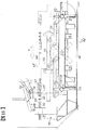
図13および図14(図13のXIII−XIII線断面図)は、他の方式の制動ロック装置を付属した汚泥掻寄装置についての実施形態を示す。
【0046】
同掻寄装置は、前記実施形態と同様の機体112を備え、サイドローラー113及び浮き上がり防止ローラー114を同様に備えている。スクレーパパイプ115も前後に装備してスクレーパ116を装備する。また、スタンド117…及びガイドローラー118…によりメインロッド119が前後に進退自在とされているとともに、同メインロッド119の前後端にはワイヤーロープ120が結合されている。
【0047】
只、この掻寄装置の場合、機体112の長手方向中程のところに回転軸122を横架し、同回転軸122回りに連動レバー123を左右1対のものとして前後に回転自在に支持してある。そして、同連動レバー123の各上端に開けた上部長孔124を介してメインロッド119の連動ピン125にスライド自在に係合させてある。したがって、連動レバー123はメインロッド119に追随して遊びなく応動する関係になっている。
【0048】
一方、スクレーパパイプ115の長手方向の機体112の幅間に対応する位置からは、掻寄状態において前上がり傾斜状をなす応動レバー127が前後同じ姿勢をして突設されている。応動レバー127は前後においてそれぞれ左右1対配備されており、各応動レバー127の前後間には、連結リンク128が結合されている。この連結リンク128は左右1対設けられている。
【0049】
そして、連結リンク128の左右間には応動ピン129が突設されており、このピン129には、前記連動レバー123の中程に開けた下部長孔130が遊隙Cを存して嵌り合っている。そして、前記回転軸122外周には、連動レバー123と共に回転するが図14の矢印のように左右に振れる余裕をもたせたロック板132が嵌め込まれている。このロック板132は、押さえバネ133により常時内方へロック板132を押さえつけるように機能する。尚、ロック板132は、図14のように、レール60の上フランジの端部上にその板厚間が対応するようになっているが、下端に面取り134を有するので、掻寄状態及び非掻寄状態においてガイドレール60のフランジ縁には接触しないものになっている。
尚、連結リンク128上には、バランサ136が重量調節可能に設けられている。このバランサ136については、例えば、上部スクレーパ137に装着して、スクレーパ全体が軽快に作動するようにしてもよい。
【0050】
図13の状態は掻寄状態を示し、同状態において、メインロッド119がX方向に強制的に牽かれ連動レバー123が上ストッパ135にあたることで図示状態を維持する。そして、連結リンク128は、バランサ136などによりスクレーパ116が垂直に規定されることにより図13の状態を維持し、そのことから、応動ピン129と下部長孔130との遊隙Cが確保されるようになる。
【0051】
ワイヤーロープ120がY方向に牽かれて復帰態勢に入ると、メインロッド119がこれに応動するとともに連動レバー123を介してロック板132も応動回転する。しかし、遊隙Cの存在により下部長孔130が応動ピン129をすぐには応動させず、連動レバー123が一定角度回転してのち応動することになる。したがって、その応動に至る間、ロック板132がレール60のフランジを捉え押さえバネ133で押さえられながら次第に強く接当するようになり、機体はロックされた状態になる。そこで、応動ピン129がはじめて下部長孔130に当たって連動レバー123を応動させ、連結リンク128を介してスクレーパ116を跳ね上げるようにする。
【0052】
連動レバー123は図13の仮想線の位置まで回転するが、その手前の段階でロック板132はレール60のフランジから完全に離脱し走行自在な状態に入っている。このロック状態にある範囲は図13に矢印Lで示す。復帰状態から掻寄状態に入る際も上記と同様の作用になる。
【0053】
尚、メインロッド119の凹みUは、進退端においてガイドローラー118に嵌り合う部分で、スクレーパ116は安定化する。凹みUは、前ガイドローラー118に対応する個所にも設けられる。上部スクレーパ137と前部スクレーパ138との間にはつなぎスクレーパ141を配備してもよい。
【0054】
また、ロック板132には、図14に示すように、ウエイト139を付してもよく、この場合、バネ133を省略することもできる。
さらに、図13に示すように、前端の応動レバー127は左右1対設けられているが、その間の前面にスクレーパ板138aを備えて中央前部スクレーパ138を構成してもよい。
【0055】
図15及び図16は他の実施形態を示す。
図13に示す実施形態では、メインロッド119が矢印yの方向にスライドして突き出して復帰するが、その復帰側先端にさらにジョイント141を介してワイヤーロープ120をU字状に掛け付けその掛け付け部分をワイヤ緊締具142により締め付けて固締しておくと、機体112をシーブ側により接近させて復帰できない。すなわち、シーブを通るワイヤーロープ120は、単一状の部分を通すことは問題ないがワイヤ緊締具142のある部分は通すことはできず、したがって、図13のものでは、ワイヤ緊締具142が機体112の後端からシーブ側に大きく離れて位置することになっているため、その分、機体112をシーブ側に一杯迄復帰させるにも限界がある。
【0056】
そこで、図15に示すように、メインロッド119にではなく、同ロッド119に架台145を介して短い中継ロッド146を固設し、同ロッド146にジョイント147を介してワイヤーロープ148をワイヤ緊締具149…で締めつけ固定したものである。このようにすることで、機体112をシーブ150のある側に充分深く復帰させ得るようになった。これにより、復帰端側に溜まり勝ちな汚泥をもピット側に掻き寄せることが可能になった。
【0057】
尚、図15に示すように、ガイドレール60の後端にはシーブブラケット152が設けられ、同ブラケット152を介して位置検出用のアクチュエータ153が支持されているが、このアクチュエータ153を作動させるローラー154を機体112側に支柱155を介して装備してもよい。尚、ローラー154とアクチュエータ153は逆の位置関係になることもある。
【0058】
図17に示す例は、機体158に前記実施形態のように復帰時に前方に跳ね上げる方式でスクレーパ159を装備しておきそのまま降ろして掻寄状態にするように構成すると、汚泥を掻き戻すことになるのを防止するようにしたものである。すなわち、ガイドレール160の後端部を少し高く持ち上げた格好にして段高部161とし、この段高部161に機体158が乗りあがるようにしたもので、これにより、掻き戻しがなくなるとともに逐次掻き寄せることも可能になる。
【0059】
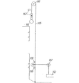
図18に示す例は、機体162が後退あるいは前進してその端部にきたことを検出するための制御手段についてのもので、163は近接スイッチや光電スイッチなどによる検出手段で、その一方を備えウエイト164を備えたワイヤーロープ165を、下端を池底に掛止し上部を滑車166を介して吊り下げたもので、機体162のローラー167に当たる個所の上下2点を受けローラー168で受け止めて仮想線のようにワイヤーロープ165の対応する一部が凹むように作用することで検出手段の一方が持ち上がる結果、検出のための作用をするようにしたものである。
【0060】
前記例では全体がワイヤーロープであったが、図19に示すように、上部はワイヤーロープ170であるが下部は折れ曲がり式リンク171で同リンク171にローラー172が当たるようにしてもよい。
【0061】
また、前記では折れ曲がり式リンクを構成したが、図20に示すように、ガイドローラー175…により昇降自在なロッド176とワイヤーロープ177とを組み合わせて構成してもよい。
【0062】
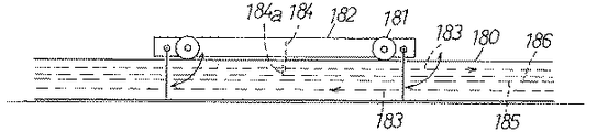
図21及び図22に示す例は、左右1対の溝形ガイドレール180上に転動輪181により走行自在な機体182を装備し、同機体182を図22の矢印のように互いに逆方向に牽引駆動されるチェーン183を装備して上周りのチェーン183に対して機体182から突設したスクレーパ184a付の突出部184に連結したもので、特に、この場合のチェーン183の上回りのものが接触磨耗しないようにガイドレール180間の中段に受け棚185を装架してその上側に樹脂などの滑走受け部186を備えたものである。
【0063】
図23に示す例は、ガイドレール189がH形のもので、その1対間に受け棚190を上方から掛装式に固定しその上側に滑走受け部191を備えたものである。尚、同実施形態では、H形断面をした単胴型機体192になっているが、これに限定されない。
【0064】
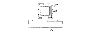
また、図24に示すように、溝型ガイドレール195の間に掛装式に受け棚196を固定し、この受け棚196に滑走受け部197を備えてもよい。尚、同実施形態のように、丸パイプ状で単胴式の機体198にしてもよいがこれに限定されるものではない。さらに同図に示すように、単胴式の機体198にした場合には、例えば、同パイプに長いロッドあるいはパイプを支持軸199として装入し、これを共通軸として転動輪200やスクレーパ201などを装備するようにしてもよい。
尚、前記実施形態における各制動ロック手段は、他の実施形態の汚泥掻寄装置にそれぞれ適用することがある。
【0065】
【発明の効果】
この発明は以上のようであるので、より確実で有効なスリップ防止効果が得られるとともにそれが簡単な構造のもとに達成されるようにした汚泥掻寄装置を提供することができる。
【図面の簡単な説明】
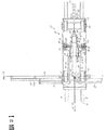
【図1】この発明の一実施形態を示す汚泥掻寄装置の側面図。
【図2】図1の前部の平面図。
【図3】転動輪の構造と取付状態を示す縦断面図。
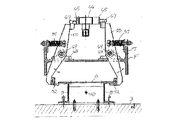
【図4】制動機構の実施形態を示す縦断面図。
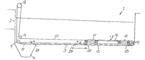
【図5】沈澱池に汚泥掻寄装置を構成したその全体を示す側断面図。
【図6】他の実施形態を示す断面図。
【図7】汚泥掻寄装置の他の実施形態を示す側面図。
【図8】図7の汚泥掻寄装置の正面図。
【図9】図7の汚泥掻寄装置の平面図。
【図10】汚泥掻寄装置の他の実施形態を示す一部切り欠き側面図。
【図11】図10のXI−XI線断面図。
【図12】図10のXII−XII線断面図。
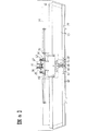
【図13】汚泥掻寄装置の他の実施形態を示す側面図。
【図14】図13のXIV−XIV線断面図。
【図15】汚泥掻寄装置の他の例を示す側断面図。
【図16】図15のXVI−XVI線断面図。
【図17】汚泥掻寄装置の他の実施形態を示す側断面図。
【図18】他の例を示す側断面図。
【図19】他の例を示す側面図。
【図20】他の例を示す側面図。
【図21】汚泥掻寄装置についての他の例を示す縦断正面図。
【図22】図21の側面図。
【図23】他の例を示す縦断正面図。
【図24】他の例を示す縦断正面図。
【符号の説明】
1…沈澱池 3…池底 4…汚泥ピット 5、60…ガイドレール 10、80,120,148…ワイヤーロープ 12、68…転動輪 13、63,112…機体 14…連結パイプ F…前部 R…後部 25、73、114…スクレーパ 45,47,50,51,52、R…制動ロック手段。[0001]
BACKGROUND OF THE INVENTION
The present invention relates to a sludge scraping device.
[0002]
[Prior art]
For example, in a rectangular sedimentation basin, a sludge pit is formed at the bottom of the pond at one end in the longitudinal direction, and sludge settled on the bottom of the pond is scraped and dropped by a sludge scraping device. . There are various types of sludge scraping devices, and those using a flight circulation driving system and those having a rolling wheel and allowing a scraper-equipped machine body to move forward and backward are generally used.
In the latter case, a guide rail is laid in the longitudinal direction of the treatment pond, and a machine body with a scraper and a scraper is configured to be movable forward and backward on the guide rail. In this case, the scraper is in the pit direction. The posture is switched vertically in one scraping direction and horizontally in the opposite direction without scraping sludge. These switching operations are performed in conjunction with the reciprocating motion of the wire rope.
[0003]
[Problems to be solved by the invention]
However, until now, when the scraper was switched, there was a phenomenon that the rolling wheel slipped on the guide rail before switching, so that countermeasure was taken. By the way, there are various methods such as a method in which a convex portion is provided on a guide rail and a rolling wheel is once moored to this, but there is no effective and simple one yet.
The present invention has been made to solve these problems, and provides a sludge scraping device that can obtain a more reliable and effective anti-slip effect and achieve it under a simple structure. There is.
[0004]
[Means for Solving the Problems]
In order to solve the above-mentioned problem, the invention according to claim 1 is characterized in that an airframe with rolling wheels is provided on a guide rail laid on the bottom of a sedimentation basin having a sludge pit at one end of the pond. The sludge scraping device is provided with a scraper that can be switched between a scraping posture and a non-scratching posture. A square cylindrical second slider that can be moved forward and backward is fitted through the second slider, and the square slider is fitted so that the first slider slides forward and backward. The ropes are connected to each other, and the second slider is connected to the scraper via a scraper interlocking link. A stopper block is provided at the front and rear positions of the first slider, which are separated from the second slider by a certain amount S. A cam receiver parallel to the second slider is attached via the front and rear stopper blocks, and a pair of left and right cams are provided on the left and right sides of the cam receiver so as to form a laterally extending shape. The cam has an inclined surface on the front and rear and is connected so that the inclined surfaces are parallel to each other on the left and right, while the airframe includes a cam roller that rolls while contacting the cam. A pair of left and right cam levers with brake shoes that can be attached to and separated from the guide rails at the upper end and can be rotated through a shaft with its axis centered in the front-rear direction of the aircraft, A spring that presses the cam roller toward the cam is provided between the airframes.
[0005]
DETAILED DESCRIPTION OF THE INVENTION
Hereinafter, the present invention will be described in detail with reference to the illustrated embodiments.
FIG. 5 shows the entire rectangular sedimentation basin 1. In the sedimentation basin 1, the left and right sides of the figure are the longitudinal direction, 2 is a rectifying wall, 3 is a pond bottom, and 4 is a sludge pit. Then, as shown in FIGS. 2 to 4, a
[0006]
8 is a driving means (including a driving source, a speed reducer, a drum, etc.) installed on the pond, 9... Is a sheave, 10 is a wire rope, and is stretched over an L-shaped track when viewed from the side. As shown in FIGS. 3 and 4, a part of the
[0007]
12 is a rolling wheel, 13 is an airframe, and the airframe 13 is composed of a front part F, a rear part R, and a connecting
[0008]
The outline is as described above. Next, the structure will be described in detail with reference to FIGS.
As shown in FIG. 4, the airframe 13 is an H-shaped steel having a large width as a
[0009]
[0010]
In the rear portion R, the
[0011]
Reference numeral 28 denotes a bracket which is provided at both front and rear ends of the machine body 13, and is provided with a lift prevention roller 29 that fits into the groove of the
[0012]
Hereinafter, the front part F of the airframe 13 will be described, but the rear part R will be denoted by the same reference numerals instead of the description.
On the web of the front part F, the mounting base 31 is integrally fixed at two places on the front and rear of the center line between the widths. A square
[0013]
A
[0014]
Reference numeral 39 denotes a first slider, which has an angular axis shape, and has a connecting portion of the
[0015]
[0016]
1, 2, and 3 show a state in which the left side portion is in a scraped state. When the
[0017]
In this state, the
[0018]
When the
[0019]
Further, by being pulled in the Y direction, the vehicle body 13 is pulled in the Y direction and rolls in a state where braking is released, and returns to the right end in FIG. Next, the
[0020]
As shown in FIG. 6, the slide receiver may be configured as upper and lower (or left and right) receiving rollers 56, 56, and a pipe 57, which is a second slider, may be moved forward and backward.
Moreover, although the long type sludge scraping apparatus which connected the front part F and the rear part R was demonstrated in the said embodiment, the sludge scraping apparatus of only the front part F may be sufficient, for example.
[0021]
7 to 9 show another embodiment, and FIG. 7 shows the sludge scraping device viewed from the opposite side to the previous embodiment in which the scraping direction is X and the non-scratching direction (return direction) is Y. ing.
[0022]
[0023]
A
[0024]
Inside the
The rolling
[0025]
[0026]
[0027]
[0028]
[0029]
A
[0030]
The
[0031]
These interlocking
[0032]
7 to 9 show a state in which sludge is scraped in the pit direction. In this scraped state, the
[0033]
When the
[0034]
The
[0035]
10, FIG. 11 (cross-sectional view taken along line XI-XI in FIG. 10), and FIG. 12 (cross-sectional view taken along line XII-XII) show another embodiment in which a sludge scraping device is equipped with a brake lock device R. is there. Since this embodiment is the same as the embodiment shown in FIGS. 7 to 9 except for a part, the same parts are denoted by the same reference numerals and are not described.
[0036]
That is, on the outer periphery of the
[0037]
The
[0038]
On the
[0039]
Here, the operation of the sludge scraping device with brake lock will be described. FIG. 10 shows a scraping state in which the sludge is scraped in the pit direction. In this state, both the front and
[0040]
In this state, a certain play S is left between the front end of the
[0041]
When the apparatus comes on the pit and the scraping is finished, the
[0042]
When the
[0043]
Then, before the
[0044]
The same lock-to-release operation is performed when the device returns and switches to the scraped state. As a result, after the
[0045]
FIGS. 13 and 14 (cross-sectional view taken along line XIII-XIII in FIG. 13) show an embodiment of a sludge scraping device to which a brake locking device of another type is attached.
[0046]
The scraping device includes a
[0047]
只 In the case of this scraping device, a
[0048]
On the other hand, from a position corresponding to the width of the
[0049]
A
A
[0050]
The state of FIG. 13 shows a scraped state. In this state, the
[0051]
When the
[0052]
The interlocking
[0053]
The recess U of the
[0054]
Further, as shown in FIG. 14, the
Further, as shown in FIG. 13, the left and right pairs of response levers 127 at the front end are provided, but a
[0055]
15 and 16 show another embodiment.
In the embodiment shown in FIG. 13, the
[0056]
Therefore, as shown in FIG. 15, instead of the
[0057]
As shown in FIG. 15, a
[0058]
In the example shown in FIG. 17, if the
[0059]
The example shown in FIG. 18 relates to a control means for detecting that the airframe 162 has moved backward or forward and has reached its end, and 163 is a detection means such as a proximity switch or a photoelectric switch, and one of them is provided. A
[0060]
In the above example, the whole is a wire rope. However, as shown in FIG. 19, the upper portion is a
[0061]
In the above description, the bendable link is configured. However, as shown in FIG. 20, a
[0062]
In the example shown in FIG. 21 and FIG. 22, a
[0063]
In the example shown in FIG. 23, the
[0064]
In addition, as shown in FIG. 24, a
In addition, each brake lock means in the said embodiment may be applied to the sludge scraping device of other embodiments, respectively.
[0065]
【Effect of the invention】
Since the present invention is as described above, it is possible to provide a sludge scraping device that can achieve a more reliable and effective anti-slip effect and achieve it with a simple structure.
[Brief description of the drawings]
FIG. 1 is a side view of a sludge scraping apparatus showing an embodiment of the present invention.
FIG. 2 is a plan view of the front portion of FIG.
FIG. 3 is a longitudinal sectional view showing the structure and mounting state of a rolling wheel.
FIG. 4 is a longitudinal sectional view showing an embodiment of a braking mechanism.
FIG. 5 is a side sectional view showing the entirety of a sludge scraping device configured in a settling pond.
FIG. 6 is a cross-sectional view showing another embodiment.
FIG. 7 is a side view showing another embodiment of the sludge scraping device.
8 is a front view of the sludge scraping device of FIG. 7;
9 is a plan view of the sludge scraping device of FIG. 7;
FIG. 10 is a partially cutaway side view showing another embodiment of the sludge scraping device.
11 is a sectional view taken along line XI-XI in FIG.
12 is a sectional view taken along line XII-XII in FIG.
FIG. 13 is a side view showing another embodiment of the sludge scraping apparatus.
14 is a sectional view taken along line XIV-XIV in FIG. 13;
FIG. 15 is a side sectional view showing another example of the sludge scraping apparatus.
16 is a sectional view taken along line XVI-XVI in FIG.
FIG. 17 is a side sectional view showing another embodiment of the sludge scraping apparatus.
FIG. 18 is a side sectional view showing another example.
FIG. 19 is a side view showing another example.
FIG. 20 is a side view showing another example.
FIG. 21 is a longitudinal sectional front view showing another example of the sludge scraping device.
22 is a side view of FIG. 21. FIG.
FIG. 23 is a longitudinal sectional front view showing another example.
FIG. 24 is a longitudinal front view showing another example.
[Explanation of symbols]
DESCRIPTION OF SYMBOLS 1 ...
Claims (1)
Priority Applications (1)
| Application Number | Priority Date | Filing Date | Title |
|---|---|---|---|
| JP2001139337A JP5142000B2 (en) | 2000-10-18 | 2001-04-02 | Sludge scraping device |
Applications Claiming Priority (4)
| Application Number | Priority Date | Filing Date | Title |
|---|---|---|---|
| JP2000-358515 | 2000-10-18 | ||
| JP2000358515 | 2000-10-18 | ||
| JP2000358515 | 2000-10-18 | ||
| JP2001139337A JP5142000B2 (en) | 2000-10-18 | 2001-04-02 | Sludge scraping device |
Publications (2)
| Publication Number | Publication Date |
|---|---|
| JP2002191907A JP2002191907A (en) | 2002-07-10 |
| JP5142000B2 true JP5142000B2 (en) | 2013-02-13 |
Family
ID=26604574
Family Applications (1)
| Application Number | Title | Priority Date | Filing Date |
|---|---|---|---|
| JP2001139337A Expired - Fee Related JP5142000B2 (en) | 2000-10-18 | 2001-04-02 | Sludge scraping device |
Country Status (1)
| Country | Link |
|---|---|
| JP (1) | JP5142000B2 (en) |
Families Citing this family (3)
| Publication number | Priority date | Publication date | Assignee | Title |
|---|---|---|---|---|
| TW200507917A (en) * | 2003-07-02 | 2005-03-01 | Fujiwara Sangyo Kabushiki Kaisha | Scraping and collecting device for sludge |
| CN102008840B (en) * | 2010-10-28 | 2013-01-09 | 中山市环保实业发展有限公司 | Annular mud scraper |
| CN114797192B (en) * | 2022-05-23 | 2024-02-06 | 宝武集团鄂城钢铁有限公司 | Oblique running early warning and correcting method and system for dual-motor traveling mud scraper |
Family Cites Families (1)
| Publication number | Priority date | Publication date | Assignee | Title |
|---|---|---|---|---|
| JPH0593504U (en) * | 1992-04-01 | 1993-12-21 | 充弘 藤原 | Sludge attracting device |
-
2001
- 2001-04-02 JP JP2001139337A patent/JP5142000B2/en not_active Expired - Fee Related
Also Published As
| Publication number | Publication date |
|---|---|
| JP2002191907A (en) | 2002-07-10 |
Similar Documents
| Publication | Publication Date | Title |
|---|---|---|
| EP0019984B1 (en) | Train for the renewal of a railway track | |
| WO2009113268A1 (en) | Apparatus for transferring vehicles onto conveyor | |
| GB2231038A (en) | Vehicle conveyor | |
| CA1043166A (en) | Vehicle and track system | |
| JPH05116603A (en) | Platform car as operation aid means for tire trouble of automobile | |
| US5738017A (en) | Rail vehicle reverse movement prevention assembly | |
| JP5142000B2 (en) | Sludge scraping device | |
| CN205743163U (en) | A kind of floating type prong garage carrier | |
| CN103476660B (en) | There is the rail vehicle braking actr of brake facing support | |
| CN101920707A (en) | Track parking wheel stopper | |
| US4287829A (en) | Carrier stopping device for power-and-free conveyor | |
| JP2003260309A (en) | Apparatus for scraping grit, sludge or the like | |
| US6843358B1 (en) | Rotatable transfer track device | |
| JP4594853B2 (en) | Overhead wire suspension bracket | |
| JPH0342367A (en) | Conveying equipment for moving body | |
| WO2004071838A2 (en) | Spring switch for a monorail guide circuit | |
| JP3937707B2 (en) | Scraper scraper opening and closing device | |
| KR100232721B1 (en) | Apparatus for removing sludge in settling tank | |
| JP2006027336A (en) | Wheel support structure | |
| JPS5855088Y2 (en) | Transport vehicle propulsion device | |
| DE10248424B4 (en) | Pick-up device for a vehicle | |
| JP2005021874A (en) | Apparatus for scraping sludge or the like | |
| JP2010143459A (en) | Rope guide for rope-tractive transporting installation | |
| RU81150U1 (en) | CART WITH SELF-INSTALLING WHEELS AND LOCKING DEVICE FOR THEM | |
| CA2032241A1 (en) | Overhead cableway |
Legal Events
| Date | Code | Title | Description |
|---|---|---|---|
| A621 | Written request for application examination |
Free format text: JAPANESE INTERMEDIATE CODE: A621 Effective date: 20080401 |
|
| A521 | Written amendment |
Free format text: JAPANESE INTERMEDIATE CODE: A523 Effective date: 20080905 |
|
| A977 | Report on retrieval |
Free format text: JAPANESE INTERMEDIATE CODE: A971007 Effective date: 20090518 |
|
| A131 | Notification of reasons for refusal |
Free format text: JAPANESE INTERMEDIATE CODE: A131 Effective date: 20110705 |
|
| A521 | Written amendment |
Free format text: JAPANESE INTERMEDIATE CODE: A523 Effective date: 20110812 |
|
| A131 | Notification of reasons for refusal |
Free format text: JAPANESE INTERMEDIATE CODE: A131 Effective date: 20120605 |
|
| A521 | Written amendment |
Free format text: JAPANESE INTERMEDIATE CODE: A523 Effective date: 20120615 |
|
| A711 | Notification of change in applicant |
Free format text: JAPANESE INTERMEDIATE CODE: A711 Effective date: 20120615 |
|
| TRDD | Decision of grant or rejection written | ||
| A01 | Written decision to grant a patent or to grant a registration (utility model) |
Free format text: JAPANESE INTERMEDIATE CODE: A01 Effective date: 20121030 |
|
| A01 | Written decision to grant a patent or to grant a registration (utility model) |
Free format text: JAPANESE INTERMEDIATE CODE: A01 |
|
| A61 | First payment of annual fees (during grant procedure) |
Free format text: JAPANESE INTERMEDIATE CODE: A61 Effective date: 20121108 |
|
| FPAY | Renewal fee payment (event date is renewal date of database) |
Free format text: PAYMENT UNTIL: 20151130 Year of fee payment: 3 |
|
| R150 | Certificate of patent or registration of utility model |
Free format text: JAPANESE INTERMEDIATE CODE: R150 Ref document number: 5142000 Country of ref document: JP Free format text: JAPANESE INTERMEDIATE CODE: R150 |
|
| R250 | Receipt of annual fees |
Free format text: JAPANESE INTERMEDIATE CODE: R250 |
|
| R250 | Receipt of annual fees |
Free format text: JAPANESE INTERMEDIATE CODE: R250 |
|
| R250 | Receipt of annual fees |
Free format text: JAPANESE INTERMEDIATE CODE: R250 |
|
| R250 | Receipt of annual fees |
Free format text: JAPANESE INTERMEDIATE CODE: R250 |
|
| R250 | Receipt of annual fees |
Free format text: JAPANESE INTERMEDIATE CODE: R250 |
|
| LAPS | Cancellation because of no payment of annual fees |