JP5136937B2 - Film for back surface protection sheet for solar cell module, and solar cell module using the same - Google Patents
Film for back surface protection sheet for solar cell module, and solar cell module using the same Download PDFInfo
- Publication number
- JP5136937B2 JP5136937B2 JP2008259339A JP2008259339A JP5136937B2 JP 5136937 B2 JP5136937 B2 JP 5136937B2 JP 2008259339 A JP2008259339 A JP 2008259339A JP 2008259339 A JP2008259339 A JP 2008259339A JP 5136937 B2 JP5136937 B2 JP 5136937B2
- Authority
- JP
- Japan
- Prior art keywords
- layer
- solar cell
- film
- back surface
- cell module
- Prior art date
- Legal status (The legal status is an assumption and is not a legal conclusion. Google has not performed a legal analysis and makes no representation as to the accuracy of the status listed.)
- Expired - Fee Related
Links
- 230000004224 protection Effects 0.000 title claims description 53
- 230000001681 protective effect Effects 0.000 claims description 45
- -1 polyethylene Polymers 0.000 claims description 39
- XLOMVQKBTHCTTD-UHFFFAOYSA-N Zinc monoxide Chemical group [Zn]=O XLOMVQKBTHCTTD-UHFFFAOYSA-N 0.000 claims description 36
- 229920006267 polyester film Polymers 0.000 claims description 36
- 229920000178 Acrylic resin Polymers 0.000 claims description 21
- 239000004925 Acrylic resin Substances 0.000 claims description 21
- 238000003860 storage Methods 0.000 claims description 21
- 239000004698 Polyethylene Substances 0.000 claims description 19
- 229920000573 polyethylene Polymers 0.000 claims description 19
- 239000011787 zinc oxide Substances 0.000 claims description 18
- 230000007062 hydrolysis Effects 0.000 claims description 11
- 238000006460 hydrolysis reaction Methods 0.000 claims description 11
- 238000002834 transmittance Methods 0.000 claims description 11
- 238000012360 testing method Methods 0.000 claims description 10
- 239000002985 plastic film Substances 0.000 claims description 9
- 229920006255 plastic film Polymers 0.000 claims description 8
- 238000002310 reflectometry Methods 0.000 claims 1
- 239000010410 layer Substances 0.000 description 152
- 229920005989 resin Polymers 0.000 description 28
- 239000011347 resin Substances 0.000 description 28
- 125000001905 inorganic group Chemical group 0.000 description 22
- 230000000052 comparative effect Effects 0.000 description 18
- 238000000034 method Methods 0.000 description 16
- 235000014113 dietary fatty acids Nutrition 0.000 description 15
- 239000000194 fatty acid Substances 0.000 description 15
- 229930195729 fatty acid Natural products 0.000 description 15
- 238000010438 heat treatment Methods 0.000 description 14
- 239000000203 mixture Substances 0.000 description 13
- 239000003431 cross linking reagent Substances 0.000 description 12
- 239000004840 adhesive resin Substances 0.000 description 11
- 229920006223 adhesive resin Polymers 0.000 description 11
- 239000011230 binding agent Substances 0.000 description 11
- 239000006097 ultraviolet radiation absorber Substances 0.000 description 11
- 239000006096 absorbing agent Substances 0.000 description 10
- 239000012790 adhesive layer Substances 0.000 description 10
- 230000000903 blocking effect Effects 0.000 description 10
- 150000004665 fatty acids Chemical class 0.000 description 9
- XLYOFNOQVPJJNP-UHFFFAOYSA-N water Chemical compound O XLYOFNOQVPJJNP-UHFFFAOYSA-N 0.000 description 9
- 239000002202 Polyethylene glycol Substances 0.000 description 8
- 239000000853 adhesive Substances 0.000 description 8
- 230000001070 adhesive effect Effects 0.000 description 8
- 229920001223 polyethylene glycol Polymers 0.000 description 8
- 238000004383 yellowing Methods 0.000 description 8
- OKTJSMMVPCPJKN-UHFFFAOYSA-N Carbon Chemical compound [C] OKTJSMMVPCPJKN-UHFFFAOYSA-N 0.000 description 7
- 230000006866 deterioration Effects 0.000 description 7
- 230000000694 effects Effects 0.000 description 7
- 229910052799 carbon Inorganic materials 0.000 description 6
- 150000001875 compounds Chemical class 0.000 description 6
- 239000000463 material Substances 0.000 description 6
- LFQSCWFLJHTTHZ-UHFFFAOYSA-N Ethanol Chemical compound CCO LFQSCWFLJHTTHZ-UHFFFAOYSA-N 0.000 description 5
- 239000000654 additive Substances 0.000 description 5
- 230000005540 biological transmission Effects 0.000 description 5
- 230000007423 decrease Effects 0.000 description 5
- 238000002844 melting Methods 0.000 description 5
- 238000002156 mixing Methods 0.000 description 5
- 150000005846 sugar alcohols Polymers 0.000 description 5
- 229920000877 Melamine resin Chemical class 0.000 description 4
- 238000006243 chemical reaction Methods 0.000 description 4
- 150000002148 esters Chemical class 0.000 description 4
- 239000011521 glass Substances 0.000 description 4
- 230000006872 improvement Effects 0.000 description 4
- 230000008018 melting Effects 0.000 description 4
- 229920001200 poly(ethylene-vinyl acetate) Polymers 0.000 description 4
- 229920001225 polyester resin Polymers 0.000 description 4
- 239000004645 polyester resin Substances 0.000 description 4
- YGSDEFSMJLZEOE-UHFFFAOYSA-N salicylic acid Chemical compound OC(=O)C1=CC=CC=C1O YGSDEFSMJLZEOE-UHFFFAOYSA-N 0.000 description 4
- 229920002803 thermoplastic polyurethane Polymers 0.000 description 4
- LYCAIKOWRPUZTN-UHFFFAOYSA-N Ethylene glycol Chemical compound OCCO LYCAIKOWRPUZTN-UHFFFAOYSA-N 0.000 description 3
- PEDCQBHIVMGVHV-UHFFFAOYSA-N Glycerine Chemical compound OCC(O)CO PEDCQBHIVMGVHV-UHFFFAOYSA-N 0.000 description 3
- 150000008052 alkyl sulfonates Chemical class 0.000 description 3
- 230000004888 barrier function Effects 0.000 description 3
- 230000008859 change Effects 0.000 description 3
- 239000011247 coating layer Substances 0.000 description 3
- 238000004132 cross linking Methods 0.000 description 3
- 238000005520 cutting process Methods 0.000 description 3
- MTHSVFCYNBDYFN-UHFFFAOYSA-N diethylene glycol Chemical compound OCCOCCO MTHSVFCYNBDYFN-UHFFFAOYSA-N 0.000 description 3
- 239000005038 ethylene vinyl acetate Substances 0.000 description 3
- 238000011156 evaluation Methods 0.000 description 3
- 125000002887 hydroxy group Chemical group [H]O* 0.000 description 3
- 230000001771 impaired effect Effects 0.000 description 3
- 238000010030 laminating Methods 0.000 description 3
- 230000007774 longterm Effects 0.000 description 3
- JDSHMPZPIAZGSV-UHFFFAOYSA-N melamine Chemical class NC1=NC(N)=NC(N)=N1 JDSHMPZPIAZGSV-UHFFFAOYSA-N 0.000 description 3
- 229920001451 polypropylene glycol Polymers 0.000 description 3
- 238000010248 power generation Methods 0.000 description 3
- 230000008569 process Effects 0.000 description 3
- 239000007787 solid Substances 0.000 description 3
- VTYYLEPIZMXCLO-UHFFFAOYSA-L Calcium carbonate Chemical compound [Ca+2].[O-]C([O-])=O VTYYLEPIZMXCLO-UHFFFAOYSA-L 0.000 description 2
- 229920001651 Cyanoacrylate Polymers 0.000 description 2
- XEEYBQQBJWHFJM-UHFFFAOYSA-N Iron Chemical compound [Fe] XEEYBQQBJWHFJM-UHFFFAOYSA-N 0.000 description 2
- BAPJBEWLBFYGME-UHFFFAOYSA-N Methyl acrylate Chemical compound COC(=O)C=C BAPJBEWLBFYGME-UHFFFAOYSA-N 0.000 description 2
- MWCLLHOVUTZFKS-UHFFFAOYSA-N Methyl cyanoacrylate Chemical compound COC(=O)C(=C)C#N MWCLLHOVUTZFKS-UHFFFAOYSA-N 0.000 description 2
- PXHVJJICTQNCMI-UHFFFAOYSA-N Nickel Chemical compound [Ni] PXHVJJICTQNCMI-UHFFFAOYSA-N 0.000 description 2
- KDLHZDBZIXYQEI-UHFFFAOYSA-N Palladium Chemical compound [Pd] KDLHZDBZIXYQEI-UHFFFAOYSA-N 0.000 description 2
- VYPSYNLAJGMNEJ-UHFFFAOYSA-N Silicium dioxide Chemical compound O=[Si]=O VYPSYNLAJGMNEJ-UHFFFAOYSA-N 0.000 description 2
- GWEVSGVZZGPLCZ-UHFFFAOYSA-N Titan oxide Chemical compound O=[Ti]=O GWEVSGVZZGPLCZ-UHFFFAOYSA-N 0.000 description 2
- XTXRWKRVRITETP-UHFFFAOYSA-N Vinyl acetate Chemical compound CC(=O)OC=C XTXRWKRVRITETP-UHFFFAOYSA-N 0.000 description 2
- HCHKCACWOHOZIP-UHFFFAOYSA-N Zinc Chemical compound [Zn] HCHKCACWOHOZIP-UHFFFAOYSA-N 0.000 description 2
- 238000010521 absorption reaction Methods 0.000 description 2
- 239000002253 acid Substances 0.000 description 2
- 230000000996 additive effect Effects 0.000 description 2
- 150000001298 alcohols Chemical class 0.000 description 2
- 150000004996 alkyl benzenes Chemical class 0.000 description 2
- 125000005600 alkyl phosphonate group Chemical group 0.000 description 2
- 125000000129 anionic group Chemical group 0.000 description 2
- 239000002216 antistatic agent Substances 0.000 description 2
- 239000012298 atmosphere Substances 0.000 description 2
- TZCXTZWJZNENPQ-UHFFFAOYSA-L barium sulfate Chemical compound [Ba+2].[O-]S([O-])(=O)=O TZCXTZWJZNENPQ-UHFFFAOYSA-L 0.000 description 2
- 235000015278 beef Nutrition 0.000 description 2
- RWCCWEUUXYIKHB-UHFFFAOYSA-N benzophenone Chemical compound C=1C=CC=CC=1C(=O)C1=CC=CC=C1 RWCCWEUUXYIKHB-UHFFFAOYSA-N 0.000 description 2
- 239000012965 benzophenone Substances 0.000 description 2
- QRUDEWIWKLJBPS-UHFFFAOYSA-N benzotriazole Chemical compound C1=CC=C2N[N][N]C2=C1 QRUDEWIWKLJBPS-UHFFFAOYSA-N 0.000 description 2
- 239000012964 benzotriazole Substances 0.000 description 2
- 239000004305 biphenyl Substances 0.000 description 2
- DQXBYHZEEUGOBF-UHFFFAOYSA-N but-3-enoic acid;ethene Chemical compound C=C.OC(=O)CC=C DQXBYHZEEUGOBF-UHFFFAOYSA-N 0.000 description 2
- 230000015556 catabolic process Effects 0.000 description 2
- 238000000576 coating method Methods 0.000 description 2
- 238000004040 coloring Methods 0.000 description 2
- 229920001577 copolymer Polymers 0.000 description 2
- 238000003851 corona treatment Methods 0.000 description 2
- MWKFXSUHUHTGQN-UHFFFAOYSA-N decan-1-ol Chemical compound CCCCCCCCCCO MWKFXSUHUHTGQN-UHFFFAOYSA-N 0.000 description 2
- 238000006731 degradation reaction Methods 0.000 description 2
- UKMSUNONTOPOIO-UHFFFAOYSA-N docosanoic acid Chemical compound CCCCCCCCCCCCCCCCCCCCCC(O)=O UKMSUNONTOPOIO-UHFFFAOYSA-N 0.000 description 2
- POULHZVOKOAJMA-UHFFFAOYSA-N dodecanoic acid Chemical compound CCCCCCCCCCCC(O)=O POULHZVOKOAJMA-UHFFFAOYSA-N 0.000 description 2
- 238000001035 drying Methods 0.000 description 2
- 230000032050 esterification Effects 0.000 description 2
- 238000005886 esterification reaction Methods 0.000 description 2
- 235000011187 glycerol Nutrition 0.000 description 2
- 150000002334 glycols Chemical class 0.000 description 2
- 238000007756 gravure coating Methods 0.000 description 2
- BXWNKGSJHAJOGX-UHFFFAOYSA-N hexadecan-1-ol Chemical compound CCCCCCCCCCCCCCCCO BXWNKGSJHAJOGX-UHFFFAOYSA-N 0.000 description 2
- 229920000554 ionomer Polymers 0.000 description 2
- 239000012948 isocyanate Substances 0.000 description 2
- 230000014759 maintenance of location Effects 0.000 description 2
- 238000005259 measurement Methods 0.000 description 2
- 238000000691 measurement method Methods 0.000 description 2
- 230000004048 modification Effects 0.000 description 2
- 238000012986 modification Methods 0.000 description 2
- ZWRUINPWMLAQRD-UHFFFAOYSA-N nonan-1-ol Chemical compound CCCCCCCCCO ZWRUINPWMLAQRD-UHFFFAOYSA-N 0.000 description 2
- GLDOVTGHNKAZLK-UHFFFAOYSA-N octadecan-1-ol Chemical compound CCCCCCCCCCCCCCCCCCO GLDOVTGHNKAZLK-UHFFFAOYSA-N 0.000 description 2
- SECPZKHBENQXJG-FPLPWBNLSA-N palmitoleic acid Chemical compound CCCCCC\C=C/CCCCCCCC(O)=O SECPZKHBENQXJG-FPLPWBNLSA-N 0.000 description 2
- FJKROLUGYXJWQN-UHFFFAOYSA-N papa-hydroxy-benzoic acid Natural products OC(=O)C1=CC=C(O)C=C1 FJKROLUGYXJWQN-UHFFFAOYSA-N 0.000 description 2
- BASFCYQUMIYNBI-UHFFFAOYSA-N platinum Chemical compound [Pt] BASFCYQUMIYNBI-UHFFFAOYSA-N 0.000 description 2
- 229920002037 poly(vinyl butyral) polymer Polymers 0.000 description 2
- 229920006122 polyamide resin Polymers 0.000 description 2
- 229920000728 polyester Polymers 0.000 description 2
- 229920000098 polyolefin Polymers 0.000 description 2
- 238000012545 processing Methods 0.000 description 2
- 125000001453 quaternary ammonium group Chemical group 0.000 description 2
- 229960004889 salicylic acid Drugs 0.000 description 2
- 239000000758 substrate Substances 0.000 description 2
- 239000003760 tallow Substances 0.000 description 2
- HLZKNKRTKFSKGZ-UHFFFAOYSA-N tetradecan-1-ol Chemical compound CCCCCCCCCCCCCCO HLZKNKRTKFSKGZ-UHFFFAOYSA-N 0.000 description 2
- OGIDPMRJRNCKJF-UHFFFAOYSA-N titanium oxide Inorganic materials [Ti]=O OGIDPMRJRNCKJF-UHFFFAOYSA-N 0.000 description 2
- 230000037303 wrinkles Effects 0.000 description 2
- 229910052725 zinc Inorganic materials 0.000 description 2
- 239000011701 zinc Substances 0.000 description 2
- VNFXPOAMRORRJJ-UHFFFAOYSA-N (4-octylphenyl) 2-hydroxybenzoate Chemical compound C1=CC(CCCCCCCC)=CC=C1OC(=O)C1=CC=CC=C1O VNFXPOAMRORRJJ-UHFFFAOYSA-N 0.000 description 1
- ALSTYHKOOCGGFT-KTKRTIGZSA-N (9Z)-octadecen-1-ol Chemical compound CCCCCCCC\C=C/CCCCCCCCO ALSTYHKOOCGGFT-KTKRTIGZSA-N 0.000 description 1
- OYHQOLUKZRVURQ-NTGFUMLPSA-N (9Z,12Z)-9,10,12,13-tetratritiooctadeca-9,12-dienoic acid Chemical compound C(CCCCCCC\C(=C(/C\C(=C(/CCCCC)\[3H])\[3H])\[3H])\[3H])(=O)O OYHQOLUKZRVURQ-NTGFUMLPSA-N 0.000 description 1
- WRIDQFICGBMAFQ-UHFFFAOYSA-N (E)-8-Octadecenoic acid Natural products CCCCCCCCCC=CCCCCCCC(O)=O WRIDQFICGBMAFQ-UHFFFAOYSA-N 0.000 description 1
- PAMIQIKDUOTOBW-UHFFFAOYSA-N 1-methylpiperidine Chemical compound CN1CCCCC1 PAMIQIKDUOTOBW-UHFFFAOYSA-N 0.000 description 1
- ZXDDPOHVAMWLBH-UHFFFAOYSA-N 2,4-Dihydroxybenzophenone Chemical compound OC1=CC(O)=CC=C1C(=O)C1=CC=CC=C1 ZXDDPOHVAMWLBH-UHFFFAOYSA-N 0.000 description 1
- LEVFXWNQQSSNAC-UHFFFAOYSA-N 2-(4,6-diphenyl-1,3,5-triazin-2-yl)-5-hexoxyphenol Chemical compound OC1=CC(OCCCCCC)=CC=C1C1=NC(C=2C=CC=CC=2)=NC(C=2C=CC=CC=2)=N1 LEVFXWNQQSSNAC-UHFFFAOYSA-N 0.000 description 1
- IZXIZTKNFFYFOF-UHFFFAOYSA-N 2-Oxazolidone Chemical compound O=C1NCCO1 IZXIZTKNFFYFOF-UHFFFAOYSA-N 0.000 description 1
- CYEJMVLDXAUOPN-UHFFFAOYSA-N 2-dodecylphenol Chemical compound CCCCCCCCCCCCC1=CC=CC=C1O CYEJMVLDXAUOPN-UHFFFAOYSA-N 0.000 description 1
- 125000000954 2-hydroxyethyl group Chemical group [H]C([*])([H])C([H])([H])O[H] 0.000 description 1
- CBQDTCDOVVBGMN-UHFFFAOYSA-N 2-methyl-3-octylphenol Chemical compound CCCCCCCCC1=CC=CC(O)=C1C CBQDTCDOVVBGMN-UHFFFAOYSA-N 0.000 description 1
- LQJBNNIYVWPHFW-UHFFFAOYSA-N 20:1omega9c fatty acid Natural products CCCCCCCCCCC=CCCCCCCCC(O)=O LQJBNNIYVWPHFW-UHFFFAOYSA-N 0.000 description 1
- QSBYPNXLFMSGKH-UHFFFAOYSA-N 9-Heptadecensaeure Natural products CCCCCCCC=CCCCCCCCC(O)=O QSBYPNXLFMSGKH-UHFFFAOYSA-N 0.000 description 1
- HRPVXLWXLXDGHG-UHFFFAOYSA-N Acrylamide Chemical class NC(=O)C=C HRPVXLWXLXDGHG-UHFFFAOYSA-N 0.000 description 1
- NLXLAEXVIDQMFP-UHFFFAOYSA-N Ammonia chloride Chemical compound [NH4+].[Cl-] NLXLAEXVIDQMFP-UHFFFAOYSA-N 0.000 description 1
- 235000021357 Behenic acid Nutrition 0.000 description 1
- ZOXJGFHDIHLPTG-UHFFFAOYSA-N Boron Chemical compound [B] ZOXJGFHDIHLPTG-UHFFFAOYSA-N 0.000 description 1
- DPUOLQHDNGRHBS-UHFFFAOYSA-N Brassidinsaeure Natural products CCCCCCCCC=CCCCCCCCCCCCC(O)=O DPUOLQHDNGRHBS-UHFFFAOYSA-N 0.000 description 1
- XMWRBQBLMFGWIX-UHFFFAOYSA-N C60 fullerene Chemical compound C12=C3C(C4=C56)=C7C8=C5C5=C9C%10=C6C6=C4C1=C1C4=C6C6=C%10C%10=C9C9=C%11C5=C8C5=C8C7=C3C3=C7C2=C1C1=C2C4=C6C4=C%10C6=C9C9=C%11C5=C5C8=C3C3=C7C1=C1C2=C4C6=C2C9=C5C3=C12 XMWRBQBLMFGWIX-UHFFFAOYSA-N 0.000 description 1
- OYPRJOBELJOOCE-UHFFFAOYSA-N Calcium Chemical compound [Ca] OYPRJOBELJOOCE-UHFFFAOYSA-N 0.000 description 1
- 229920000049 Carbon (fiber) Polymers 0.000 description 1
- 229910052684 Cerium Inorganic materials 0.000 description 1
- VYZAMTAEIAYCRO-UHFFFAOYSA-N Chromium Chemical compound [Cr] VYZAMTAEIAYCRO-UHFFFAOYSA-N 0.000 description 1
- RYGMFSIKBFXOCR-UHFFFAOYSA-N Copper Chemical compound [Cu] RYGMFSIKBFXOCR-UHFFFAOYSA-N 0.000 description 1
- MUXOBHXGJLMRAB-UHFFFAOYSA-N Dimethyl succinate Chemical compound COC(=O)CCC(=O)OC MUXOBHXGJLMRAB-UHFFFAOYSA-N 0.000 description 1
- 239000004593 Epoxy Chemical class 0.000 description 1
- URXZXNYJPAJJOQ-UHFFFAOYSA-N Erucic acid Natural products CCCCCCC=CCCCCCCCCCCCC(O)=O URXZXNYJPAJJOQ-UHFFFAOYSA-N 0.000 description 1
- JIGUQPWFLRLWPJ-UHFFFAOYSA-N Ethyl acrylate Chemical compound CCOC(=O)C=C JIGUQPWFLRLWPJ-UHFFFAOYSA-N 0.000 description 1
- JOYRKODLDBILNP-UHFFFAOYSA-N Ethyl urethane Chemical compound CCOC(N)=O JOYRKODLDBILNP-UHFFFAOYSA-N 0.000 description 1
- IAYPIBMASNFSPL-UHFFFAOYSA-N Ethylene oxide Chemical group C1CO1 IAYPIBMASNFSPL-UHFFFAOYSA-N 0.000 description 1
- 239000005639 Lauric acid Substances 0.000 description 1
- FYYHWMGAXLPEAU-UHFFFAOYSA-N Magnesium Chemical compound [Mg] FYYHWMGAXLPEAU-UHFFFAOYSA-N 0.000 description 1
- 229910002651 NO3 Inorganic materials 0.000 description 1
- IGFHQQFPSIBGKE-UHFFFAOYSA-N Nonylphenol Natural products CCCCCCCCCC1=CC=C(O)C=C1 IGFHQQFPSIBGKE-UHFFFAOYSA-N 0.000 description 1
- 239000005642 Oleic acid Substances 0.000 description 1
- ZQPPMHVWECSIRJ-UHFFFAOYSA-N Oleic acid Natural products CCCCCCCCC=CCCCCCCCC(O)=O ZQPPMHVWECSIRJ-UHFFFAOYSA-N 0.000 description 1
- 235000021319 Palmitoleic acid Nutrition 0.000 description 1
- OAICVXFJPJFONN-UHFFFAOYSA-N Phosphorus Chemical compound [P] OAICVXFJPJFONN-UHFFFAOYSA-N 0.000 description 1
- 229920002845 Poly(methacrylic acid) Polymers 0.000 description 1
- 239000004952 Polyamide Substances 0.000 description 1
- 239000004721 Polyphenylene oxide Substances 0.000 description 1
- 239000004793 Polystyrene Substances 0.000 description 1
- 239000004372 Polyvinyl alcohol Substances 0.000 description 1
- 229910052777 Praseodymium Inorganic materials 0.000 description 1
- KJTLSVCANCCWHF-UHFFFAOYSA-N Ruthenium Chemical compound [Ru] KJTLSVCANCCWHF-UHFFFAOYSA-N 0.000 description 1
- 241001125046 Sardina pilchardus Species 0.000 description 1
- XUIMIQQOPSSXEZ-UHFFFAOYSA-N Silicon Chemical compound [Si] XUIMIQQOPSSXEZ-UHFFFAOYSA-N 0.000 description 1
- BQCADISMDOOEFD-UHFFFAOYSA-N Silver Chemical compound [Ag] BQCADISMDOOEFD-UHFFFAOYSA-N 0.000 description 1
- 241000221095 Simmondsia Species 0.000 description 1
- 235000004433 Simmondsia californica Nutrition 0.000 description 1
- 229920002125 Sokalan® Polymers 0.000 description 1
- 235000021355 Stearic acid Nutrition 0.000 description 1
- ATJFFYVFTNAWJD-UHFFFAOYSA-N Tin Chemical compound [Sn] ATJFFYVFTNAWJD-UHFFFAOYSA-N 0.000 description 1
- RTAQQCXQSZGOHL-UHFFFAOYSA-N Titanium Chemical compound [Ti] RTAQQCXQSZGOHL-UHFFFAOYSA-N 0.000 description 1
- ZJCCRDAZUWHFQH-UHFFFAOYSA-N Trimethylolpropane Chemical compound CCC(CO)(CO)CO ZJCCRDAZUWHFQH-UHFFFAOYSA-N 0.000 description 1
- 230000006750 UV protection Effects 0.000 description 1
- XSQUKJJJFZCRTK-UHFFFAOYSA-N Urea Chemical class NC(N)=O XSQUKJJJFZCRTK-UHFFFAOYSA-N 0.000 description 1
- QCWXUUIWCKQGHC-UHFFFAOYSA-N Zirconium Chemical compound [Zr] QCWXUUIWCKQGHC-UHFFFAOYSA-N 0.000 description 1
- DCBNMBIOGUANTC-UHFFFAOYSA-N [5-[(5-benzoyl-4-hydroxy-2-methoxyphenyl)methyl]-2-hydroxy-4-methoxyphenyl]-phenylmethanone Chemical compound COC1=CC(O)=C(C(=O)C=2C=CC=CC=2)C=C1CC(C(=CC=1O)OC)=CC=1C(=O)C1=CC=CC=C1 DCBNMBIOGUANTC-UHFFFAOYSA-N 0.000 description 1
- 150000001241 acetals Chemical class 0.000 description 1
- NIXOWILDQLNWCW-UHFFFAOYSA-N acrylic acid group Chemical group C(C=C)(=O)O NIXOWILDQLNWCW-UHFFFAOYSA-N 0.000 description 1
- 239000002313 adhesive film Substances 0.000 description 1
- 229940045714 alkyl sulfonate alkylating agent Drugs 0.000 description 1
- 229910052782 aluminium Inorganic materials 0.000 description 1
- XAGFODPZIPBFFR-UHFFFAOYSA-N aluminium Chemical compound [Al] XAGFODPZIPBFFR-UHFFFAOYSA-N 0.000 description 1
- PNEYBMLMFCGWSK-UHFFFAOYSA-N aluminium oxide Inorganic materials [O-2].[O-2].[O-2].[Al+3].[Al+3] PNEYBMLMFCGWSK-UHFFFAOYSA-N 0.000 description 1
- 125000003368 amide group Chemical group 0.000 description 1
- 150000001412 amines Chemical class 0.000 description 1
- 229910052921 ammonium sulfate Inorganic materials 0.000 description 1
- 235000011130 ammonium sulphate Nutrition 0.000 description 1
- 229910021417 amorphous silicon Inorganic materials 0.000 description 1
- 238000000137 annealing Methods 0.000 description 1
- 229910052787 antimony Inorganic materials 0.000 description 1
- WATWJIUSRGPENY-UHFFFAOYSA-N antimony atom Chemical compound [Sb] WATWJIUSRGPENY-UHFFFAOYSA-N 0.000 description 1
- 239000003963 antioxidant agent Substances 0.000 description 1
- 230000003078 antioxidant effect Effects 0.000 description 1
- 150000001541 aziridines Chemical class 0.000 description 1
- 229910052788 barium Inorganic materials 0.000 description 1
- DSAJWYNOEDNPEQ-UHFFFAOYSA-N barium atom Chemical compound [Ba] DSAJWYNOEDNPEQ-UHFFFAOYSA-N 0.000 description 1
- 230000003796 beauty Effects 0.000 description 1
- 229940116226 behenic acid Drugs 0.000 description 1
- 229940077388 benzenesulfonate Drugs 0.000 description 1
- 150000001565 benzotriazoles Chemical class 0.000 description 1
- 235000010290 biphenyl Nutrition 0.000 description 1
- WXNRYSGJLQFHBR-UHFFFAOYSA-N bis(2,4-dihydroxyphenyl)methanone Chemical compound OC1=CC(O)=CC=C1C(=O)C1=CC=C(O)C=C1O WXNRYSGJLQFHBR-UHFFFAOYSA-N 0.000 description 1
- FQUNFJULCYSSOP-UHFFFAOYSA-N bisoctrizole Chemical compound N1=C2C=CC=CC2=NN1C1=CC(C(C)(C)CC(C)(C)C)=CC(CC=2C(=C(C=C(C=2)C(C)(C)CC(C)(C)C)N2N=C3C=CC=CC3=N2)O)=C1O FQUNFJULCYSSOP-UHFFFAOYSA-N 0.000 description 1
- 239000002981 blocking agent Substances 0.000 description 1
- 229910052796 boron Inorganic materials 0.000 description 1
- 229910052791 calcium Inorganic materials 0.000 description 1
- 239000011575 calcium Substances 0.000 description 1
- 229910000019 calcium carbonate Inorganic materials 0.000 description 1
- 239000004202 carbamide Substances 0.000 description 1
- 125000004432 carbon atom Chemical group C* 0.000 description 1
- 239000004917 carbon fiber Substances 0.000 description 1
- 239000002041 carbon nanotube Substances 0.000 description 1
- 229910021393 carbon nanotube Inorganic materials 0.000 description 1
- 238000003763 carbonization Methods 0.000 description 1
- 125000003178 carboxy group Chemical group [H]OC(*)=O 0.000 description 1
- 239000003054 catalyst Substances 0.000 description 1
- 125000002091 cationic group Chemical group 0.000 description 1
- ZMIGMASIKSOYAM-UHFFFAOYSA-N cerium Chemical compound [Ce][Ce][Ce][Ce][Ce][Ce][Ce][Ce][Ce][Ce][Ce][Ce][Ce][Ce][Ce][Ce][Ce][Ce][Ce][Ce][Ce][Ce][Ce][Ce][Ce][Ce][Ce][Ce][Ce][Ce][Ce][Ce][Ce][Ce][Ce][Ce][Ce][Ce] ZMIGMASIKSOYAM-UHFFFAOYSA-N 0.000 description 1
- 229910000420 cerium oxide Inorganic materials 0.000 description 1
- 229960000541 cetyl alcohol Drugs 0.000 description 1
- 239000003795 chemical substances by application Substances 0.000 description 1
- 229910052804 chromium Inorganic materials 0.000 description 1
- 239000011651 chromium Substances 0.000 description 1
- SECPZKHBENQXJG-UHFFFAOYSA-N cis-palmitoleic acid Natural products CCCCCCC=CCCCCCCCC(O)=O SECPZKHBENQXJG-UHFFFAOYSA-N 0.000 description 1
- 239000011248 coating agent Substances 0.000 description 1
- 229910017052 cobalt Inorganic materials 0.000 description 1
- 239000010941 cobalt Substances 0.000 description 1
- GUTLYIVDDKVIGB-UHFFFAOYSA-N cobalt atom Chemical compound [Co] GUTLYIVDDKVIGB-UHFFFAOYSA-N 0.000 description 1
- 229940096386 coconut alcohol Drugs 0.000 description 1
- 239000003240 coconut oil Substances 0.000 description 1
- 235000019864 coconut oil Nutrition 0.000 description 1
- 238000012790 confirmation Methods 0.000 description 1
- 239000000470 constituent Substances 0.000 description 1
- 238000010276 construction Methods 0.000 description 1
- 230000008602 contraction Effects 0.000 description 1
- 238000001816 cooling Methods 0.000 description 1
- 229910052802 copper Inorganic materials 0.000 description 1
- 239000010949 copper Substances 0.000 description 1
- 239000007822 coupling agent Substances 0.000 description 1
- 238000000354 decomposition reaction Methods 0.000 description 1
- 238000011161 development Methods 0.000 description 1
- 238000007607 die coating method Methods 0.000 description 1
- 238000002845 discoloration Methods 0.000 description 1
- LQZZUXJYWNFBMV-UHFFFAOYSA-N dodecan-1-ol Chemical compound CCCCCCCCCCCCO LQZZUXJYWNFBMV-UHFFFAOYSA-N 0.000 description 1
- MCPKSFINULVDNX-UHFFFAOYSA-N drometrizole Chemical compound CC1=CC=C(O)C(N2N=C3C=CC=CC3=N2)=C1 MCPKSFINULVDNX-UHFFFAOYSA-N 0.000 description 1
- 239000000975 dye Substances 0.000 description 1
- 238000004049 embossing Methods 0.000 description 1
- 239000003822 epoxy resin Substances 0.000 description 1
- DPUOLQHDNGRHBS-KTKRTIGZSA-N erucic acid Chemical compound CCCCCCCC\C=C/CCCCCCCCCCCC(O)=O DPUOLQHDNGRHBS-KTKRTIGZSA-N 0.000 description 1
- 229920006244 ethylene-ethyl acrylate Polymers 0.000 description 1
- 229920006225 ethylene-methyl acrylate Polymers 0.000 description 1
- 239000010419 fine particle Substances 0.000 description 1
- 239000006081 fluorescent whitening agent Substances 0.000 description 1
- 239000006260 foam Substances 0.000 description 1
- 229910003472 fullerene Inorganic materials 0.000 description 1
- 125000000524 functional group Chemical group 0.000 description 1
- 125000003055 glycidyl group Chemical group C(C1CO1)* 0.000 description 1
- PCHJSUWPFVWCPO-UHFFFAOYSA-N gold Chemical compound [Au] PCHJSUWPFVWCPO-UHFFFAOYSA-N 0.000 description 1
- 229910052737 gold Inorganic materials 0.000 description 1
- 239000010931 gold Substances 0.000 description 1
- 229910052735 hafnium Inorganic materials 0.000 description 1
- VBJZVLUMGGDVMO-UHFFFAOYSA-N hafnium atom Chemical compound [Hf] VBJZVLUMGGDVMO-UHFFFAOYSA-N 0.000 description 1
- 230000026030 halogenation Effects 0.000 description 1
- 238000005658 halogenation reaction Methods 0.000 description 1
- LNEPOXFFQSENCJ-UHFFFAOYSA-N haloperidol Chemical compound C1CC(O)(C=2C=CC(Cl)=CC=2)CCN1CCCC(=O)C1=CC=C(F)C=C1 LNEPOXFFQSENCJ-UHFFFAOYSA-N 0.000 description 1
- 239000012760 heat stabilizer Substances 0.000 description 1
- 229910052738 indium Inorganic materials 0.000 description 1
- APFVFJFRJDLVQX-UHFFFAOYSA-N indium atom Chemical compound [In] APFVFJFRJDLVQX-UHFFFAOYSA-N 0.000 description 1
- 150000002484 inorganic compounds Chemical class 0.000 description 1
- 229910001502 inorganic halide Inorganic materials 0.000 description 1
- 229910052809 inorganic oxide Inorganic materials 0.000 description 1
- 229910052945 inorganic sulfide Inorganic materials 0.000 description 1
- 229910052742 iron Inorganic materials 0.000 description 1
- 150000002513 isocyanates Chemical class 0.000 description 1
- QXJSBBXBKPUZAA-UHFFFAOYSA-N isooleic acid Natural products CCCCCCCC=CCCCCCCCCC(O)=O QXJSBBXBKPUZAA-UHFFFAOYSA-N 0.000 description 1
- 238000003475 lamination Methods 0.000 description 1
- 229910052746 lanthanum Inorganic materials 0.000 description 1
- FZLIPJUXYLNCLC-UHFFFAOYSA-N lanthanum atom Chemical compound [La] FZLIPJUXYLNCLC-UHFFFAOYSA-N 0.000 description 1
- 229920000092 linear low density polyethylene Polymers 0.000 description 1
- 239000004707 linear low-density polyethylene Substances 0.000 description 1
- 239000000314 lubricant Substances 0.000 description 1
- 229910052749 magnesium Inorganic materials 0.000 description 1
- 239000011777 magnesium Substances 0.000 description 1
- 238000004519 manufacturing process Methods 0.000 description 1
- 229910052751 metal Inorganic materials 0.000 description 1
- 239000002184 metal Substances 0.000 description 1
- 150000001247 metal acetylides Chemical class 0.000 description 1
- 229910044991 metal oxide Inorganic materials 0.000 description 1
- 150000004706 metal oxides Chemical class 0.000 description 1
- VNWKTOKETHGBQD-UHFFFAOYSA-N methane Chemical compound C VNWKTOKETHGBQD-UHFFFAOYSA-N 0.000 description 1
- 238000002715 modification method Methods 0.000 description 1
- 239000000178 monomer Substances 0.000 description 1
- 229940043348 myristyl alcohol Drugs 0.000 description 1
- GOQYKNQRPGWPLP-UHFFFAOYSA-N n-heptadecyl alcohol Natural products CCCCCCCCCCCCCCCCCO GOQYKNQRPGWPLP-UHFFFAOYSA-N 0.000 description 1
- 229930014626 natural product Natural products 0.000 description 1
- 229910052759 nickel Inorganic materials 0.000 description 1
- TXIYCNRKHPXJMW-UHFFFAOYSA-N nickel;1-octyl-2-(2-octylphenyl)sulfanylbenzene Chemical compound [Ni].CCCCCCCCC1=CC=CC=C1SC1=CC=CC=C1CCCCCCCC TXIYCNRKHPXJMW-UHFFFAOYSA-N 0.000 description 1
- 150000004767 nitrides Chemical class 0.000 description 1
- 238000005121 nitriding Methods 0.000 description 1
- SNQQPOLDUKLAAF-UHFFFAOYSA-N nonylphenol Chemical compound CCCCCCCCCC1=CC=CC=C1O SNQQPOLDUKLAAF-UHFFFAOYSA-N 0.000 description 1
- QIQXTHQIDYTFRH-UHFFFAOYSA-N octadecanoic acid Chemical compound CCCCCCCCCCCCCCCCCC(O)=O QIQXTHQIDYTFRH-UHFFFAOYSA-N 0.000 description 1
- OQCDKBAXFALNLD-UHFFFAOYSA-N octadecanoic acid Natural products CCCCCCCC(C)CCCCCCCCC(O)=O OQCDKBAXFALNLD-UHFFFAOYSA-N 0.000 description 1
- 239000003921 oil Substances 0.000 description 1
- 235000019198 oils Nutrition 0.000 description 1
- ZQPPMHVWECSIRJ-KTKRTIGZSA-N oleic acid Chemical compound CCCCCCCC\C=C/CCCCCCCC(O)=O ZQPPMHVWECSIRJ-KTKRTIGZSA-N 0.000 description 1
- XMLQWXUVTXCDDL-UHFFFAOYSA-N oleyl alcohol Natural products CCCCCCC=CCCCCCCCCCCO XMLQWXUVTXCDDL-UHFFFAOYSA-N 0.000 description 1
- 229940055577 oleyl alcohol Drugs 0.000 description 1
- 230000003287 optical effect Effects 0.000 description 1
- 150000002894 organic compounds Chemical class 0.000 description 1
- 150000001451 organic peroxides Chemical class 0.000 description 1
- 229910052762 osmium Inorganic materials 0.000 description 1
- SYQBFIAQOQZEGI-UHFFFAOYSA-N osmium atom Chemical compound [Os] SYQBFIAQOQZEGI-UHFFFAOYSA-N 0.000 description 1
- 150000002918 oxazolines Chemical class 0.000 description 1
- 230000003647 oxidation Effects 0.000 description 1
- 238000007254 oxidation reaction Methods 0.000 description 1
- BMMGVYCKOGBVEV-UHFFFAOYSA-N oxo(oxoceriooxy)cerium Chemical compound [Ce]=O.O=[Ce]=O BMMGVYCKOGBVEV-UHFFFAOYSA-N 0.000 description 1
- DXGLGDHPHMLXJC-UHFFFAOYSA-N oxybenzone Chemical compound OC1=CC(OC)=CC=C1C(=O)C1=CC=CC=C1 DXGLGDHPHMLXJC-UHFFFAOYSA-N 0.000 description 1
- 229910052763 palladium Inorganic materials 0.000 description 1
- PNJWIWWMYCMZRO-UHFFFAOYSA-N pent‐4‐en‐2‐one Natural products CC(=O)CC=C PNJWIWWMYCMZRO-UHFFFAOYSA-N 0.000 description 1
- 150000002989 phenols Chemical class 0.000 description 1
- ZUOUZKKEUPVFJK-UHFFFAOYSA-N phenylbenzene Natural products C1=CC=CC=C1C1=CC=CC=C1 ZUOUZKKEUPVFJK-UHFFFAOYSA-N 0.000 description 1
- 229910052698 phosphorus Inorganic materials 0.000 description 1
- 239000011574 phosphorus Substances 0.000 description 1
- 239000003504 photosensitizing agent Substances 0.000 description 1
- 230000000704 physical effect Effects 0.000 description 1
- 239000000049 pigment Substances 0.000 description 1
- 229910052697 platinum Inorganic materials 0.000 description 1
- 239000004584 polyacrylic acid Substances 0.000 description 1
- 229920002647 polyamide Polymers 0.000 description 1
- 239000004417 polycarbonate Substances 0.000 description 1
- 229920000515 polycarbonate Polymers 0.000 description 1
- 229920000647 polyepoxide Polymers 0.000 description 1
- 229920006149 polyester-amide block copolymer Polymers 0.000 description 1
- 229920000570 polyether Polymers 0.000 description 1
- 229920000139 polyethylene terephthalate Polymers 0.000 description 1
- 239000005020 polyethylene terephthalate Substances 0.000 description 1
- 229920006254 polymer film Polymers 0.000 description 1
- 229920005672 polyolefin resin Polymers 0.000 description 1
- 229920002223 polystyrene Polymers 0.000 description 1
- 229920002451 polyvinyl alcohol Polymers 0.000 description 1
- 239000004800 polyvinyl chloride Substances 0.000 description 1
- 229920000915 polyvinyl chloride Polymers 0.000 description 1
- PUDIUYLPXJFUGB-UHFFFAOYSA-N praseodymium atom Chemical compound [Pr] PUDIUYLPXJFUGB-UHFFFAOYSA-N 0.000 description 1
- 238000003825 pressing Methods 0.000 description 1
- 150000003138 primary alcohols Chemical class 0.000 description 1
- 230000009467 reduction Effects 0.000 description 1
- 229910052702 rhenium Inorganic materials 0.000 description 1
- WUAPFZMCVAUBPE-UHFFFAOYSA-N rhenium atom Chemical compound [Re] WUAPFZMCVAUBPE-UHFFFAOYSA-N 0.000 description 1
- 229910052707 ruthenium Inorganic materials 0.000 description 1
- 229960001860 salicylate Drugs 0.000 description 1
- 235000019512 sardine Nutrition 0.000 description 1
- 235000003441 saturated fatty acids Nutrition 0.000 description 1
- 150000004671 saturated fatty acids Chemical class 0.000 description 1
- 239000004065 semiconductor Substances 0.000 description 1
- 229910052710 silicon Inorganic materials 0.000 description 1
- 239000010703 silicon Substances 0.000 description 1
- 239000000377 silicon dioxide Substances 0.000 description 1
- 229920002050 silicone resin Polymers 0.000 description 1
- 229910052709 silver Inorganic materials 0.000 description 1
- 239000004332 silver Substances 0.000 description 1
- 239000003549 soybean oil Substances 0.000 description 1
- 235000012424 soybean oil Nutrition 0.000 description 1
- 125000006850 spacer group Chemical group 0.000 description 1
- 238000003892 spreading Methods 0.000 description 1
- 230000007480 spreading Effects 0.000 description 1
- 239000003381 stabilizer Substances 0.000 description 1
- 239000008117 stearic acid Substances 0.000 description 1
- 229940012831 stearyl alcohol Drugs 0.000 description 1
- 239000000126 substance Substances 0.000 description 1
- 150000003871 sulfonates Chemical class 0.000 description 1
- 238000005987 sulfurization reaction Methods 0.000 description 1
- CXVGEDCSTKKODG-UHFFFAOYSA-N sulisobenzone Chemical compound C1=C(S(O)(=O)=O)C(OC)=CC(O)=C1C(=O)C1=CC=CC=C1 CXVGEDCSTKKODG-UHFFFAOYSA-N 0.000 description 1
- 230000001629 suppression Effects 0.000 description 1
- 238000004381 surface treatment Methods 0.000 description 1
- 239000004094 surface-active agent Substances 0.000 description 1
- 238000010301 surface-oxidation reaction Methods 0.000 description 1
- 229910052715 tantalum Inorganic materials 0.000 description 1
- GUVRBAGPIYLISA-UHFFFAOYSA-N tantalum atom Chemical compound [Ta] GUVRBAGPIYLISA-UHFFFAOYSA-N 0.000 description 1
- 238000010998 test method Methods 0.000 description 1
- 229910052718 tin Inorganic materials 0.000 description 1
- 239000011135 tin Substances 0.000 description 1
- 229910052719 titanium Inorganic materials 0.000 description 1
- 239000010936 titanium Substances 0.000 description 1
- ZIBGPFATKBEMQZ-UHFFFAOYSA-N triethylene glycol Chemical compound OCCOCCOCCO ZIBGPFATKBEMQZ-UHFFFAOYSA-N 0.000 description 1
- 238000009281 ultraviolet germicidal irradiation Methods 0.000 description 1
- 239000000326 ultraviolet stabilizing agent Substances 0.000 description 1
- 235000021122 unsaturated fatty acids Nutrition 0.000 description 1
- 150000004670 unsaturated fatty acids Chemical class 0.000 description 1
- 229910052720 vanadium Inorganic materials 0.000 description 1
- GPPXJZIENCGNKB-UHFFFAOYSA-N vanadium Chemical compound [V]#[V] GPPXJZIENCGNKB-UHFFFAOYSA-N 0.000 description 1
- 238000007740 vapor deposition Methods 0.000 description 1
- 229920002554 vinyl polymer Polymers 0.000 description 1
- 229910052727 yttrium Inorganic materials 0.000 description 1
- VWQVUPCCIRVNHF-UHFFFAOYSA-N yttrium atom Chemical compound [Y] VWQVUPCCIRVNHF-UHFFFAOYSA-N 0.000 description 1
- 229910052726 zirconium Inorganic materials 0.000 description 1
Images

Classifications
-
- Y—GENERAL TAGGING OF NEW TECHNOLOGICAL DEVELOPMENTS; GENERAL TAGGING OF CROSS-SECTIONAL TECHNOLOGIES SPANNING OVER SEVERAL SECTIONS OF THE IPC; TECHNICAL SUBJECTS COVERED BY FORMER USPC CROSS-REFERENCE ART COLLECTIONS [XRACs] AND DIGESTS
- Y02—TECHNOLOGIES OR APPLICATIONS FOR MITIGATION OR ADAPTATION AGAINST CLIMATE CHANGE
- Y02E—REDUCTION OF GREENHOUSE GAS [GHG] EMISSIONS, RELATED TO ENERGY GENERATION, TRANSMISSION OR DISTRIBUTION
- Y02E10/00—Energy generation through renewable energy sources
- Y02E10/50—Photovoltaic [PV] energy
Description
本発明は、太陽電池モジュール用裏面保護シート用フィルム、それを用いた太陽電池モジュール用裏面保護シートに関するものである。 The present invention relates to a film for a back surface protection sheet for a solar cell module and a back surface protection sheet for a solar cell module using the same.
太陽電池は、半永久的で無公害の新たなエネルギー源として実用化されつつある。太陽電池は、近年、次世代のエネルギー源として注目を浴びている。太陽電池は、建築分野で用いられており、太陽電池の電気電子部品の開発が進められている。 Solar cells are being put into practical use as a new energy source that is semi-permanent and non-polluting. In recent years, solar cells have attracted attention as a next-generation energy source. Solar cells are used in the construction field, and the development of electrical and electronic parts for solar cells is underway.
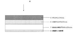
太陽電池モジュールは、表面保護シート、接着性樹脂層、光起電力素子、接着性樹脂層、裏面保護シートからなる太陽電池モジュールが広く知られている。 As the solar cell module, a solar cell module including a surface protective sheet, an adhesive resin layer, a photovoltaic element, an adhesive resin layer, and a back surface protective sheet is widely known.
最近は、非晶質シリコン等の半導体装置を利用した太陽電池が急速に普及しつつあり、一般住宅用の電源としても使用されるようになってきた。 Recently, solar cells using semiconductor devices such as amorphous silicon have been rapidly spreading and have been used as power sources for ordinary houses.
太陽電池を屋根部材と一体に構成して使用する際には、複数の太陽電池素子を組み合わせ、表裏面を適当なカバー材料で保護した太陽電池モジュールとして使用するのが一般的である。太陽電池の裏面保護シートとして、光反射フィルム、酸化物蒸着層、耐加水分解性ポリエステルフィルムを積層してなる方法も提案されている。 When a solar cell is used integrally with a roof member, it is generally used as a solar cell module in which a plurality of solar cell elements are combined and the front and back surfaces are protected with an appropriate cover material. As a back surface protection sheet for solar cells, a method of laminating a light reflecting film, an oxide vapor deposition layer, and a hydrolysis resistant polyester film has also been proposed.
太陽電池の裏面保護シートには、太陽電池モジュールを電圧印加による破損から保護する為にセルの発電容量に併せ部分放電電圧700Vもしくは1000Vの耐性が要求され電気絶縁性や発泡層を含むことで部分放電電圧を向上させる提案がなされている。耐部分放電電圧を向上させる方法として電気絶縁性を有するフィルムや発泡層を含む提案がなされているが(特許文献1参照)、高分子フィルムの耐部分放電電圧はフィルムの厚みに依存する為に厚膜となり断裁時の作業性悪化と共に必然的にコストが高くなるという問題があった。また、太陽電池モジュールとして長期間の屋外暴露において紫外線の影響を受け黄変しフィルム外観の美麗性が損なわれるという問題があった。
発明が解決しようとする課題は、太陽電池バックシートの部分放電電圧の向上を図ると共に太陽光の影響による屋外暴露面のプラスチックフィルムの黄変防止をすることであり、太陽電池セルを保護すると共に長期間安定性を維持することである。 The problem to be solved by the invention is to improve the partial discharge voltage of the solar battery back sheet and to prevent yellowing of the plastic film on the outdoor exposed surface due to the influence of sunlight, while protecting the solar battery cell It is to maintain stability for a long time.
本発明はかかる課題を解決するために次のような手段を採用するものである。
(1)耐加水分解性を有するプラスチックフィルムからなるB層と、B層に隣接し、表面抵抗値が1×10⁷〜1×10¹² Ω/□(以下同様に、表面抵抗値の単位はΩ/□)であり、かつ350〜360nm波長の平均透過率が5%以下であるA層とを有する太陽電池モジュール用裏面保護シート用フィルム。
(2)上記A層がアクリル樹脂と導電成分を含む(1)に記載の太陽電池モジュール用裏面保護シート用フィルム。
(3)上記導電成分が酸化亜鉛である(2)に記載の太陽電池モジュール用裏面保護シート用フィルム。
(4)促進耐候性試験機で上記A層側から紫外線強度100mW/cm2、48時間の紫外線照射前後での表色系bの差が10以下である(1)〜(3)のいずれかに記載の太陽電池モジュール用裏面保護シート用フィルム。
(5)加速寿命試験装置で120℃、100%RH、12時間保管後の表面抵抗値が、1×10¹² Ω/□以下であり、かつ350〜360nm波長の平均透過率が5%以下であるA層を有する(1)〜(4)のいずれかに記載の太陽電池モジュール用裏面保護シート用フィルム。
(6)少なくとも太陽光反射能を有するC層と接着能を有するD層とを有し、上記A層が屋外暴露面である(1)〜(5)のいずれかに記載の太陽電池モジュール用裏面保護シート。
(7)全厚みが170〜255μmであり、部分放電電圧が1000V以上である(6)記載の太陽電池モジュール用裏面保護シート。
(8)上記D層がポリエチレンフィルムである(6)〜(7)のいずれかに記載の太陽電池モジュール用裏面保護シート。
(9)上記C層が白色ポリエステルフィルムである(6)〜(8)のいずれかに記載の太陽電池モジュール用裏面保護シート。
(10)上記D層がポリエチレンフィルムであり、上記C層が白色ポリエステルフィルムである太陽電池モジュール用裏面保護シートであって、該ポリエチレンフィルムの非ラミネート面の表面にコロナ処理を施していない事を特徴とする(6)または(7)記載の太陽電池モジュール用裏面保護シート。
(11)(1)〜(10)のいずれかに記載の太陽電池モジュール用裏面保護シートを使用した太陽電池モジュール。
The present invention employs the following means in order to solve such problems.
(1) B layer made of a hydrolysis resistant plastic film, and adjacent to the B layer, the surface resistance value is 1 × 10 7 to 1 × 10 12 Ω / □ (hereinafter, the unit of the surface resistance value is the same) Ω / □) and an A layer having an average transmittance of 5% or less at a wavelength of 350 to 360 nm.
(2) The film for back surface protection sheet for solar cell modules as described in (1) in which the A layer contains an acrylic resin and a conductive component.
(3) The film for back surface protection sheet for solar cell modules as described in (2) whose said electroconductive component is zinc oxide.
(4) any of the A layer side in an accelerated weathering tester difference color system b at an ultraviolet irradiation before and after the UV intensity 100mW / cm 2, 48 hours is 10 or less (1) to (3) The film for back surface protection sheets for solar cell modules of description.
(5) The surface resistance value after storage at 120 ° C., 100% RH for 12 hours in an accelerated life test apparatus is 1 × 10 12 Ω / □ or less, and the average transmittance at a wavelength of 350 to 360 nm is 5% or less. The film for back surface protection sheets for solar cell modules in any one of (1)-(4) which has a certain A layer.
(6) The solar cell module according to any one of (1) to (5), which has at least a C layer having sunlight reflecting ability and a D layer having adhesive ability, and the A layer is an outdoor exposed surface. Back protection sheet.
(7) The back surface protective sheet for a solar cell module according to (6), wherein the total thickness is 170 to 255 μm and the partial discharge voltage is 1000 V or more.
(8) The back surface protective sheet for solar cell modules according to any one of (6) to (7), wherein the D layer is a polyethylene film.
(9) The back surface protective sheet for a solar cell module according to any one of (6) to (8), wherein the C layer is a white polyester film.
(10) The back protective sheet for a solar cell module, in which the D layer is a polyethylene film and the C layer is a white polyester film, and the non-laminated surface of the polyethylene film is not subjected to corona treatment. The back surface protection sheet for solar cell modules as described in (6) or (7).
(11) A solar cell module using the back protective sheet for a solar cell module according to any one of (1) to (10).
本発明の太陽電池モジュールの裏面保護シートは、太陽電池の部分放電電圧を向上させ太陽電池セルを保護する性能を持つ。
本発明の太陽電池モジュールの裏面保護シートは、紫外線の影響による屋外暴露される面の黄変を抑える。
The back surface protection sheet of the solar cell module of the present invention has the performance of improving the partial discharge voltage of the solar cell and protecting the solar cell.
The back surface protection sheet of the solar cell module of the present invention suppresses yellowing of the surface exposed outdoors due to the influence of ultraviolet rays.
本発明の太陽電池モジュールの裏面保護シートは、太陽電池モジュールに裏面保護シートを熱圧着する時の水蒸気遮断性の劣化を抑える。 The back surface protection sheet of the solar cell module of the present invention suppresses deterioration of water vapor barrier properties when the back surface protection sheet is thermocompression bonded to the solar cell module.
本発明の太陽電池モジュールの裏面保護シートは、太陽電池モジュールに裏面保護シートを熱圧着する際に収縮が小さい。 The back surface protection sheet of the solar cell module of the present invention has small shrinkage when the back surface protection sheet is thermocompression bonded to the solar cell module.
本発明の太陽電池モジュールの裏面保護シートは、吸湿による、モジュールの発電性能の低下が小さく、入射した光を有効に反射させて再利用し、太陽電池の電力変換効率を高める。 The back surface protection sheet of the solar cell module of the present invention has a small decrease in the power generation performance of the module due to moisture absorption, effectively reflects incident light and reuses it, and increases the power conversion efficiency of the solar cell.
本発明は、基材シートの屋外暴露される面に表面抵抗値1×107から×1012範囲であり、かつ350〜360nm波長の平均透過率が5%以下である塗工層を有した太陽電池モジュール用裏面保護シートである。 The present invention has a coating layer having a surface resistance value in the range of 1 × 10 7 to × 10 12 and an average transmittance of 350 to 360 nm wavelength of 5% or less on the surface of the base sheet that is exposed outdoors. It is a back surface protection sheet for solar cell modules.
本発明の太陽電池モジュール用裏面保護シートは、基材シート屋外暴露面の表面に、導電層と紫外線遮断層の積層もしくは導電層と紫外線遮断層を兼ねた層(A層)を有する。導電層をA層中に有することで、部分放電電圧が向上する。 The back surface protection sheet for solar cell modules of this invention has a layer (A layer) which laminated | stacked the conductive layer and the ultraviolet-blocking layer on the surface of the base material sheet outdoor exposure surface, or served as the conductive layer and the ultraviolet-blocking layer. By having the conductive layer in the A layer, the partial discharge voltage is improved.
なお、導電層と紫外線遮断層を積層する場合は導電層が最外層となる。ここでいう紫外線遮断層とは紫外線吸収剤を含有する層を指し、導電層とは、導電成分を含有する層を指す。 When the conductive layer and the ultraviolet blocking layer are laminated, the conductive layer is the outermost layer. Here, the ultraviolet blocking layer refers to a layer containing an ultraviolet absorber, and the conductive layer refers to a layer containing a conductive component.
本発明の太陽電池裏面保護シート用フィルムにおけるA層に用いられる導電成分が有機系導電成分の場合、非イオン性の有機系導電成分とイオン性の有機系導電成分のいずれも用いることができる。 When the conductive component used for the A layer in the solar cell back surface protective sheet film of the present invention is an organic conductive component, any of a nonionic organic conductive component and an ionic organic conductive component can be used.
非イオン性の有機系導電成分としては、例えば、エチレングリコール、ジエチレングリコール、トリエチレングリコール、グリセリン、トリメチロールプロパン、ペンタエルスリット、ソルビット等の多価アルコールおよび/またはその脂肪酸エステルや、ポリエチレングリコールおよび/またはその脂肪酸エステルや、高級アルコール、多価アルコール、アルキルフェノールのポリエチレングリコール付加物またはポリプロピレングリコール付加物などが挙げられる。中でもグリセリン脂肪酸エステル、ポリエチレングリコールおよび/またはその脂肪酸エステルが好適に用いられる。 Nonionic organic conductive components include, for example, polyhydric alcohols such as ethylene glycol, diethylene glycol, triethylene glycol, glycerin, trimethylolpropane, pentael slit, sorbit and / or fatty acid esters thereof, polyethylene glycol and / or Alternatively, fatty acid esters thereof, higher alcohols, polyhydric alcohols, polyethylene glycol adducts or polypropylene glycol adducts of alkylphenols can be used. Of these, glycerin fatty acid ester, polyethylene glycol and / or fatty acid ester thereof are preferably used.
多価アルコールは、そのままでも使用することができるが、脂肪酸とのエステル化反応によって脂肪酸エステルとすることがより望ましい。 The polyhydric alcohol can be used as it is, but it is more preferable to use a fatty acid ester by esterification with a fatty acid.
脂肪酸は、特に限定されないが、ラウリン酸(C12)、バルチミン酸(C16)、ステアリン酸(C18)、ベヘン酸(C22)等の飽和脂肪酸や、パルミトレイン酸、オレイン酸、エルカ酸、リノール酸等の不飽和脂肪酸等が、コスト上有利に用いられる。
また、ヤシ油脂肪酸、大豆油脂肪酸、牛脂脂肪酸、イワシ油脂肪酸等、および天然物由来の混合脂肪酸を用いることもできる。
Fatty acids are not particularly limited, but are saturated fatty acids such as lauric acid (C12), valtic acid (C16), stearic acid (C18), behenic acid (C22), palmitoleic acid, oleic acid, erucic acid, linoleic acid, etc. Unsaturated fatty acids and the like are advantageously used in terms of cost.
Moreover, coconut oil fatty acid, soybean oil fatty acid, beef tallow fatty acid, sardine oil fatty acid and the like, and mixed fatty acids derived from natural products can also be used.
また、多価アルコールがこれら脂肪酸でエステル化される場合には、多価アルコールの分子構造単位当たり少なくとも1つの水酸基が残存することが好ましい。
有機系導電成分としてポリエチレングリコールおよび/またはその脂肪酸エステルを使用する場合、ポリエチレングリコールは、エチレンオキシドの繰り返し単位が、4〜10000のものが好ましく、中でも100〜8000のものが好ましく、特に1000〜6000のものが特に好ましく用いられる。
When the polyhydric alcohol is esterified with these fatty acids, it is preferable that at least one hydroxyl group remains per molecular structural unit of the polyhydric alcohol.
When polyethylene glycol and / or a fatty acid ester thereof is used as the organic conductive component, polyethylene glycol preferably has an ethylene oxide repeating unit of 4 to 10,000, more preferably 100 to 8000, and particularly preferably 1000 to 6000. Those are particularly preferably used.
ポリエチレングリコールは、有機系導電成分としてそのままでも使用することができるが、さらに、脂肪酸エステル化する場合は、末端の水酸基を残存させても、末端の水酸基を残存させなくてもよい。 Polyethylene glycol can be used as it is as an organic conductive component. However, in the case of fatty acid esterification, the terminal hydroxyl group may or may not remain.
有機系導電成分として、高級アルコールのポリエチレングリコール付加物またはポリプロピレングリコール付加物を使用する場合、高級アルコールは、炭素数6以上のものであれば特に限定されないが、工業的に入手しやすい代表的なものとして、ノニルアルコール、デシルアルコール、ラウリルアルコール、ミリスチルアルコール、セチルアルコール、ステアリルアルコール、およびオレイルアルコール等の第1アルコールを挙げることができる。
マッコウアルコールやホホバアルコール等の混合物や、牛脂アルコール、およびヤシアルコール等の還元アルコールを用いることもできる。
When a higher alcohol polyethylene glycol adduct or a polypropylene glycol adduct is used as the organic conductive component, the higher alcohol is not particularly limited as long as it has 6 or more carbon atoms. Mention may be made of primary alcohols such as nonyl alcohol, decyl alcohol, lauryl alcohol, myristyl alcohol, cetyl alcohol, stearyl alcohol and oleyl alcohol.
Mixtures such as sperm alcohol and jojoba alcohol, and reduced alcohols such as beef tallow alcohol and coconut alcohol can also be used.
有機系導電成分として、アルキルフェノールのポリエチレングリコール付加物またはポリプロピレングリコール付加物を使用する場合、アルキルフェノールとしては、ノニルフェノール、ドデシルフェノール、オクチルフェノール、オクチルクレゾール等が挙げられる。 When an alkylphenol polyethylene glycol adduct or polypropylene glycol adduct is used as the organic conductive component, examples of the alkylphenol include nonylphenol, dodecylphenol, octylphenol, octylcresol and the like.
イオン性の有機系導電成分としては、例えば、アルキルスルホン酸塩、アルキルベンゼンスルホン酸塩、アルキルナフタリンスルホン酸塩、アルキルジフェニルスルホン酸塩等のスルホン酸塩、アルキルリン酸エステル、アルキル亜リン酸塩、アルキルホスホン酸塩、アルキルホスホン酸エステル等の含リン化合物などのアニオン性有機系導電成分や、第4級アンモニウムクロライド、第4級アンモニウムサルフェート、第4級アンモニウムナイトレートなどのカチオン性有機系導電成分が挙げられる。中でも、アルキルスルホン酸塩、アルキルベンゼンスルホン酸塩、および、アルキルホスホン酸塩などのアニオン性有機系導電成分が、耐熱性の点から好ましく用いられ、特にアルキルスルホン酸塩が好ましく用いられる。 Examples of ionic organic conductive components include sulfonates such as alkyl sulfonates, alkyl benzene sulfonates, alkyl naphthalene sulfonates, and alkyl diphenyl sulfonates, alkyl phosphate esters, alkyl phosphites, Anionic organic conductive components such as phosphorus-containing compounds such as alkylphosphonates and alkylphosphonic acid esters, and cationic organic conductive components such as quaternary ammonium chloride, quaternary ammonium sulfate, and quaternary ammonium nitrate Is mentioned. Among these, anionic organic conductive components such as alkyl sulfonate, alkyl benzene sulfonate, and alkyl phosphonate are preferably used from the viewpoint of heat resistance, and alkyl sulfonate is particularly preferably used.
有機系導電成分の添加量についてはB層の表面抵抗値が1×10⁷〜1×10¹² となる範囲で適宜調整する。 About the addition amount of an organic type electroconductive component, it adjusts suitably in the range from which the surface resistance value of B layer is set to 1 * 10 < 7 > -1 * 10 < 12 >.
導電層には有機系導電成分に加えて、ポリエステル系樹脂、アクリル系樹脂、ポリオレフィン系樹脂、ポリアミド系樹脂、ポリカーボネート、ポリスチレン、ポリエーテル、ポリエステルアミド、ポリエーテルエステル、ポリ塩化ビニル、ポリビニルアルコールおよびこれらを成分とする共重合体などの非水溶性樹脂をバインダー樹脂として混合することも好ましく行われるが、紫外線による劣化防止の面から特にアクリル系樹脂が望ましい。アクリル系樹脂としては、例えばポリアクリル酸やそのエステルおよびポリメタクリル酸とそのエステルなどが挙げられ、アクリル酸メチルおよびアクリル酸エチルが好ましい。 In addition to organic conductive components, the conductive layer includes polyester resin, acrylic resin, polyolefin resin, polyamide resin, polycarbonate, polystyrene, polyether, polyesteramide, polyetherester, polyvinyl chloride, polyvinyl alcohol, and these. It is also preferable to mix a water-insoluble resin such as a copolymer containing as a binder resin as a binder resin, but an acrylic resin is particularly desirable from the viewpoint of preventing deterioration due to ultraviolet rays. Examples of the acrylic resin include polyacrylic acid and esters thereof, polymethacrylic acid and esters thereof, and methyl acrylate and ethyl acrylate are preferable.
また、耐湿熱特性を更に向上、基材層との密着性向上、耐ブロッキング防止等の点で、有機系導電成分、バインダー樹脂に加えて、架橋剤を含有することも好ましく行われる。架橋剤としては、上述の有機系導電成分および/またはバインダー樹脂を構成する樹脂に存在する官能基、例えばヒドロキシル基、カルボキシル基、グリシジル基、アミド基等と架橋反応する樹脂や化合物が好ましく用いられ、その例としてはメチロール化あるいはアルキロール化した尿素系、メラミン系、アクリルアミド系、ポリアミド系樹脂及びエポキシ化合物、イソシアネート化合物、カップリング剤、アジリジン化合物、オキサゾリン化合物等、及びそれらの混合物等を使用することができる。 In addition to the organic conductive component and the binder resin, it is also preferable to contain a crosslinking agent in terms of further improving the wet heat resistance, improving the adhesion with the base material layer, and preventing blocking. As the crosslinking agent, a resin or a compound that undergoes a crosslinking reaction with a functional group present in the resin constituting the organic conductive component and / or the binder resin, for example, a hydroxyl group, a carboxyl group, a glycidyl group, an amide group, or the like is preferably used. Examples thereof include methylolated or alkylolated urea, melamine, acrylamide, polyamide resins and epoxy compounds, isocyanate compounds, coupling agents, aziridine compounds, oxazoline compounds, and mixtures thereof. be able to.
かかる架橋剤の種類、および含有量は、耐加水分解性を有するプラスチックフィルムからなる層(B層)、A層に含有される有機系導電成分、バインダー樹脂等によって適宜選択される。本発明における架橋剤としては、有機系導電成分および/またはバインダー樹脂がアクリル系骨格を有する場合は、架橋剤としてはオキサゾリン化合物が、有機系導電成分および/またはバインダー樹脂がポリエステル系骨格を有する場合は、架橋剤としてはメラミン系化合物が、形成されるA層が耐湿熱特性により優れるという点でより好ましい。上記オキサゾリン化合物としては2−オキサゾリジンが、上記メラミン系化合物としてはメチロール化メラミンが挙げられる。また、架橋剤の添加量は、通常はA層を構成する全樹脂成分100重量部に対し、0.01〜50重量部が好ましく、より好ましくは0.2〜40重量部、更に好ましくは0.5〜30重量部がより好ましい。ここで、架橋剤には、触媒を併用して架橋反応を促進させることも好ましく行われる。なお、架橋反応方式としては、加熱方式、電磁波照射方式、吸湿方式などのいずれでも構わないが、通常は加熱による方法が好ましく用いられる。 The kind and content of the crosslinking agent are appropriately selected depending on a layer (B layer) made of a plastic film having hydrolysis resistance, an organic conductive component contained in the A layer, a binder resin, and the like. As the crosslinking agent in the present invention, when the organic conductive component and / or binder resin has an acrylic skeleton, the oxazoline compound as the crosslinking agent, and when the organic conductive component and / or binder resin has a polyester skeleton Is more preferably a melamine-based compound as a cross-linking agent in that the formed layer A is superior in heat and moisture resistance. Examples of the oxazoline compound include 2-oxazolidine, and examples of the melamine compound include methylolated melamine. Moreover, the addition amount of the crosslinking agent is preferably 0.01 to 50 parts by weight, more preferably 0.2 to 40 parts by weight, and still more preferably 0 to 100 parts by weight of the total resin components constituting the A layer. More preferably, it is 5 to 30 parts by weight. Here, the crosslinking agent is also preferably used in combination with a catalyst to promote the crosslinking reaction. In addition, as a crosslinking reaction system, any of a heating system, an electromagnetic wave irradiation system, a moisture absorption system, etc. may be used, but usually a method by heating is preferably used.
また、本発明の太陽電池裏面保護シート用フィルムにおけるA層に用いられる導電成分が無機系導電成分の場合、無機系導電成分の例としては、金、銀、銅、白金、ケイ素、硼素、パラジウム、レニウム、バナジウム、オスミウム、コバルト、鉄、亜鉛、ルテニウム、プラセオジウム、クロム、ニッケル、アルミニウム、スズ、亜鉛、チタン、タンタル、ジルコニウム、アンチモン、インジウム、イットリウム、ランタニウム、マグネシウム、カルシウム、セリウム、ハフニウム、バリウム、等の無機物群を主たる成分とするものを酸化、亜酸化、次亜酸化させたもの、もしくは上記無機物群と上記無機物群を酸化、亜酸化、次亜酸化させたものとの混合物(以後これらを無機酸化物と称する)、上記無機物群を主たる成分とするものを窒化、亜窒化、次亜窒化させたもの、もしくは上記無機物群と上記無機物群を窒化、亜窒化、次亜窒化したものとの混合物(以後これらを無機窒化物と称する)、上記無機物群を主たる成分とするものを酸窒化、亜酸窒化、次亜酸窒化させたもの、もしくは上記無機物群と上記無機物群を酸窒化、亜酸窒化、次亜酸窒化させたものの混合物(以後これらを無機酸窒化物と称する)、上記無機物群を主たる成分とするものを炭化、亜炭化、次亜炭化させたもの、もしくは上記無機物群と上記無機物群を炭化、亜炭化、次亜炭化させたものとの混合物(以後これらを称して無機炭化物とする)、上記無機物群を主たる成分とするものをフッ化および/または塩素化および/または臭化および/またはヨウ化(以下、これらをハロゲン化とする)、亜ハロゲン化、次亜ハロゲン化させたもの、上記無機物群と上記無機物群をハロゲン化、亜ハロゲン化、次亜ハロゲン化させたものとの混合物(以後これらを称して無機ハロゲン化物とする)、もしくは上記無機物群と上記無機物群を硫化、亜硫化、次亜硫化させたものとの混合物(以後これらを称して無機硫化物とする)、およびグラファイト状カーボン、ダイヤモンドライクカーボンなどの炭素系化合物(以後これらを称し炭素系化合物とする)、およびこれらの混合物などが挙げられる。上記成分はA層中に少なくとも含んでいればよいが、より好ましくは主たる成分とすることがよい。なお、該層中において50重量%を越える場合を主たる成分と定義する。 In addition, when the conductive component used in the A layer in the film for protecting a back surface of a solar cell of the present invention is an inorganic conductive component, examples of the inorganic conductive component include gold, silver, copper, platinum, silicon, boron, palladium. , Rhenium, vanadium, osmium, cobalt, iron, zinc, ruthenium, praseodymium, chromium, nickel, aluminum, tin, zinc, titanium, tantalum, zirconium, antimony, indium, yttrium, lanthanum, magnesium, calcium, cerium, hafnium, barium Those containing an inorganic group as the main component, such as oxidized, sub-oxidized, hypo-sub-oxidized, or a mixture of the inorganic group and the inorganic group oxidized, sub-oxidized, sub-oxidized (hereinafter referred to as these) Is referred to as an inorganic oxide), and nitriding the main component of the above inorganic group Sub-nitrided, hypo-sub-nitrided, or a mixture of the inorganic group and the inorganic group nitrided, sub-nitrided, sub-nitrided (hereinafter referred to as inorganic nitride), the inorganic group as the main components Or oxynitride, oxynitride, hypooxynitride, or a mixture of the above inorganic group and the above inorganic group oxynitride, oxynitride, hyponitronitride (hereinafter referred to as inorganic oxynitride) ), Carbonized, sub-carbonized, hypo-sub-carbonized one containing the inorganic group as a main component, or a mixture of the inorganic group and the inorganic group carbonized, sub-carbonized, hypo-carbonized ( Hereinafter, these are referred to as inorganic carbides), and those containing the above inorganic group as the main component are fluorinated and / or chlorinated and / or brominated and / or iodinated (hereinafter referred to as halogenated), C Genogenated, hypohalogenated, a mixture of the above inorganic group and the above inorganic group halogenated, subhalogenated, hypohalated (hereinafter referred to as inorganic halide), or Mixtures of the above inorganic group and those obtained by sulfiding, subsulfiding or hyposulfiding the inorganic group (hereinafter referred to as inorganic sulfides), and carbon-based compounds such as graphitic carbon and diamond-like carbon These are referred to as carbon-based compounds), and mixtures thereof. Although the said component should just be contained at least in A layer, More preferably, it is good to set it as the main component. In addition, the case where it exceeds 50 weight% in this layer is defined as a main component.
また、導電成分として、微粒子状の形態の無機系導電成分を用いる場合は、基材への密着性、機械的強度向上などを付与するためにバインダー樹脂、架橋剤、有機系導電成分などとの併用が好ましく行われる。 In addition, when an inorganic conductive component in the form of fine particles is used as the conductive component, the binder resin, the cross-linking agent, the organic conductive component, etc. are used to impart adhesion to the substrate and mechanical strength improvement. The combined use is preferably performed.
また、本発明の太陽電池裏面保護シート用フィルムのA層には、基材の紫外線劣化を防ぐために紫外線遮断層を有する必要がある。紫外線遮断層をA層中に有することで、長期の紫外線の照射を受けても、A層の部分放電電圧の向上効果を長期間維持でき、A層、B層、C層、D層の紫外線による色調変化、強度劣化等が防止される。 In addition, the A layer of the film for solar cell back surface protective sheet of the present invention needs to have an ultraviolet blocking layer in order to prevent ultraviolet degradation of the substrate. By having the ultraviolet blocking layer in the A layer, the effect of improving the partial discharge voltage of the A layer can be maintained for a long time even when irradiated with ultraviolet rays for a long time, and the ultraviolet rays of the A layer, B layer, C layer, and D layer are maintained. Color tone change, strength deterioration, and the like due to are prevented.
本発明における紫外線吸収剤は、他の特性が損なわれない範囲であれば、有機系紫外線吸収剤、無機系紫外線吸収剤、およびこれらの併用、いずれも特に限定されずに好ましく用いることができるが、耐湿熱性に優れ、A層中に均一に均一分散できることが望まれる。このような紫外線吸収剤の例としては、例えば、有機系の紫外線吸収剤の場合は、サリチル酸系、ベンゾフェノン系、ベンゾトリアゾール系、シアノアクリレート系等の紫外線吸収剤およびヒンダードアミン系等の紫外線安定剤などが挙げられる。具体的には、例えば、サリチル酸系のp−t−ブチルフェニルサリシレート、p−オクチルフェニルサリシレート、ベンゾフェノン系の2,4−ジヒドロキシベンゾフェノン、2−ヒドロキシ−4−メトキシベンゾフェノン、2−ヒドロキシ−4−メトキシ−5−スルホベンゾフェノン、2,2’,4,4’−テトラヒドロキシベンゾフェノン、ビス(2−メトキシ−4−ヒドロキシ−5−ベンゾイルフェニル)メタン、ベンゾトリアゾール系の2−(2’−ヒドロキシ−5’−メチルフェニル)ベンゾトリアゾール、2−(2’−ヒドロキシ−5’−メチルフェニル)ベンゾトリアゾール、2,2’−メチレンビス[4−(1,1,3,3−テトラメチルブチル)−6−(2Hベンゾトリアゾール−2−イル)フェノール]、シアノアクリレート系のエチル−2−シアノ−3,3’−ジフェニルアクリレート)、その他として、および2−(4,6−ジフェニル−1,3,5−トリアジン−2−イル)−5−[(ヘキシル)オキシ]−フェノール、ヒンダードアミン系のビス(2,2,6,6−テトラメチル−4−ピペリジル)セバケート、コハク酸ジメチル・1−(2−ヒドロキシエチル)−4−ヒドロキシ−2,2,6,6−テトラメチルピペリジン重縮合物、それ他として、ニッケルビス(オクチルフェニル)サルファイド、および2,4−ジ・t−ブチルフェニル−3’,5’−ジ・t−ブチル−4’−ヒドロキシベンゾエートなどが挙げられる。なお、これらの紫外線吸収剤は上述の紫外線吸収剤単体でA層に添加しても良いし、有機系導電成分や、バインダー樹脂に紫外線吸収剤能を有するモノマーを共重合させた形態で導入してもよい。 The ultraviolet absorber in the present invention can be preferably used without any particular limitation, as long as other properties are not impaired, any of organic ultraviolet absorbers, inorganic ultraviolet absorbers, and combinations thereof. It is desirable that it has excellent heat and humidity resistance and can be uniformly and uniformly dispersed in the A layer. Examples of such ultraviolet absorbers include, for example, in the case of organic ultraviolet absorbers, salicylic acid-based, benzophenone-based, benzotriazole-based, cyanoacrylate-based ultraviolet absorbers, hindered amine-based ultraviolet stabilizers, etc. Is mentioned. Specifically, for example, salicylic acid-based pt-butylphenyl salicylate, p-octylphenyl salicylate, benzophenone-based 2,4-dihydroxybenzophenone, 2-hydroxy-4-methoxybenzophenone, 2-hydroxy-4-methoxy -5-sulfobenzophenone, 2,2 ', 4,4'-tetrahydroxybenzophenone, bis (2-methoxy-4-hydroxy-5-benzoylphenyl) methane, 2- (2'-hydroxy-5) of benzotriazole series '-Methylphenyl) benzotriazole, 2- (2'-hydroxy-5'-methylphenyl) benzotriazole, 2,2'-methylenebis [4- (1,1,3,3-tetramethylbutyl) -6- (2H benzotriazol-2-yl) phenol], a cyanoacrylate-based ester Ru-2-cyano-3,3′-diphenyl acrylate), as others, and 2- (4,6-diphenyl-1,3,5-triazin-2-yl) -5-[(hexyl) oxy]- Phenol, hindered amine bis (2,2,6,6-tetramethyl-4-piperidyl) sebacate, dimethyl succinate 1- (2-hydroxyethyl) -4-hydroxy-2,2,6,6-tetra Examples include methylpiperidine polycondensate, nickel bis (octylphenyl) sulfide, and 2,4-di-t-butylphenyl-3 ′, 5′-di-t-butyl-4′-hydroxybenzoate. It is done. These ultraviolet absorbers may be added to the A layer as a single ultraviolet absorber as described above, or may be introduced in a form in which an organic conductive component or a binder resin is copolymerized with a monomer having an ultraviolet absorber ability. May be.
また、無機系の紫外線吸収剤としては、酸化チタン、酸化亜鉛、酸化セリウム、などの金属酸化物や、カーボン、フラーレン、カーボンファイバー、カーボンナノチューブなどの炭素系成分等が挙げられる。 Examples of inorganic ultraviolet absorbers include metal oxides such as titanium oxide, zinc oxide, and cerium oxide, and carbon-based components such as carbon, fullerene, carbon fiber, and carbon nanotube.
また、上記紫外線吸収剤は、単独でも2種類以上の併用であってもよく、無機系、有機系の化合物を併用してもよいが、無機系導電成分としての機能兼用および導電性の温湿度安定性を考えた場合、無機系導電成分と同一が望ましく、中でも加速寿命試験装置で120℃、100%RH、12時間保管後の表面抵抗値劣化を考えた場合、酸化亜鉛が最適である。 In addition, the ultraviolet absorber may be used alone or in combination of two or more kinds, and an inorganic or organic compound may be used in combination. When considering stability, it is desirable to be the same as the inorganic conductive component, and zinc oxide is most suitable when considering deterioration of surface resistance after storage at 120 ° C., 100% RH for 12 hours with an accelerated life test apparatus.
本発明の太陽電池裏面保護シート用フィルムのA層における紫外線吸収剤の含有量は、有機系紫外線吸収剤の場合、A層中の全固形成分に対して0.05〜20重量%であることが好ましく、より好ましくは0.1〜15重量%であり、さらに好ましくは0.15〜15重量%である。紫外線吸収剤の含有量が0.05重量%未満の場合には、耐光性が不十分で、長期使用時において、A層が劣化し、部分放電電圧が低下することがあるため好ましくなく、また、20重量%より多いと、A層の着色が大きくなることがあるため好ましくない。 In the case of the organic ultraviolet absorber, the content of the ultraviolet absorber in the layer A of the solar cell back surface protective sheet film of the present invention is 0.05 to 20% by weight with respect to the total solid components in the layer A. Is more preferable, 0.1 to 15% by weight, still more preferably 0.15 to 15% by weight. When the content of the ultraviolet absorber is less than 0.05% by weight, the light resistance is insufficient, and the layer A is deteriorated during long-term use, and the partial discharge voltage may be lowered. If it is more than 20% by weight, coloring of the A layer may increase, which is not preferable.
また無機系紫外線吸収剤の場合はA層の全固形成分に対して10〜50重量%、より好ましくは15〜45重量%であり、さらに好ましくは20〜40重量%である。無機系紫外線吸収剤の場合は、紫外線吸収剤の含有量が1重量%未満の場合には、耐光性が不十分で、長期使用時において、A層が劣化し、部分放電電圧が低下することがあるため好ましくなく、また、40重量%より多いと、A層の強度が低下することがあったりするため、好ましくない。 Moreover, in the case of an inorganic type ultraviolet absorber, it is 10 to 50 weight% with respect to the total solid component of A layer, More preferably, it is 15 to 45 weight%, More preferably, it is 20 to 40 weight%. In the case of inorganic UV absorbers, if the UV absorber content is less than 1% by weight, the light resistance is insufficient, and the layer A deteriorates and the partial discharge voltage decreases during long-term use. In addition, it is not preferable, and if it is more than 40% by weight, the strength of the A layer may decrease, which is not preferable.
A層の厚みは、A層を構成する成分が有機系成分を主たる構成成分とした場合、通常0.5〜10μmが好ましく、より好ましくは1.0〜10μm、さらに好ましくは2.0〜10μmの範囲内である。また、A層を構成する成分が無機系成分を主たる構成成分とした場合、0.5〜10μmが好ましく、より好ましくは1.0〜10μm、さらに好ましくは3.0〜5.0μmの範囲内である。A層の厚みを上述の範囲に制御することによって、部分放電電圧の向上効果、A層の形成性、均一性、低コストなどを両立することができる。 The thickness of the A layer is usually preferably 0.5 to 10 μm, more preferably 1.0 to 10 μm, and still more preferably 2.0 to 10 μm, when the components constituting the A layer are mainly organic components. Is within the range. Moreover, when the component which comprises A layer makes an inorganic type component main component, 0.5-10 micrometers is preferable, More preferably, it is 1.0-10 micrometers, More preferably, it exists in the range of 3.0-5.0 micrometers. It is. By controlling the thickness of the A layer within the above range, it is possible to achieve both the effect of improving the partial discharge voltage, the formability, uniformity, and low cost of the A layer.
本発明において、A層の表面抵抗値は、部分放電電圧の向上効果を得る為には、1×10⁷から5×10¹²である必要があり、好ましくは、1×10⁷から1×10¹²以下である。A層の表面抵抗値が1×10⁷未満では、部分放電電圧の向上効果が低くなる。一方、A層の表面抵抗値が5×10¹²を越えると部分放電電圧の向上効果が十分でない。表面抵抗値は、太陽電池の屋外使用を考えた場合、紫外線や雨等の自然環境下においても、1×10⁷から1×10¹²であることが望ましい。なお、本発明において、A層が導電層と紫外線遮断層の積層の場合、A層の表面抵抗値とは導電層の表面抵抗値を指す。 In the present invention, the surface resistance value of the A layer needs to be 1 × 10 7 to 5 × 10 12 in order to obtain the effect of improving the partial discharge voltage, and preferably 1 × 10 7 to 1 × 10 6. 12 or less. When the surface resistance value of the A layer is less than 1 × 10 7 , the effect of improving the partial discharge voltage is lowered. On the other hand, if the surface resistance value of the A layer exceeds 5 × 10 12 , the effect of improving the partial discharge voltage is not sufficient. The surface resistance value is preferably 1 × 10 7 to 1 × 10 12 even in a natural environment such as ultraviolet rays or rain, considering the outdoor use of solar cells. In the present invention, when the A layer is a laminate of a conductive layer and an ultraviolet blocking layer, the surface resistance value of the A layer refers to the surface resistance value of the conductive layer.
本発明において、A層を構成する成分が有機系導電成分の場合、A層の表面抵抗値は有機系導電成分の種類、バインダー樹脂や架橋剤の種類と混合割合、その他成分との混合割合、A層厚み等によって決まる。A層に含まれる有機系導電成分に対しバインダー樹脂や架橋剤の割合が大きいほど表面抵抗値が高くなり、小さいほど表面抵抗値が小さくなる。また、A層厚みが厚いほど表面抵抗値が低くなり、薄いほど表面抵抗値が高くなる。最適な組成、A層厚みなどは、使用する有機系導電成分などにより変わるが、表面抵抗値が上述の要件を満たす様に形成される。 In the present invention, when the component constituting the A layer is an organic conductive component, the surface resistance value of the A layer is the type of the organic conductive component, the type and mixing ratio of the binder resin and the crosslinking agent, the mixing ratio with other components, It depends on the thickness of the A layer. The larger the ratio of the binder resin and the crosslinking agent to the organic conductive component contained in the A layer, the higher the surface resistance value, and the smaller, the smaller the surface resistance value. Further, the thicker the A layer, the lower the surface resistance value, and the thinner, the higher the surface resistance value. The optimum composition, the thickness of the A layer, and the like vary depending on the organic conductive component used, but the surface resistance value is formed so as to satisfy the above requirements.
本発明の太陽電池裏面保護シート用フィルムにおいて、A層を構成する成分が無機系導電成分の場合、A層の表面抵抗値は該無機物群の変性(酸化、窒化、酸窒化、炭化、ハロゲン化、硫化など)の度合いや、無機物群と変性した無機物群との混合割合、その他材料との混合割合、膜厚等によって決まる。無機物群の変性の度合いが高いほど表面抵抗値が高くなり、変性度合いが低いほど表面抵抗値が小さくなる。また、A層に含まれる無機物群に対し変性した無機物群の割合が大きいほど表面抵抗値が高くなり、小さいほど表面抵抗値が小さくなる。また、膜厚が厚いほど表面抵抗値が低くなり、小さいほど表面抵抗値が高くなる。最適な組成、膜厚は使用する金属種や、変性方式などにより変わるが、表面抵抗値が上述の要件を満たす様に形成される。 In the solar cell back surface protective sheet film of the present invention, when the component constituting the A layer is an inorganic conductive component, the surface resistance value of the A layer is modified (oxidation, nitridation, oxynitridation, carbonization, halogenation) of the inorganic substance group. , Sulfurization, etc.), the mixing ratio between the inorganic group and the modified inorganic group, the mixing ratio with other materials, the film thickness, and the like. The higher the degree of modification of the inorganic group, the higher the surface resistance value, and the lower the degree of modification, the smaller the surface resistance value. Moreover, the surface resistance value increases as the ratio of the modified inorganic group to the inorganic group included in the A layer increases, and the surface resistance value decreases as the ratio decreases. Further, the thicker the film thickness, the lower the surface resistance value, and the smaller the film thickness, the higher the surface resistance value. The optimum composition and film thickness vary depending on the type of metal used and the modification method, but the surface resistance value is formed so as to satisfy the above-mentioned requirements.
本発明の太陽電池モジュール用裏面保護シートは、促進耐候性試験機でA層側から紫外線強度100mW/cm2、48時間紫外線照射後のA層の表面抵抗値が、保管前に比べ10倍以下であり、かつ1×1012以下であるである事が望ましい。 The back surface protection sheet for solar cell modules of the present invention has an ultraviolet resistance of 100 mW / cm 2 from the A layer side with an accelerated weathering tester, and the surface resistance value of the A layer after 48 hours of ultraviolet irradiation is 10 times or less than before storage. It is desirable that it is 1 × 10 12 or less.
本発明の太陽電池モジュール用裏面保護シートは、A層中に紫外線遮断層を有することで耐久性を向上させることができる。耐久性としては、例えば、加速寿命試験装置で120℃、100%RHの条件下で12時間保管後のA層の表面抵抗値が、1×10¹²以下であり、かつ350〜360nm波長の平均透過率が5%以下であることが好ましい。なお、ここでいう加速寿命試験装置は、湿熱紫外線照射強制試験を指す。紫外線による黄変は可視光線以下の近紫外線領域350〜360nm波長が顕著であり、この波長における平均透過率が5%以上の場合、太陽光の紫外線を受け屋外暴露でのフィルム黄変が促進される。 The back surface protection sheet for solar cell modules of this invention can improve durability by having an ultraviolet shielding layer in A layer. As the durability, for example, the surface resistance value of the A layer after storage for 12 hours under the conditions of 120 ° C. and 100% RH in an accelerated life test apparatus is 1 × 10 12 or less, and the average of 350 to 360 nm wavelength The transmittance is preferably 5% or less. In addition, the accelerated life test apparatus here refers to a wet heat ultraviolet irradiation forced test. Yellowing due to ultraviolet rays is remarkable in the near-ultraviolet region of 350 to 360 nm wavelength below visible light. When the average transmittance at this wavelength is 5% or more, film yellowing in outdoor exposure is promoted by receiving ultraviolet rays from sunlight. The
本発明の太陽電池モジュール用裏面保護シートは、屋外暴露される面の表面には導電層及び紫外線遮断層を有するが、もう一方の面には、導電層を有しない。本発明の太陽電池モジュール用裏面保護シートは、導電層非形成面の表面抵抗値は、2×10¹³以上であることが好ましく、より好ましくは、1×10¹⁴以上である。導電層非形成面の表面抵抗値が、2×10¹³未満の場合は、部分放電電圧向上効果は低減する場合がある。 The back surface protective sheet for a solar cell module of the present invention has a conductive layer and an ultraviolet blocking layer on the surface exposed to the outdoors, but does not have a conductive layer on the other surface. In the back surface protective sheet for a solar cell module of the present invention, the surface resistance value of the surface on which the conductive layer is not formed is preferably 2 × 10 13 or more, more preferably 1 × 10 14 or more. When the surface resistance value of the surface where the conductive layer is not formed is less than 2 × 10 13 , the partial discharge voltage improvement effect may be reduced.
本発明におけるA層は、耐加水分解性を有するプラスチックフィルムからなる層(B層)にコーティングにより形成するのが一般的である。コーティング方法はグラビアコート法、ダイコート法などの公知の方法を用いることができ、グラビアコート法がより好ましい。 The A layer in the present invention is generally formed by coating on a layer (B layer) made of a plastic film having hydrolysis resistance. As the coating method, a known method such as a gravure coating method or a die coating method can be used, and the gravure coating method is more preferable.
本発明におけるB層は、耐加水分解性を有するプラスチックフィルムからなり、より好ましくは、耐加水分解性を有するポリエステルフィルム、さらに好ましくは、ポリエチレンフィルムとポリエステルフィルムとの積層フィルムである。 B layer in this invention consists of a plastic film which has hydrolysis resistance, More preferably, it is a polyester film which has hydrolysis resistance, More preferably, it is a laminated film of a polyethylene film and a polyester film.
耐加水分解を有するポリエステルフィルムとは、140℃高圧スチームで10時間保管後の引張伸度がフィルムの縦方向、横方向共に、60%以上を保持するポリエステルフィルムを指す。 The polyester film having hydrolysis resistance refers to a polyester film having a tensile elongation of 60% or more in both the machine direction and the transverse direction after storage for 10 hours at 140 ° C. high pressure steam.
140℃高圧スチームで10時間保管後の引張伸度がフィルムの縦方向、横方向共に、60%以上を保持するポリエステルフィルムとしては、JIS C2151(1996確認)によりフィルムの破断伸度を測定したとき、140℃高圧スチーム条件下でスチーム処理前と比較し、50%伸度低下時間が耐加水分解性を有しないフィルムの2倍以上になるポリエステルフィルムが上市されており、B層として用いることができる。140℃高圧スチームで10時間保管後の引張伸度がフィルムの縦方向、横方向共に、60%以上を保持するポリエステルフィルムとしては、ポリエチレンテレフタレートの二軸延伸フィルムが、加工性、透明性、耐熱性、価格の面から好ましい。 When the elongation at break of the film is measured according to JIS C2151 (1996 confirmation) as a polyester film in which the tensile elongation after storage at 140 ° C. high pressure steam for 10 hours holds 60% or more in both the longitudinal and transverse directions of the film. A polyester film that has a 50% elongation reduction time more than twice that of a film having no hydrolysis resistance compared to that before steam treatment under high-pressure steam conditions at 140 ° C. is marketed and can be used as the B layer. it can. As a polyester film whose tensile elongation after storage for 10 hours in high-pressure steam at 140 ° C is 60% or more in both the machine direction and the transverse direction, a biaxially stretched film of polyethylene terephthalate is workability, transparency and heat resistance. It is preferable in terms of sex and price.
本発明の太陽電池モジュール用裏面保護シートにおいて、B層には、各種の添加剤が含有されていても良く、添加剤として、例えば、帯電防止剤、UV吸収剤、安定剤等が挙げられる。 In the back surface protective sheet for a solar cell module of the present invention, the B layer may contain various additives, and examples of the additive include an antistatic agent, a UV absorber, and a stabilizer.
本発明において、C層は太陽光を反射させ発電効率を上げる為に使用する。C層としては、例えば、白色ポリエステルフィルムや白色ポリエチレンフィルムを用いることができる。白色ポリエステルフィルムとしては、波長λ=550nmの反射率が、30%以上のポリエステルフィルムが好ましく、より好ましくは、反射率が40%以上のポリエステルフィルムであり、さらに好ましくは、反射率が50%以上のポリエステルフィルムである。 In the present invention, the C layer is used to reflect sunlight and increase power generation efficiency. As the C layer, for example, a white polyester film or a white polyethylene film can be used. The white polyester film is preferably a polyester film having a reflectance of wavelength λ = 550 nm of 30% or more, more preferably a polyester film having a reflectance of 40% or more, and further preferably a reflectance of 50% or more. It is a polyester film.
また、C層として、ポリエステルフィルムの内部に微細な気泡を含有させたポリエステルフィルムを用いてもよい。 Moreover, you may use the polyester film which made the inside of a polyester film contain a fine bubble as C layer.
本発明において、C層として白色ポリエステルフィルムおよび白色ポリエチレンフィルムを使用する場合、白色に着色する方法は、好ましくは、酸化チタン、シリカ、アルミナ、炭酸カルシウム、硫酸バリウム等の白色添加物を添加する。さらに白色度を高めるためにはチオフェンジイル等の蛍光増白剤を用いると効果的である。 In the present invention, when a white polyester film and a white polyethylene film are used as the C layer, it is preferable to add a white additive such as titanium oxide, silica, alumina, calcium carbonate, or barium sulfate as a method of coloring white. In order to further increase the whiteness, it is effective to use a fluorescent whitening agent such as thiophenediyl.
本発明の太陽電池モジュール用裏面保護シートの全厚みは170〜255μmであることが好ましく、経済性の観点からより好ましくは170〜230μmであり、100〜225μmであることがさらに好ましい。厚みが255μmを越えると、部分放電電圧が向上するが、カットする際の断裁性が悪くなる場合があり、さらに、加工工程でのカール影響により太陽電池セルとの熱圧着作業性が悪くなる場合がある。一方、フィルムの厚みが170μm未満の場合、配線透過が増加し、美観が悪くなる場合があると共に部分放電電圧が低下するため望ましくない。また、耐候性が十分でなく光起電力素子を十分保護できない。 The total thickness of the back surface protective sheet for a solar cell module of the present invention is preferably 170 to 255 μm, more preferably 170 to 230 μm, and even more preferably 100 to 225 μm from the viewpoint of economy. When the thickness exceeds 255 μm, the partial discharge voltage is improved, but the cutting property when cutting may be deteriorated, and further, the thermocompression workability with the solar battery cell is deteriorated due to the curling effect in the processing process. There is. On the other hand, when the thickness of the film is less than 170 μm, the wiring permeation increases, the appearance may be deteriorated, and the partial discharge voltage is lowered, which is not desirable. Further, the weather resistance is not sufficient and the photovoltaic element cannot be sufficiently protected.
本発明の太陽電池モジュール用裏面保護シートにおいて、太陽電池モジュールの接着性樹脂層との安定した密着強度を得る為に、光照反射面の最表層に接着能を有するD層を位置させることが好ましい。D層としては、ポリエチレンフィルムを用いることが好ましい。ポリエチレンフィルムは公知のものを用いることができるが、更に好ましくは密度0.93〜0.94、融点130℃以下である直鎖状低密度ポリエチレンフィルムである。 In the back surface protective sheet for a solar cell module of the present invention, in order to obtain a stable adhesion strength with the adhesive resin layer of the solar cell module, it is preferable to position a D layer having an adhesive ability on the outermost layer of the light reflecting surface. . A polyethylene film is preferably used as the D layer. Although a well-known thing can be used for a polyethylene film, More preferably, it is a linear low density polyethylene film whose density is 0.93-0.94 and whose melting | fusing point is 130 degrees C or less.
接着性樹脂層に接する面の上記ポリエチレンフィルムは未処理であることが好ましい。コロナ処理等の表面処理を施した場合はポリエチレンフィルムの表面酸化により接着性樹脂層との密着強度が損なわれる。 The polyethylene film on the surface in contact with the adhesive resin layer is preferably untreated. When surface treatment such as corona treatment is performed, the adhesion strength with the adhesive resin layer is impaired by the surface oxidation of the polyethylene film.
本発明の太陽電池モジュール用裏面保護シートにおいて、好ましくは、光照反射反対面の最表層に、140℃高圧スチームで10時間保管後の引張伸度がフィルムの縦方向、横方向共に、60%以上を保持するポリエステルフィルムを位置することができる。
140℃高圧スチームで10時間保管後の引張伸度がフィルムの縦方向、横方向共に、60%以上を保持するポリエステルフィルムは、高透明で可撓性に富み、耐熱性、防湿性、耐加水分解に優れる性能を有し、好ましくは、太陽電池モジュールの保護を行う。
In the back surface protective sheet for a solar cell module of the present invention, preferably, the tensile elongation after storage for 10 hours with 140 ° C. high pressure steam is 60% or more in both the longitudinal and lateral directions of the film on the outermost surface opposite to the light reflecting and reflecting. A polyester film can be positioned.
Polyester film with a tensile elongation of 60% or more after storage for 10 hours in high-pressure steam at 140 ° C in both the machine direction and the transverse direction is highly transparent and flexible, and has heat resistance, moisture resistance, and water resistance. It has a performance superior in decomposition, and preferably protects the solar cell module.
本発明の太陽電池モジュール用裏面保護シートは、屋外暴露での紫外線影響によるフィルム黄変およびフィルム強度の低下防止の為、紫外線強度100mW/cm2の促進耐候性試験機で48時間紫外線照射後の表色系bが10以下であることが望ましく、更に好ましくは5以下である。表色系bが10以下では、黄変は目視で確認できない程度であり、十分な美麗性・フィルム強度が共に得られる。 The back protective sheet for solar cell module of the present invention is for 48 hours after UV irradiation with an accelerated weathering tester with an ultraviolet intensity of 100 mW / cm 2 in order to prevent film yellowing and film strength from being reduced due to the influence of ultraviolet rays when exposed outdoors. The color system b is desirably 10 or less, more preferably 5 or less. When the color system b is 10 or less, yellowing cannot be visually confirmed, and sufficient aesthetics and film strength can be obtained.
本発明の太陽電池モジュール用裏面保護シートの部分放電電圧は1000V以上であることが好ましく、より好ましくは1200V以上である。1000V以上とすることで、外部からの電荷による太陽電池セル破損を防止することができる。 It is preferable that the partial discharge voltage of the back surface protection sheet for solar cell modules of this invention is 1000V or more, More preferably, it is 1200V or more. By setting it to 1000 V or higher, it is possible to prevent damage to the solar battery cells due to external charges.
本発明の太陽電池モジュール用裏面保護シートは、屋外暴露面の表面に帯電防止及び紫外線遮断層を有することにより、帯電防止層及び紫外線遮断層を有しない面に比較して、好ましくは、部分放電電圧が20%以上、より好ましくは、30%以上、より好ましくは、35%以上向上すると共にフィルムの黄変に対し寄与の大きい350〜360nm波長の平均透過率が5%以下、好ましくは3%以下である。部分放電電圧向上率を上げるほど、ベースフィルムの薄膜化が出来、コストダウンが可能となり望ましい。 The back surface protection sheet for solar cell modules of the present invention preferably has a partial discharge by having an antistatic and ultraviolet blocking layer on the surface of the outdoor exposed surface, as compared to a surface having no antistatic and ultraviolet blocking layers. The average transmittance at a wavelength of 350 to 360 nm having a voltage of 20% or more, more preferably 30% or more, more preferably 35% or more and greatly contributing to yellowing of the film is 5% or less, preferably 3%. It is as follows. As the partial discharge voltage improvement rate is increased, it is desirable that the base film can be made thinner and the cost can be reduced.
本発明の太陽電池モジュール用裏面保護シートにおいて、40℃、90%RHにおける水蒸気透過率が、3.0g/m2・day以下が望ましく、要求される水蒸気遮断性に応じて積層体の厚みを変えることも可能である。 In the back surface protective sheet for a solar cell module of the present invention, the water vapor transmission rate at 40 ° C. and 90% RH is preferably 3.0 g / m 2 · day or less, and the thickness of the laminate is determined according to the required water vapor barrier property. It is also possible to change.
本発明の太陽電池モジュール用裏面保護シートは、必要に応じて、樹脂層を積層することができる。 As for the back surface protection sheet for solar cell modules of this invention, a resin layer can be laminated | stacked as needed.
本発明の太陽電池モジュール用裏面保護シートにおいて、樹脂層には、公知の熱安定剤、滑剤、帯電防止剤、耐ブロッキング剤、染料、顔料、光増感剤、界面活性剤、紫外線吸収剤などの各種添加剤を、必要に応じて添加することができる。 In the back surface protective sheet for the solar cell module of the present invention, the resin layer has a known heat stabilizer, lubricant, antistatic agent, anti-blocking agent, dye, pigment, photosensitizer, surfactant, ultraviolet absorber, etc. These various additives can be added as necessary.
本発明の太陽電池モジュール用裏面保護シートは、好ましくは、150℃、30分熱処理をしたときの収縮率が、縦方向,横方向共に0.5%以下である。 The back surface protection sheet for a solar cell module of the present invention preferably has a shrinkage rate of 0.5% or less in both the vertical and horizontal directions when heat-treated at 150 ° C. for 30 minutes.
太陽電池モジュールと裏面保護シートとを積層する際に、通常、接着樹脂層を、加熱溶融、圧着、冷却することにより一体化し形成する。加熱溶融、圧着は、通常、130〜150℃の温度で30分程度行われる。加熱溶融条件を考えた場合、本発明の太陽電池モジュール用裏面保護シートは、150℃,30分の熱処理における収縮率を、縦方向,横方向共に0.5%以下に抑えることが加工時のシワ抑制面から好ましい。 When laminating the solar cell module and the back surface protective sheet, usually, the adhesive resin layer is integrally formed by heating, melting, pressing and cooling. Heat melting and pressure bonding are usually performed at a temperature of 130 to 150 ° C. for about 30 minutes. When considering the heating and melting conditions, the back surface protective sheet for solar cell module of the present invention can suppress the shrinkage ratio in heat treatment at 150 ° C. for 30 minutes to 0.5% or less in both the vertical and horizontal directions during processing. It is preferable from the viewpoint of wrinkle suppression.
太陽電池モジュール用裏面保護シートの150℃,30分の熱処理における収縮率は、より好ましくは、縦方向、1.0%以下、横方向、1.0%以下であり、より好ましくは、縦方向、0.5%以下、横方向、0.5%以下である。 The shrinkage rate in the heat treatment at 150 ° C. for 30 minutes of the back surface protective sheet for solar cell module is more preferably the vertical direction, 1.0% or less, the horizontal direction, 1.0% or less, and more preferably the vertical direction. 0.5% or less, lateral direction, 0.5% or less.
太陽電池モジュール用裏面保護シートの150℃,30分の熱処理における収縮率を、縦方向,横方向共に0.5%以下に抑える方法としては、例えば、アニール処理により、事前に加工フィルムに熱を与える事により収縮させ、後工程において熱が加わるラミネートや熱圧着等の工程での収縮を防ぐ技術が知られている。 As a method of suppressing the shrinkage rate in the heat treatment at 150 ° C. for 30 minutes of the back surface protection sheet for the solar cell module to 0.5% or less in both the vertical direction and the horizontal direction, for example, heat is applied to the processed film in advance by annealing treatment. A technique is known in which shrinkage is applied to prevent shrinkage in processes such as lamination and thermocompression, in which heat is applied in a subsequent process.
太陽電池モジュール用裏面保護シートの150℃,30分熱処理後の水蒸気透過率の増加率は、熱処理前の水蒸気透過率に比べて、30%未満であることが好ましく、10%未満であることがより好ましい。 The increase rate of the water vapor transmission rate after heat treatment at 150 ° C. for 30 minutes of the back surface protective sheet for solar cell module is preferably less than 30%, and preferably less than 10%, compared with the water vapor transmission rate before the heat treatment. More preferred.
本発明の太陽電池モジュール用裏面保護シートにおいて、D層としてポリエチレンフィルム、C層として白色ポリエステルフィルム、B層として140℃高圧スチームで10時間保管後の引張伸度がフィルムの縦方向、横方向共に、60%以上を保持するポリエステルフィルムをこの順番に積層して接着することが好ましい。接着の方法としては、例えば、接着剤を一方のフィルムに塗布したのち、もう一方のフィルムと重ね合せ、加圧あるいは、加熱下で接着する方法などを用いることができる。 In the back surface protection sheet for solar cell modules of the present invention, the tensile elongation after storage for 10 hours with a polyethylene film as the D layer, the white polyester film as the C layer, and 140 ° C. high-pressure steam as the B layer is the longitudinal and lateral directions of the film. It is preferable to laminate and adhere polyester films that hold 60% or more in this order. As a bonding method, for example, a method in which an adhesive is applied to one film and then superposed on the other film and bonded under pressure or heating can be used.
ポリエチレンフィルム、白色ポリエステルフィルム、140℃高圧スチームで10時間保管後の引張伸度がフィルムの縦方向、横方向共に、60%以上を保持するポリエステルフィルムの接着に用いられる接着剤として代表的なものは、アクリル樹脂、ウレタン樹脂、エポキシ樹脂、ポリエステル樹脂,ポリアミド、フェノール、ポリオレフィン、アイオノマー、エチレン酢ビ共重合体、ポリビニルアセタールなど、およびこれらの共重合体や、混合物などが挙げられる。 Typical adhesive used for bonding polyethylene film, white polyester film, polyester film with tensile elongation after storage for 10 hours at 140 ° C high-pressure steam in both the longitudinal and transverse directions of 60% or more. Examples thereof include acrylic resins, urethane resins, epoxy resins, polyester resins, polyamides, phenols, polyolefins, ionomers, ethylene vinyl acetate copolymers, polyvinyl acetals and the like, and copolymers and mixtures thereof.
接着剤は、ウレタン樹脂、ポリエステル樹脂,ポリオレフィン、アイオノマーが、接着力および、ガスバリア性の点で好ましく、最も好ましくは、ウレタン樹脂であることが望ましい。 The adhesive is preferably a urethane resin, a polyester resin, a polyolefin, or an ionomer in terms of adhesive strength and gas barrier properties, and most preferably a urethane resin.
上記接着剤の厚みは、接着力の観点から、1.0〜10μmが好ましい。更に好ましくは、2.0〜8μmであり、特に好ましくは、3.0〜5μmである。 The thickness of the adhesive is preferably 1.0 to 10 μm from the viewpoint of adhesive strength. More preferably, it is 2.0-8 micrometers, Most preferably, it is 3.0-5 micrometers.
太陽電池モジュールの構成としては、図1に示すように、表面ガラス1、光起電力素子2、接着性樹脂層3、および、裏面保護シート4、のものが広く知られている。 As a structure of a solar cell module, as shown in FIG. 1, the surface glass 1, the photovoltaic element 2, the adhesive resin layer 3, and the back surface protection sheet 4 are widely known.
太陽電池モジュール用裏面保護シートは、樹脂接着層を介して、光起電力素子、樹脂接着層、表面保護シートと積層し、接着樹脂層を加熱溶融、圧着、冷却することにより、太陽電池モジュールとして一体化し形成されるのが一般的である。 The back surface protection sheet for solar cell modules is laminated with a photovoltaic element, a resin adhesive layer, and a surface protection sheet via a resin adhesive layer, and the adhesive resin layer is heated, melted, pressure-bonded and cooled as a solar cell module. In general, they are integrally formed.
太陽電池モジュールの樹脂接着層は、光起電力素子の凹凸を被覆し、素子を温度変化、湿度、衝撃などから保護し、かつ太陽電池モジュール用表面保護シートとの接着性を確保する目的で使用される。太陽電池モジュールの樹脂接着層としては、公知の接着性フィルムを使用することができ、例えば、エチレン−酢酸ビニル共重合体、エチレン−アクリル酸メチル共重合体、エチレン−アクリル酸エチル共重合体、ウレタン樹脂、ポリビニルブチラール、ポリビニルブチラール、エチレン−酢酸ビニル部分鹸化物、シリコーン樹脂、ポリエステル系樹脂等を挙げることができる。太陽電池モジュールの樹脂接着層は、耐光性、透過性、耐湿性、経済性の点からエチレン−酢酸ビニルが特に好ましく用いられ、酢酸ビニル含有量が樹脂接着層を構成する全樹脂成分に対して15〜40重量%のものが特に好ましい。太陽電池モジュールの樹脂接着層の酢酸ビニル含有量が15〜40重量%であると、透明性が低下せず、樹脂のべたつきがなく、加工性や取り扱い性がよい。 The resin adhesive layer of the solar cell module covers the unevenness of the photovoltaic element, protects the element from temperature changes, humidity, impact, etc., and is used for the purpose of ensuring adhesion with the surface protection sheet for solar cell module Is done. As the resin adhesive layer of the solar cell module, a known adhesive film can be used. For example, an ethylene-vinyl acetate copolymer, an ethylene-methyl acrylate copolymer, an ethylene-ethyl acrylate copolymer, Examples include urethane resin, polyvinyl butyral, polyvinyl butyral, partially saponified ethylene-vinyl acetate, silicone resin, and polyester resin. As the resin adhesive layer of the solar cell module, ethylene-vinyl acetate is particularly preferably used from the viewpoint of light resistance, transparency, moisture resistance, and economy, and the vinyl acetate content is based on the total resin components constituting the resin adhesive layer. A content of 15 to 40% by weight is particularly preferable. When the vinyl acetate content of the resin adhesive layer of the solar cell module is 15 to 40% by weight, the transparency is not lowered, the resin is not sticky, and the workability and handleability are good.
太陽電池モジュールの樹脂接着層には、必要に応じて、有機過酸化物などの架橋剤、紫外線吸収剤、酸化防止剤等添加剤を使用することができる。また、加熱溶融時のシワの発生を軽減し、加工性を向上させるため、予めエンボス加工を施した樹脂シートを使用してもよい。 For the resin adhesive layer of the solar cell module, additives such as a crosslinking agent such as an organic peroxide, an ultraviolet absorber, and an antioxidant can be used as necessary. Moreover, in order to reduce the generation | occurrence | production of the wrinkle at the time of heat-melting and to improve workability, you may use the resin sheet which gave the embossing previously.
以下、本発明の実施の形態を図面に基づいて説明する。なお、図に示すものは一実施例であり、これに限定されるものではない。 Hereinafter, embodiments of the present invention will be described with reference to the drawings. In addition, what is shown in a figure is one Example, It is not limited to this.
図1は、太陽電池用裏面保護シートの一実施形態の例を説明する側断面図である。表面ガラス1、光起電力素子2、接着性樹脂層3、および、裏面保護シート4によって構成される。外部からの光は、表面ガラスから入射し、接着性樹脂層3を通り、光起電力素子2に到達し、起電力が生ずる。また、裏面保護シートに反射した光が、光起電力素子2に到達し、起電力が生ずる。 FIG. 1 is a side sectional view for explaining an example of one embodiment of a back surface protection sheet for solar cells. It is comprised by the surface glass 1, the photovoltaic element 2, the adhesive resin layer 3, and the back surface protection sheet 4. FIG. Light from the outside enters from the surface glass, passes through the adhesive resin layer 3, reaches the photovoltaic element 2, and an electromotive force is generated. Moreover, the light reflected by the back surface protection sheet reaches the photovoltaic element 2 to generate an electromotive force.
図2は、本発明の太陽電池モジュール用裏面保護シートの一例を示す断面模式図である。光照射面側からポリエチレンフィルム(D層)、白色ポリエステル(C層)、140℃高圧スチームで10時間保管後の引張伸度がフィルムの縦方向、横方向共に、60%以上を保持するポリエステルフィルム(B層)を順番に積層してなる基材シートに塗工層(A層)を設けている。 FIG. 2 is a schematic cross-sectional view showing an example of the back surface protection sheet for a solar cell module of the present invention. Polyethylene film (D layer), white polyester (C layer) from the light-irradiated surface side, polyester film with a tensile elongation of 60% or more in both the vertical and horizontal directions of the film after storage at 140 ° C. high pressure steam for 10 hours The coating layer (A layer) is provided in the base material sheet formed by laminating (B layer) in order.
以下に実施例を挙げて本発明を説明する。実施例および比較例中の部数は、固形分の重量を示し、また、%は特に断りのない限り重量%である。実施例および比較例における本発明の特性値は、以下に示す測定方法ならびに評価基準によるものである。また、サンプル採取は製品幅方向3点とし、測定回数各10回の最大、最小値を除した数値の平均値とした。 Hereinafter, the present invention will be described with reference to examples. The number of parts in Examples and Comparative Examples indicates the weight of solid content, and% is% by weight unless otherwise specified. The characteristic values of the present invention in Examples and Comparative Examples are based on the following measurement methods and evaluation criteria. Samples were collected at 3 points in the product width direction, and the average value of the numerical values excluding the maximum and minimum values for each measurement count of 10 times.
実施例および比較例中の接着層は、一方の材料に、ウレタン系接着剤層(東洋モートン(株)製「AD503」10部に同社製イソシアネート系硬化剤「CAT−10」1部の混合物)を塗布、熱風循環式オーブンにより80℃で2分間乾燥し、膜厚3μmとなるよう設けて、他の構成材料と貼り合わせ積層し、40℃オーブンにて48時間硬化エージングさせた。 The adhesive layer in the examples and comparative examples is a urethane adhesive layer (a mixture of 10 parts “AD503” manufactured by Toyo Morton Co., Ltd. and 1 part of the isocyanate-based curing agent “CAT-10” manufactured by Toyo Morton Co., Ltd.). And dried at 80 ° C. for 2 minutes in a hot air circulation oven, provided to have a film thickness of 3 μm, laminated and laminated with other constituent materials, and cured and aged in a 40 ° C. oven for 48 hours.
(1)表面抵抗値
(株)アドバンテスト社製のデジタル超高抵抗微小電流計R8340を用いて23℃,65%RH条件で測定した。
(1) Surface resistance value It measured on 23 degreeC and 65% RH conditions using the digital super high resistance microammeter R8340 by the company manufactured by Advantest.
(2)部分放電電圧
導電層がある場合の部分放電電圧は、菊水電子工業(株)社製部分放電試験器KPD2050を使用し、23℃,65%RH条件で帯電防止層面から電圧をかけ測定した。導電層がない場合の部分放電電圧は、菊水電子工業(株)社製部分放電試験器KPD2050を使用し、23℃,65%RH条件で、耐加水分解を有するポリエステルフィルム面から電圧をかけ測定した。
(2) Partial discharge voltage The partial discharge voltage when there is a conductive layer is measured by applying a voltage from the surface of the antistatic layer at 23 ° C. and 65% RH using a partial discharge tester KPD2050 manufactured by Kikusui Electronics Co., Ltd. did. The partial discharge voltage when there is no conductive layer was measured by applying a voltage from the polyester film surface having hydrolysis resistance at 23 ° C. and 65% RH using a partial discharge tester KPD2050 manufactured by Kikusui Electronics Co., Ltd. did.
(3)耐湿熱劣化
エスペック(株)社製の加速寿命試験装置HASTチャンバーEHS−221MDを用いて、120℃×100%RH雰囲気にて12時間保管後の表面抵抗値を測定した。
(3) Wet heat resistance deterioration
Using an accelerated life test apparatus HAST chamber EHS-221MD manufactured by ESPEC CORP., The surface resistance value after storage for 12 hours in a 120 ° C. × 100% RH atmosphere was measured.
(4) 紫外線劣化
促進耐候性試験機であるアイスーパーUVテスター SUV−W131:岩崎電気(株)を用いて、60℃×50%RH雰囲気にて紫外線強度100mW/cm2で48時間紫外線照射後の表面抵抗値及び表色系b値の測定を行った。
(4) Isuper UV tester SUV-W131 which is an ultraviolet deterioration accelerating weathering tester: Iwasaki Electric Co., Ltd., and then irradiated with ultraviolet rays at 60 ° C. × 50% RH atmosphere at an ultraviolet intensity of 100 mW / cm 2 for 48 hours. The surface resistance value and the color system b value were measured.
(5)熱収縮率
太陽電池モジュール用裏面保護シートをタバイ社製P−212オーブンにて150℃,30分の熱処理を行った。熱処理を実施する前後の熱収縮率を、株式会社ミツトヨ製のデジタルノギスを用いて測定した。
(5) Thermal contraction rate The back surface protection sheet for solar cell modules was heat-treated at 150 ° C. for 30 minutes in a Tabai P-212 oven. The heat shrinkage before and after the heat treatment was measured using a digital caliper manufactured by Mitutoyo Corporation.
(6)反射率
分光光度径U−3410((株)日立製作所製)に、φ60積分球130−063((株)日立製作所製)および10°傾斜スペーサーを取りつけた状態で、550nmの反射率をフィルムの両表面について求め、最大値を該フィルムの反射率とした。標準白色板はU−3410に添付のもの((株)日立製作所製)を用いた。
(6) Reflectance spectrophotometric diameter U-3410 (manufactured by Hitachi, Ltd.), with a 60-degree integrating sphere 130-063 (manufactured by Hitachi, Ltd.) and a 10 ° inclined spacer attached, a reflectance of 550 nm Was determined for both surfaces of the film, and the maximum value was defined as the reflectance of the film. The standard white plate attached to U-3410 (manufactured by Hitachi, Ltd.) was used.
(7)140℃高圧スチームで保管後の引張伸度保持率
JIS C2151(1996)に記載の測定方法で、幅15mm,長さ150mm,の試験片を用いて100mmのつまみ間隔とし、500mm/分の引張速度で、フィルムの引張伸度を測定した。
さらに、140℃高圧スチーム中に、所定の時間保管後のフィルムの引張伸度を、JIS C2151(1996)に記載の測定方法で、幅15mm,長さ150mmの試験片を用いて、100mmのつまみ間隔とし、500mm/分の引張速度で、測定した。
140℃高圧スチーム中に保管する前のフィルムの引張伸度と、140℃高圧スチーム中に保管後前のフィルムの引張伸度から、フィルムの引張伸度保持率を求めた。
(7) Tensile elongation retention after storage in 140 ° C. high pressure steam JIS C2151 (1996), using a test piece with a width of 15 mm and a length of 150 mm, and a knob spacing of 100 mm, 500 mm / min The tensile elongation of the film was measured at a tensile rate of.
Further, the tensile elongation of the film after storage for a predetermined time in 140 ° C. high-pressure steam is measured by a measuring method described in JIS C2151 (1996), using a test piece having a width of 15 mm and a length of 150 mm. The interval was measured at a tensile speed of 500 mm / min.
The tensile elongation retention rate of the film was determined from the tensile elongation of the film before storage in high-pressure steam at 140 ° C. and the tensile elongation of the film before storage in high-pressure steam at 140 ° C.
(8)表色系b値
ミノルタカメラ(株)社製の色彩色差計CR−100を用いてLab表示色の黄色味を示すb値を測定した。
(8) Color system b value The b value indicating the yellow color of the Lab display color was measured using a color difference meter CR-100 manufactured by Minolta Camera Co., Ltd.
(9)シートの厚み
A層、B層、C層およびD層を含めた厚みを全厚みとし、アンリツ製デジタルマイクロメーター「KC−351C型」を使用して測定した。
(9) Sheet thickness The total thickness including the A layer, B layer, C layer and D layer was measured using an Anritsu digital micrometer "KC-351C type".
(10)水蒸気透過率
MOCON社製PERMATRAN W−TWINを用いて、1992年8月1日制定の「プラスチックフィルム及びシートの水蒸気透過度試験方法(機器測定法)JIS K7129B法」に従い、40℃,90%RH条件で測定した。
(10) Water vapor transmission rate Using PERMATRAN W-TWIN manufactured by MOCON, according to “Water vapor transmission rate test method (instrument measurement method) JIS K7129B method of plastic film and sheet” established on August 1, 1992, 40 ° C. It measured on 90% RH conditions.
(11)平均透過率
日本精密光学社製SEP−H−S型積分球式ヘイズメーターを使用し、白色光線(1952年8月25日制定の色の表示方法−XYZ表色系及びX10Y10Z10表色系JIS Z8701で規定されるA光)での透過率を測定した。
(11) Average transmittance White light (color display method established on August 25, 1952-XYZ color system and X10Y10Z10 color system) using an SEP-HS type integrating sphere haze meter manufactured by Nippon Seimitsu Optical Co., Ltd. Transmittance at A light) defined by the system JIS Z8701 was measured.
[実施例1]
太陽電池モジュール用裏面保護シートの基材シートとして、東レフィルム加工株式会社製ポリエチレンフィルム厚さ50μmの密度0.94の4801(幅1000mm、長さ4000m)を用いた。
白色ポリエステルフィルムは、東レ株式会社製の厚さ50μmのE20(幅1000mm、長さ4000m)を岡崎機械工業社製のフィルムコーターを用いて160℃の乾燥温度にて60秒間処理し、150℃,30分熱処理後に収縮率0.2%となるフィルムを得た。波長λ=550nmの反射率は、89%であった。
[Example 1]
As a base sheet of the back surface protection sheet for solar cell modules, Toray Film Processing Co., Ltd. polyethylene film having a density of 0.94 4801 (width 1000 mm, length 4000 m) with a thickness of 50 μm was used.
The white polyester film was prepared by treating E50 (width 1000 mm, length 4000 m) manufactured by Toray Industries, Inc. with a thickness of 50 μm for 60 seconds at a drying temperature of 160 ° C. using a film coater manufactured by Okazaki Machinery Co., Ltd. A film having a shrinkage of 0.2% after heat treatment for 30 minutes was obtained. The reflectance at the wavelength λ = 550 nm was 89%.
140℃高圧スチームで10時間保管後の引張伸度がフィルムの縦方向、横方向共に、60%以上を保持するポリエステルフィルムとして、140℃高圧スチームで10時間保管後の引張伸度がフィルムの縦方向、横方向共に、80%を保持する東レ株式会社製の厚さ125μmのX10S(幅1000mm、長さ4000m)を用い、岡崎機械工業社製のフィルムコーターを用いて、160℃の乾燥温度にて60秒間処理した。このポリエステルフィルムの150℃,30分熱処理後の収縮率は、MD0.3%、TD0.1%であった。しかる後にアクリル樹脂に対して30%重量混合後にIPA70:水30比率にて希釈し、岡崎機械工業社製のフィルムコーターを用いて120℃の乾燥温度にて乾燥後の塗工層厚み3g/m2となるように形成した。 As a polyester film in which the tensile elongation after storage at 140 ° C high pressure steam for 10 hours is 60% or more in both the machine direction and the transverse direction, the tensile elongation after storage at 140 ° C high pressure steam for 10 hours is Using a film coater made by Okazaki Machine Industry Co., Ltd. using a film coater made by Okazaki Kikai Kogyo Co., Ltd., using Toray's 125 mm thick X10S (width 1000 mm, length 4000 m) that holds 80% in both direction and width. For 60 seconds. The shrinkage ratio of this polyester film after heat treatment at 150 ° C. for 30 minutes was MD 0.3% and TD 0.1%. Thereafter, after 30% by weight mixing with the acrylic resin, the coating layer was diluted at a ratio of IPA 70: water 30 and dried at a drying temperature of 120 ° C. using a film coater manufactured by Okazaki Machinery Co., Ltd. 3 g / m in thickness. 2 was formed.
ポリエチレンフィルム4801フィルムのコロナ処理面と熱処理を行ったE20貼合した後にX10Sを、アクリル系樹脂に酸化亜鉛を配合した外側になるように貼合し、40℃オーブンにて48時間硬化エージング後に実施例1の太陽電池モジュール用裏面保護シートを作製した。 After bonding E20 with heat treatment and corona-treated surface of polyethylene film 4801 film, X10S was bonded so that it would be the outside where zinc oxide was blended with acrylic resin, and carried out after curing for 48 hours in a 40 ° C oven. The back surface protection sheet for solar cell modules of Example 1 was produced.
実施例1の太陽電池モジュール用裏面保護シートでは、基材シートは、白色ポリエステルフィルム、140℃高圧スチームで10時間保管後の引張伸度がフィルムの縦方向、横方向共に、60%以上を保持するポリエステルフィルム(X10S)が積層されている。さらに、基材シートの片面、すなわち、X10Sの屋外暴露面に、厚さ3g/m2のアクリル系樹脂に酸化亜鉛を配合した層が形成され、同層の表面抵抗値は、1.0×1010であった。 In the back surface protection sheet for the solar cell module of Example 1, the base sheet is a white polyester film, and the tensile elongation after storage for 10 hours with high-pressure steam at 140 ° C. holds 60% or more in both the vertical and horizontal directions of the film. A polyester film (X10S) is laminated. Furthermore, a layer in which zinc oxide is blended with an acrylic resin having a thickness of 3 g / m 2 is formed on one side of the base sheet, that is, the outdoor exposed surface of X10S, and the surface resistance value of the same layer is 1.0 × 10 was 10 .
実施例1の太陽電池モジュール用裏面保護シート表面抵抗値の変化(劣化試験前、耐湿熱劣化後、)及び太陽電池モジュール用裏面保護シートの部分放電電圧測定結果(アクリル系樹脂に酸化亜鉛を配合層がある場合、ない場合)と、部分放電電圧向上率をを表1に示す。表1に示したシート厚み230μmは、実施例1の太陽電池モジュール用裏面保護シートの厚みである。実施例1の350〜360nm波長の平均透過率及び紫外線照射前後での表色系b値を表2に示す。 Change in surface resistance value of back surface protection sheet for solar cell module of Example 1 (before deterioration test and after heat and humidity resistance degradation) and partial discharge voltage measurement result of back surface protection sheet for solar cell module (blended with zinc oxide in acrylic resin) Table 1 shows the partial discharge voltage improvement rate with and without the layer. The sheet thickness 230 μm shown in Table 1 is the thickness of the back surface protective sheet for solar cell module of Example 1. Table 2 shows the average transmittance of 350 to 360 nm wavelength of Example 1 and the color system b value before and after ultraviolet irradiation.
[実施例2]
東レ株式会社製のX10Sの厚みを75μmとしたこと以外は実施例1と同様の方法で、実施例2の裏面保護シートを作製した。太陽電池モジュール用裏面保護シートの厚みは、230μmであった。
[Example 2]
A back protective sheet of Example 2 was produced in the same manner as in Example 1 except that the thickness of X10S manufactured by Toray Industries, Inc. was 75 μm. The thickness of the back surface protection sheet for solar cell modules was 230 micrometers.
[実施例3]
アクリル系樹脂に酸化亜鉛を配合層厚みを2.5g/m2となるようにしたこと以外は、実施例1と同様の方法で、実施例3の裏面保護シートを作製した。
[Example 3]
A back protective sheet of Example 3 was produced in the same manner as in Example 1 except that zinc oxide was added to the acrylic resin so that the blended layer thickness was 2.5 g / m 2 .
[実施例4]
アクリル系樹脂に酸化亜鉛を配合層厚みを2g/m2となるようにしたこと以外は、実施例1と同様の方法で、実施例4の裏面保護シートを作製した。
[Example 4]
A back protective sheet of Example 4 was produced in the same manner as in Example 1 except that zinc oxide was added to the acrylic resin so that the blended layer thickness was 2 g / m 2 .
[実施例5]
アクリル系樹脂に酸化亜鉛配合層厚みを1.8g/m2となるようにしたこと以外は、実施例1と同様の方法で、実施例4の裏面保護シートを作製した。
[Example 5]
A back protective sheet of Example 4 was produced in the same manner as in Example 1 except that the thickness of the zinc oxide-containing layer in the acrylic resin was 1.8 g / m 2 .
[実施例6]
東レ株式会社製の白色ポリエステルフィルムE20を75μmとしたこと以外は実施例1と同様の方法で、実施例5の裏面保護シートを作製した。太陽電池モジュール用裏面保護シートの厚みは、255μmであった。
[Example 6]
A back protective sheet of Example 5 was produced in the same manner as in Example 1 except that the white polyester film E20 manufactured by Toray Industries, Inc. was 75 μm. The thickness of the back surface protection sheet for solar cell modules was 255 micrometers.
[実施例7]
アクリル系樹脂に酸化亜鉛を配合層厚みを4.0g/m2となるようにしたこと以外は、実施例6と同様の方法で、実施例7の裏面保護シートを作製した。
[Example 7]
A back protective sheet of Example 7 was produced in the same manner as in Example 6 except that zinc oxide was added to the acrylic resin so that the blended layer thickness was 4.0 g / m 2 .
[比較例1]
アクリル系樹脂に酸化亜鉛を配合した層を形成しない事以外は実施例1と同様の方法で比較例1の裏面保護シートを作製した。
[Comparative Example 1]
A back protective sheet of Comparative Example 1 was produced in the same manner as in Example 1 except that a layer in which zinc oxide was blended with an acrylic resin was not formed.
[比較例2]
アクリル系樹脂に酸化亜鉛を配合した層を形成しない事以外は実施例2と同様の方法で比較例2の裏面保護シートを作製した。
[Comparative Example 2]
A back protective sheet of Comparative Example 2 was produced in the same manner as in Example 2 except that a layer in which zinc oxide was blended with acrylic resin was not formed.
[比較例3]
アクリル系樹脂に酸化亜鉛を配合した層を形成しない事以外は実施例6と同様の方法で比較例3の裏面保護シートを作製した。
[Comparative Example 3]
A back protective sheet of Comparative Example 3 was produced in the same manner as in Example 6 except that a layer in which zinc oxide was blended with acrylic resin was not formed.
[比較例4]
アクリル系樹脂に酸化亜鉛を配合層厚みを1.5g/m2となるようにしたこと以外は、実施例1と同様の方法で、比較例4の裏面保護シートを作製した。
[Comparative Example 4]
A back protective sheet of Comparative Example 4 was produced in the same manner as in Example 1 except that zinc oxide was added to the acrylic resin so that the blended layer thickness was 1.5 g / m 2 .
[比較例5]
アクリル系樹脂に酸化亜鉛を配合層厚みを1.0g/m2となるようにしたこと以外は、実施例1と同様の方法で、比較例5の裏面保護シートを作製した。
[Comparative Example 5]
A back protective sheet of Comparative Example 5 was produced in the same manner as in Example 1 except that zinc oxide was added to the acrylic resin so that the blended layer thickness was 1.0 g / m 2 .
[比較例6]
アクリル系樹脂に酸化亜鉛を配合層厚みを0.5g/m2となるようにしたこと以外は、実施例1と同様の方法で、比較例6の裏面保護シートを作製した。
[Comparative Example 6]
A back protective sheet of Comparative Example 6 was produced in the same manner as in Example 1 except that zinc oxide was added to the acrylic resin so that the blended layer thickness was 0.5 g / m 2 .
[比較例7]
アクリル系樹脂に酸化亜鉛を配合層厚みを6.0g/m2となるようにしたこと以外は、実施例6と同様の方法で、比較例7の裏面保護シートを作製した。
[Comparative Example 7]
A back protective sheet of Comparative Example 7 was produced in the same manner as in Example 6 except that zinc oxide was added to the acrylic resin so that the thickness of the blended layer was 6.0 g / m 2 .
[評価結果]
実施例1〜7、比較例1〜7で得られた裏面保護シートに対して、前記の方法により諸特性を測定し、表1および表2に各物性を示した。表1、2の評価結果から明らかなように、本発明の太陽電池用裏面保護シートは部分放電電圧が向上すると共に紫外線照射による変色が小さくすることが可能である。
[Evaluation results]
With respect to the back surface protective sheets obtained in Examples 1 to 7 and Comparative Examples 1 to 7, various properties were measured by the methods described above, and Table 1 and Table 2 show the respective physical properties. As is clear from the evaluation results in Tables 1 and 2, the back protective sheet for solar cells of the present invention can improve the partial discharge voltage and reduce discoloration due to ultraviolet irradiation.

太陽電池の部分放電電圧の向上を図ると共に太陽光の影響による屋外暴露面のプラスチックフィルムの黄変防止をすることであり、太陽電池セルを保護すると共に長期間使用による安定性を維持することが出来る。 It is intended to improve the partial discharge voltage of solar cells and to prevent yellowing of the plastic film on the outdoor exposed surface due to the influence of sunlight, and to protect solar cells and maintain stability after long-term use. I can do it.
1:表面ガラス
2:光起電力素子
3:接着性樹脂層
4:裏面保護シート
5:ポリエチレンフィルム
6:白色ポリエステルフィルム
7:耐加水分解を有するポリエステルフィルム
8:導電層+紫外線遮断層
1: Surface glass 2: Photovoltaic element 3: Adhesive resin layer 4: Back surface protective sheet 5: Polyethylene film 6: White polyester film 7: Polyester film having hydrolysis resistance 8: Conductive layer + UV blocking layer
Claims (11)
Priority Applications (1)
| Application Number | Priority Date | Filing Date | Title |
|---|---|---|---|
| JP2008259339A JP5136937B2 (en) | 2008-10-06 | 2008-10-06 | Film for back surface protection sheet for solar cell module, and solar cell module using the same |
Applications Claiming Priority (1)
| Application Number | Priority Date | Filing Date | Title |
|---|---|---|---|
| JP2008259339A JP5136937B2 (en) | 2008-10-06 | 2008-10-06 | Film for back surface protection sheet for solar cell module, and solar cell module using the same |
Publications (3)
| Publication Number | Publication Date |
|---|---|
| JP2010092958A JP2010092958A (en) | 2010-04-22 |
| JP2010092958A5 JP2010092958A5 (en) | 2011-08-04 |
| JP5136937B2 true JP5136937B2 (en) | 2013-02-06 |
Family
ID=42255423
Family Applications (1)
| Application Number | Title | Priority Date | Filing Date |
|---|---|---|---|
| JP2008259339A Expired - Fee Related JP5136937B2 (en) | 2008-10-06 | 2008-10-06 | Film for back surface protection sheet for solar cell module, and solar cell module using the same |
Country Status (1)
| Country | Link |
|---|---|
| JP (1) | JP5136937B2 (en) |
Families Citing this family (6)
| Publication number | Priority date | Publication date | Assignee | Title |
|---|---|---|---|---|
| EP2573824A4 (en) * | 2010-05-20 | 2015-08-19 | Toray Advanced Film Co Ltd | Backside protective sheet for solar cell module |
| CN103098230B (en) * | 2010-08-31 | 2016-03-16 | 东丽薄膜先端加工股份有限公司 | Solar module backside protective sheet and use its solar module |
| JP5621469B2 (en) * | 2010-09-27 | 2014-11-12 | 大日本印刷株式会社 | Back surface protection sheet for solar cell module, back surface integrated sheet for solar cell module, and solar cell module |
| JP5621470B2 (en) * | 2010-09-27 | 2014-11-12 | 大日本印刷株式会社 | Back surface protection sheet for solar cell module, back surface integrated sheet for solar cell module, and solar cell module |
| WO2012044017A2 (en) * | 2010-09-27 | 2012-04-05 | (주)배스팀 | Solar photovoltaic module having graphite sheet |
| JP2019207899A (en) * | 2016-09-29 | 2019-12-05 | 富士フイルム株式会社 | Front sheet for solar battery and manufacturing method of the same, and solar battery module |
Family Cites Families (3)
| Publication number | Priority date | Publication date | Assignee | Title |
|---|---|---|---|---|
| JPWO2007122936A1 (en) * | 2006-03-28 | 2009-09-03 | 東レフィルム加工株式会社 | Back protection sheet for solar cell module |
| JP2008085293A (en) * | 2006-08-30 | 2008-04-10 | Keiwa Inc | Back sheet for photovoltaic cell module and photovoltaic cell module employing the same |
| JP2008166338A (en) * | 2006-12-27 | 2008-07-17 | Toray Ind Inc | Solar cell module and sheet for sealing rear face of same |
-
2008
- 2008-10-06 JP JP2008259339A patent/JP5136937B2/en not_active Expired - Fee Related
Also Published As
| Publication number | Publication date |
|---|---|
| JP2010092958A (en) | 2010-04-22 |
Similar Documents
| Publication | Publication Date | Title |
|---|---|---|
| JP5365140B2 (en) | Solar battery backsheet | |
| EP1898470B1 (en) | Use of a back sheet for photovoltaic modules and resulting photovoltaic module | |
| JPWO2007122936A1 (en) | Back protection sheet for solar cell module | |
| JP5115777B2 (en) | Surface protection sheet for solar cell module | |
| JP5136937B2 (en) | Film for back surface protection sheet for solar cell module, and solar cell module using the same | |
| JP5686397B2 (en) | Film for solar cell backsheet, solar cell backsheet using the same, and solar cell | |
| JP5301107B2 (en) | Back sheet for solar cell module and solar cell module using the same | |
| EP2573824A1 (en) | Backside protective sheet for solar cell module | |
| EP2800148B1 (en) | Protective sheet | |
| JP5214087B2 (en) | Back sheet for solar cell module and solar cell module using the same | |
| JP2008085293A (en) | Back sheet for photovoltaic cell module and photovoltaic cell module employing the same | |
| JP4992530B2 (en) | Back protection sheet for solar cells | |
| JP5109273B2 (en) | Surface protection sheet for solar cell module | |
| JP5156172B2 (en) | Back sheet for solar cell module and solar cell module using the same | |
| KR20160138104A (en) | Solar cell back sheet and solar cell module | |
| JP2009147063A (en) | Rear surface protection sheet for solar cell module | |
| WO2010050343A1 (en) | Solar battery rear surface protection sheet and solar battery module | |
| WO2014156518A1 (en) | Solar cell module production method | |
| JP2012253203A (en) | Rear surface protective sheet for solar cell module and solar cell module using the same | |
| JP2017139285A (en) | Rear surface protective sheet for solar cell module and method of manufacturing the sane, and method of manufacturing solar cell module | |
| JP6596812B2 (en) | Insulation sheet for solar cell | |
| JP2017183618A (en) | Backside protection sheet for solar battery module | |
| US20140190557A1 (en) | Method for producing solar cell module, solar cell backside sealing sheet, and solar cell module | |
| JP2013183112A (en) | Film for solar cell module front sheet | |
| JP5673936B2 (en) | Front sheet for solar cell module, solar cell module using the same, and method for producing front sheet for solar cell module |
Legal Events
| Date | Code | Title | Description |
|---|---|---|---|
| RD02 | Notification of acceptance of power of attorney |
Free format text: JAPANESE INTERMEDIATE CODE: A7422 Effective date: 20100226 |
|
| RD04 | Notification of resignation of power of attorney |
Free format text: JAPANESE INTERMEDIATE CODE: A7424 Effective date: 20100226 |
|
| A521 | Request for written amendment filed |
Free format text: JAPANESE INTERMEDIATE CODE: A523 Effective date: 20110620 |
|
| A621 | Written request for application examination |
Free format text: JAPANESE INTERMEDIATE CODE: A621 Effective date: 20110620 |
|
| RD02 | Notification of acceptance of power of attorney |
Free format text: JAPANESE INTERMEDIATE CODE: A7422 Effective date: 20110620 |
|
| RD04 | Notification of resignation of power of attorney |
Free format text: JAPANESE INTERMEDIATE CODE: A7424 Effective date: 20110620 |
|
| A977 | Report on retrieval |
Free format text: JAPANESE INTERMEDIATE CODE: A971007 Effective date: 20120516 |
|
| A131 | Notification of reasons for refusal |
Free format text: JAPANESE INTERMEDIATE CODE: A131 Effective date: 20120731 |
|
| A521 | Request for written amendment filed |
Free format text: JAPANESE INTERMEDIATE CODE: A523 Effective date: 20120913 |
|
| TRDD | Decision of grant or rejection written | ||
| A01 | Written decision to grant a patent or to grant a registration (utility model) |
Free format text: JAPANESE INTERMEDIATE CODE: A01 Effective date: 20121016 |
|
| A01 | Written decision to grant a patent or to grant a registration (utility model) |
Free format text: JAPANESE INTERMEDIATE CODE: A01 |
|
| A61 | First payment of annual fees (during grant procedure) |
Free format text: JAPANESE INTERMEDIATE CODE: A61 Effective date: 20121102 |
|
| R150 | Certificate of patent or registration of utility model |
Free format text: JAPANESE INTERMEDIATE CODE: R150 |
|
| FPAY | Renewal fee payment (event date is renewal date of database) |
Free format text: PAYMENT UNTIL: 20151122 Year of fee payment: 3 |
|
| R250 | Receipt of annual fees |
Free format text: JAPANESE INTERMEDIATE CODE: R250 |
|
| R250 | Receipt of annual fees |
Free format text: JAPANESE INTERMEDIATE CODE: R250 |
|
| LAPS | Cancellation because of no payment of annual fees |