JP5133685B2 - Contamination control element mounting system and contamination control device - Google Patents
Contamination control element mounting system and contamination control device Download PDFInfo
- Publication number
- JP5133685B2 JP5133685B2 JP2007521689A JP2007521689A JP5133685B2 JP 5133685 B2 JP5133685 B2 JP 5133685B2 JP 2007521689 A JP2007521689 A JP 2007521689A JP 2007521689 A JP2007521689 A JP 2007521689A JP 5133685 B2 JP5133685 B2 JP 5133685B2
- Authority
- JP
- Japan
- Prior art keywords
- mounting system
- pollution control
- mat
- control element
- catalyst carrier
- Prior art date
- Legal status (The legal status is an assumption and is not a legal conclusion. Google has not performed a legal analysis and makes no representation as to the accuracy of the status listed.)
- Expired - Fee Related
Links
Images


Classifications
-
- F—MECHANICAL ENGINEERING; LIGHTING; HEATING; WEAPONS; BLASTING
- F01—MACHINES OR ENGINES IN GENERAL; ENGINE PLANTS IN GENERAL; STEAM ENGINES
- F01N—GAS-FLOW SILENCERS OR EXHAUST APPARATUS FOR MACHINES OR ENGINES IN GENERAL; GAS-FLOW SILENCERS OR EXHAUST APPARATUS FOR INTERNAL COMBUSTION ENGINES
- F01N3/00—Exhaust or silencing apparatus having means for purifying, rendering innocuous, or otherwise treating exhaust
- F01N3/08—Exhaust or silencing apparatus having means for purifying, rendering innocuous, or otherwise treating exhaust for rendering innocuous
- F01N3/10—Exhaust or silencing apparatus having means for purifying, rendering innocuous, or otherwise treating exhaust for rendering innocuous by thermal or catalytic conversion of noxious components of exhaust
- F01N3/24—Exhaust or silencing apparatus having means for purifying, rendering innocuous, or otherwise treating exhaust for rendering innocuous by thermal or catalytic conversion of noxious components of exhaust characterised by constructional aspects of converting apparatus
- F01N3/28—Construction of catalytic reactors
- F01N3/2839—Arrangements for mounting catalyst support in housing, e.g. with means for compensating thermal expansion or vibration
- F01N3/2853—Arrangements for mounting catalyst support in housing, e.g. with means for compensating thermal expansion or vibration using mats or gaskets between catalyst body and housing
-
- F—MECHANICAL ENGINEERING; LIGHTING; HEATING; WEAPONS; BLASTING
- F01—MACHINES OR ENGINES IN GENERAL; ENGINE PLANTS IN GENERAL; STEAM ENGINES
- F01N—GAS-FLOW SILENCERS OR EXHAUST APPARATUS FOR MACHINES OR ENGINES IN GENERAL; GAS-FLOW SILENCERS OR EXHAUST APPARATUS FOR INTERNAL COMBUSTION ENGINES
- F01N3/00—Exhaust or silencing apparatus having means for purifying, rendering innocuous, or otherwise treating exhaust
- F01N3/02—Exhaust or silencing apparatus having means for purifying, rendering innocuous, or otherwise treating exhaust for cooling, or for removing solid constituents of, exhaust
- F01N3/021—Exhaust or silencing apparatus having means for purifying, rendering innocuous, or otherwise treating exhaust for cooling, or for removing solid constituents of, exhaust by means of filters
- F01N3/0211—Arrangements for mounting filtering elements in housing, e.g. with means for compensating thermal expansion or vibration
-
- F—MECHANICAL ENGINEERING; LIGHTING; HEATING; WEAPONS; BLASTING
- F01—MACHINES OR ENGINES IN GENERAL; ENGINE PLANTS IN GENERAL; STEAM ENGINES
- F01N—GAS-FLOW SILENCERS OR EXHAUST APPARATUS FOR MACHINES OR ENGINES IN GENERAL; GAS-FLOW SILENCERS OR EXHAUST APPARATUS FOR INTERNAL COMBUSTION ENGINES
- F01N3/00—Exhaust or silencing apparatus having means for purifying, rendering innocuous, or otherwise treating exhaust
- F01N3/08—Exhaust or silencing apparatus having means for purifying, rendering innocuous, or otherwise treating exhaust for rendering innocuous
- F01N3/10—Exhaust or silencing apparatus having means for purifying, rendering innocuous, or otherwise treating exhaust for rendering innocuous by thermal or catalytic conversion of noxious components of exhaust
- F01N3/24—Exhaust or silencing apparatus having means for purifying, rendering innocuous, or otherwise treating exhaust for rendering innocuous by thermal or catalytic conversion of noxious components of exhaust characterised by constructional aspects of converting apparatus
- F01N3/28—Construction of catalytic reactors
- F01N3/2839—Arrangements for mounting catalyst support in housing, e.g. with means for compensating thermal expansion or vibration
- F01N3/2853—Arrangements for mounting catalyst support in housing, e.g. with means for compensating thermal expansion or vibration using mats or gaskets between catalyst body and housing
- F01N3/2864—Arrangements for mounting catalyst support in housing, e.g. with means for compensating thermal expansion or vibration using mats or gaskets between catalyst body and housing the mats or gaskets comprising two or more insulation layers
-
- Y—GENERAL TAGGING OF NEW TECHNOLOGICAL DEVELOPMENTS; GENERAL TAGGING OF CROSS-SECTIONAL TECHNOLOGIES SPANNING OVER SEVERAL SECTIONS OF THE IPC; TECHNICAL SUBJECTS COVERED BY FORMER USPC CROSS-REFERENCE ART COLLECTIONS [XRACs] AND DIGESTS
- Y02—TECHNOLOGIES OR APPLICATIONS FOR MITIGATION OR ADAPTATION AGAINST CLIMATE CHANGE
- Y02T—CLIMATE CHANGE MITIGATION TECHNOLOGIES RELATED TO TRANSPORTATION
- Y02T10/00—Road transport of goods or passengers
- Y02T10/10—Internal combustion engine [ICE] based vehicles
- Y02T10/12—Improving ICE efficiencies
Abstract
Description
本発明は、汚染制御要素(たとえば、触媒担体、フィルターエレメントなど)のための取付システムに関し、特に、乗り物(たとえば、自動車、航空機、または船舶)または発電装置などに使用されるような内燃機関からの排気ガスを処理するために使用すると好適な汚染制御要素のための取付システム関し、特に、汚染制御装置内に汚染制御要素をよりよく保持することができる取付システムに関する。本発明はさらに、汚染制御要素のためのこのような取付システムを有する汚染制御装置に関する。 The present invention relates to mounting systems for pollution control elements (eg, catalyst carriers, filter elements, etc.), and in particular from internal combustion engines such as those used in vehicles (eg, automobiles, aircraft, or ships) or power generators. More particularly, the present invention relates to a mounting system that can better hold the pollution control element within the pollution control device. The invention further relates to a pollution control device having such a mounting system for a pollution control element.
車のエンジンの排気ガス中に含まれる一酸化炭素(CO)、炭化水素(HC)、窒素酸化物(NOx)などを排気ガスから除去するための手段として、セラミック触媒コンバータを使用する排気ガス精製システムがよく知られている。基本的にセラミック触媒コンバータには、金属のケーシングまたはハウジング中にハニカム形セラミック触媒担体(「触媒要素」とも呼ばれる)が収容される。 Exhaust gas purification using a ceramic catalytic converter as a means to remove carbon monoxide (CO), hydrocarbons (HC), nitrogen oxides (NOx), etc. contained in the exhaust gas of a car engine from the exhaust gas The system is well known. Basically, a ceramic catalytic converter contains a honeycomb ceramic catalyst carrier (also referred to as a “catalyst element”) in a metal casing or housing.
当技術分野において周知のように、様々な種類のセラミック触媒コンバータが利用可能である。一般に、セラミック触媒コンバータは、ケーシング内の触媒担体とケーシングとの間の隙間または間隙に、典型的には無機繊維と、有機繊維および/または一般に液体またはペースト状の有機バインダーとの組み合わせを含む断熱/取付材料が充填された構造が使用される。その結果、隙間または間隙を充填した断熱/取付材料は、触媒担体を保持し、衝突、振動などによる機械的衝撃による触媒担体の偶発的な作用を防止することができる。このような構造を有する触媒コンバータにおいては、触媒担体の破壊および移動は起こらず、意図する作用を長期間にわたって実現することができる。ところで、このような断熱/取付材料が、触媒担体の保持または取り付けの機能を果たす形態にある場合は、これは一般に「触媒担体取付システム」とも呼ばれる。 As is well known in the art, various types of ceramic catalytic converters are available. In general, ceramic catalytic converters typically include a combination of inorganic fibers and organic fibers and / or generally liquid or pasty organic binders in the gap or gap between the catalyst support and the casing in the casing. A structure filled with mounting material is used. As a result, the gap or the heat insulating / mounting material filled with the gap can hold the catalyst carrier and prevent an accidental action of the catalyst carrier due to a mechanical shock due to collision, vibration, or the like. In the catalytic converter having such a structure, the destruction and movement of the catalyst carrier does not occur, and the intended action can be realized over a long period of time. By the way, when such a heat insulating / mounting material is in a form that performs the function of holding or mounting the catalyst carrier, it is generally called a “catalyst carrier mounting system”.
ところで、触媒担体がケーシング内に充填される場合、触媒担体の外周に触媒担体取付システムを巻き付け、それらを一体化し、次に、一体となった物体を加圧下で円筒形ケーシング中に押し込む押し込みシステムが一般に使用されている。押し込みシステムを使用して触媒担体を触媒コンバータ中に組み込む能力(「キャンニング」と呼ばれる)の改善、触媒担体取付システムのクッション特性(弾力性)の改善、および触媒担体取付システム中に使用される無機繊維の空気中への散乱の防止のため、現在、様々な種類の触媒担体取付システムが提案されている。たとえば、図1に示されるような、触媒担体33と、触媒担体33の外周を覆う金属シェル(ケーシング)32と、触媒担体33とケーシング32との間にある保持シール材31とを含む触媒コンバータ35において、50〜3,000pcs/10cm2の密度でニードルパンチ処理にかけられた無機繊維マットを含み、0〜2重量%以下の有機含有率を有し、0.15〜0.45g/cm3の充填密度において300〜1,000℃の間の温度に加熱すると5〜500kPaの表面圧力が得られる、触媒担体取付システムが提案されている。特開2001−259438号公報を参照されたい。ここでは、保持シール材31が触媒担体取付システムに対応している。触媒コンバータ35は、図示されるように車などの内燃機関36から排気管37までの中間部分に挿入される。キャンニングステップは、図2に示されるように、加圧下で、保護シール部材31が上に巻き付けられた触媒担体33を、ケーシングの開放端から押し込むことで行われる。
By the way, when the catalyst carrier is filled in the casing, the catalyst carrier mounting system is wound around the outer periphery of the catalyst carrier, they are integrated, and then the integrated object is pushed into the cylindrical casing under pressure. Is commonly used. Used to improve the ability to incorporate a catalyst carrier into a catalytic converter using an indentation system (called “canning”), to improve the cushioning properties (elasticity) of the catalyst carrier mounting system, and to the catalyst carrier mounting system In order to prevent scattering of inorganic fibers into the air, various types of catalyst carrier mounting systems are currently proposed. For example, as shown in FIG. 1, a catalytic converter including a
前述のものと類似の構造を有する触媒コンバータにおいては、0.5〜20重量%の有機バインダーまたは無機バインダーからなるバインダーを、無機繊維をマット状に配列して形成されたマット状物質に加え、組立後の充填密度が0.1〜0.6g/cm3となるよう調整され、マット状物質に加えられたバインダーの固形分の割合を、厚さ方向に3つの部分(上部、中部、および下部)に等分して、評価した場合に、上部および下部のそれぞれのバインダーの固形分の割合が、中部の固形分の割合よりも高くなる、触媒担体取付システムも提案されている(特開2002−4848号公報)。 In a catalytic converter having a structure similar to that described above, a binder comprising 0.5 to 20% by weight of an organic binder or an inorganic binder is added to a mat-like substance formed by arranging inorganic fibers in a mat-like form, The filling density after assembly was adjusted to 0.1 to 0.6 g / cm 3, and the ratio of the solid content of the binder added to the mat-like material was divided into three parts (upper part, middle part, and A catalyst carrier mounting system has also been proposed in which the proportion of the solid content of each of the upper and lower binders is higher than the proportion of the solid content of the middle portion when evaluated by equally dividing (lower part) 2002-4848 publication).
特開2000−206421号公報には、マットの形態に凝集させたセラミック繊維を構成要素として使用し、触媒担体と、触媒担体の外周を覆う金属シェルとの間の間隙に配置され、無機材料の凹凸構造がセラミック繊維の外面に提供された、触媒コンバータ用保持シール材が開示されている。この保持シール材において、無機材料の凹凸構造は、好ましくは金属酸化物粒子からなる。 In Japanese Patent Laid-Open No. 2000-206421, ceramic fibers aggregated in the form of a mat are used as constituent elements, which are arranged in a gap between a catalyst carrier and a metal shell covering the outer periphery of the catalyst carrier. A holding seal material for a catalytic converter is disclosed in which an uneven structure is provided on the outer surface of a ceramic fiber. In this holding sealing material, the uneven structure of the inorganic material is preferably made of metal oxide particles.
汚染制御装置中に使用される汚染制御要素取付システムは、汚染制御要素(たとえば、触媒担体またはフィルターエレメント)を汚染制御装置中の所望の位置に長時間、少なくとも確実に保持する必要がある。しかし、汚染制御要素とその取付システムとの間の滑りによって、汚染制御装置内の所望の位置から汚染制御要素が移動するのを防止するための改善された能力を示す取付システムが必要とされ続けている。汚染制御装置内の所望の位置に汚染制御要素を保持するために必要な力は、次式で表すことができる:
保持力=(取付システムによって発生する力)×(静止摩擦係数)
取付システムによって発生する力は、汚染制御装置内の取付システムによって発生する圧力によって決定することができる。この圧力は、汚染制御要素とケーシングとの間で取付システムが圧縮される程度に依存しうる。それぞれの間の摩擦係数が典型的には異なるので、取付システムと汚染制御要素との間、および取付システムとケーシングとの間の2つの保持力の計算が必要となりうる。
A pollution control element mounting system used in a pollution control device needs to at least reliably hold the pollution control element (eg, catalyst support or filter element) at a desired position in the pollution control device for a long time. However, there remains a need for a mounting system that exhibits improved ability to prevent the contamination control element from moving from a desired position within the contamination control device due to slippage between the contamination control element and its mounting system. ing. The force required to hold the pollution control element in the desired position within the pollution control device can be expressed as:
Holding force = (force generated by the mounting system) x (static friction coefficient)
The force generated by the mounting system can be determined by the pressure generated by the mounting system in the pollution control device. This pressure may depend on the extent to which the mounting system is compressed between the contamination control element and the casing. Since the coefficient of friction between each is typically different, it may be necessary to calculate two holding forces between the mounting system and the pollution control element and between the mounting system and the casing.
したがって、汚染制御要素の保持力を改善する方法の1つは、取付システムが圧縮される程度を増加させることによって、取付システムによって発生する圧力を増加させることであった。しかし、取付システムが圧縮される程度を過度に増加させると、取付システム中に使用されるセラミック繊維および他の無機繊維に、破損、破壊、またはその他の損傷が生じることがある。このような繊維の損傷によって、取付システムによって発生する力(すなわち保持力)が低下するることがあり、取付システムの劣化が起こったり進行したりすることがあり、それによって汚染制御要素の破壊またはその他の損傷が起こりうる。 Thus, one way to improve the retention of the pollution control element has been to increase the pressure generated by the mounting system by increasing the degree to which the mounting system is compressed. However, excessively increasing the degree to which the mounting system is compressed may cause breakage, breakage, or other damage to the ceramic fibers and other inorganic fibers used in the mounting system. Such fiber damage may reduce the force generated by the mounting system (i.e., holding force), which may cause the mounting system to deteriorate or progress, thereby destroying the contamination control element or Other damage can occur.
特開2000−206421号公報に記載されるように、凹凸構造を付与するために、触媒担体取付システムを構成するセラミック繊維表面に金属酸化物粒子を接着させる場合、金属酸化物粒子の懸濁液をセラミック繊維表面に接着させ、次にその繊維を高温で焼き付ける方法が使用される。したがって、セラミック繊維の間に架橋または結合が起こり、それによって、セラミック繊維の間の滑りが減少し、さらに、取付システムが硬化し、その結果、取付システムの剛性が増し、可撓性が低下する。一般に、この可撓性の低下によって、取付システムが扱いにくくなる場合がある。具体的には、たとえば、触媒コンバータの組立中、取付システムが触媒担体上に巻き付けられるときに、取付システムに亀裂が生じやすくなる。 As described in Japanese Patent Application Laid-Open No. 2000-206421, when metal oxide particles are bonded to the surface of ceramic fibers constituting the catalyst carrier mounting system in order to provide an uneven structure, a suspension of metal oxide particles Is used to adhere to the ceramic fiber surface and then the fiber is baked at high temperature. Thus, cross-linking or bonding occurs between the ceramic fibers, thereby reducing slippage between the ceramic fibers and further curing the mounting system, resulting in increased rigidity and lower flexibility of the mounting system. . In general, this reduction in flexibility may make the mounting system difficult to handle. Specifically, for example, during assembly of the catalytic converter, when the mounting system is wound on the catalyst carrier, the mounting system is likely to crack.
本発明は、上述の問題およびその他の問題の発生がより少なく、触媒担体およびフィルターエレメントなどの汚染制御要素を汚染制御装置中の所望の位置に保持するのに有用な、取付システムを提供する。 The present invention provides a mounting system that is less prone to the above and other problems and is useful for holding pollution control elements, such as catalyst supports and filter elements, in desired locations in a pollution control device.
したがって、本発明の一目的は、以下の利点:取付システムを汚染制御要素の周囲に巻き付けながら汚染制御装置のハウジング中に押し込むなどで、汚染制御要素と取付システムとを組み立てるときに、両者の間の移動または分離を防止、または少なくとも大きく制限すること、ケーシング中に汚染制御要素を挿入した後で、汚染制御装置中の適切な位置に汚染制御要素を安定に維持できること、ならびに改善された耐熱性、表面圧力保持特性、耐浸食性、および加工性を示すこと、の1つ以上またはすべてを示す汚染制御要素(たとえば、触媒担体およびフィルターエレメント)の取付システムを提供することである。 Accordingly, one object of the present invention is to provide the following advantages: when assembling the pollution control element and the mounting system, such as by pushing the mounting system around the pollution control element and pushing it into the housing of the pollution control device. Prevent, or at least greatly limit, movement or separation of the contamination, can stably maintain the contamination control element in an appropriate position in the contamination control device after inserting the contamination control element into the casing, and improved heat resistance To provide a mounting system for contamination control elements (eg, catalyst support and filter elements) that exhibits one or more or all of the following: surface pressure retention characteristics, erosion resistance, and processability.
本発明の別の目的は、汚染制御要素のこのような取付システムが取り付けられた汚染制御装置を提供することである。 Another object of the present invention is to provide a pollution control device fitted with such a mounting system of pollution control elements.
本発明者は、上述の問題を解決するために鋭意研究を行った結果、圧縮状態下で使用され、汚染制御要素の接触面と取付システムの接触面との間の摩擦係数を増加させることができる粒子の配列を含む汚染制御要素の取付システムを使用することによって、汚染制御装置の組立能力を低下させることなく、汚染制御装置中の所望の位置に汚染制御要素(たとえば、触媒担体またはフィルターエレメント)を保持することの信頼性を改善できることを発見した。 The inventor has conducted extensive research to solve the above-mentioned problems, and as a result, the inventor can increase the coefficient of friction between the contact surface of the pollution control element and the contact surface of the mounting system when used under compression. By using a pollution control element mounting system that includes an array of possible particles, the pollution control element (eg, catalyst support or filter element) can be placed in a desired location in the pollution control apparatus without reducing the assembly capacity of the pollution control apparatus. ) Has been found to improve the reliability of holding.
本発明の一面によると、汚染制御装置で使用するのに好適な繊維材料を含むマットを含む、汚染制御要素の取付システムが提供される。このマットは所定の厚さを有することができる。圧縮力の適用下で、取付システムをケーシングと汚染制御要素との間に配置することができる。この取付システムは、汚染制御要素の外面または側面と接触するように、取付システムの表面に少なくとも配列された研磨材料の微粒子をさらに含む。 In accordance with one aspect of the present invention, a pollution control element mounting system is provided that includes a mat comprising a fibrous material suitable for use in a pollution control device. The mat can have a predetermined thickness. Under the application of compressive force, the mounting system can be placed between the casing and the pollution control element. The attachment system further includes fine particles of abrasive material arranged at least on the surface of the attachment system so as to contact the exterior or side surface of the contamination control element.
本発明の別の面によると、ケーシングと、ケーシングの内側に配置された汚染制御要素と、ケーシングと汚染制御要素との間の間隙に介在する取付システムとを含む汚染制御装置が提供される。この取付システムは、本発明の原理によるものである。 According to another aspect of the present invention, a pollution control device is provided that includes a casing, a pollution control element disposed inside the casing, and a mounting system interposed in a gap between the casing and the pollution control element. This mounting system is in accordance with the principles of the present invention.
本発明による汚染制御装置は、たとえば、内燃機関の排気システム中に使用されるような触媒コンバータおよび排気フィルター装置を含むことができる。そのようなエンジンとしては、乗り物(たとえば、列車、自動車、航空機、船舶など)および発電に使用されるエンジンが挙げられる。 The pollution control device according to the present invention may include, for example, a catalytic converter and an exhaust filter device as used in an exhaust system of an internal combustion engine. Such engines include vehicles (eg, trains, automobiles, aircraft, ships, etc.) and engines used for power generation.
本発明の上記目的およびその他の目的は、以下の詳細な説明から容易に理解できるであろう。 The above and other objects of the present invention will be readily understood from the following detailed description.
触媒コンバータに関する本発明の特定の実施形態についてこれより詳細に説明する。本発明がそのような使用に限定されることを意図するものではないことを理解されたい。たとえば、本発明は、たとえば、排気フィルター処理装置(たとえば、ディーゼルエンジン排気フィルター装置)などの他の汚染制御装置にも適用可能である。本発明によると、たとえば、本発明の取付システムが触媒担体に使用される場合、圧縮力、好ましくは所定の圧縮力の適用下で、触媒担体と金属ケーシングとの間に取付システムが配置される。したがって、触媒担体の望ましくない動きは、取付システムの表面によって発生する圧縮力(すなわち表面摩擦力)によって防止することができる。研磨材料の微粒子は、少なくとも、取付システムの触媒担体との接触面上に配置されるので、触媒担体に対する摩擦係数を増加させることができ、触媒担体の保持信頼性をさらに改善することができる。さらに、触媒担体と、触媒担体周囲に巻き付けられた取付システムとがキャンニングされる(すなわち、金属ケーシング中に組み込まれる)場合、触媒コンバータの組立性能に悪影響を与えることなく、触媒担体と巻き付けられた取付システムとの間の動きを防止することができるか、または少なくとも大きく減少させることができる。 Specific embodiments of the present invention relating to catalytic converters will now be described in more detail. It should be understood that the present invention is not intended to be limited to such use. For example, the present invention is applicable to other pollution control devices such as an exhaust filter processing device (for example, a diesel engine exhaust filter device). According to the present invention, for example, when the mounting system of the present invention is used for a catalyst carrier, the mounting system is arranged between the catalyst carrier and the metal casing under the application of a compressive force, preferably a predetermined compressive force. . Thus, undesirable movement of the catalyst support can be prevented by the compressive force (ie, surface frictional force) generated by the surface of the mounting system. Since the fine particles of the abrasive material are disposed at least on the contact surface with the catalyst carrier of the mounting system, the friction coefficient with respect to the catalyst carrier can be increased, and the retention reliability of the catalyst carrier can be further improved. Further, if the catalyst support and the mounting system wrapped around the catalyst support are canned (ie, incorporated into a metal casing), the catalyst support is wrapped around the catalyst support without adversely affecting the assembly performance of the catalytic converter. Movement between the two mounting systems can be prevented or at least greatly reduced.
要するに、以下の詳細な説明から分かるように、本発明は、以下の利点:取付システムを汚染制御要素の周囲に巻き付けながら汚染制御装置のハウジング中に押し込むなどで、汚染制御要素と取付システムとを組み立てるときに、両者の間の移動または分離を防止、または少なくとも大きく制限すること、ケーシング中に汚染制御要素を挿入した後で、汚染制御装置中の適切な位置に汚染制御要素を安定に維持できること、ならびに改善された耐熱性、表面圧力保持特性、耐浸食性、および加工性を示すこと、の1つ以上またはすべてを示すことができる、触媒担体取付システム、およびその他の汚染制御要素の取付システムを提供する。 In summary, as can be seen from the following detailed description, the present invention provides the following advantages: the pollution control element and the mounting system are pushed into the housing of the pollution control device, such as by wrapping the mounting system around the pollution control element. Prevent or at least greatly restrict movement or separation between the two when assembled, and be able to stably keep the pollution control element in place in the pollution control device after inserting the pollution control element into the casing Catalyst carrier mounting system, and other pollution control element mounting system, which can exhibit one or more or all of: and improved heat resistance, surface pressure retention characteristics, erosion resistance, and processability I will provide a.
本発明は、このような汚染制御要素の取付システムが取り付けられ、耐久性および性能が優れている、汚染制御装置をさらに提供する。本発明による触媒コンバータは、車のエンジンおよびその他の内燃機関の排気ガスを処理するために好都合に使用することができる。 The present invention further provides a pollution control device to which such a pollution control element mounting system is attached and which has excellent durability and performance. The catalytic converter according to the invention can be advantageously used to treat exhaust gases of car engines and other internal combustion engines.
本発明による汚染制御要素の取付システムおよび汚染制御装置のそれぞれは、種々の形態で好都合に使用することができる。たとえば、汚染制御要素は、触媒担体(または触媒要素)、フィルターエレメント(たとえば、エンジン用の排気ガス精製フィルター)、またはその他の任意の汚染制御要素であってよい。同様に、汚染制御装置は、触媒コンバータ、エンジン用の排気ガス精製装置などの排気ガス精製装置(たとえば、ディーゼル微粒子フィルター)、または取り付けられた汚染制御要素によるその他の任意の汚染制御装置であってよい。触媒担体取付システムおよび触媒コンバータに関して本発明を具体的に説明しているが、本発明が以下の実施形態に特に限定されるものではない。 Each of the pollution control element mounting system and the pollution control device according to the present invention can be advantageously used in various forms. For example, the pollution control element may be a catalyst support (or catalyst element), a filter element (eg, an exhaust gas purification filter for an engine), or any other pollution control element. Similarly, the pollution control device may be an exhaust gas purification device (eg, a diesel particulate filter) such as a catalytic converter, an exhaust gas purification device for an engine, or any other pollution control device with an attached pollution control element. Good. Although the present invention is specifically described with respect to the catalyst carrier mounting system and the catalytic converter, the present invention is not particularly limited to the following embodiments.
本発明による触媒コンバータは、車のエンジンおよびその他の内燃機関における排気ガスの処理に特に好都合に使用され、少なくともケーシングと、ケーシング内部に配置された触媒担体(触媒要素)とを含むように構成される。以下に詳細に説明する本発明による触媒担体取付システムは、触媒担体の外周面に巻き付けられるようにしてケーシングと触媒担体との間に取り付けられる。 The catalytic converter according to the invention is particularly advantageously used for the treatment of exhaust gases in car engines and other internal combustion engines, and is configured to include at least a casing and a catalyst support (catalytic element) arranged inside the casing. The The catalyst carrier mounting system according to the present invention, which will be described in detail below, is mounted between the casing and the catalyst carrier so as to be wound around the outer peripheral surface of the catalyst carrier.
本発明の触媒担体取付システムは、ケーシング中に取り付けた場合に好適なかさ密度が得られるように、好ましくは適切な程度で圧縮して使用され、または言い換えると、所定の圧縮力の適用下で使用される。圧縮手段としては、クラムシェル圧縮、スタッフィング圧縮、およびトールニケ圧縮が挙げられる。本発明による触媒担体取付システムは、スタッフィング圧縮などによって、加圧下で触媒担体取付システムを円筒形ケーシング中に押し込むいわゆる「押し込み構造」触媒コンバータの製造に好都合に使用することができる。クラムシェル圧縮などの開放可能なケーシングが使用される場合は、触媒担体取付システムを円筒形ケーシング中に押し込むときに摩擦などの問題は生じない。 The catalyst carrier mounting system of the present invention is preferably used with an appropriate degree of compression so that a suitable bulk density is obtained when mounted in a casing, or in other words, used under the application of a predetermined compression force. Is done. Examples of compression means include clamshell compression, stuffing compression, and Tornike compression. The catalyst carrier mounting system according to the present invention can be advantageously used in the manufacture of so-called “push-in” catalytic converters that push the catalyst carrier mounting system under pressure into a cylindrical casing, such as by stuffing compression. If an openable casing such as clamshell compression is used, problems such as friction do not occur when the catalyst carrier mounting system is pushed into the cylindrical casing.
本発明による触媒コンバータは、それらが押し込み構造を使用する限り、種々の触媒コンバータを含む。触媒コンバータは、好ましくは、モノリス型などに成形された触媒要素、すなわちモノリス触媒担体が取り付けられた触媒コンバータである。この触媒コンバータは小さなハニカム型の通路を有する触媒要素を含むので、従来技術のペレット型触媒コンバータよりも小さく、排気ガスとの接触領域を十分確保しながら排気ガスの抵抗を抑制することができ、より効率的に排気ガスを処理することができる。 The catalytic converters according to the present invention include various catalytic converters as long as they use an indentation structure. The catalytic converter is preferably a catalytic converter to which a catalytic element formed into a monolith type or the like, that is, a monolithic catalyst carrier is attached. Since this catalytic converter includes a catalytic element having a small honeycomb-type passage, it is smaller than the prior art pellet type catalytic converter, and can suppress the resistance of the exhaust gas while ensuring a sufficient contact area with the exhaust gas, The exhaust gas can be processed more efficiently.
本発明による触媒コンバータは、種々の内燃機関と組み合わせることで、排気ガスを処理するために好都合に使用することができる。本発明の触媒コンバータの優れた機能および効果は、特に乗用車、バス、トラックなどの自動車の排気システムに取り付けた場合に十分に得ることができる。 The catalytic converter according to the invention can be advantageously used for treating exhaust gases in combination with various internal combustion engines. The excellent function and effect of the catalytic converter of the present invention can be sufficiently obtained particularly when the catalytic converter is attached to an exhaust system of an automobile such as a passenger car, bus or truck.
図3は、本発明による触媒コンバータの典型例を示す断面図であり、構造をより容易に理解できるように切断した状態の触媒コンバータの主要部分を示している。図4は、図3に示される触媒コンバータの線分A−Aに沿った断面図である。これらの図から分かるように、触媒コンバータ10は、金属ケーシング4と、金属ケーシング4の内側に配置されたモノリス固体触媒担体1と、金属ケーシング4と触媒担体1との間にある本発明の触媒担体取付システム2とを含む。図5〜図9を参照しながら以下に詳細に説明するが、触媒担体取付システム2は、許容範囲内にある所定の厚さを有する好適な繊維材料のマットを有し、触媒担体が接触した状態にある研磨材料の微粒子を、触媒担体側面上の少なくともマットの内周面上に含有する。それぞれ円錐台形を有する排気ガス流入口12および排気ガス流出口13が、触媒コンバータ10に取り付けられる。ついでながら、研磨材料の微粒子を「研磨剤」と呼ぶ場合もある。
FIG. 3 is a cross-sectional view showing a typical example of the catalytic converter according to the present invention, and shows a main part of the catalytic converter in a state of being cut so that the structure can be understood more easily. FIG. 4 is a cross-sectional view taken along line AA of the catalytic converter shown in FIG. As can be seen from these figures, the
本発明による触媒コンバータ10の場合、基本的には、接着剤または接着シートなどの接合手段を、触媒担体1と触媒担体取付システム2との間に配置する必要はない。しかし、摩擦および本発明の作用に悪影響を与えず、触媒担体1と触媒担体取付システム2との間の接着性が改善され、キャンニング作業を容易にする効果が期待される場合には、接合手段をさらに使用することもできる。好ましくは、接合手段は部分的に使用される。触媒担体取付システム2は、一般に必要ではないが触媒担体取付システム2の表面を損傷などから保護する保護コーティングを有することができる。
In the case of the
特に、金属ケーシング内の固体触媒担体は、一般に、複数の排気ガス通路を有するハニカム構造を有するセラミック触媒担体である。本発明の触媒担体取付システムは、この触媒担体の周りに従来通りに完全に巻き付けられるように配置される。断熱材料としての機能以外に、触媒担体取付システムは、触媒担体を金属ケーシング内に取り付けて保持し、触媒担体と金属ケーシングとの間の間隙を封止する。したがって、触媒担体取付システムは、触媒担体を迂回するのを防止するか、そのような望ましくない迂回を少なくとも最小限にする。触媒担体はしっかりと、さらには柔軟性をもって、金属ケーシング内に保持される。 In particular, the solid catalyst carrier in the metal casing is generally a ceramic catalyst carrier having a honeycomb structure having a plurality of exhaust gas passages. The catalyst carrier mounting system of the present invention is arranged to be completely wound around the catalyst carrier as usual. In addition to its function as a heat insulating material, the catalyst carrier mounting system attaches and holds the catalyst carrier in the metal casing and seals the gap between the catalyst carrier and the metal casing. Thus, the catalyst carrier mounting system prevents or at least minimizes such undesirable diversions. The catalyst support is held firmly and flexible in the metal casing.
本発明による触媒コンバータにおいては、その金属ケーシングは、所望の摩擦および効果により、従来技術において公知の種々の金属材料から任意の形状に製造することができる。好適な金属ケーシングはステンレス鋼でできており、図3に示される形状を有する。言うまでもなく、任意の好適な形状を有する金属ケーシングは、必要であれば鉄、アルミニウム、およびチタンなどの金属、またはそれらの合金から形成することができる。 In the catalytic converter according to the invention, the metal casing can be produced in any shape from various metal materials known in the prior art, with the desired friction and effect. A preferred metal casing is made of stainless steel and has the shape shown in FIG. Of course, a metal casing having any suitable shape can be formed from metals such as iron, aluminum, and titanium, or alloys thereof, if desired.
金属ケーシングと同様の方法で、固体触媒担体も、通常の触媒コンバータに使用される公知の材料から公知の形状に成形することができる。好適な触媒担体は当業者に周知であり、そのようなものとしては金属およびセラミックスから製造されるものが挙げられる。有用な触媒担体の1つは、米国再発行特許発明第27,747号明細書に開示されている。セラミック触媒担体は、たとえば米国のコーニング・インコーポレイテッド(Corning Inc.)より市販されている。ハニカムセラミック触媒担体は、コーニング・インコーポレイテッド(Corning Inc.)より商品名「セルコー」(CELCOR)、およびNGKインシュレーテッド・リミテッド(NGK Insulated Ltd.)より商品名「ハニセラム」(HONEYCERAM)で市販されている。金属触媒担体は、ドイツのベーア(Behr GmbH and Co.)より市販されている。ついでながら、触媒モノリスの詳細については、ストルーム(Stroom)らによるSAE技術文書照合番号900,500(SAE Technical Document Reference No.900,500)「自動車触媒コンバータのパッケージング設計のシステムアプローチ」(System Approach to Packaging Design for Automotive Catalytic Converter)、ホウィット(Howitt)によるSAE技術文書照合番号800,082(SEA Technical Document Reference No.800,082)「モノリス触媒担体としての薄肉セラミックス」(Thin Wall Ceramics as Monolithic Catalytic Converter)、およびホウィット(Howitt)らによるSAE技術文書照合番号740,244(SAE Technical Document Reference No.740,244)「モノリスハニカム自動車用触媒コンバータにおける流動効果」(Flow Effect in Monolithic Honeycomb Automotive Catalytic Converter)を参照することができ、これらすべての記載内容全体が本明細書に援用される。 In the same manner as the metal casing, the solid catalyst carrier can also be formed into a known shape from a known material used in a conventional catalytic converter. Suitable catalyst supports are well known to those skilled in the art and include those made from metals and ceramics. One useful catalyst support is disclosed in US Reissue Patent No. 27,747. Ceramic catalyst supports are commercially available from, for example, Corning Inc., USA. Honeycomb ceramic catalyst supports are commercially available from Corning Inc. under the trade name “CELCOR” and from NGK Insulated Ltd. under the trade name “HONEYCERAM”. ing. Metal catalyst supports are commercially available from Behr GmbH and Co., Germany. Incidentally, the details of the catalytic monolith are described in the SAE technical document reference number 900,500 (SAE Technical Document Reference No. 900,500) “System Approach for Automotive Catalytic Converter Packaging” by Stroom et al. (System Approach). to Packing Design for Automotive Catalytic Converter, SAE Technical Document Reference No. 800,082 (SEA Technical Document Reference No. 800,082) c Catalytic Converter, and SAE Technical Document Reference No. 740,244 (SAE Technical Document Reference No. 740,244) by Howit et al. (Converter), the entire contents of which are incorporated herein by reference.
上記触媒担体上に担持される触媒は、一般に金属(たとえば白金、ルテニウム、オスミウム、ロジウム、イリジウム、ニッケル、およびパラジウム)および金属酸化物(五酸化バナジウム、二酸化チタンであり)、好ましくはコーティングの形態で使用される。このような触媒のコーティングは、米国特許第3,441,381号明細書において詳細に記載されている。 The catalyst supported on the catalyst carrier is generally a metal (eg platinum, ruthenium, osmium, rhodium, iridium, nickel and palladium) and a metal oxide (which is vanadium pentoxide, titanium dioxide), preferably in the form of a coating. Used in. Such catalyst coatings are described in detail in US Pat. No. 3,441,381.
本発明の実施において、触媒コンバータは、本発明の範囲から逸脱しない種々の方法によって種々の構造に製造することができる。好ましくは、触媒は、ハニカム形セラミック触媒担体を金属ケーシング内に収容できるように製造され、および最終触媒担体(触媒要素)は、たとえばハニカム形状を有するセラミックモノリス上に白金、ロジウム、またはパラジウムなどの貴金属で形成された触媒層(触媒のコーティング)を支持するように製造することができる。このような構造が使用される場合、比較的高温で有用な触媒作用を得ることができる。 In the practice of the present invention, the catalytic converter can be manufactured in various structures by various methods that do not depart from the scope of the present invention. Preferably, the catalyst is manufactured so that a honeycomb ceramic catalyst support can be housed in a metal casing, and the final catalyst support (catalyst element) is, for example, platinum, rhodium or palladium on a ceramic monolith having a honeycomb shape. It can be manufactured to support a catalyst layer (catalyst coating) formed of a noble metal. When such a structure is used, useful catalysis can be obtained at relatively high temperatures.
本発明によると、本発明の触媒担体取付システムは、金属ケーシングと、金属ケーシング内の触媒要素との間に配置される。触媒担体取付システムは、所望の厚さを有する好適な繊維材料のマット、ブランケットなどで形成される。触媒担体取付システムは、1枚のマットの形態の1つの部材を含むことができるし、たとえば、2枚以上のマットを互いに積層し、場合により接合させることによる複合部材の形態であってもよい。触媒担体取付システムは、一般に、取り扱いが容易なマットまたはブランケットの形態を有するが、必要に応じて他の形態を使用することもできる。触媒担体取付システムの大きさは、使用目的によって広範囲で変化させることができる。マット状触媒担体取付システムが、たとえば、車または乗用車の触媒コンバータに取り付けられて使用される場合、取付システムは一般に、約1.5〜約15mmの厚さ、約200〜約500mmの幅、および約100〜約1,500mmの長さを有する。このような取付システムは、はさみやカッターなどを使用して所望の形状および所望の大きさに切断することができ、そのような状態で使用することができる。 According to the invention, the catalyst carrier mounting system of the invention is arranged between the metal casing and the catalyst element in the metal casing. The catalyst carrier mounting system is formed of a suitable fibrous material mat, blanket or the like having a desired thickness. The catalyst carrier mounting system may include one member in the form of a single mat, or may be in the form of a composite member by, for example, stacking two or more mats together and optionally joining them. . The catalyst support mounting system generally has a mat or blanket configuration that is easy to handle, although other configurations may be used as desired. The size of the catalyst carrier mounting system can vary widely depending on the intended use. If the matte catalyst support mounting system is used, for example, mounted on a catalytic converter in a car or passenger car, the mounting system is generally about 1.5 to about 15 mm thick, about 200 to about 500 mm wide, and It has a length of about 100 to about 1,500 mm. Such an attachment system can be cut into a desired shape and desired size using scissors, a cutter, or the like, and can be used in such a state.
触媒担体取付システムは、繊維材料から構成され、好ましくは無機繊維から構成される。触媒担体取付システムを形成するのに好適な無機繊維としては、ガラス繊維、セラミック繊維(たとえば、耐火セラミック繊維)、炭素繊維、炭化ケイ素繊維、およびボロン繊維を挙げることができる。必要または適切であるのならその他の無機繊維を使用することもできる。これらの無機繊維は、単独、または2種類以上の組み合わせのいずれかで使用することもできる。これらの無機繊維の中では、アルミナ繊維、シリカ繊維、およびアルミナ−シリカ繊維などのセラミック繊維が特に好ましく、特にアルミナ繊維およびアルミナ−シリカ繊維が好ましくは使用される。これらのセラミック繊維は、単独で使用することもできるし、複合繊維およびその他の形態の2種類以上の組み合わせで使用することもできる。他の無機材料を添加剤として、上記のセラミック繊維および他の無機繊維と組み合わせて使用することができる。添加剤の好適な例としては、ジルコニア、マグネシア、カルシア、酸化クロム、酸化イットリウム、および酸化ランタンを挙げることができるが、これらの例に限定されるものでは決してない。これらの添加剤は一般に粉末および微粒子の形態で使用することができ、単独または2種類以上の組み合わせのいずれかで使用することができる。 The catalyst carrier mounting system is composed of a fiber material, preferably composed of inorganic fibers. Suitable inorganic fibers for forming the catalyst support mounting system can include glass fibers, ceramic fibers (eg, refractory ceramic fibers), carbon fibers, silicon carbide fibers, and boron fibers. Other inorganic fibers can be used if necessary or appropriate. These inorganic fibers can be used either alone or in combination of two or more. Among these inorganic fibers, ceramic fibers such as alumina fibers, silica fibers, and alumina-silica fibers are particularly preferable, and alumina fibers and alumina-silica fibers are particularly preferably used. These ceramic fibers can be used alone or in combination of two or more of composite fibers and other forms. Other inorganic materials can be used as additives in combination with the above ceramic fibers and other inorganic fibers. Suitable examples of additives include zirconia, magnesia, calcia, chromium oxide, yttrium oxide, and lanthanum oxide, but are in no way limited to these examples. These additives can generally be used in the form of powder and fine particles, and can be used either alone or in combination of two or more.
特に、触媒担体取付システム中に使用される無機繊維としては、たとえばアルミナ(Al2O3)およびシリカ(SiO2)を含有する無機繊維を挙げることができる。この場合、この無機繊維は、アルミナおよびシリカの2種類の成分を有し、アルミナ対シリカの混合比は好ましくは約40:60〜約96:4の範囲内である。アルミナおよびシリカの混合比がこの範囲から外れる場合、たとえばアルミナの混合比が40%未満となる場合には、たとえば、耐熱性の低下の問題が発生する。 In particular, examples of inorganic fibers used in the catalyst carrier mounting system include inorganic fibers containing alumina (Al 2 O 3 ) and silica (SiO 2 ). In this case, the inorganic fiber has two components, alumina and silica, and the mixing ratio of alumina to silica is preferably in the range of about 40:60 to about 96: 4. When the mixing ratio of alumina and silica is out of this range, for example, when the mixing ratio of alumina is less than 40%, for example, a problem of a decrease in heat resistance occurs.
無機繊維の厚さ(平均直径)は特に限定されないが、平均直径は好ましくは約2〜7μmである。無機繊維が約2μmよりも小さい平均直径を有する場合、その繊維はもろくなり、十分な強度が不足すると思われる。逆に、無機繊維が約7μmを超える平均直径を有する場合は、取付システムの成形が困難になると思われる。 The thickness (average diameter) of the inorganic fibers is not particularly limited, but the average diameter is preferably about 2 to 7 μm. If the inorganic fibers have an average diameter of less than about 2 μm, the fibers will become brittle and may lack sufficient strength. Conversely, if the inorganic fibers have an average diameter greater than about 7 μm, it may be difficult to mold the attachment system.
無機繊維の長さも、厚さの場合と同様に特に限定されない。しかし、無機繊維は好ましくは約0.5〜50mmの平均長さを有する。無機繊維の平均長さが約0.5mmよりも小さい場合には、このような繊維を使用して取付システムを形成することが困難となったり実現不可能となったりすることがある。逆に、平均長さが約50mmを超える場合には、取り扱い特性が低下し、そのため取付システムの製造プロセスを円滑に進めることが非常に困難になったり、不可能になったりすることがある。 The length of the inorganic fiber is not particularly limited as in the case of the thickness. However, the inorganic fibers preferably have an average length of about 0.5-50 mm. If the average length of the inorganic fibers is less than about 0.5 mm, it may be difficult or impossible to form a mounting system using such fibers. Conversely, if the average length is greater than about 50 mm, the handling characteristics may be degraded, which may make it very difficult or impossible to facilitate the manufacturing process of the mounting system.
別の方法によると、主としてアルミナ繊維の積層シートからなるアルミナ繊維マットも、本発明を実施する場合の触媒担体取付システムとして好都合に使用することができる。このようなアルミナ繊維マットにおいては、アルミナ繊維の平均長さは、一般に約20mm〜約200mmの範囲内であり、この繊維の厚さ(平均直径)は、一般に約1μm〜約40μmの範囲内である。アルミナ繊維は好ましくは、約70/30〜約74/26の範囲内のAl2O3/SiO2重量比を有するムライト組成を有する。 According to another method, an alumina fiber mat mainly composed of a laminated sheet of alumina fibers can also be advantageously used as a catalyst carrier mounting system in the practice of the present invention. In such alumina fiber mats, the average length of the alumina fibers is generally in the range of about 20 mm to about 200 mm, and the thickness (average diameter) of the fibers is generally in the range of about 1 μm to about 40 μm. is there. The alumina fibers preferably have a mullite composition having an Al 2 O 3 / SiO 2 weight ratio in the range of about 70/30 to about 74/26.
上述のアルミナ繊維マットは、オキシ塩化アルミニウムなどのアルミナ源、シリカゾルなどのシリカ源、ポリビニルアルコールなどの有機バインダー、および水の混合物からなるゾルゲルを紡糸することによって製造することができる。言い換えると、紡糸されたアルミナ繊維前駆体をシートに積層し、次に、好ましくはニードルパンチを行い、さらに一般に、約1,000℃〜約1,300℃の範囲内の高温で焼き付ける。 The above-mentioned alumina fiber mat can be produced by spinning a sol gel comprising a mixture of an alumina source such as aluminum oxychloride, a silica source such as silica sol, an organic binder such as polyvinyl alcohol, and water. In other words, the spun alumina fiber precursor is laminated to the sheet, then preferably punched, and more generally baked at an elevated temperature in the range of about 1,000 ° C to about 1,300 ° C.
上述のニードルパンチ処理によって、積層面に対して長手方向に繊維の一部が配向する。したがって、シート内部のアルミナ繊維前駆体の一部はシートを貫通し、長手方向に配向して、シートを締め付けるため、シートのかさ比重を増加させることができ、層間の剥離およびずれを防止することができる。ニードルパンチの密度は、広範囲で変化させることができるが、一般に約1〜50パンチ/cm2の範囲内である。マットの厚さ、かさ比重、および強度は、ニードルパンチの密度に依存して調整することができる。 By the needle punching process described above, a part of the fibers is oriented in the longitudinal direction with respect to the lamination surface. Therefore, a part of the alumina fiber precursor inside the sheet penetrates the sheet, is oriented in the longitudinal direction, and tightens the sheet, so that the bulk specific gravity of the sheet can be increased, and delamination and displacement between layers are prevented. Can do. The density of the needle punch can vary over a wide range, but is generally in the range of about 1-50 punches / cm 2 . The thickness, bulk specific gravity and strength of the mat can be adjusted depending on the density of the needle punch.
上述のアルミナ繊維マットの製造において、他のセラミック繊維および無機発泡剤を、アルミナ繊維に追加することができる。この場合、これらの添加剤はマット中に均一に混合することができるが、加熱される場所を避けるように局所的に添加剤を加えると、添加剤の性能を維持しながらコストを下げることができる。上記のセラミック繊維はシリカ繊維またはガラス繊維であり、無機発泡剤はベントナイト、未発泡バーミキュライト、または膨張黒鉛である。 In the manufacture of the alumina fiber mat described above, other ceramic fibers and inorganic blowing agents can be added to the alumina fibers. In this case, these additives can be mixed evenly into the mat, but adding the additives locally to avoid heated areas can reduce costs while maintaining the performance of the additives. it can. The ceramic fiber is silica fiber or glass fiber, and the inorganic foaming agent is bentonite, unfoamed vermiculite, or expanded graphite.
図5を参照すると、本発明による触媒コンバータは、ケーシング4と、ケーシング4内に取り付けられた触媒担体1と、触媒担体1の外周面の周りに巻き付けられた状態でケーシング4と触媒担体1との間にある、所望の厚さを有する繊維材料のマット2とを含むことができる。触媒担体との摩擦係数を改善することができる研磨材料の微粒子5が、触媒担体1の外面上または側面上のマット状触媒担体取付システム2の少なくとも内周面2bの上に配列される。図面から分かるように、基本的に研磨材料の微粒子は、触媒担体取付システム2の反対側の表面上には配置されず、すなわち、ケーシング4の側面上の外周面2a上には配置されない。本明細書において使用される用語「少なくとも」とは、研磨材料の微粒子5が、触媒担体取付システム内周面2b上の全体または一部、好ましくは全体および実質的に均一に分布した状態、ならびに、研磨材料の微粒子5が、触媒担体取付システム2の深さ方向に分布した状態を意味する。ついでながら、研磨材料の微粒子5が、触媒担体取付システム2の深さ方向に分布する場合、概して、研磨材料の微粒子5は、触媒担体取付システム2を厚さ方向で見た場合に、粒子5の密度が内周面2bに向かって増加するように分布し、その分布は、研磨材料の微粒子5の適用方法に依存して変動する。特に好ましくは、研磨材料の微粒子5は、触媒担体取付システム2中に含まれる微粒子5の全量の少なくとも70%の含有率で、内周面2bから50%の深さまで延在する下層領域2L中に含まれる。
Referring to FIG. 5, the catalytic converter according to the present invention includes a
本発明の実施において、種々の研磨材料の微粒子は、触媒担体の摩擦係数を改善するために使用することができる。研磨材料は、摩擦係数の改善に寄与することができるので、本発明において使用される研磨材料は「摩擦材料」とも呼ぶことができる。研磨材料の好適な例としては、耐熱性を有する金属酸化物(たとえば、アルミナ、ムライト、ジルコニア、マグネシア、チタニアなど)、SiC、窒化ホウ素、および炭化ホウ素があげられるが、これらに限定されるものではない。これらの研磨材料は、個別に使用することもできるし、2種類以上を組み合わせて使用することもできる。 In the practice of the present invention, fine particles of various abrasive materials can be used to improve the coefficient of friction of the catalyst support. Since the abrasive material can contribute to the improvement of the coefficient of friction, the abrasive material used in the present invention can also be referred to as a “friction material”. Suitable examples of the abrasive material include, but are not limited to, metal oxides having heat resistance (for example, alumina, mullite, zirconia, magnesia, titania, etc.), SiC, boron nitride, and boron carbide. is not. These abrasive materials can be used individually or in combination of two or more.
上述の研磨材料は、一般に微粒子の形態で使用される。研磨材料の微粒子は、研磨材料の種類および意図する添加効果によって種々の直径で使用することができるが、好ましくはJIS R6001によって規定される研磨材料の粒度に関して約F1,200〜約F60の粒度を有する。研磨材料の微粒子の粒度がF1,200よりも小さい場合は、場合によっては研磨材料の微粒子が無機繊維中に組み込まれることがあり、触媒担体取付システムの表面から離れるために、摩擦係数の所望の改善効果を得ることができなくなる、または少なくとも大きく減少する。触媒担体取付システムの製造に有機バインダーが併用される場合、内燃機関の動作中などにバインダーの燃焼が起こると、たとえばバインダーに接合した研磨材料の微粒子が、無機繊維の間の隙間または空間に移行しやすくなる。逆に、研磨材料の微粒子の粒度がF60を超える場合、触媒担体に対する投錨効果が不十分となることがある。約30μm(約F406)〜約300μm(F80)の範囲内の平均粒度、および約F240(70μm)〜約F80(300μm)の粒度を有する研磨材料の微粒子の場合に、好ましい結果を得ることができる。 The above-described abrasive material is generally used in the form of fine particles. The fine particles of the abrasive material can be used in various diameters depending on the type of abrasive material and the intended additive effect, but preferably have a particle size of about F1,200 to about F60 with respect to the particle size of the abrasive material defined by JIS R6001. Have. If the particle size of the abrasive material particles is smaller than F1,200, in some cases, the abrasive material particles may be incorporated into the inorganic fibers, and away from the surface of the catalyst support mounting system, the desired coefficient of friction. The improvement effect cannot be obtained or at least greatly reduced. When an organic binder is used in combination with a catalyst carrier mounting system, if the binder burns during operation of the internal combustion engine, for example, fine particles of the abrasive material bonded to the binder migrate to the gaps or spaces between the inorganic fibers. It becomes easy to do. Conversely, when the particle size of the fine particles of the abrasive material exceeds F60, the anchoring effect on the catalyst carrier may be insufficient. Preferred results can be obtained with fine particles of abrasive material having an average particle size in the range of about 30 μm (about F406) to about 300 μm (F80) and a particle size of about F240 (70 μm) to about F80 (300 μm). .
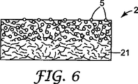
前述したように、本発明の触媒担体取付システムは、1枚のマットの形態、または複合マットの形態で使用することができる。図6は、1枚のマットの形態の触媒担体取付システム2の例を示す断面図である。この触媒担体取付システム2は、図5に関して前述した触媒担体取付システム2と同じ構造を有することができる。言い換えると、この触媒担体取付システム2は、無機繊維21を含むことができ、微粒子5が一方の表面(触媒担体と接触する表面)のある領域上に集中し、その一部がその表面上に露出する状態で研磨材料微粒子5を含むことができる。
As described above, the catalyst carrier mounting system of the present invention can be used in the form of a single mat or a composite mat. FIG. 6 is a cross-sectional view showing an example of the catalyst
本発明の触媒担体取付システムが複合マットの形態で使用される場合、種々の複合形態を取ることができる。しかし一般に、複合マットは、1枚の研磨剤含有マットと、研磨剤含有マットの繊維材料と同じまたは異なる繊維材料で形成された少なくとも1枚の補助マットとを使用して構成することができる。補助マットの繊維材料は、好ましくは前述の無機繊維である。基本的に、補助マットは、前述の研磨材料の粒子を含まない。性質の観点から、補助マットは、いわゆる「非発泡性または非膨張性のマット」であってよいし、非発泡性マットといわゆる「熱発泡性または膨張性のマット」との組み合わせを含むこともできる。 When the catalyst carrier mounting system of the present invention is used in the form of a composite mat, various composite forms can be taken. In general, however, a composite mat can be constructed using a single abrasive-containing mat and at least one auxiliary mat formed of a fiber material that is the same as or different from the fiber material of the abrasive-containing mat. The fiber material of the auxiliary mat is preferably the aforementioned inorganic fiber. Basically, the auxiliary mat does not contain particles of the aforementioned abrasive material. From the viewpoint of properties, the auxiliary mat may be a so-called “non-foamable or non-expandable mat”, or may include a combination of a non-foamable mat and a so-called “thermally foamable or expandable mat”. it can.
図7〜図9は、本発明の実施に好適な複合マットの例をそれぞれ示す断面図である。 7 to 9 are cross-sectional views showing examples of composite mats suitable for carrying out the present invention.
図7は、本発明の研磨剤含有マット21と非発泡性マットの補助マットとが一体的に組み合わされて、複合マットの形態を有する触媒担体取付システム2を形成している例を示している。図示される触媒担体取付システム2において、研磨剤含有マット21は、無機繊維、研磨材料の微粒子、および有機バインダーから形成される。一方、非発泡性マット22は、無機繊維および有機バインダーから形成される。研磨剤含有マット21および非発泡性マット22を形成するためには、同じまたは異なる無機繊維を使用することができる。たとえば、高耐熱性を有するアルミナ繊維を研磨剤含有マット21の形成に使用し、アルミナシリカ繊維またはガラス繊維を非発泡性マット22の形成に使用することができる。あるいは、アルミナシリカ繊維を研磨剤含有マット21の形成に使用し、ガラス繊維を非発泡性マット22の形成に使用することもできる。
FIG. 7 shows an example in which the abrasive-containing
本発明の触媒担体取付システムが湿式法で製造される場合、従来では無機繊維と有機バインダーとを組み合わせて使用される。しかし、本発明の実施においては、有機バインダーの種類およびその使用量は特に限定されないが、従来通り使用することができる。たとえば、ラテックスの形態で提供されるアクリル樹脂、スチレン−ブタジエン樹脂、アクリロニトリル樹脂、ポリウレタン樹脂、天然ゴム、ポリ酢酸ビニル樹脂などを有機バインダーとして使用することができる。このような有機バインダーは、不飽和ポリエステル樹脂、エポキシ樹脂、ポリビニルエステル樹脂などの可撓性熱可塑性樹脂を含むことができる。 When the catalyst carrier mounting system of the present invention is manufactured by a wet method, conventionally, inorganic fibers and organic binders are used in combination. However, in the practice of the present invention, the type of organic binder and the amount used thereof are not particularly limited, but can be used as usual. For example, an acrylic resin, a styrene-butadiene resin, an acrylonitrile resin, a polyurethane resin, a natural rubber, a polyvinyl acetate resin, or the like provided in the form of latex can be used as the organic binder. Such an organic binder can include a flexible thermoplastic resin such as an unsaturated polyester resin, an epoxy resin, or a polyvinyl ester resin.
図8は、複合マットの形態を有する触媒担体取付システム2が、本発明の研磨剤含有マット21を熱発泡性または膨張性マットの補助マット23と一体的に組み合わせることによって形成される例である。図示される触媒担体取付システム2において、研磨剤含有マット21は、無機繊維、研磨材料の微粒子、および有機バインダーから形成され、熱発泡性マット23は、無機繊維、有機バインダー、ならびに熱発泡性または膨張性材料から形成される。研磨剤含有マット21および熱発泡性マット23を形成するためには、同じまたは異なる無機繊維を使用することができる。たとえば、必要であれば高耐熱性を有するアルミナシリカ繊維またはアルミナ繊維を研磨剤含有マット21の形成に使用することができ、アルミナシリカ繊維またはガラス繊維を熱発泡性マット23の形成に使用することができる。たとえば、未発泡バーミキュライトまたは膨張黒鉛を、熱発泡性マット23の形成のための熱発泡性材料として使用することができる。
FIG. 8 is an example in which the catalyst
図9は、3層複合マットの形態を有する触媒担体取付システムが、本発明の研磨剤含有マット21を、非発泡性マットの第1の補助マット22、および熱発泡性マットの第2の補助マット23と一体的に組み合わせることによって製造される例を示している。図示される触媒担体取付システム2において、研磨剤含有マット21は、無機繊維、研磨材料の微粒子、および有機バインダーから形成される。一方、非発泡性マット22は、無機繊維および有機バインダーから形成され、熱発泡性マット23は、無機繊維、有機バインダー、および熱発泡性材料から形成される。研磨剤含有マット21、非発泡性マット22、および熱発泡性マット23は、それぞれ前述の方法で形成することができる。この例においては、研磨剤含有マット21および非発泡性マット22の両方は、好ましくは高耐熱性を有するアルミナ繊維から形成される。一方、熱発泡性マット23は、アルミナ繊維、ガラス繊維などを、未発泡バーミキュライトまたは膨張黒鉛などの熱発泡性材料と併用して形成することができる。
FIG. 9 shows a catalyst carrier mounting system in the form of a three-layer composite mat, in which the abrasive-containing
なお、摩擦力の改善に関して以下の機構が本発明の取付システムにおいて作用すると考えられるが、以下の説明は、本発明の触媒担体取付システムの作用を限定するものではない。 Although the following mechanism is considered to work in the mounting system of the present invention with respect to the improvement of the frictional force, the following description does not limit the operation of the catalyst carrier mounting system of the present invention.
本発明の取付システムの保持性能は、前述したように、取付システムの圧縮によって発生した圧力と、汚染制御要素と取付システムとの間の静止摩擦係数との積である「保持力」によって表すことができる。ここで、従来一般に使用されてきた取付システムは、無機繊維および有機バインダーから形成され、圧縮による圧力を発生させながら、繊維の損傷を抑制するように、無機繊維の間の隙間または空間が十分に確保される。本発明の発明者が行った観察によると、無機繊維の間のこれらの隙間または空間は、触媒担体と触媒担体取付システムとの間の接触領域を減少させ、これによって触媒担体と触媒担体取付システムとの間の摩擦係数が実質的に限定される。 As described above, the holding performance of the mounting system of the present invention is expressed by the “holding force” which is the product of the pressure generated by the compression of the mounting system and the coefficient of static friction between the pollution control element and the mounting system. Can do. Here, a mounting system that has been generally used in the past is formed from inorganic fibers and an organic binder, and there is sufficient gaps or spaces between the inorganic fibers to suppress damage to the fibers while generating pressure due to compression. Secured. According to observations made by the inventor of the present invention, these gaps or spaces between the inorganic fibers reduce the contact area between the catalyst support and the catalyst support mounting system, and thereby the catalyst support and the catalyst support mounting system. The coefficient of friction between is substantially limited.
本発明者は、耐熱性を有する無機粒子が、汚染制御装置と接触する取付システムの側面上または表面上に、好ましくは所定の厚さを有する部分で、配列され、好ましくはその場に接合されると、汚染制御要素と取付システムとの間の接触領域を増加させることができ、さらに汚染制御要素と取付システムとの間の摩擦係数を改善可能であることを発見した。特に、有機バインダーによって取付システムに固定された無機粒子は、特に有機バインダーが燃焼した後で、汚染制御要素と接触する繊維の間の隙間または空間内に移行することができる。汚染制御装置中に取り付けられるとき取付システムに作用する高い圧力によって、これらの空間にこれらの粒子が少なくとも移行しやすくなると考えられる。言い換えると、取付システムによって作用する圧力によって、粒子をこれらの空間内に効率的に押し込むことができると考えられる。取付システムと汚染制御要素との間の空間を充填することによって、粒子が、取付システムと汚染制御要素との間の接触領域を増加させる。あるいは、またはこれに加えて、希望するなら、これと同じ技術を適用して、取付システムと、汚染制御装置のケーシングまたはハウジングとの間の接触領域を増加させることもできる。粒子が、空間内に移行した状態などの平衡状態に到達すると、取付システムによって作用する圧力が、粒子のさらなる移動、特に取付システムの外への移動を防止、または少なくとも抑制する傾向にある。 The inventor has arranged that the heat-resistant inorganic particles are arranged on the side or surface of the mounting system in contact with the pollution control device, preferably in a part having a predetermined thickness, and preferably joined in situ. It has now been found that the contact area between the pollution control element and the mounting system can be increased and that the coefficient of friction between the pollution control element and the mounting system can be improved. In particular, the inorganic particles secured to the mounting system by the organic binder can migrate into the gaps or spaces between the fibers in contact with the pollution control element, particularly after the organic binder has burned. It is believed that the high pressure acting on the mounting system when installed in a pollution control device will at least facilitate the migration of these particles into these spaces. In other words, it is believed that the pressure exerted by the mounting system can effectively push the particles into these spaces. By filling the space between the mounting system and the pollution control element, the particles increase the contact area between the mounting system and the pollution control element. Alternatively, or in addition, if desired, the same technique can be applied to increase the contact area between the mounting system and the casing or housing of the pollution control device. When the particles reach an equilibrium state, such as moving into space, the pressure exerted by the mounting system tends to prevent or at least inhibit further movement of the particles, particularly movement out of the mounting system.
本発明による取付システムは、製紙に使用されたり、あるいは2003年11月17日に出願された国際公開第2004061279号パンフレット、および1997年2月7日に出願された米国特許第6,051,193号明細書(これらの記載内容全体が本明細書に援用される)に記載されるような湿式積層法によって一般に製造することができる。一般に、出発物質としての無機繊維および有機バインダーを任意の添加剤と混合した後、無機繊維の開繊、スラリーの調製、製紙による成形、および型の加圧などの工程段階を連続して行うことで、意図する取付システムが得られる。取付システムの構造に依存して、湿式方法と乾式方法との併用によって、または湿式方法の代わりに乾式方法を使用することによって取付システムを製造することもできる。乾式方法は、周知の従来方法によって行うことができ、典型的にはニードルパンチを使用する乾式方法である。 The mounting system according to the present invention is used in papermaking or published in WO 2004061279 filed on November 17, 2003 and US Pat. No. 6,051,193 filed on February 7, 1997. Can generally be produced by a wet lamination process as described in the specification (the entire contents of which are incorporated herein). In general, after mixing inorganic fibers and organic binders as starting materials with optional additives, the process steps such as opening of inorganic fibers, preparation of slurry, molding by papermaking, and pressurization of the mold are continuously performed. Thus, the intended mounting system can be obtained. Depending on the structure of the mounting system, the mounting system can also be manufactured by a combination of wet and dry methods, or by using a dry method instead of a wet method. The dry method can be performed by a well-known conventional method, and is typically a dry method using a needle punch.
より具体的に説明を行う。研磨粒子を含有するマットと、研磨粒子を含有しない補助マットとを含む複合マット形態の触媒担体取付システムは、たとえば以下の方法によって製造することができる。 A more specific description will be given. A catalyst carrier mounting system in the form of a composite mat including a mat containing abrasive particles and an auxiliary mat not containing abrasive particles can be produced, for example, by the following method.
製造方法A:
無機繊維および有機バインダーとを含有する第1のスラリー、ならびに無機繊維、研磨材料の微粒子、および有機バインダーを含有する第2のスラリーを調製する。通常の製紙方法によって第1のスラリーから補助マットの前駆体を形成し、従来の製紙方法によって第2のスラリーから研磨剤含有マットの前駆体を同様に形成する。次に、これら2つの前駆体の積層体を、1組の加圧ローラーの間に案内して圧縮することで、高密度にする。最後に、加圧した後の積層体を、1組の加熱ローラーの間で加熱し、乾燥させることで、2層一体型マット状触媒担体取付システムが得られる。
Production method A :
A first slurry containing inorganic fibers and an organic binder, and a second slurry containing inorganic fibers, fine particles of an abrasive material, and an organic binder are prepared. The auxiliary mat precursor is formed from the first slurry by a normal papermaking method, and the abrasive-containing mat precursor is similarly formed from the second slurry by a conventional papermaking method. Next, the laminated body of these two precursors is guided and compressed between a pair of pressure rollers to make it high density. Finally, the laminated body after pressurization is heated between a pair of heating rollers and dried to obtain a two-layer integrated mat-like catalyst carrier mounting system.
製造方法B:
無機繊維および有機バインダーとを含有する第1のスラリーを調製し、通常の製紙方法によって第1のスラリーから補助マットの前駆体を形成する。無機繊維、研磨材料の微粒子、および有機バインダーを含有する第2のスラリーを調製し、従来の製紙方法によって第2のスラリーから研磨剤含有マットの前駆体を同様に形成する。次に、得られた2つの前駆体を、通常の接着剤、樹脂、または両面テープなどの任意の接合手段、あるいはステープラーまたはスティッチングなどの機械的固定手段によって接合して一体化することで、2層一体型マット状触媒担体取付システムが得られる。
Production method B :
A first slurry containing inorganic fibers and an organic binder is prepared, and an auxiliary mat precursor is formed from the first slurry by a normal papermaking method. A second slurry containing inorganic fibers, abrasive fine particles, and an organic binder is prepared, and an abrasive-containing mat precursor is similarly formed from the second slurry by a conventional papermaking method. Next, the obtained two precursors are joined and integrated by any joining means such as ordinary adhesive, resin, or double-sided tape, or mechanical fixing means such as stapler or stitching, A two-layer integrated mat-like catalyst carrier mounting system is obtained.
製造方法C:
無機塩法を使用してアルミナ繊維前駆体ゾルゲルを調製し、紡糸した後、積層、ニードルパンチング、および所定の温度における焼き付けを行う。次に、有機バインダー中に研磨材料の微粒子を分散させることによって調製したスラリーを、得られたアルミナ繊維ブランケットの表面上に適用し、吸引によって脱水する。こうして、アルミナ繊維ブランケットの表面上に研磨材料の微粒子が選択的に分散し固定された、マット状触媒担体取付システムが得られる。
Production method C :
An alumina fiber precursor sol-gel is prepared using an inorganic salt method, spun, and then laminated, needle punched, and baked at a predetermined temperature. Next, a slurry prepared by dispersing fine particles of an abrasive material in an organic binder is applied onto the surface of the obtained alumina fiber blanket and dehydrated by suction. Thus, a mat-like catalyst carrier mounting system is obtained in which the fine particles of the abrasive material are selectively dispersed and fixed on the surface of the alumina fiber blanket.
製造方法D:
無機塩法を使用してアルミナ繊維前駆体ゾルゲルを調製し、紡糸した後、積層、ニードルパンチング、および所定の温度における焼き付けを行う。次に、無機繊維と、研磨材料の微粒子と、有機バインダーとからなるスラリーを、得られたアルミナ繊維ブランケットの表面上に適用し、吸引によって脱水する。
Production method D :
An alumina fiber precursor sol-gel is prepared using an inorganic salt method, spun, and then laminated, needle punched, and baked at a predetermined temperature. Next, a slurry composed of inorganic fibers, fine particles of an abrasive material, and an organic binder is applied onto the surface of the obtained alumina fiber blanket and dehydrated by suction.
次に、本発明の実施例を参照しながら本発明を説明する。なお、当然のことながら、本発明がこれらの実施例によって限定されるものではない。 The present invention will now be described with reference to examples of the present invention. As a matter of course, the present invention is not limited to these examples.
72重量%のアルミナと28重量%のシリカとからなるアルミナシリカ繊維(三菱化学産資(Mitsubishi Kagaku Sanshi)の製品)を最初に調製し、88重量%のこの繊維と、12重量%のアクリル型ラテックス(「ニッポール(Nippol)LX−816」、日本ゼオン株式会社(Nippon Zeon K.K.)の製品)とを混合して第1のスラリーを得た。このスラリーを調製するときは、固体濃度が5重量%となるように含水率を調整した。次に、この第1のスラリーを脱水し、メッシュ上でシートに成形し、シート状成形品を得た。次に加圧ローラーを使用してこの成形品を圧縮して高密度にした。次に、得られた高密度成形品を、加熱ローラーの使用によって130℃で20分間乾燥させて、非発泡性マットを得た。この非発泡性マットの平均表面密度は約1,200g/m2であった。ついでながら、以下の評価試験において本発明の複合マットと比較するための対照サンプルとしてもこの非発泡性マットを使用した。 Alumina-silica fiber (product of Mitsubishi Kagaku Sanshi) consisting of 72% by weight alumina and 28% by weight silica was first prepared, 88% by weight of this fiber and 12% by weight of acrylic type Latex ("Nippol LX-816", a product of Nippon Zeon K.K.) was mixed to obtain a first slurry. When preparing this slurry, the water content was adjusted so that the solid concentration was 5% by weight. Next, this first slurry was dehydrated and formed into a sheet on a mesh to obtain a sheet-like molded product. The molded product was then compressed to a high density using a pressure roller. Next, the obtained high-density molded article was dried at 130 ° C. for 20 minutes by using a heating roller to obtain a non-foamable mat. The average surface density of this non-foamable mat was about 1,200 g / m 2 . Incidentally, this non-foaming mat was also used as a control sample for comparison with the composite mat of the present invention in the following evaluation tests.
以下の表1に示す研磨材料の微粒子(ここでは「研磨粒子」と記載する)を、種々の粒度または粒径および添加量で、72重量%のアルミナと28重量%のシリカとからなる88重量%のアルミナシリカ繊維(サフィル・カンパニー(Saffil Co.))の製品)と、および12重量%のアクリル型ラテックス(「ニッポール(Nippol)LX−816」、日本ゼオン株式会社(Nippon Zeon K.K.)の製品)との混合物にブレンドすることで、第2のスラリーを得た。
アルミナ研磨剤:「タイプSA−J01」(昭和電工(Showa Denko)の製品)
炭化ケイ素研磨剤:タイプ「C」(昭和電工(Showa Denko)の製品)
ジルコニア研磨剤:タイプ「RZ−8C」(昭和電工(Showa Denko)の製品)
チタニア研磨剤:タイプ「R5N」(堺化学工業(Sakai Kagaku Kogyo)の製品)
88 wt.% Of 72 wt.% Alumina and 28 wt.% Silica in various particle sizes or particle sizes and loadings in the fine particles of the abrasive material shown in Table 1 below (referred to herein as “abrasive particles”). % Alumina silica fiber (a product of Saffil Co.), and 12% by weight acrylic latex ("Nippol LX-816", Nippon Zeon K.K. ) To obtain a second slurry.
Alumina abrasive: "Type SA-J01" (Showa Denko product)
Silicon carbide abrasive: Type “C” (Showa Denko product)
Zirconia abrasive: Type “RZ-8C” (Showa Denko product)
Titania abrasive: Type “R5N” (product of Sakai Kagaku Kogyo)
第2のスラリーを調製するときは、固体濃度が5重量%となるように含水率を調整した。次に、この第2のスラリーを脱水し、メッシュ上でシートに成形し、シート状成形品を得た。次に加圧ローラーを使用してこの成形品を圧縮して高密度にした。次に、得られた高密度成形品を、加熱ローラーの使用によって130℃で20分間乾燥させて、研磨剤含有マットを得た。この研磨剤含有マットの平均表面密度は約200g/m2であった。 When preparing the second slurry, the water content was adjusted so that the solid concentration was 5% by weight. Next, this second slurry was dehydrated and formed into a sheet on a mesh to obtain a sheet-like molded product. The molded product was then compressed to a high density using a pressure roller. Next, the obtained high-density molded article was dried at 130 ° C. for 20 minutes by using a heating roller to obtain an abrasive-containing mat. The average surface density of the abrasive-containing mat was about 200 g / m 2 .
続いて、上記方法で作製した非発泡性マットおよび研磨剤含有マットを積層し、アクリル接着剤を使用して接合させた。こうして、それぞれが長さ260mm、幅90mm、および厚さ12.5mmを有する積層一体型複合マットを得た。これらの複合マットを「サンプル1〜17」と呼んだ。 Subsequently, the non-foamable mat and the abrasive-containing mat produced by the above method were laminated and bonded using an acrylic adhesive. Thus, laminated integrated composite mats each having a length of 260 mm, a width of 90 mm, and a thickness of 12.5 mm were obtained. These composite mats were called “Samples 1-17”.
評価試験(摩擦力の測定):
触媒コンバータで使用されるときの触媒担体としての摩擦係数を測定するために、サンプル1〜17および対照試料の触媒担体取付システム(マット)のそれぞれの摩擦力を株式会社島津製作所(Shimazu Seisakusho K.K.)の製品である自動記録器「AGS100D」の使用によって以下のように測定した。
Evaluation test (measurement of frictional force) :
In order to measure the coefficient of friction as a catalyst carrier when used in a catalytic converter, the friction force of each of
長さ50mm、幅25mm、および厚さ12.5mmを有する試験片に各サンプルを切断した。次に、図10に示すように、触媒担体(この場合は、日本硝子(Nippon Glass Co.)のモノリス体)との接触面とは反対側の試験片2の表面を、両面テープでSUSシート(ステンレス鋼シート)46に接合させた。
Each sample was cut into a test piece having a length of 50 mm, a width of 25 mm, and a thickness of 12.5 mm. Next, as shown in FIG. 10, the surface of the
次に、長さ約1mのステンレス鋼コード43を準備し、そのコードの一端をSUSシート46に取り付けた。ロードセル44のすぐしたに滑車45を配置し、ロードセル44を上昇させたときに試験片2に取り付けたSUSシート46が地面に対して平行に移動するように、ステンレス鋼コードの43他方の端をロードセル44に取り付けた。
Next, a
次に、触媒担体41の中心軸が滑車45の進行方向に向かい、地面に対して平行となるように、触媒担体41上に試験片2を置いた。滑車45から最も離れた位置に試験片2が位置するように、ロードセル44の高さを調整した。
Next, the
49Nの加重47をSUSシート46上に取り付けた後、ロードセル44を上昇させ、矢印で示す方向にステンレス鋼コード43を100mm/分の引張速度で引っ張った。試験片2が触媒担体41の表面から滑り始める直前における荷重を静止摩擦力(kgf)として記録した。この値を、SUSシート46を含めた試験片2への荷重で割ることによって、静止摩擦係数を計算した。測定結果はすべて以下の表1に示した。
After attaching a

表1にまとめた測定結果から分かるように、本発明による触媒担体取付システムの表面(この実施例では複合マット)に加えることによって、触媒担体に対する摩擦係数を13%改善することができ、触媒担体取付システムの信頼性を改善することができた。 As can be seen from the measurement results summarized in Table 1, by adding to the surface of the catalyst carrier mounting system according to the present invention (in this embodiment, a composite mat), the coefficient of friction against the catalyst carrier can be improved by 13%. The reliability of the mounting system could be improved.
汚染制御装置(たとえば触媒コンバータ)の製造:
前述の評価試験において優れていると評価されたサンプルに関して、製造に使用した各複合マットを、外径78mmおよび長さ100mmおよびを有する日本ガイシ株式会社(Nippon Gaishi K.K.)の製品である汚染制御要素または本体(たとえば、モノリス触媒担体)の外周に巻き付け、別々に作製した。次に、ガイドコーンを使用して、複合マットが巻き付けられた触媒担体を、内径84mmおよび長さ120mmを有する円筒形のステンレス鋼ケーシングに40mm/秒の速度で押し込んだ。このキャンニング工程中の、触媒担体とケーシングとの間の間隙は約3mmであった。触媒担体および/または複合マットの破壊およびその他の損傷、ならびに触媒コンバータの組立性能の低下などの問題を引き起こさずに、意図する触媒コンバータを製造することができた。さらに、その結果得られた触媒コンバータは、実際の使用においてその意図する排気ガス精製作用を十分に示すことができた。
Production of pollution control devices (eg catalytic converters) :
Regarding the samples evaluated as being excellent in the above-described evaluation test, each composite mat used for production is a product of Nippon Gaishi KK having an outer diameter of 78 mm and a length of 100 mm. Wound around the periphery of a pollution control element or body (eg, monolith catalyst support) and made separately. Next, using a guide cone, the catalyst support on which the composite mat was wound was pushed into a cylindrical stainless steel casing having an inner diameter of 84 mm and a length of 120 mm at a speed of 40 mm / second. During this canning process, the gap between the catalyst support and the casing was about 3 mm. The intended catalytic converter could be manufactured without causing problems such as destruction of the catalyst support and / or composite mat and other damage, and degradation of the assembly performance of the catalytic converter. Furthermore, the catalytic converter obtained as a result could sufficiently exhibit its intended exhaust gas purification action in actual use.
本発明の一般的原理の上記開示および上述の詳細な説明から、当業者には、本発明が許容する種々の修正、再配置、および置換を容易に理解できるだろう。たとえば、本発明による取付システムは、高摩擦層またはコーティングを両面上に有するベースマットを含むことができる。ある高摩擦層は、研磨粒子を含浸させたセラミック繊維(たとえば、耐火性セラミック繊維)を含むことができ、たとえば、2003年11月17日に出願された国際公開第2004061279号パンフレット、および1997年2月7日に出願された米国特許第6,051,193号明細書に開示される方法と類似の湿式積層方法を使用してマットと同時成形することができる。他の高摩擦層は、マット上にロールコーティングされたシリカゾル(コロイダルシリカ)相を含むことができる。したがって、本発明の範囲は、特許請求の範囲およびそれらの等価物によってのみ限定されるべきである。 From the above disclosure of the general principles of the invention and the above detailed description, various modifications, rearrangements, and substitutions permitted by the invention will be readily apparent to those skilled in the art. For example, a mounting system according to the present invention can include a base mat having a high friction layer or coating on both sides. Some high friction layers can include ceramic fibers impregnated with abrasive particles (eg, refractory ceramic fibers), for example, WO 2004061279 filed Nov. 17, 2003, and 1997. It can be co-molded with a mat using a wet lamination method similar to that disclosed in US Pat. No. 6,051,193, filed Feb. 7. Other high friction layers can include a silica sol (colloidal silica) phase roll coated onto the mat. Accordingly, the scope of the invention should be limited only by the claims and their equivalents.
Claims (8)
汚染制御装置で使用するのに好適な繊維材料を含み、厚さを有するマットと、
前記取付システムが前記汚染制御装置で使用された場合に、前記汚染制御要素の外周面と接触するように、前記マットの接触面に配置された無機の微粒子と
を含み、
前記微粒子は、耐熱性を有し、JIS R6001によって規定される研磨剤粒度に関してF1,200〜F60の範囲内の粒度を有し、かつ前記マットの接触面と前記汚染制御要素の外周面との間の摩擦係数を増加させることができ、そして
前記微粒子が、前記マット中に含まれる全内容物の少なくとも70%の含有量で、前記マットの前記接触面から、前記マットをその厚さ方向で観察した場合に50%の深さまでの範囲の下部領域に含まれる、取付システム。 A mounting system suitable for mounting a pollution control element inside a pollution control device,
A mat comprising a fibrous material suitable for use in a pollution control device and having a thickness;
Inorganic fine particles disposed on the mating surface of the mat so as to come into contact with the outer circumferential surface of the pollution control element when the mounting system is used in the pollution control device;
Including
The fine particles have heat resistance, have a particle size in the range of F1,200 to F60 with respect to the abrasive particle size defined by JIS R6001, and the contact surface of the mat and the outer peripheral surface of the contamination control element. The coefficient of friction between the mat and the fine particles in a thickness direction from the contact surface of the mat with a content of at least 70% of the total content contained in the mat. contained in the lower region of the range of up to 50% of the depth when observed, the system INSTALLATION.
汚染制御装置で使用するのに好適な繊維材料を含み、厚さを有するマットと、
前記取付システムが前記汚染制御装置で使用された場合に、前記汚染制御要素の外周面と接触するように、前記マットの接触面に配置された無機の微粒子と
を含み、
前記微粒子は、耐熱性を有し、JIS R6001によって規定される研磨剤粒度に関してF1,200〜F60の範囲内の粒度を有し、かつ前記マットの接触面と前記汚染制御要素の外周面との間の摩擦係数を増加させることができ、そして
前記マットをその厚さ方向で観察した場合に、前記微粒子が、前記マットの前記接触面に向かって濃度が増加するように分散している、取付システム。 A mounting system suitable for mounting a pollution control element inside a pollution control device,
A mat comprising a fibrous material suitable for use in a pollution control device and having a thickness;
Inorganic fine particles disposed on the mating surface of the mat so as to come into contact with the outer circumferential surface of the pollution control element when the mounting system is used in the pollution control device;
Including
The fine particles have heat resistance, have a particle size in the range of F1,200 to F60 with respect to the abrasive particle size defined by JIS R6001, and the contact surface of the mat and the outer peripheral surface of the contamination control element. friction coefficient between can be increased, and the mat when viewed in the thickness direction, the fine particles, the concentration towards the contact surface of said mat is dispersed so as to increase the attachment system.
Applications Claiming Priority (3)
| Application Number | Priority Date | Filing Date | Title |
|---|---|---|---|
| US58819604P | 2004-07-15 | 2004-07-15 | |
| US60/588,196 | 2004-07-15 | ||
| PCT/US2005/025206 WO2006020058A1 (en) | 2004-07-15 | 2005-07-15 | Pollution control element mounting system and pollution control device |
Related Child Applications (1)
| Application Number | Title | Priority Date | Filing Date |
|---|---|---|---|
| JP2012154742A Division JP5357311B2 (en) | 2004-07-15 | 2012-07-10 | Contamination control element mounting system and contamination control device |
Publications (3)
| Publication Number | Publication Date |
|---|---|
| JP2008506886A JP2008506886A (en) | 2008-03-06 |
| JP2008506886A5 JP2008506886A5 (en) | 2008-09-18 |
| JP5133685B2 true JP5133685B2 (en) | 2013-01-30 |
Family
ID=35149028
Family Applications (2)
| Application Number | Title | Priority Date | Filing Date |
|---|---|---|---|
| JP2007521689A Expired - Fee Related JP5133685B2 (en) | 2004-07-15 | 2005-07-15 | Contamination control element mounting system and contamination control device |
| JP2012154742A Active JP5357311B2 (en) | 2004-07-15 | 2012-07-10 | Contamination control element mounting system and contamination control device |
Family Applications After (1)
| Application Number | Title | Priority Date | Filing Date |
|---|---|---|---|
| JP2012154742A Active JP5357311B2 (en) | 2004-07-15 | 2012-07-10 | Contamination control element mounting system and contamination control device |
Country Status (11)
| Country | Link |
|---|---|
| US (1) | US7858051B2 (en) |
| EP (1) | EP1784560B1 (en) |
| JP (2) | JP5133685B2 (en) |
| KR (2) | KR101397742B1 (en) |
| CN (1) | CN100478547C (en) |
| AT (1) | ATE494463T1 (en) |
| BR (1) | BRPI0513381B1 (en) |
| CA (1) | CA2573804A1 (en) |
| DE (1) | DE602005025777D1 (en) |
| WO (1) | WO2006020058A1 (en) |
| ZA (1) | ZA200701328B (en) |
Families Citing this family (39)
| Publication number | Priority date | Publication date | Assignee | Title |
|---|---|---|---|---|
| KR101397742B1 (en) | 2004-07-15 | 2014-05-20 | 쓰리엠 이노베이티브 프로퍼티즈 컴파니 | Pollution control element mounting system and pollution control device |
| JP4802048B2 (en) | 2006-06-16 | 2011-10-26 | イビデン株式会社 | Holding sealing material, exhaust gas treatment apparatus, and manufacturing method thereof |
| JP2008045521A (en) * | 2006-08-21 | 2008-02-28 | Ibiden Co Ltd | Holding sealant and exhaust gas treatment device |
| JP2008051004A (en) * | 2006-08-24 | 2008-03-06 | Ibiden Co Ltd | Retention seal material and exhaust gas treatment device |
| JP4268182B2 (en) * | 2006-09-29 | 2009-05-27 | イビデン株式会社 | Exhaust gas treatment device and manufacturing method thereof |
| JP4863828B2 (en) * | 2006-09-29 | 2012-01-25 | イビデン株式会社 | Sheet material, method for manufacturing the same, and exhaust gas treatment apparatus |
| EP1953357B1 (en) * | 2007-01-26 | 2009-08-26 | Ibiden Co., Ltd. | Sheet member and manufacturing method thereof, exhaust gas treating apparatus and manufacturing method thereof, and silencing device |
| US8627853B1 (en) * | 2007-08-17 | 2014-01-14 | Unifrax I Llc | Insulating material for automotive exhaust line tubing and manifolds |
| JP5869220B2 (en) * | 2007-10-09 | 2016-02-24 | スリーエム イノベイティブ プロパティズ カンパニー | Mounting mat containing inorganic nanoparticles and method for producing the same |
| PL2212072T3 (en) | 2007-10-09 | 2014-01-31 | 3M Innovative Properties Co | Method of making mounting mats for mounting pollution control element |
| JP5183296B2 (en) * | 2008-05-15 | 2013-04-17 | イビデン株式会社 | Holding sealing material, manufacturing method of holding sealing material, and exhaust gas purification device |
| JP2011026755A (en) * | 2009-07-01 | 2011-02-10 | Ibiden Co Ltd | Mat material and exhaust gas treatment apparatus |
| PL2655817T3 (en) | 2010-12-22 | 2019-04-30 | 3M Innovative Properties Co | Mounting mat with lower friction surface for assembling and higher friction surface for mounting |
| US8424636B2 (en) * | 2011-04-29 | 2013-04-23 | E.I. Du Pont De Nemours And Company | Muffler assembly and process of manufacture |
| KR101291964B1 (en) * | 2011-11-16 | 2013-08-09 | 이비덴 가부시키가이샤 | Holding sealing material, method for manufacturing the same and exhaust gas purifying apparatus |
| JP5990393B2 (en) | 2012-04-03 | 2016-09-14 | イビデン株式会社 | Holding sealing material and exhaust gas purification device |
| JP2014092150A (en) * | 2012-11-07 | 2014-05-19 | Ibiden Co Ltd | Holding seal material, holding seal material manufacturing method and exhaust gas purification device |
| JP2014190191A (en) * | 2013-03-26 | 2014-10-06 | Ibiden Co Ltd | Holding seal material for exhaust gas purification device, method of manufacturing holding seal material, exhaust gas purification device, and method of manufacturing exhaust gas purification device |
| JP6218529B2 (en) * | 2013-09-24 | 2017-10-25 | イビデン株式会社 | Holding sealing material, manufacturing method of holding sealing material, manufacturing method of exhaust gas purification device, and exhaust gas purification device |
| US9963395B2 (en) | 2013-12-11 | 2018-05-08 | Baker Hughes, A Ge Company, Llc | Methods of making carbon composites |
| KR102421357B1 (en) * | 2013-12-19 | 2022-07-18 | 쓰리엠 이노베이티브 프로퍼티즈 컴파니 | Using recycled waste water to make nonwoven fibrous materials suitable for use in a pollution control device or in a firestop |
| JP6544890B2 (en) * | 2014-05-23 | 2019-07-17 | スリーエム イノベイティブ プロパティズ カンパニー | Method of manufacturing holding material for pollution control element |
| US9325012B1 (en) | 2014-09-17 | 2016-04-26 | Baker Hughes Incorporated | Carbon composites |
| US10315922B2 (en) | 2014-09-29 | 2019-06-11 | Baker Hughes, A Ge Company, Llc | Carbon composites and methods of manufacture |
| US10480288B2 (en) | 2014-10-15 | 2019-11-19 | Baker Hughes, A Ge Company, Llc | Articles containing carbon composites and methods of manufacture |
| US9962903B2 (en) | 2014-11-13 | 2018-05-08 | Baker Hughes, A Ge Company, Llc | Reinforced composites, methods of manufacture, and articles therefrom |
| US9745451B2 (en) * | 2014-11-17 | 2017-08-29 | Baker Hughes Incorporated | Swellable compositions, articles formed therefrom, and methods of manufacture thereof |
| US11097511B2 (en) | 2014-11-18 | 2021-08-24 | Baker Hughes, A Ge Company, Llc | Methods of forming polymer coatings on metallic substrates |
| US9714709B2 (en) | 2014-11-25 | 2017-07-25 | Baker Hughes Incorporated | Functionally graded articles and methods of manufacture |
| US10300627B2 (en) | 2014-11-25 | 2019-05-28 | Baker Hughes, A Ge Company, Llc | Method of forming a flexible carbon composite self-lubricating seal |
| JP6419556B2 (en) * | 2014-12-03 | 2018-11-07 | イビデン株式会社 | Holding sealing material and exhaust gas purification device |
| EP3034825B1 (en) * | 2014-12-18 | 2017-09-27 | 3M Innovative Properties Company | Mounting mat for an exhaust gas treatment device |
| KR20170118679A (en) * | 2015-02-24 | 2017-10-25 | 유니프랙스 아이 엘엘씨 | High temperature resistant insulation mat |
| US9840887B2 (en) | 2015-05-13 | 2017-12-12 | Baker Hughes Incorporated | Wear-resistant and self-lubricant bore receptacle packoff tool |
| US10125274B2 (en) | 2016-05-03 | 2018-11-13 | Baker Hughes, A Ge Company, Llc | Coatings containing carbon composite fillers and methods of manufacture |
| US10344559B2 (en) | 2016-05-26 | 2019-07-09 | Baker Hughes, A Ge Company, Llc | High temperature high pressure seal for downhole chemical injection applications |
| US20180134002A1 (en) * | 2016-11-16 | 2018-05-17 | Tex Tech Industries, Inc. | Woven, nonwoven, and expandable graphite composite material |
| JP7085819B2 (en) | 2017-10-31 | 2022-06-17 | スリーエム イノベイティブ プロパティズ カンパニー | Retaining material for exhaust gas treatment equipment, its manufacturing method and exhaust gas treatment equipment |
| JP2022131299A (en) * | 2021-02-26 | 2022-09-07 | 日本碍子株式会社 | Cylindrical member for exhaust gas treatment device, exhaust gas treatment device using cylindrical member, and insulation layer used in cylindrical member |
Family Cites Families (27)
| Publication number | Priority date | Publication date | Assignee | Title |
|---|---|---|---|---|
| US27747A (en) | 1860-04-03 | Joseph smith | ||
| US3444925A (en) | 1957-05-07 | 1969-05-20 | Minnesota Mining & Mfg | Structural articles and method of making |
| GB1051496A (en) | 1963-08-12 | |||
| US3441381A (en) | 1965-06-22 | 1969-04-29 | Engelhard Ind Inc | Apparatus for purifying exhaust gases of an internal combustion engine |
| JP2001259438A (en) | 2000-03-22 | 2001-09-25 | Ibiden Co Ltd | Catalytic converter |
| US3771967A (en) | 1971-12-14 | 1973-11-13 | Tenneco Inc | Catalytic reactor with monolithic element |
| US3798006A (en) | 1971-12-14 | 1974-03-19 | Tenneco Inc | Catalytic converter for exhuast gases |
| US3861881A (en) * | 1971-12-14 | 1975-01-21 | Tenneco Inc | Catalyst converter with monolithic element |
| JP2735973B2 (en) * | 1991-03-25 | 1998-04-02 | 日本碍子株式会社 | Method for manufacturing ceramic honeycomb structure |
| US5250269A (en) | 1992-05-21 | 1993-10-05 | Minnesota Mining And Manufacturing Company | Catalytic converter having a metallic monolith mounted by a heat-insulating mat of refractory ceramic fibers |
| US5955177A (en) | 1996-09-03 | 1999-09-21 | 3M Innovative Properties Company | Fire barrier mat |
| US6051193A (en) * | 1997-02-06 | 2000-04-18 | 3M Innovative Properties Company | Multilayer intumescent sheet |
| US6025455A (en) | 1997-05-26 | 2000-02-15 | Nissan Chemicals Industries, Ltd. | Process of producing hydrophobic organosilica sol |
| DE19803063A1 (en) | 1998-01-28 | 1999-07-29 | Eberspaecher J Gmbh & Co | Holding and insulating ceramic monoliths in vehicle exhaust gas unit |
| JP3949265B2 (en) * | 1998-03-30 | 2007-07-25 | 日本碍子株式会社 | Method for incorporating ceramic honeycomb structure and holding member used in the method |
| JP3660142B2 (en) * | 1998-11-02 | 2005-06-15 | 本田技研工業株式会社 | Holding mat for catalytic converter and method for manufacturing the same |
| JP2000206421A (en) | 1999-01-08 | 2000-07-28 | Olympus Optical Co Ltd | Binoculars |
| US20020127154A1 (en) * | 2000-03-03 | 2002-09-12 | Foster Michael R. | Exhaust control device and method for manufacture thereof |
| JP4042305B2 (en) | 2000-06-21 | 2008-02-06 | イビデン株式会社 | Holding seal material for exhaust gas purification catalytic converter |
| JP2002070545A (en) * | 2000-08-25 | 2002-03-08 | Ibiden Co Ltd | Storage structure for ceramic honeycomb structure |
| JP2002206421A (en) * | 2001-01-11 | 2002-07-26 | Ibiden Co Ltd | Holding-seal material for catalytic converter, ceramic fiber, and method of manufacturing the ceramic fiber |
| EP2034152A3 (en) | 2001-05-25 | 2012-10-03 | Ibiden Co., Ltd. | Alumina-silica based fiber, ceramic fiber aggregation, holding seal material and manufacturing methods thereof, as well as manufacturing method of alumina fiber aggregation |
| US20030129102A1 (en) | 2002-01-08 | 2003-07-10 | Turek Alan Gerard | Exhaust emissions control devices comprising adhesive |
| US7553888B2 (en) | 2002-10-14 | 2009-06-30 | Akzo Nobel N.V. | Aqueous dispersion |
| AR054074A1 (en) | 2004-06-29 | 2007-06-06 | Unifrax Corp | DEVICE FOR TREATMENT OF EXHAUST GASES AND METHOD TO PREPARE IT |
| KR101397742B1 (en) | 2004-07-15 | 2014-05-20 | 쓰리엠 이노베이티브 프로퍼티즈 컴파니 | Pollution control element mounting system and pollution control device |
| KR101497865B1 (en) | 2005-09-08 | 2015-03-04 | 쓰리엠 이노베이티브 프로퍼티즈 컴파니 | Holding material for pollution control element and pollution control apparatus |
-
2005
- 2005-07-15 KR KR1020137011145A patent/KR101397742B1/en active IP Right Grant
- 2005-07-15 KR KR1020077003520A patent/KR101299836B1/en active IP Right Grant
- 2005-07-15 JP JP2007521689A patent/JP5133685B2/en not_active Expired - Fee Related
- 2005-07-15 BR BRPI0513381-5A patent/BRPI0513381B1/en not_active IP Right Cessation
- 2005-07-15 WO PCT/US2005/025206 patent/WO2006020058A1/en active Application Filing
- 2005-07-15 DE DE602005025777T patent/DE602005025777D1/en active Active
- 2005-07-15 EP EP05778057A patent/EP1784560B1/en active Active
- 2005-07-15 CA CA002573804A patent/CA2573804A1/en not_active Abandoned
- 2005-07-15 US US11/572,075 patent/US7858051B2/en active Active
- 2005-07-15 CN CNB2005800311141A patent/CN100478547C/en active Active
- 2005-07-15 AT AT05778057T patent/ATE494463T1/en not_active IP Right Cessation
-
2007
- 2007-02-14 ZA ZA200701328A patent/ZA200701328B/en unknown
-
2012
- 2012-07-10 JP JP2012154742A patent/JP5357311B2/en active Active
Also Published As
| Publication number | Publication date |
|---|---|
| ZA200701328B (en) | 2008-08-27 |
| KR20070029290A (en) | 2007-03-13 |
| EP1784560A1 (en) | 2007-05-16 |
| EP1784560B1 (en) | 2011-01-05 |
| CN100478547C (en) | 2009-04-15 |
| KR101397742B1 (en) | 2014-05-20 |
| CA2573804A1 (en) | 2006-02-23 |
| ATE494463T1 (en) | 2011-01-15 |
| US20080175764A1 (en) | 2008-07-24 |
| BRPI0513381A (en) | 2008-05-06 |
| CN101023247A (en) | 2007-08-22 |
| WO2006020058A1 (en) | 2006-02-23 |
| KR20130051026A (en) | 2013-05-16 |
| DE602005025777D1 (en) | 2011-02-17 |
| JP2008506886A (en) | 2008-03-06 |
| US7858051B2 (en) | 2010-12-28 |
| KR101299836B1 (en) | 2013-08-23 |
| JP2012215179A (en) | 2012-11-08 |
| BRPI0513381B1 (en) | 2018-07-10 |
| JP5357311B2 (en) | 2013-12-04 |
Similar Documents
| Publication | Publication Date | Title |
|---|---|---|
| JP5133685B2 (en) | Contamination control element mounting system and contamination control device | |
| JP5275802B2 (en) | Retaining material for antifouling elements and antifouling devices | |
| KR101145019B1 (en) | Pollution Control Element-Retaining Member and Pollution Control Device | |
| CN101155978B (en) | Pollution control element-mounting member and pollution control device | |
| JP2023506889A (en) | Insulation structure and manufacturing method thereof | |
| JP2019081156A (en) | Holding material for contamination control element, method of manufacturing the same, and contamination control device |
Legal Events
| Date | Code | Title | Description |
|---|---|---|---|
| A521 | Request for written amendment filed |
Free format text: JAPANESE INTERMEDIATE CODE: A523 Effective date: 20080715 |
|
| A621 | Written request for application examination |
Free format text: JAPANESE INTERMEDIATE CODE: A621 Effective date: 20080715 |
|
| A977 | Report on retrieval |
Free format text: JAPANESE INTERMEDIATE CODE: A971007 Effective date: 20101129 |
|
| A131 | Notification of reasons for refusal |
Free format text: JAPANESE INTERMEDIATE CODE: A131 Effective date: 20101207 |
|
| A601 | Written request for extension of time |
Free format text: JAPANESE INTERMEDIATE CODE: A601 Effective date: 20110303 |
|
| A602 | Written permission of extension of time |
Free format text: JAPANESE INTERMEDIATE CODE: A602 Effective date: 20110310 |
|
| A521 | Request for written amendment filed |
Free format text: JAPANESE INTERMEDIATE CODE: A523 Effective date: 20110606 |
|
| A131 | Notification of reasons for refusal |
Free format text: JAPANESE INTERMEDIATE CODE: A131 Effective date: 20120110 |
|
| A601 | Written request for extension of time |
Free format text: JAPANESE INTERMEDIATE CODE: A601 Effective date: 20120410 |
|
| A602 | Written permission of extension of time |
Free format text: JAPANESE INTERMEDIATE CODE: A602 Effective date: 20120417 |
|
| A521 | Request for written amendment filed |
Free format text: JAPANESE INTERMEDIATE CODE: A523 Effective date: 20120710 |
|
| TRDD | Decision of grant or rejection written | ||
| A01 | Written decision to grant a patent or to grant a registration (utility model) |
Free format text: JAPANESE INTERMEDIATE CODE: A01 Effective date: 20121009 |
|
| A01 | Written decision to grant a patent or to grant a registration (utility model) |
Free format text: JAPANESE INTERMEDIATE CODE: A01 |
|
| A61 | First payment of annual fees (during grant procedure) |
Free format text: JAPANESE INTERMEDIATE CODE: A61 Effective date: 20121108 |
|
| FPAY | Renewal fee payment (event date is renewal date of database) |
Free format text: PAYMENT UNTIL: 20151116 Year of fee payment: 3 |
|
| R150 | Certificate of patent or registration of utility model |
Ref document number: 5133685 Country of ref document: JP Free format text: JAPANESE INTERMEDIATE CODE: R150 |
|
| R250 | Receipt of annual fees |
Free format text: JAPANESE INTERMEDIATE CODE: R250 |
|
| R250 | Receipt of annual fees |
Free format text: JAPANESE INTERMEDIATE CODE: R250 |
|
| R250 | Receipt of annual fees |
Free format text: JAPANESE INTERMEDIATE CODE: R250 |
|
| R250 | Receipt of annual fees |
Free format text: JAPANESE INTERMEDIATE CODE: R250 |
|
| R250 | Receipt of annual fees |
Free format text: JAPANESE INTERMEDIATE CODE: R250 |
|
| R250 | Receipt of annual fees |
Free format text: JAPANESE INTERMEDIATE CODE: R250 |
|
| LAPS | Cancellation because of no payment of annual fees |