JP5133354B2 - Electric circuit charging / shut-off device - Google Patents
Electric circuit charging / shut-off device Download PDFInfo
- Publication number
- JP5133354B2 JP5133354B2 JP2009545914A JP2009545914A JP5133354B2 JP 5133354 B2 JP5133354 B2 JP 5133354B2 JP 2009545914 A JP2009545914 A JP 2009545914A JP 2009545914 A JP2009545914 A JP 2009545914A JP 5133354 B2 JP5133354 B2 JP 5133354B2
- Authority
- JP
- Japan
- Prior art keywords
- microswitch
- explosive
- membrane
- magnetic field
- conductors
- Prior art date
- Legal status (The legal status is an assumption and is not a legal conclusion. Google has not performed a legal analysis and makes no representation as to the accuracy of the status listed.)
- Expired - Fee Related
Links
Images


Classifications
-
- H—ELECTRICITY
- H01—ELECTRIC ELEMENTS
- H01H—ELECTRIC SWITCHES; RELAYS; SELECTORS; EMERGENCY PROTECTIVE DEVICES
- H01H39/00—Switching devices actuated by an explosion produced within the device and initiated by an electric current
-
- H—ELECTRICITY
- H01—ELECTRIC ELEMENTS
- H01H—ELECTRIC SWITCHES; RELAYS; SELECTORS; EMERGENCY PROTECTIVE DEVICES
- H01H39/00—Switching devices actuated by an explosion produced within the device and initiated by an electric current
- H01H39/004—Closing switches
-
- H—ELECTRICITY
- H01—ELECTRIC ELEMENTS
- H01H—ELECTRIC SWITCHES; RELAYS; SELECTORS; EMERGENCY PROTECTIVE DEVICES
- H01H39/00—Switching devices actuated by an explosion produced within the device and initiated by an electric current
- H01H39/006—Opening by severing a conductor
-
- H—ELECTRICITY
- H01—ELECTRIC ELEMENTS
- H01H—ELECTRIC SWITCHES; RELAYS; SELECTORS; EMERGENCY PROTECTIVE DEVICES
- H01H50/00—Details of electromagnetic relays
- H01H50/005—Details of electromagnetic relays using micromechanics
-
- H—ELECTRICITY
- H01—ELECTRIC ELEMENTS
- H01H—ELECTRIC SWITCHES; RELAYS; SELECTORS; EMERGENCY PROTECTIVE DEVICES
- H01H36/00—Switches actuated by change of magnetic field or of electric field, e.g. by change of relative position of magnet and switch, by shielding
- H01H2036/0093—Micromechanical switches actuated by a change of the magnetic field
-
- H—ELECTRICITY
- H01—ELECTRIC ELEMENTS
- H01H—ELECTRIC SWITCHES; RELAYS; SELECTORS; EMERGENCY PROTECTIVE DEVICES
- H01H39/00—Switching devices actuated by an explosion produced within the device and initiated by an electric current
- H01H2039/008—Switching devices actuated by an explosion produced within the device and initiated by an electric current using the switch for a battery cutoff
-
- H—ELECTRICITY
- H01—ELECTRIC ELEMENTS
- H01H—ELECTRIC SWITCHES; RELAYS; SELECTORS; EMERGENCY PROTECTIVE DEVICES
- H01H50/00—Details of electromagnetic relays
- H01H50/005—Details of electromagnetic relays using micromechanics
- H01H2050/007—Relays of the polarised type, e.g. the MEMS relay beam having a preferential magnetisation direction
-
- H—ELECTRICITY
- H01—ELECTRIC ELEMENTS
- H01H—ELECTRIC SWITCHES; RELAYS; SELECTORS; EMERGENCY PROTECTIVE DEVICES
- H01H35/00—Switches operated by change of a physical condition
- H01H35/14—Switches operated by change of acceleration, e.g. by shock or vibration, inertia switch
-
- H—ELECTRICITY
- H01—ELECTRIC ELEMENTS
- H01H—ELECTRIC SWITCHES; RELAYS; SELECTORS; EMERGENCY PROTECTIVE DEVICES
- H01H35/00—Switches operated by change of a physical condition
- H01H35/14—Switches operated by change of acceleration, e.g. by shock or vibration, inertia switch
- H01H35/144—Switches operated by change of acceleration, e.g. by shock or vibration, inertia switch operated by vibration
-
- H—ELECTRICITY
- H01—ELECTRIC ELEMENTS
- H01H—ELECTRIC SWITCHES; RELAYS; SELECTORS; EMERGENCY PROTECTIVE DEVICES
- H01H35/00—Switches operated by change of a physical condition
- H01H35/24—Switches operated by change of fluid pressure, by fluid pressure waves, or by change of fluid flow
-
- H—ELECTRICITY
- H01—ELECTRIC ELEMENTS
- H01H—ELECTRIC SWITCHES; RELAYS; SELECTORS; EMERGENCY PROTECTIVE DEVICES
- H01H36/00—Switches actuated by change of magnetic field or of electric field, e.g. by change of relative position of magnet and switch, by shielding
-
- H—ELECTRICITY
- H01—ELECTRIC ELEMENTS
- H01H—ELECTRIC SWITCHES; RELAYS; SELECTORS; EMERGENCY PROTECTIVE DEVICES
- H01H59/00—Electrostatic relays; Electro-adhesion relays
- H01H59/0009—Electrostatic relays; Electro-adhesion relays making use of micromechanics
Landscapes
- Physics & Mathematics (AREA)
- Electromagnetism (AREA)
- Thermally Actuated Switches (AREA)
- Air Bags (AREA)
- Electromagnets (AREA)
- Switches That Are Operated By Magnetic Or Electric Fields (AREA)
- Electronic Switches (AREA)
- Micromachines (AREA)
- Electrical Discharge Machining, Electrochemical Machining, And Combined Machining (AREA)
- Oscillators With Electromechanical Resonators (AREA)
- Input Circuits Of Receivers And Coupling Of Receivers And Audio Equipment (AREA)
Abstract
Description
本発明は電気回路の投入/遮断装置に関する。この装置は、火薬(pyrotechnic charge)に基づいて動作する。 The present invention relates to an electrical circuit turning on / off device. This device operates on the basis of the gunpowder (pyrotechnic charge).
DE4406730号明細書などから電気回路の遮断装置が知られている。この装置は、火薬およびこの火薬の燃焼によって発生するガスの作用で並進動作するピストンを有する火薬アクチュエータなどを有する。このピストンは、二つの導電体間を最初に電気的に接続するコネクタブリッジに当接するフィンガーを有している。このブリッジはバネに取り付けられている。動作時は、火薬の燃焼によって発生するガスがピストンを移動させ、そのピストンがブリッジを押して、二つの導電体の接続を切断し、電気回路を遮断する。 An electrical circuit breaker is known from DE 4406730. The device has a like explosive actuator having a piston to translate by action of the gases generated by the combustion of gunpowder and the explosive. The piston has a finger that abuts a connector bridge that initially electrically connects the two conductors. This bridge is attached to a spring. In operation, the gas generated by the explosive combustion moves the piston, which pushes the bridge, disconnecting the two conductors and breaking the electrical circuit.
この従来技術の装置では、火薬の点火を制御するのに外部の検知装置を使用する必要があった。また、時間の経過によって消耗しがちな機械手段を主に使用するため、故障を引き起こすこともある。 In this prior art device, it was necessary to use an external sensing device to control the ignition of the explosive . In addition, since mechanical means that tend to be consumed over time are mainly used, a failure may occur.
本発明の目的は、時間の経過によって消耗することに敏感でなく、点火が装置内で直接的に制御される火薬によって動作する電気回路の投入/遮断装置を提供することにある。 It is an object of the present invention to provide an electrical circuit on / off device that is not sensitive to wear over time and that is operated by gunpowder whose ignition is controlled directly within the device.
この目的は、
− 電気回路の投入または遮断をそれぞれを行うために点火する火薬と、
− 前記火薬を点火する手段と、を有する電気回路の投入/遮断装置において、
− 前記点火手段は前記電気回路に接続され、
− 前記点火手段は火薬の点火を制御できる磁気作用を持ったマイクロスイッチを有することを特徴とする、電気回路の投入/遮断装置によって達成される。
This purpose is
- the explosive igniting to perform respectively on or interruption of the electric circuit,
A means for igniting said explosive , and a device for turning on / off an electric circuit comprising:
The ignition means is connected to the electrical circuit;
The ignition means is achieved by means of an electrical circuit turning on / off device, characterized in that it has a magnetic microswitch that can control the ignition of the gunpowder ;
一つの特徴によれば、前記マイクロスイッチは、一方が前記電気回路に、他方がアースに接続された回路の分岐に配置される。別の特徴によれば、前記点火手段は、マイクロスイッチと直列に設置され、火薬の点火が可能な抵抗加熱素子を有する。 According to one characteristic, the microswitch is arranged at a branch of the circuit, one connected to the electrical circuit and the other to ground. According to another characteristic, the ignition means has a resistance heating element that is installed in series with the microswitch and capable of igniting explosives .
第一変形例によれば、前記マイクロスイッチは、例えば並進動作することのできる可動永久磁石によって制御される。 According to a first variant, the microswitch is controlled by a movable permanent magnet which can be translated, for example.
第二変形例によれば、前記マイクロスイッチは、励起コイルによって制御される。 According to a second variant, the microswitch is controlled by an excitation coil.
第一構成では、前記励起コイルは前記電気回路に対して並列に設置される。従って、本発明の装置は、前記電気回路が二つの導電体および前記火薬の燃焼によって発生するガスの作用で移動でき、最初に前記二つの導電体を接続する接続部材を有する、電気回路の遮断装置である。 In the first configuration, the excitation coil is installed in parallel to the electric circuit. Accordingly, the apparatus of the present invention is an electrical circuit breaker, wherein the electrical circuit is movable under the action of two conductors and a gas generated by the combustion of the explosive , and has a connection member that first connects the two conductors. Device.
第二構成では、前記励起コイルは前記マイクロスイッチと並列に設置される。この場合、前記励起コイルは検知器によって制御される。従って、本発明の装置は、前記電気回路が二つの導電体および前記火薬の燃焼によって発生するガスの作用で移動できる接続部材を有する、電気回路の投入装置である。この投入装置において、前記接続部材は最初、前記二つの導電体と切断されており、例えば前記火薬を含む第一チャンバーと前記二つの導電体が通る第二チャンバーとを区切るピストンと一体化している。 In the second configuration, the excitation coil is installed in parallel with the microswitch. In this case, the excitation coil is controlled by a detector. Therefore, the apparatus of the present invention is an electric circuit charging device having a connecting member that can move by the action of gas generated by combustion of two conductors and the explosive . In this charging device, the connecting member is first cut from the two conductors, and is integrated with, for example, a piston that separates the first chamber containing the explosive and the second chamber through which the two conductors pass. .
本発明によれば、使用されるマイクロスイッチは例えば、磁場の磁力線上に整列されることによって二つの位置間で駆動されうる強磁性材料で作られたメンブレーンを有する。 According to the invention, the microswitch used has a membrane made of a ferromagnetic material that can be driven between two positions by being aligned on the magnetic field lines of the magnetic field, for example.
また別の特徴と利点については、実施例によって与えられ、添付した図面によって表される実施形態を参照することによって伴う詳細な説明で明らかになる。 Further features and advantages will become apparent in the detailed description given by reference to the embodiments given by way of example and represented by the attached drawings.
本発明は、主電気回路の投入/遮断装置に関する。この主電気回路は、例えば電池、変圧器、エレベータのブレーキなど、速くて確実な投入または遮断することが必要とされる、あらゆるタイプの回路の給電に利用される。 The present invention relates to a main electrical circuit turning on / off device. This main electrical circuit is used to power all types of circuits that need to be turned on and off quickly and reliably, for example, batteries, transformers, elevator brakes.
図1、図2に示す遮断装置および図3に示す投入装置は、例えば発電機Gによって給電される装置Aの主電気回路(図1)に接続され、相隔たる二つの導電体6a、6bが貫通する本体1をそれぞれ有する。遮断装置においては、この二つの導電体6a、6bは最初、可動接続部材7によって結合されて最初に電気接続されるが、投入装置においては、この二つの導電体6a、6bは最初に相隔てられ、移動できる状態であり、可動接続部材700で接続されるものである。各装置の本体1は、密閉されており、その上に破裂開始溝8が形成された低壁を備えている。
The shut-off device shown in FIGS. 1 and 2 and the input device shown in FIG. 3 are connected to the main electric circuit (FIG. 1) of the device A fed by a generator G, for example, and two
遮断装置において、前記接続部材7は例えば、二つの導電体6a、6bと本体の低壁の間に押し込まれている。
In the breaking device, the connecting member 7 is pushed between, for example, the two
例えば、複合タイプの火薬5は、本体1の内部に配置される。この火薬5が点火を開始すると、本体1の内部にガスが発生し、接続部材7、700の変位によって主電気回路の電気的遮断または投入を行う。破裂開始溝8に従って前記本体1のバースティングによって、ガスが放出される。
For example, the composite type explosive 5 is arranged inside the
本発明によれば、投入/遮断装置はまた、下記のような磁気作用のマイクロスイッチM、M’を備える。このようなタイプのマイクロスイッチは、完全密閉されたケースに収容されているため、火薬の不適切な点火を引き起こす原因となる静電気に耐えられることから、特に好ましい。これは、MEMS(Micro Electro-Mechanical System:微小電気機械システム)の技術などで製造できる。 According to the present invention, the making / shut-off device also comprises a magnetic switch microswitch M, M ′ as described below. This type of microswitch is particularly preferred because it can withstand static electricity that causes improper ignition of gunpowder because it is housed in a completely sealed case. This can be manufactured by a technology such as MEMS (Micro Electro-Mechanical System).
図4、図9は、このようなタイプのマイクロスイッチM、M’の二つの実施形態を示す。本発明の用件を完全に満たす限り、「リード」形式のマイクロスイッチなど、他のマイクロスイッチの使用も考えられる。 4 and 9 show two embodiments of such a type of microswitch M, M '. As long as the requirements of the present invention are fully met, the use of other microswitches, such as “lead” type microswitches, is also contemplated.
図4、図9に示す二つの実施形態において、マイクロスイッチM、M’は、ケイ素、グラス、セラミックなどの素材から構成されるか、プリント回路である基板Sの上に設置された可動部材を備える。例えば基板Sの表面30には、電気回路を閉路するために可動電気接点21、21’によって電気的に接続される、少なくとも二つの同一の接点または平面導電ストリップ31、32を相隔てて設ける。可動部材は、少なくとも一つの強磁性材料からなる層を設けた可変形メンブレーン20、20’から構成される。強磁性材料は、例えば軟磁性の材料であり、鉄とニッケルの合金(「パーマロイ」 Ni80Fe20)であってもよい。メンブレーン20、20’で発生する磁気成分の方向によって、可動接点21、21’は、電気回路を閉路するように、固定導電ストリップ31、32を電気的に接続する、閉路位置と呼ばれる低位置をとったり、可動接点21、21’が電気回路を開路するように、上記二つの導電ストリップから離れる、開路位置と呼ばれる高位置をとったりできる。開路位置では、寄生電流が流れた場合に「点火せず」という基準を守るのに十分なスペースがなければならない。
In the two embodiments shown in FIGS. 4 and 9, the microswitches M and M ′ are made of a material such as silicon, glass, ceramic, or a movable member installed on a substrate S that is a printed circuit. Prepare. For example, the
図4に示す第一実施形態では、マイクロスイッチMのメンブレーン20は縦軸Aを有し、軸Aに対して左右対称に配置され、この軸Aに対して垂直に伸びる、固定台23a、23bに上記メンブレーン20を連結する連結アーム22a、22bを介して、上記基板Sと一体化する。前記連結アーム22a、22bの屈曲によって、メンブレーン20は、その縦軸Aに垂直であって、前記電気ストリップ31、32とメンブレーン20との接点で決定する軸と平行である回転軸Rに従い、開路位置と閉路位置の間で旋回できる。可動電気接点21は、メンブレーン20の端部の下に配置される。
In the first embodiment shown in FIG. 4, the
この第一の実施例において、マイクロスイッチMの磁気作用はメンブレーン20に、例えば、基板Sの表面30に垂直方向の、好ましくは均一な永久磁場B0を与え、メンブレーン20を各位置に維持し、またメンブレーン20に作用する磁気トルクを反転させることによって、メンブレーン20を一つの位置から他の位置に移動させるために、制御用の一時的な磁場Bcを与えることになる。静電気の放電に耐え、マイクロスイッチMに強いガルバニック絶縁を保持するために、一時的な磁場B0によって、メンブレーン20を強制的に開路することが必要になる場合もある。ただし、静止状態で開路状態である時、メンブレーン20に十分なスペースがあれば、永久磁場B0を与えなくても済む。十分なスペースを確保するために、例えばプレストレス材料からなる層を加えることで、メンブレーン20に機械的プレストレスを与えられる。
In this first embodiment, the magnetic action of the microswitch M gives the membrane 20 a permanent magnetic field B 0 , preferably perpendicular to the
永久磁場B0を発生させるには、例えば基板Sに固定された永久磁石(図略)を使用する。一時的な磁場Bcは、例えばマイクロスイッチMに付属する励起コイル4によって発生させる。この励起コイル4は、上記基板と一体化した平面状(図5)のもの、または例えばソレノイドのように外部式であってもよい。励起コイル4に電流を流すことにより、コイルでの電流の方向に従って、メンブレーン20をその一つの位置から他の位置へ揺動させるように、基板Sと平行、かつメンブレーン20の縦軸Aと平行方向に、一時的な磁場が発生する。マイクロスイッチMの作用は、図6〜図8を参照して、下記で詳細に説明する。図2および図3では、コイル40、400はうず巻状コイルとなっているが、マイクロスイッチMの基板と一体化した平面状コイル(図5)など、その他のあらゆる形式のコイルでもよいことを理解されたい。メンブレーン20を支持する上記基板Sに、前述の永久磁場B0を与える。図6で示すように、第一磁場B0は最初、その縦軸Aに従って、メンブレーン20に磁気成分BP2を発生させる。上記磁場B0とメンブレーン20に発生した成分BP2から生じた磁気トルクは、メンブレーン20をどちらか一つの位置に、例えば図6の開路位置に保持する。
In order to generate the permanent magnetic field B 0 , for example, a permanent magnet (not shown) fixed to the substrate S is used. The temporary magnetic field B c is generated by the
図7を参照すると、前記励起コイル4において所定方向に制御電流を流すことによって、コイル4に供給された電流の方向に応じて、一時的な制御用磁場を発生させられる。一時的な磁場Bcは、メンブレーン20の磁気層に磁気成分BP3を発生させる。適切な方向に制御電流を供給すると、この新たな磁気成分BP3は、第一磁場B0によってメンブレーン20の磁気層に発生した成分BP2と対抗する。成分BP3の強度が、この第一磁場B0で発生した成分の強度を上回れば、第一磁場B0とこの成分BP3とからなる磁気トルクは反転して、メンブレーン20をその開路位置から閉路位置(図7)へ揺動させる。
Referring to FIG. 7, by passing a control current in a predetermined direction in the
メンブレーン20の揺動が完了すれば、励起コイル4への電流供給は不要となる。本発明によれば、磁場Bcはメンブレーン20を一つの位置から他の位置へ揺動させるために、一時的に発生させられるだけである。図8に示すように、前記メンブレーン20はその後、第一磁場B0のみがメンブレーン20において新磁気成分BP4を発生させる作用により、新しい磁気トルクによってメンブレーン20はその閉路位置(図8)にそのまま保持される。
When the oscillation of the
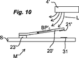
図9に示す第二実施例では、マイクロスイッチM’のメンブレーン20’は縦軸A’を有し、その一つの端部で、連結アーム22a’、22b’を介して、基板Sと一体化した一つ以上の固定台23’に接続されている。メンブレーン20’は、その縦軸A’と垂直の回転軸R’に従って旋回できる。前記連結アーム22a’、22b’は、メンブレーン20’と固定台23’間に弾性連結を生じさせ、メンブレーン20’が旋回する際には屈曲する。
In the second embodiment shown in FIG. 9, the
この第二実施形態では、マイクロスイッチM’の磁気作用を図10および図11に示す。これは永久磁石4’によって発生する磁場を印加するものである。この作用方式によれば、強磁性メンブレーン20は、永久磁石4’によって発生する磁場の磁力線Lに合わせて、二つの状態の間で移動する。永久磁石4’によって発生する磁場は、磁場の磁力線Lを有し、該磁力線Lの方向によって、メンブレーン20’の強磁性層に、その縦軸A’の方向に沿って磁気成分(BP’0,BP’1)を発生させる。このメンブレーン20’に発生する磁気成分(BP’0,BP’1)は、メンブレーン20’に開路(図10)または閉路(図11)の位置をとらせる磁気トルクを起こす。従って、永久磁石4’を移動させれば、永久磁石4’の磁場の二つの異なった方向の磁場の磁力線Lがメンブレーン20に与えられ、メンブレーン20’をその二つの位置間で移動させることができる。メンブレーン20’を移動させるためには、前記永久磁石4’を基板Sの表面30に対して平方方向、またはこの表面30に対して垂直方向に移動させることができる。
In the second embodiment, the magnetic action of the microswitch M ′ is shown in FIGS. This applies a magnetic field generated by the permanent magnet 4 '. According to this mode of operation, the
従って、装置の本体は、火薬5の点火手段をも内蔵しており、該点火手段は前述のマイクロスイッチM,M’および抵抗線9などの抵抗加熱素子などから構成され、マイクロスイッチM,M’によって制御されて、該抵抗加熱素子の加熱により火薬5の燃焼が開始される。上記マイクロスイッチM,M’は、上記抵抗線9に対して直列に配置され、マイクロスイッチM,M’が閉路になる場合、抵抗線9は一方がアースに、他方が主電気回路に接続される。抵抗線9は、火薬5と近接して、好ましくは接触した状態で、または埋め込まれた状態(実施例に示さず)で配置する。変形例として、抵抗線9を使用せずに、マイクロスイッチによって直接的に火薬5の燃焼を開始することもできる。すなわち、マイクロスイッチは、火薬5を点火するのに必要なエネルギーを発生させるように、所定の電流以上となった場合は揮発するように設計できる。このため、マイクロスイッチは、制御された電流が過度に強い場合に揮発するように、例えば可溶性のメンブレーン20を備える。
Therefore, the main body of the apparatus also incorporates an ignition means for the explosive 5, and the ignition means is composed of the above-mentioned resistance heating elements such as the microswitches M and M ′ and the resistance wire 9. And the combustion of the explosive 5 is started by heating the resistance heating element. The microswitches M and M ′ are arranged in series with respect to the resistance wire 9, and when the microswitches M and M ′ are closed, one of the resistance wires 9 is connected to the ground and the other is connected to the main electric circuit. The The resistance wire 9 is arranged close to the
遮断装置の第一構成を図1に示す。この遮断装置は外部の機械作用に反応するものである。この外部の機械作用は、例えば流体(空気、水、油)の圧力を上昇させること、また衝撃に応じて、あるいは温度の変動によって動く外部の機械部材からの作用など、各種の手段によって実施できる。その他、圧力、温度、速度などの各種の物理的パラメータの変動に応じる「マルチフィジクス」の検知器など、あらゆるタイプの検知器が考えられる。 A first configuration of the blocking device is shown in FIG. This shut-off device is responsive to external mechanical action. This external mechanical action can be implemented by various means, for example, by increasing the pressure of the fluid (air, water, oil), or by an action from an external mechanical member that moves in response to an impact or temperature fluctuation. . In addition, all types of detectors are conceivable, such as a “multiphysics” detector that responds to variations in various physical parameters such as pressure, temperature, and speed.
この第一構成では、装置は装置の軸Xに対して同軸である、外部からの機械作用が掛かる可動作用部材OAに取り付けられた、例えば円板またはトーラス状の可動永久磁石10を備える。この作用部材OAは、蛇腹機構11、または急速破裂式の弾性メンブレーン(図略)、または可動永久磁石10に対して同心である円板またはトーラス状の固定磁石(図略)によって、外部から最低強度の較正された機械作用を与えると並進移動できる。作用部材OAと連動して、可動永久磁石10は、装置の軸Xに従って、静止位置と作用位置間を並進できる。 In this first configuration, the device comprises, for example, a disc or torus-shaped movable permanent magnet 10 attached to a movable working member OA that is coaxial with the axis X of the device and is subject to external mechanical action. The action member OA is externally provided by a bellows mechanism 11, a rapid bursting elastic membrane (not shown), or a disk or torus-like fixed magnet (not shown) concentric with the movable permanent magnet 10. Translation is possible with the lowest calibrated mechanical action. In conjunction with the action member OA, the movable permanent magnet 10 can translate between the rest position and the action position according to the axis X of the device.
この第一構成において、使用されるマイクロスイッチM’は、前述の第二の実施例のタイプである。このマイクロスイッチM’は、可動永久磁石10によって発生する磁場の影響で揺動できるように、装置の軸Xに対してずれている。 In this first configuration, the microswitch M 'used is the type of the second embodiment described above. The microswitch M ′ is offset with respect to the axis X of the apparatus so that it can be swung under the influence of the magnetic field generated by the movable permanent magnet 10.
この遮断装置の第一構成は下記のように作用する。 The first configuration of this shut-off device operates as follows.
作用部材OAに外部から所定の最低強度の機械作用を与える場合、作用部材OAは装置の軸Xに従って並進移動し、可動永久磁石10を作動させる。例えば静止位置にある時、可動永久磁石は、マイクロスイッチM’に全く影響を及ぼさない。この時、マイクロスイッチM’のメンブレーン20’は、図9に示すように、基板と平行になる状態、または図10に示すように、内部の機械的プレストレスによって持ち上がった状態で静止位置にある。可動永久磁石10が低位置の作用位置にある場合は、その磁場が、マイクロスイッチM’を閉路位置(図11)にする磁気トルクをメンブレーン20’において発生させる。
When a predetermined minimum strength mechanical action is applied to the action member OA from the outside, the action member OA moves in translation according to the axis X of the apparatus and operates the movable permanent magnet 10. For example, when in the rest position, the movable permanent magnet has no effect on the microswitch M '. At this time, the
マイクロスイッチM’の閉路によって、急速に接地するので、抵抗線9は加熱し揮発して、火薬5を点火するのに必要なエネルギーを得る。 Since the microswitch M ′ is closed rapidly, the resistance wire 9 is heated and volatilized to obtain energy necessary to ignite the explosive 5.
火薬5の燃焼によって発生するガスは、破裂開始部8に従って本体1をバースティングさせると同時に接続部材7を押し出して、二つの導電体6a、6b間で主電気回路を遮断する。
The gas generated by the combustion of the explosive 5 causes the
図2に示す遮断装置の第二構成では、可動永久磁石10の代わりに装置の軸Xに配置された励起コイル40を使用する。従って、この遮断装置は、外部の機械作用にではなく、電気信号に反応する。
In the second configuration of the shut-off device shown in FIG. 2, an
この構成で使用されるマイクロスイッチMは、前述の第一実施形態のタイプである。従って、例えば基板Sと一体化された、最初にマイクロスイッチMを開路位置に維持する磁場B0を発生させる固定永久磁石(図略)によって分極化される。マイクロスイッチMは、ほぼ水平である磁力線の影響を受けるように、コイル40の軸に対してずれている。従って、コイル40が作動する時、マイクロスイッチMは、その基板Sと平行であって、そのメンブレーン20をその二つの位置間で制御する一時的な磁場Bc(図7)の影響を主に受ける。
The microswitch M used in this configuration is the type of the first embodiment described above. Therefore, it is polarized by, for example, a fixed permanent magnet (not shown) that is integrated with the substrate S and first generates a magnetic field B 0 that maintains the microswitch M in the open position. The microswitch M is offset with respect to the axis of the
図2において、励起コイル40はハウジングの周りに巻きついたコイルとして示されているが、他のいかなる形でもよいことを理解されたい。特に、図5に示すように、マイクロスイッチM’を支持する基板Sと一体化された平面タイプであってもよい。
In FIG. 2, the
励起コイル40は、主電気回路に対して並列に設置されるので、主電気回路の電流は励起コイル40を通る。コイル40で発生する磁場は、コイル40を通る電流に比例するので、該電流が保護される装置によって決定する所定の閾値を超える時、マイクロスイッチMは揺動できる。この閾値を越える時、励起コイル40で発生する一時的な磁場Bcは、マイクロスイッチMのメンブレーン20において、メンブレーン20を閉路位置(図7、図8)にするのに十分な強度のある磁気成分を発生させ、第一構成と同様に、火薬5の点火および接続部材7を押し出すことによって、主電気回路を遮断させる。
Since the
図3に示す投入装置も励起コイル400で作用するが、この場合、励起コイル400は、抵抗線9および使用されるマイクロスイッチM’と並列に設置される。この投入装置で使用されるマイクロスイッチM’は、上記の第一の実施例(図4〜図8)のタイプである。そのメンブレーン20は、固定永久磁石(図略)によって分極化され、コイル400によって発生する一時的な磁場Bcによって、その二つの位置間で制御される。上記のように、コイル400は、マイクロスイッチの基板Sと一体化した平面タイプ(図5)であってもよい。励起コイル400は、例えば検知器Cによって制御されて閉路する。この検知器Cは、例えば温度、圧力、加速などの一つ以上の物理的パラメータに反応する形式のスイッチであってもよい。特に、火薬5の点火制御用のマイクロスイッチMと直列に電気回路に設置される、本実施例によるMEMS式のマイクロスイッチを一つ以上備えた加速検知器が考えられる。例えば、永久磁石は、加速または減速の強度に応じて動くため、作動させるマイクロスイッチの数が変わる。加速または減速の閾値になると、全てのマイクロスイッチは閉路し、電流は励起コイル400に向かって流れる。
3 also operates with the
接続部材700はピストンPと一体に取り付けられ、前記ピストンPは本体1の内部空間を、火薬を含む第一チャンバー500と、導電体6a、6bが通り、接続部材700を含む第二チャンバー600とに区切る。ピストンPは、例えば本体1の内面に形成される溝300によって保持される。
The connecting
作用する際、コイル400が作動する時、その磁場はマイクロスイッチMに作用して、閉路位置にさせる。マイクロスイッチMの閉路により、火薬5が加熱され、その結果ガスが発生する。第一チャンバー500内に発生するガスは、二つの導電体6a、6bが接続されるまで、接続部材700とピストンPを一緒に並進に押す。装置には例えば第一チャンバー500から燃焼ガスを排気するための弁機構800を備えることができる。
In operation, when the
言うまでもなく、本発明の範囲にそむくことなく、他の変形や変更または均等手段の使用を想像することができる。 Of course, other variations and modifications or the use of equivalent means can be envisioned without departing from the scope of the present invention.
Claims (15)
−前記火薬(5)を点火する手段を有する
電気回路の投入/遮断装置であって、
−前記点火手段は前記電気回路に接続され、
−前記点火手段は前記火薬(5)の点火を制御できる磁気作用を持ったマイクロスイッチ(M、M’)を有することを特徴とする電気回路の投入/遮断装置。 -Explosives ( 5 ) that ignite to make or break electrical circuits, respectively;
An electrical circuit charging / disconnecting device comprising means for igniting said explosive ( 5 ) ,
The ignition means is connected to the electrical circuit;
-An electric circuit charging / cutting device, characterized in that the ignition means has a micro switch ( M, M ' ) having a magnetic action capable of controlling the ignition of the explosive ( 5 ) .
Applications Claiming Priority (3)
| Application Number | Priority Date | Filing Date | Title |
|---|---|---|---|
| FR0752763 | 2007-01-19 | ||
| FR0752763A FR2911719B1 (en) | 2007-01-19 | 2007-01-19 | DEVICE FOR INTERRUPTING / INITIATING AN ELECTRICAL CIRCUIT |
| PCT/EP2008/050434 WO2008090065A1 (en) | 2007-01-19 | 2008-01-16 | Device for switching on and off an electric circuit |
Publications (2)
| Publication Number | Publication Date |
|---|---|
| JP2010517212A JP2010517212A (en) | 2010-05-20 |
| JP5133354B2 true JP5133354B2 (en) | 2013-01-30 |
Family
ID=38135003
Family Applications (1)
| Application Number | Title | Priority Date | Filing Date |
|---|---|---|---|
| JP2009545914A Expired - Fee Related JP5133354B2 (en) | 2007-01-19 | 2008-01-16 | Electric circuit charging / shut-off device |
Country Status (10)
| Country | Link |
|---|---|
| US (1) | US8446241B2 (en) |
| EP (1) | EP2109871B1 (en) |
| JP (1) | JP5133354B2 (en) |
| CN (1) | CN101622684B (en) |
| AT (1) | ATE484068T1 (en) |
| DE (1) | DE602008002897D1 (en) |
| ES (1) | ES2352412T3 (en) |
| FR (1) | FR2911719B1 (en) |
| RU (1) | RU2410790C1 (en) |
| WO (1) | WO2008090065A1 (en) |
Families Citing this family (18)
| Publication number | Priority date | Publication date | Assignee | Title |
|---|---|---|---|---|
| US8659176B2 (en) * | 2010-04-15 | 2014-02-25 | Hanchett Entry Systems, Inc. | Electromagnetic energy harvester and a door latch release mechanism as an energy source for the harvester |
| US20130043111A1 (en) * | 2011-08-15 | 2013-02-21 | Honeywell International Inc. | Circuit breaker position sensing and health monitoring system |
| US9543745B2 (en) * | 2013-08-13 | 2017-01-10 | Cooper Technologies Company | Arrester bypass devices |
| DE102014115396A1 (en) * | 2014-10-22 | 2014-12-18 | Peter Lell | Disconnector for high DC or AC currents at high voltages |
| DE102015201371A1 (en) | 2015-01-27 | 2016-07-28 | Leoni Bordnetz-Systeme Gmbh | Pyrotechnic fuse element |
| RU2589035C1 (en) * | 2015-04-01 | 2016-07-10 | Российская Федерация, от имени которой выступает Государственная корпорация по атомной энергии "Росатом" | Device for making high-current electric circuits |
| US11239038B2 (en) * | 2015-05-18 | 2022-02-01 | Gigavac, Llc | Mechanical fuse device |
| US10566160B2 (en) * | 2015-05-18 | 2020-02-18 | Gigavac, Llc | Passive triggering mechanisms for use with switching devices incorporating pyrotechnic features |
| DE102016204287A1 (en) * | 2016-03-16 | 2017-09-21 | Bayerische Motoren Werke Aktiengesellschaft | DC OVERCURRENT PROTECTION DEVICE |
| KR102237377B1 (en) * | 2016-08-12 | 2021-04-06 | 삼성에스디아이 주식회사 | Electrical connector |
| FR3060834B1 (en) * | 2016-12-20 | 2019-05-24 | Airbus Safran Launchers Sas | PYROTECHNIC SHORT CIRCUIT |
| JP7441605B2 (en) * | 2018-01-02 | 2024-03-01 | ギガバック リミテッド ライアビリティ カンパニー | Contactor device with integrated pyrotechnic cutting function |
| TWI627651B (en) * | 2018-01-18 | 2018-06-21 | Nat Chung Shan Inst Science & Tech | Ripple type pressure switch |
| GB2612232B (en) * | 2018-08-27 | 2023-07-19 | Gigavac Llc | Passive triggering mechanisms for use with switching devices incorporating pyrotechnic features |
| US11276535B2 (en) * | 2018-08-28 | 2022-03-15 | Gigavac, Llc | Passive triggering mechanisms for use with switching devices incorporating pyrotechnic features |
| GB2577347A (en) * | 2018-09-24 | 2020-03-25 | Eaton Intelligent Power Ltd | Switch with pyrotechnic actuator |
| US11443910B2 (en) | 2019-09-27 | 2022-09-13 | Gigavac, Llc | Contact levitation triggering mechanisms for use with switching devices incorporating pyrotechnic features |
| WO2023071713A1 (en) * | 2021-10-27 | 2023-05-04 | 西安中熔电气股份有限公司 | Excitation protection apparatus with single excitation source acting step by step |
Family Cites Families (15)
| Publication number | Priority date | Publication date | Assignee | Title |
|---|---|---|---|---|
| US4342978A (en) * | 1979-03-19 | 1982-08-03 | S&C Electric Company | Explosively-actuated switch and current limiting, high voltage fuse using same |
| US4479105A (en) * | 1983-03-08 | 1984-10-23 | G & W Electric Company | Pyrotechnic current interrupter |
| JPH0356994Y2 (en) * | 1987-04-17 | 1991-12-25 | ||
| DE4406730A1 (en) * | 1994-03-02 | 1995-09-14 | Bayern Chemie Gmbh Flugchemie | Emergency current supply interruption device in motor vehicle |
| JPH09251829A (en) * | 1996-03-15 | 1997-09-22 | Fujitsu Takamizawa Component Kk | Shock sensor |
| US5732634A (en) * | 1996-09-03 | 1998-03-31 | Teledyne Industries, Inc. | Thin film bridge initiators and method of manufacture |
| US6107581A (en) * | 1998-02-17 | 2000-08-22 | Harness System Technologies Research, Ltd. | Circuit breaking device |
| JP2000251599A (en) * | 1999-03-03 | 2000-09-14 | Yazaki Corp | Power supply breaker |
| JP2001068000A (en) * | 1999-08-27 | 2001-03-16 | Yazaki Corp | Circuit breaker |
| US7336474B2 (en) * | 1999-09-23 | 2008-02-26 | Schlumberger Technology Corporation | Microelectromechanical devices |
| JP2001135217A (en) * | 1999-11-05 | 2001-05-18 | Yazaki Corp | Circuit breaker and wire harness unit using the same |
| FR2836907B1 (en) * | 2002-03-11 | 2005-03-18 | Commissariat Energie Atomique | MICROVANNE WITH PYROTECHNIC ACTUATION |
| DE102004062266A1 (en) * | 2004-12-23 | 2006-07-13 | Siemens Ag | Method and device for safe operation of a switching device |
| FR2880729B1 (en) * | 2005-01-10 | 2009-02-27 | Schneider Electric Ind Sas | MICROSYSTEM WITH ELECTROMAGNETIC CONTROL |
| US7538990B2 (en) * | 2006-12-14 | 2009-05-26 | Hamilton Sundstrand Corporation | High voltage DC contactor hybrid without a DC arc break |
-
2007
- 2007-01-19 FR FR0752763A patent/FR2911719B1/en not_active Expired - Fee Related
-
2008
- 2008-01-16 JP JP2009545914A patent/JP5133354B2/en not_active Expired - Fee Related
- 2008-01-16 DE DE602008002897T patent/DE602008002897D1/en active Active
- 2008-01-16 ES ES08707924T patent/ES2352412T3/en active Active
- 2008-01-16 WO PCT/EP2008/050434 patent/WO2008090065A1/en active Application Filing
- 2008-01-16 CN CN2008800060664A patent/CN101622684B/en not_active Expired - Fee Related
- 2008-01-16 US US12/523,668 patent/US8446241B2/en not_active Expired - Fee Related
- 2008-01-16 EP EP08707924A patent/EP2109871B1/en not_active Not-in-force
- 2008-01-16 RU RU2009131448/07A patent/RU2410790C1/en not_active IP Right Cessation
- 2008-01-16 AT AT08707924T patent/ATE484068T1/en not_active IP Right Cessation
Also Published As
| Publication number | Publication date |
|---|---|
| EP2109871A1 (en) | 2009-10-21 |
| JP2010517212A (en) | 2010-05-20 |
| US8446241B2 (en) | 2013-05-21 |
| DE602008002897D1 (en) | 2010-11-18 |
| EP2109871B1 (en) | 2010-10-06 |
| US20100089739A1 (en) | 2010-04-15 |
| CN101622684A (en) | 2010-01-06 |
| RU2410790C1 (en) | 2011-01-27 |
| ES2352412T3 (en) | 2011-02-18 |
| WO2008090065A1 (en) | 2008-07-31 |
| ATE484068T1 (en) | 2010-10-15 |
| CN101622684B (en) | 2012-04-04 |
| FR2911719A1 (en) | 2008-07-25 |
| FR2911719B1 (en) | 2009-02-27 |
Similar Documents
| Publication | Publication Date | Title |
|---|---|---|
| JP5133354B2 (en) | Electric circuit charging / shut-off device | |
| US11387061B2 (en) | Passive triggering mechanisms for use with switching devices incorporating pyrotechnic features | |
| US11443910B2 (en) | Contact levitation triggering mechanisms for use with switching devices incorporating pyrotechnic features | |
| US10388477B2 (en) | Contactor device integrating pyrotechnic disconnect features | |
| KR102173390B1 (en) | Contactor device integrating pyrotechnic disconnect features | |
| KR940000153B1 (en) | Underoil primary circuit breaker | |
| WO2020026859A1 (en) | Shut-off module | |
| JP2022538172A (en) | electrical circuit breaker | |
| JP2018517270A (en) | Mechanical fuse device | |
| US2655867A (en) | Fuze | |
| JP7405534B2 (en) | Passive trigger mechanism for use with switching devices incorporating pyrotechnic features | |
| US11276535B2 (en) | Passive triggering mechanisms for use with switching devices incorporating pyrotechnic features | |
| JPH02226634A (en) | Electric switch tripper and electric switch having the tripper | |
| US5089931A (en) | Safety device for electrical apparatus containing a dielectric gas, in particular circuit breakers or voltage-droppers for measurement purposes | |
| JPS5845129B2 (en) | fuse device | |
| CN220914149U (en) | Active and passive integrated protection device |
Legal Events
| Date | Code | Title | Description |
|---|---|---|---|
| A621 | Written request for application examination |
Free format text: JAPANESE INTERMEDIATE CODE: A621 Effective date: 20100827 |
|
| A977 | Report on retrieval |
Free format text: JAPANESE INTERMEDIATE CODE: A971007 Effective date: 20120618 |
|
| A131 | Notification of reasons for refusal |
Free format text: JAPANESE INTERMEDIATE CODE: A131 Effective date: 20120622 |
|
| A521 | Request for written amendment filed |
Free format text: JAPANESE INTERMEDIATE CODE: A523 Effective date: 20120921 |
|
| TRDD | Decision of grant or rejection written | ||
| A01 | Written decision to grant a patent or to grant a registration (utility model) |
Free format text: JAPANESE INTERMEDIATE CODE: A01 Effective date: 20121012 |
|
| A01 | Written decision to grant a patent or to grant a registration (utility model) |
Free format text: JAPANESE INTERMEDIATE CODE: A01 |
|
| A61 | First payment of annual fees (during grant procedure) |
Free format text: JAPANESE INTERMEDIATE CODE: A61 Effective date: 20121107 |
|
| FPAY | Renewal fee payment (event date is renewal date of database) |
Free format text: PAYMENT UNTIL: 20151116 Year of fee payment: 3 |
|
| R150 | Certificate of patent or registration of utility model |
Free format text: JAPANESE INTERMEDIATE CODE: R150 |
|
| LAPS | Cancellation because of no payment of annual fees |