JP5133266B2 - Transparent screen displaying images that can only be seen from one direction - Google Patents
Transparent screen displaying images that can only be seen from one direction Download PDFInfo
- Publication number
- JP5133266B2 JP5133266B2 JP2008557396A JP2008557396A JP5133266B2 JP 5133266 B2 JP5133266 B2 JP 5133266B2 JP 2008557396 A JP2008557396 A JP 2008557396A JP 2008557396 A JP2008557396 A JP 2008557396A JP 5133266 B2 JP5133266 B2 JP 5133266B2
- Authority
- JP
- Japan
- Prior art keywords
- polarizing plate
- transparent
- display
- visible
- film
- Prior art date
- Legal status (The legal status is an assumption and is not a legal conclusion. Google has not performed a legal analysis and makes no representation as to the accuracy of the status listed.)
- Expired - Fee Related
Links
- 230000000903 blocking effect Effects 0.000 claims 1
- 239000011521 glass Substances 0.000 description 4
- 239000000758 substrate Substances 0.000 description 4
- 230000010287 polarization Effects 0.000 description 3
- 238000010521 absorption reaction Methods 0.000 description 2
- 239000004973 liquid crystal related substance Substances 0.000 description 2
- 239000000463 material Substances 0.000 description 2
- 238000010276 construction Methods 0.000 description 1
- 238000009792 diffusion process Methods 0.000 description 1
- 238000012986 modification Methods 0.000 description 1
- 230000004048 modification Effects 0.000 description 1
- 230000001737 promoting effect Effects 0.000 description 1
- 230000001902 propagating effect Effects 0.000 description 1
Images


Classifications
-
- G—PHYSICS
- G03—PHOTOGRAPHY; CINEMATOGRAPHY; ANALOGOUS TECHNIQUES USING WAVES OTHER THAN OPTICAL WAVES; ELECTROGRAPHY; HOLOGRAPHY
- G03B—APPARATUS OR ARRANGEMENTS FOR TAKING PHOTOGRAPHS OR FOR PROJECTING OR VIEWING THEM; APPARATUS OR ARRANGEMENTS EMPLOYING ANALOGOUS TECHNIQUES USING WAVES OTHER THAN OPTICAL WAVES; ACCESSORIES THEREFOR
- G03B21/00—Projectors or projection-type viewers; Accessories therefor
- G03B21/54—Accessories
- G03B21/56—Projection screens
- G03B21/60—Projection screens characterised by the nature of the surface
- G03B21/62—Translucent screens
-
- G—PHYSICS
- G03—PHOTOGRAPHY; CINEMATOGRAPHY; ANALOGOUS TECHNIQUES USING WAVES OTHER THAN OPTICAL WAVES; ELECTROGRAPHY; HOLOGRAPHY
- G03B—APPARATUS OR ARRANGEMENTS FOR TAKING PHOTOGRAPHS OR FOR PROJECTING OR VIEWING THEM; APPARATUS OR ARRANGEMENTS EMPLOYING ANALOGOUS TECHNIQUES USING WAVES OTHER THAN OPTICAL WAVES; ACCESSORIES THEREFOR
- G03B21/00—Projectors or projection-type viewers; Accessories therefor
- G03B21/54—Accessories
- G03B21/56—Projection screens
- G03B21/60—Projection screens characterised by the nature of the surface
- G03B21/604—Polarised screens
-
- H—ELECTRICITY
- H04—ELECTRIC COMMUNICATION TECHNIQUE
- H04N—PICTORIAL COMMUNICATION, e.g. TELEVISION
- H04N5/00—Details of television systems
- H04N5/74—Projection arrangements for image reproduction, e.g. using eidophor
-
- H—ELECTRICITY
- H10—SEMICONDUCTOR DEVICES; ELECTRIC SOLID-STATE DEVICES NOT OTHERWISE PROVIDED FOR
- H10K—ORGANIC ELECTRIC SOLID-STATE DEVICES
- H10K2102/00—Constructional details relating to the organic devices covered by this subclass
- H10K2102/301—Details of OLEDs
- H10K2102/302—Details of OLEDs of OLED structures
- H10K2102/3023—Direction of light emission
- H10K2102/3031—Two-side emission, e.g. transparent OLEDs [TOLED]
-
- H—ELECTRICITY
- H10—SEMICONDUCTOR DEVICES; ELECTRIC SOLID-STATE DEVICES NOT OTHERWISE PROVIDED FOR
- H10K—ORGANIC ELECTRIC SOLID-STATE DEVICES
- H10K50/00—Organic light-emitting devices
- H10K50/80—Constructional details
- H10K50/868—Arrangements for polarized light emission
-
- H—ELECTRICITY
- H10—SEMICONDUCTOR DEVICES; ELECTRIC SOLID-STATE DEVICES NOT OTHERWISE PROVIDED FOR
- H10K—ORGANIC ELECTRIC SOLID-STATE DEVICES
- H10K59/00—Integrated devices, or assemblies of multiple devices, comprising at least one organic light-emitting element covered by group H10K50/00
- H10K59/80—Constructional details
- H10K59/8793—Arrangements for polarized light emission
Landscapes
- Physics & Mathematics (AREA)
- General Physics & Mathematics (AREA)
- Engineering & Computer Science (AREA)
- Multimedia (AREA)
- Signal Processing (AREA)
- Polarising Elements (AREA)
- Devices For Indicating Variable Information By Combining Individual Elements (AREA)
- Electroluminescent Light Sources (AREA)
- Overhead Projectors And Projection Screens (AREA)
- Transforming Electric Information Into Light Information (AREA)
- Liquid Crystal (AREA)
- Projection Apparatus (AREA)
Description
本発明は、表示装置に関し、特に表示装置の片側からしか画像が見えない透明な表示装置に関する。 The present invention relates to a display device, and more particularly to a transparent display device in which an image is visible only from one side of the display device.
一般的に言えば、広告は、特定のスポンサーによる商品、サービス、会社及びアイデアの有料の宣伝活動である。建造物側面上の広告は、20世紀初期には米国ではありふれたものであった。43番街のタイムズスクエアの NASDAQ Market Site の NASDAQ の看板は、1つの現代の事例である。2000年1月に公開され、建造費は3700万ドル掛かっている。この看板は、高さ120フィートで、世界最大のLED表示装置である。NASDAQは、この広告用のスペースを借りるのに毎年200万ドル以上を支払っている。この看板は他の宣伝形態で作り出されるものを遙かに凌駕する数の「印象」を作り出すので、これは、広告では良い取引だと実際には考えられている。しかしながら、建造物側面上の広告は、これがなければ建造物の窓に使うことのできる空間を覆ってしまうことになる。 Generally speaking, an advertisement is a paid promotional activity for goods, services, companies and ideas by a particular sponsor. Advertising on the side of buildings was common in the United States in the early 20th century. The NASDAQ signboard on the NASDAQ Market Site in Times Square on 43rd Avenue is a modern example. Published in January 2000, the construction costs $ 37 million. This signboard is 120 feet high and is the world's largest LED display. NASDAQ pays over $ 2 million annually to rent this advertising space. This sign is actually considered a good deal in advertising because it creates a number of “impressions” that far outweigh those produced by other forms of advertising. However, advertisements on the side of the building will cover the space that can be used for building windows without it.
したがって、広告スペースに窓を設けることのできる建造物側面上の広告を提供することが必要とされている。 Therefore, there is a need to provide advertisements on the side of a building that can be provided with windows in the advertising space.
本発明の1つの実施形態では、表示システムは、投影スクリーンと投影機を含んでいる。投影スクリーンは、偏光板と透明なスクリーンの間にリターダを含んでいる。投影機は、偏光板とリターダ板を通して透明なスクリーン上に画像を投影する。画像は、透明なスクリーンの第1の側からは見えるが、リターダ板を二度通過する光は偏光板によって遮断されるため、透明なスクリーンの第2の側からは見えない。この様に、投影スクリーンは、透明なスクリーンの第2の側にいる人の注意を画像によって乱すことはなく、第2の側にいる人には投影スクリーンを通して外が見えるようにしている。 In one embodiment of the invention, the display system includes a projection screen and a projector. The projection screen includes a retarder between the polarizing plate and the transparent screen. The projector projects an image on a transparent screen through a polarizing plate and a retarder plate. The image is visible from the first side of the transparent screen, but the light that passes twice through the retarder plate is blocked by the polarizer and is not visible from the second side of the transparent screen. In this way, the projection screen does not disturb the attention of the person on the second side of the transparent screen with the image, so that the person on the second side can see through the projection screen.
各図を通して、同じ参照番号は、同様又は同一の要素を示している。
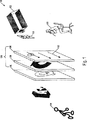
図1は、本発明の或る実施形態における背面投影式の透明な表示システム100を示している。システム100は、投影スクリーン104に向けて画像「Q」を生成する投影機102を含んでいる。投影機102は、液晶表示(LCD)投影機でも、デジタル光処理(DLP)投影機でも、レーザー投影機でも、何らかの他の投影装置でもよい。用途次第で、画像「Q」は、静止画像でも、静止画像のスライドでも、ビデオ映像でもよい。
Throughout the figures, the same reference numerals indicate similar or identical elements.
FIG. 1 illustrates a rear projection transparent display system 100 in one embodiment of the invention. System 100 includes a
投影スクリーン104は、偏光板106と、リターダ板108と、透明なスクリーン110を含んでいる。偏光板106とリターダ板108と透明なスクリーン110は、間隔を空けて示しているが、互いの上に直接取り付けてもよい。画像Qは、投影機102から偏光板106を貫いて伝播する。偏光板106を通過した後、画像Qは、偏向光のみを有している。或る実施形態では、偏光板106は線形偏光板であり、画像Qは、第1の方向112に沿って整列した線形偏向光のみを有している。偏光板106は、吸収、散乱、又は屈折によって光を偏光する。或る実施形態では、偏光板106は、線形偏光フィルムを貼ったガラスパネルである。或いは、偏光板106は、偏光材料で作られている。
The
画像Qは、次いでリターダ板108を通過して伝播し、透明なスクリーン110に当たる。或る実施形態では、リターダ板108は、四分の一波長板である。画像Qは、透明なスクリーン110に当たると、スクリーンの両側で見えるようになる。或る実施形態では、透明なスクリーン100は、ドイツの G+B pronova GmbH 製の HoloPro(商標)、デンマークの dnp Denmark 製の Holo Screen 又はカリフォルニア州ロサンゼルスの Laser Magic 製の TransScreen の様な、透明な拡散スクリーンである。
The image Q then propagates through the retarder plate 108 and strikes the
透明なスクリーン100から反射してリターダ板108を通る光は、全て、第1の方向とは直角な第2の方向に沿って線形に偏光され、したがって、、偏光板106によって遮断される。その結果、画像Qは、投影スクリーン104の一方の側からは見えるが、投影スクリーン104の他方の側からは見えなくなる。
All of the light reflected from the transparent screen 100 and passing through the retarder plate 108 is linearly polarized along a second direction perpendicular to the first direction and is therefore blocked by the
或る実施形態では、投影スクリーン104は、建造物の側面に設けられた窓又はガラス製の扉である。而して、建造物の外側の人114には、投影スクリーン104上の画像Qが見えるが、建造物の内側にいる人116には、投影スクリーン104上の画像Qが見えない。これによって、人116は、画像Qによって注意を乱されることはなく、同時に、非偏向光によって照らされた、対象物「A+」の様な投影スクリーン104の外側の対象物を見ることができる。
In some embodiments, the
システム100では、人116に、小さな画像Qが投影スクリーン104上に見えることもある。これは、投影機102が画像を非偏向光で投影し、それが部分的には偏光板106を透過し、部分的には偏光板106によって反射される時に起こる。小さな反射画像Qは、偏光方向112に沿って整列した光で画像を作るLCD投影機102を使用することによって回避することができる。代わりに、偏光方向112を有する追加の偏光板118を投影機102のレンズの前又は上に置いてもよい。
In the system 100, the
線形偏光板と四分の一波長板に上で具体的に触れたが、偏光板106とリターダ108は、偏光板106が、リターダ108を2度通過した画像Qからの反射光を全て遮断する限りにおいて、異なる偏光特性を有していてもよい。
The linear polarizing plate and the quarter-wave plate have been specifically mentioned above, but the polarizing
図2は、本発明の或る実施形態における透明な表示システム200を示している。表示システム200は、透明な表示装置202と、偏光板204を有している。透明な表示装置202と偏光板204は、間隔を空けて示しているが、互いの上に直接取り付けてもよい。
FIG. 2 illustrates a
透明な表示装置202は、表示装置の両側から見える画像「R」を生成する透明なスクリーンを有している。画像「R」は、透明な表示装置202の両側から伝播する偏向光で構成されている。用途次第で、画像Rは、静止画像でも、静止画像のスライドでも、ビデオ映像でもよい。
The
或る実施形態では、透明な表示装置202は、線形偏向光を放射する透明な有機発光ダイオード(OLED)表示装置である。図3は、OLED表示装置202が、透明な基板308上の透明なカソード304と透明なアノード306の間に挟まれた有機発光層302で構成されていることを示している。透明なOLED表示装置の一例は、ニュージャージー州ユーイングの Universal Display Corporation 製の TOLED(商標)である。線形偏向光を放射するため、方向層310がアノード302の上に形成され、次いで発光層302が方向層310の上に形成される。偏向光を放射する有機OLEDの一例は、Lauhof 他「Polarized Emission of PPV Oligonomer」2005年ドイツ液晶協会の協議会、に説明されている。
In some embodiments, the
図2に戻るが、画像Rの線形偏向光の一部は、透明な表示装置202から偏光板204へと伝播し、偏光板204は、線形偏向光がそれ以上進むのを妨げる。而して、画像Rは、表示システム200の一方の側からは見えるが、表示システム200の他方の側からは見えなくなる。偏光板204は、光を、吸収、散乱、及び屈折によって偏光する。或る実施形態では、偏光板204は線形偏光フィルムを貼ったガラスパネルである。或いは、偏光板204は、偏光材料で作られている。
Returning to FIG. 2, some of the linearly polarized light of the image R propagates from the
或る実施形態では、表示システム200は、建造物の側面に設けられた窓又はガラス製の扉の一部である。而して、建造物の外側の人206には、表示システム200上の画像Rが見えるが、建造物の内側にいる人208には、表示システム200上の画像Rが見えない。これによって、人208は、画像Rによって注意を乱されることはなく、同時に、非偏向光によって照らされた、対象物「A+」の様な表示システム200の外側の対象物を見ることができる。
In some embodiments,
或る実施形態では、一方向可視フィルム210が、透明な表示装置202と偏光板204の間に挿入されている。一方向可視フィルム210によって、人208には表示システム200を通して外が見みえるが、人206には表示システム200を通して建造物の中が見えることはない。或る実施形態では、一方向可視フィルム210は、透明な表示装置202に面する側には明るい色(例えば、白)、偏光板204に面する側には暗い色(例えば、黒)を有する有孔フィルムである。
In some embodiments, a unidirectional visible film 210 is inserted between the
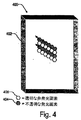
図4は、本発明の1つの実施形態における透明な表示システム400を示している。システム400は、不透明な発光画素404と透明な非発光画素406が交互に配置されているパターンを有するスクリーン402を含んでいる。したがって、スクリーン402は、光が透明な非発光画素406を通過できるので、少なくとも半透明には見える。
FIG. 4 illustrates a
不透明な発光画素404と透明な非発光画素406のパターンは、スクリーン402が半透明に見えるように両者が均等に分布している限りにおいて、変更することができる。或る実施形態では、このパターンは、不透明な発光画素404と透明な非発光画素406の線が交互に配置されて構成されている。或いは、図5に示すように、このパターンは、不透明な発光画素404に透明な非発光画素406を散在させて構成されている。
The pattern of the opaque
或る実施形態では、不透明な発光画素404は、透明なカソードとアノード及び不透明な基板を有するOLED画素である。透明なカソードとアノードは、これらの導線が透明な非発光画素を横切ってそれらの透明性を妨げることなく走ることができるようにするために必要である。不透明な基板は、OLED画素がスクリーン402の一方の側でのみ光を送ることができるようにするために必要である。或る実施形態では、透明な非発光画素406は、透明な基板を有し発光層を欠いているダミーのOLED画素に過ぎない。
In some embodiments, the opaque
開示している実施形態の特徴をこの他様々に改造し組み合わせたものも、本発明の範囲内にある。多種多様な実施形態が、特許請求の範囲によって包含されている。 Various other modifications and combinations of the features of the disclosed embodiments are within the scope of the present invention. A wide variety of embodiments are encompassed by the claims.
Claims (13)
第1の側及び第2の側から偏光した画像を能動的に発する透過的なディスプレイと、
該透過的なディスプレイの前記第1の側に設けられた偏光板であって、該偏光板に到達する前記偏光した画像からの光を実質的に遮って、該偏光した画像が実質的に前記透過的なディスプレイの前記第2の側からのみ見えるようになっている、偏光板と、
を具備し、
前記偏光板の側にいる人は、前記偏光した画像を見ることなく当該一方向に透過的なディスプレイシステムを通して見るようになっており、前記透過的なディスプレイの側にいる別の人は、前記偏光した画像を見るようになっている、
ことを特徴とするシステム。A unidirectionally transparent display system,
A transmissive display that actively emits polarized images from the first side and the second side;
A polarizing plate provided on the first side of the transmissive display, substantially blocking light from the polarized image reaching the polarizing plate, wherein the polarized image is substantially A polarizing plate, visible only from the second side of the transparent display;
Comprising
A person on the side of the polarizing plate is allowed to see through the unidirectionally transparent display system without seeing the polarized image, and another person on the side of the transparent display Seeing polarized images,
A system characterized by that.
該一方向可視フィルムは、前記偏光板の側にいる人に対しては当該一方向に透過的なディスプレイシステムを通して見ることを可能にするが、前記透過的なディスプレイの側にいる別の人に対しては当該一方向に透過的なディスプレイシステムを通して見ることができないようにする、請求項1に記載のシステム。Further comprising a unidirectional visible film between the transparent display and the polarizing plate;
The one-way visible film allows a person on the side of the polarizing plate to see through the one-way transmissive display system, but to another person on the side of the transmissive display. The system of claim 1, wherein the system is not visible through the one-way transmissive display system.
透過的なディスプレイの第1の側及び第2の側から偏光した画像を能動的に発する段階と、
前記透過的なディスプレイの前記第1の側において偏光板を用いて、前記偏光した画像からの光を遮って、該偏光した光が実質的に前記透過的なディスプレイの前記第2の側からのみ見えるようにする段階と、
を含み、
前記偏光板の側にいる人は、前記偏光した画像を見ることなく当該一方向に透過的なディスプレイシステムを通して見るようになっており、前記透過的なディスプレイの側にいる別の人は、前記偏光した画像を見るようになっている、
ことを特徴とする方法。A method for providing a unidirectionally transparent display system comprising:
Actively emitting polarized images from the first and second sides of the transmissive display;
A polarizing plate is used on the first side of the transmissive display to block light from the polarized image so that the polarized light is substantially only from the second side of the transmissive display. To make it visible,
Including
A person on the side of the polarizing plate is allowed to see through the unidirectionally transparent display system without seeing the polarized image, and another person on the side of the transparent display Seeing polarized images,
A method characterized by that.
前記一方向可視フィルムは、前記偏光板の側にいる人に対しては当該一方向に透過的なディスプレイシステムを通して見ることを可能にするが、前記透過的なディスプレイの側にいる別の人に対しては当該一方向に透過的なディスプレイシステムを通して見ることができないようにする、請求項8に記載の方法。Further comprising placing a unidirectional visible film between the transmissive display and the polarizing plate so as to be visible only from one direction;
The one-way visible film allows a person on the side of the polarizing plate to see through a display system that is transparent in the one direction, but to another person on the side of the transparent display. 9. The method of claim 8, wherein the method is not visible through the one-way transparent display system.
Applications Claiming Priority (3)
| Application Number | Priority Date | Filing Date | Title |
|---|---|---|---|
| US11/367,687 | 2006-03-03 | ||
| US11/367,687 US7854513B2 (en) | 2006-03-03 | 2006-03-03 | One-way transparent display systems |
| PCT/US2007/005360 WO2007103181A2 (en) | 2006-03-03 | 2007-02-27 | Transparent screen displaying images visible from one side only |
Publications (3)
| Publication Number | Publication Date |
|---|---|
| JP2009529144A JP2009529144A (en) | 2009-08-13 |
| JP2009529144A5 JP2009529144A5 (en) | 2010-04-15 |
| JP5133266B2 true JP5133266B2 (en) | 2013-01-30 |
Family
ID=38249262
Family Applications (1)
| Application Number | Title | Priority Date | Filing Date |
|---|---|---|---|
| JP2008557396A Expired - Fee Related JP5133266B2 (en) | 2006-03-03 | 2007-02-27 | Transparent screen displaying images that can only be seen from one direction |
Country Status (4)
| Country | Link |
|---|---|
| US (2) | US7854513B2 (en) |
| JP (1) | JP5133266B2 (en) |
| CN (2) | CN101887211A (en) |
| WO (1) | WO2007103181A2 (en) |
Families Citing this family (55)
| Publication number | Priority date | Publication date | Assignee | Title |
|---|---|---|---|---|
| US20090147185A1 (en) * | 2007-12-05 | 2009-06-11 | Emiscape, Inc. | Reflective One-Way Screen with Chromatic and Transparent Regions |
| EP2333863A1 (en) * | 2009-12-11 | 2011-06-15 | Nederlandse Organisatie voor toegepast -natuurwetenschappelijk onderzoek TNO | Electro-optical device, electrode therefore, and method and apparatus of manufacturing an electrode and the electro-optical device provided therewith |
| KR101290585B1 (en) * | 2009-12-15 | 2013-07-30 | 엘지디스플레이 주식회사 | Transparent display device |
| JP2013530135A (en) | 2010-04-30 | 2013-07-25 | アリゾナ ボード オブ リージェンツ アクティング フォー アンド オン ビハーフ オブ アリゾナ ステイト ユニバーシティ | Synthesis of tetracoordinate palladium complex and its application in light-emitting devices |
| TWI558713B (en) | 2011-04-14 | 2016-11-21 | 美國亞利桑那州立大學董事會 | Pyridine-oxyphenyl coordinated iridium (iii) complexes and methods of making and using |
| WO2012162488A1 (en) | 2011-05-26 | 2012-11-29 | Arizona Board Of Regents Acting For And On Behalf Of Arizona State University | Synthesis of platinum and palladium complexes as narrow-band phosphorescent emitters for full color displays |
| KR20130025613A (en) * | 2011-09-02 | 2013-03-12 | 한국전자통신연구원 | Organic light emitting diode and method of fabricating the same |
| FR2982376B1 (en) * | 2011-11-07 | 2014-01-03 | Laster | PORTABLE DEVICE OF INCREASED VISION. |
| JP5899884B2 (en) | 2011-12-12 | 2016-04-06 | セイコーエプソン株式会社 | Polarization conversion device and projector system |
| CN103365339B (en) * | 2012-03-26 | 2017-09-29 | 联想(北京)有限公司 | Method and electronic installation that transparent screen is shown |
| US9882150B2 (en) | 2012-09-24 | 2018-01-30 | Arizona Board Of Regents For And On Behalf Of Arizona State University | Metal compounds, methods, and uses thereof |
| US20150274762A1 (en) | 2012-10-26 | 2015-10-01 | Arizona Board Of Regents Acting For And On Behalf Of Arizona State University | Metal complexes, methods, and uses thereof |
| CN103018955A (en) * | 2012-12-27 | 2013-04-03 | 京东方科技集团股份有限公司 | Transparent display device, special glasses and display system |
| JP2015025968A (en) * | 2013-07-26 | 2015-02-05 | ソニー株式会社 | Presentation medium and display device |
| JP6804823B2 (en) | 2013-10-14 | 2020-12-23 | アリゾナ・ボード・オブ・リージェンツ・オン・ビハーフ・オブ・アリゾナ・ステイト・ユニバーシティーArizona Board of Regents on behalf of Arizona State University | Platinum complex and device |
| US10020455B2 (en) | 2014-01-07 | 2018-07-10 | Arizona Board Of Regents On Behalf Of Arizona State University | Tetradentate platinum and palladium complex emitters containing phenyl-pyrazole and its analogues |
| US10565925B2 (en) | 2014-02-07 | 2020-02-18 | Samsung Electronics Co., Ltd. | Full color display with intrinsic transparency |
| US10554962B2 (en) | 2014-02-07 | 2020-02-04 | Samsung Electronics Co., Ltd. | Multi-layer high transparency display for light field generation |
| US10375365B2 (en) | 2014-02-07 | 2019-08-06 | Samsung Electronics Co., Ltd. | Projection system with enhanced color and contrast |
| US10453371B2 (en) | 2014-02-07 | 2019-10-22 | Samsung Electronics Co., Ltd. | Multi-layer display with color and contrast enhancement |
| KR102208992B1 (en) * | 2014-05-12 | 2021-01-28 | 삼성디스플레이 주식회사 | Display device and manufacturing method of the same |
| US9941479B2 (en) | 2014-06-02 | 2018-04-10 | Arizona Board Of Regents On Behalf Of Arizona State University | Tetradentate cyclometalated platinum complexes containing 9,10-dihydroacridine and its analogues |
| US20160267851A1 (en) * | 2014-06-17 | 2016-09-15 | Nato Pirtskhlava | One Way Display |
| US10535292B2 (en) | 2014-06-17 | 2020-01-14 | Nato Pirtskhlava | One way display |
| US9923155B2 (en) | 2014-07-24 | 2018-03-20 | Arizona Board Of Regents On Behalf Of Arizona State University | Tetradentate platinum (II) complexes cyclometalated with functionalized phenyl carbene ligands and their analogues |
| US10793546B2 (en) | 2014-08-15 | 2020-10-06 | Arizona Board Of Regents On Behalf Of Arizona State University | Non-platinum metal complexes for excimer based single dopant white organic light emitting diodes |
| WO2016029137A1 (en) | 2014-08-22 | 2016-02-25 | Arizona Board Of Regents On Behalf Of Arizona State University | Organic light-emitting diodes with fluorescent and phosphorescent emitters |
| US10033003B2 (en) | 2014-11-10 | 2018-07-24 | Arizona Board Of Regents On Behalf Of Arizona State University | Tetradentate metal complexes with carbon group bridging ligands |
| US9865825B2 (en) | 2014-11-10 | 2018-01-09 | Arizona Board Of Regents On Behalf Of Arizona State University | Emitters based on octahedral metal complexes |
| US9665697B2 (en) * | 2015-03-17 | 2017-05-30 | International Business Machines Corporation | Selectively blocking content on electronic displays |
| US9879039B2 (en) | 2015-06-03 | 2018-01-30 | Arizona Board Of Regents On Behalf Of Arizona State University | Tetradentate and octahedral metal complexes containing naphthyridinocarbazole and its analogues |
| US11930662B2 (en) | 2015-06-04 | 2024-03-12 | Arizona Board Of Regents On Behalf Of Arizona State University | Transparent electroluminescent devices with controlled one-side emissive displays |
| US10158091B2 (en) | 2015-08-04 | 2018-12-18 | Arizona Board Of Regents On Behalf Of Arizona State University | Tetradentate platinum (II) and palladium (II) complexes, devices, and uses thereof |
| JP6806082B2 (en) * | 2015-12-01 | 2021-01-06 | Agc株式会社 | Transparent screen sheet, transparent screen, and video display system |
| CN105633292B (en) | 2016-03-24 | 2019-04-02 | 京东方科技集团股份有限公司 | A kind of organic electroluminescence device and preparation method thereof |
| US11335865B2 (en) | 2016-04-15 | 2022-05-17 | Arizona Board Of Regents On Behalf Of Arizona State University | OLED with multi-emissive material layer |
| US10177323B2 (en) | 2016-08-22 | 2019-01-08 | Arizona Board Of Regents On Behalf Of Arizona State University | Tetradentate platinum (II) and palladium (II) complexes and octahedral iridium complexes employing azepine functional groups and their analogues |
| US10822363B2 (en) | 2016-10-12 | 2020-11-03 | Arizona Board Of Regents On Behalf Of Arizona State University | Narrow band red phosphorescent tetradentate platinum (II) complexes |
| US11183670B2 (en) | 2016-12-16 | 2021-11-23 | Arizona Board Of Regents On Behalf Of Arizona State University | Organic light emitting diode with split emissive layer |
| WO2018140765A1 (en) | 2017-01-27 | 2018-08-02 | Jian Li | Metal-assisted delayed fluorescent emitters employing pyrido-pyrrolo-acridine and analogues |
| US10516117B2 (en) | 2017-05-19 | 2019-12-24 | Arizona Board Of Regents On Behalf Of Arizona State University | Metal-assisted delayed fluorescent emttters employing benzo-imidazo-phenanthridine and analogues |
| US11101435B2 (en) | 2017-05-19 | 2021-08-24 | Arizona Board Of Regents On Behalf Of Arizona State University | Tetradentate platinum and palladium complexes based on biscarbazole and analogues |
| US11037489B1 (en) * | 2017-05-22 | 2021-06-15 | Jerry Dewanye Alexander | High strength transparent articles with digital display arrays and capabilities |
| US20190064574A1 (en) * | 2017-08-30 | 2019-02-28 | Wuhan China Star Optoelectronics Semiconductor Display Technology Co., Ltd. | Display panel |
| CN111527615B (en) | 2017-10-17 | 2023-10-17 | 李健 | Phosphorescent excimer with preferred molecular orientation as monochromatic emitter for display and illumination applications |
| US11647643B2 (en) | 2017-10-17 | 2023-05-09 | Arizona Board Of Regents On Behalf Of Arizona State University | Hole-blocking materials for organic light emitting diodes |
| US12037348B2 (en) | 2018-03-09 | 2024-07-16 | Arizona Board Of Regents On Behalf Of Arizona State University | Blue and narrow band green and red emitting metal complexes |
| US12091429B2 (en) | 2018-07-16 | 2024-09-17 | Arizona Board Of Regents On Behalf Of Arizona State University | Fluorinated porphyrin derivatives for optoelectronic applications |
| US11878988B2 (en) | 2019-01-24 | 2024-01-23 | Arizona Board Of Regents On Behalf Of Arizona State University | Blue phosphorescent emitters employing functionalized imidazophenthridine and analogues |
| US11594691B2 (en) | 2019-01-25 | 2023-02-28 | Arizona Board Of Regents On Behalf Of Arizona State University | Light outcoupling efficiency of phosphorescent OLEDs by mixing horizontally aligned fluorescent emitters |
| JP2020170113A (en) * | 2019-04-04 | 2020-10-15 | マクセル株式会社 | Information display system and vehicular information display system utilizing the same |
| JP7348750B2 (en) * | 2019-05-31 | 2023-09-21 | マクセル株式会社 | Information display system and vehicle information display system using it |
| CN114127612A (en) * | 2019-07-04 | 2022-03-01 | 麦克赛尔株式会社 | Information display system with acute angle diffusion characteristic and image light control film used by same |
| US11785838B2 (en) | 2019-10-02 | 2023-10-10 | Arizona Board Of Regents On Behalf Of Arizona State University | Green and red organic light-emitting diodes employing excimer emitters |
| US11945985B2 (en) | 2020-05-19 | 2024-04-02 | Arizona Board Of Regents On Behalf Of Arizona State University | Metal assisted delayed fluorescent emitters for organic light-emitting diodes |
Family Cites Families (38)
| Publication number | Priority date | Publication date | Assignee | Title |
|---|---|---|---|---|
| US3248165A (en) * | 1964-02-24 | 1966-04-26 | Alvin M Marks | Moving screen projection system |
| US5066108A (en) | 1989-12-22 | 1991-11-19 | Hughes Aircraft Company | High throughput contrast enhancement for polarized displays |
| US5708522A (en) * | 1993-02-01 | 1998-01-13 | Levy; George S. | Antiglare optical device |
| JPH0752890A (en) | 1993-08-19 | 1995-02-28 | Jamco Corp | Window structure installed on the side surface of cabin of aircraft frame |
| US5469295A (en) | 1994-01-18 | 1995-11-21 | Burke; Douglas | Dual polarizing reflection filter three dimensional image creation and display system |
| US6548956B2 (en) | 1994-12-13 | 2003-04-15 | The Trustees Of Princeton University | Transparent contacts for organic devices |
| US5703436A (en) | 1994-12-13 | 1997-12-30 | The Trustees Of Princeton University | Transparent contacts for organic devices |
| JPH08201718A (en) * | 1995-01-31 | 1996-08-09 | Nippondenso Co Ltd | Display device |
| JPH1049063A (en) * | 1996-08-05 | 1998-02-20 | Dainippon Printing Co Ltd | Display system |
| US5986401A (en) * | 1997-03-20 | 1999-11-16 | The Trustee Of Princeton University | High contrast transparent organic light emitting device display |
| US6064521A (en) | 1997-05-14 | 2000-05-16 | Burke; Douglas | Polarizing resonant scattering three dimensional image screen and display systems |
| DE19843902A1 (en) | 1997-09-26 | 1999-04-01 | Denso Corp | Picture information display system e.g. for use in car show rooms |
| US6420031B1 (en) | 1997-11-03 | 2002-07-16 | The Trustees Of Princeton University | Highly transparent non-metallic cathodes |
| EP0966050A3 (en) | 1998-06-18 | 2004-11-17 | Osram Opto Semiconductors GmbH & Co. OHG | Organic light emitting diode |
| JP2000147428A (en) | 1998-11-06 | 2000-05-26 | Matsushita Electric Ind Co Ltd | Projection type image display device |
| JP3177640B2 (en) * | 1999-04-12 | 2001-06-18 | 経済産業省産業技術総合研究所長 | Polarized light emitting EL device using polysilane and method of manufacturing the same |
| JP2003521790A (en) | 2000-02-02 | 2003-07-15 | スリーエム イノベイティブ プロパティズ カンパニー | Touch screen having polarizer and method of manufacturing the same |
| US6639357B1 (en) | 2000-02-28 | 2003-10-28 | The Trustees Of Princeton University | High efficiency transparent organic light emitting devices |
| TW484238B (en) | 2000-03-27 | 2002-04-21 | Semiconductor Energy Lab | Light emitting device and a method of manufacturing the same |
| DE10035068A1 (en) | 2000-07-17 | 2002-01-31 | Daimler Chrysler Ag | Holographic display storing and reproducing spatial structure in color, is constructed from series of holographic screens, each with a separate projector |
| US6819486B2 (en) | 2001-01-17 | 2004-11-16 | 3M Innovative Properties Company | Projection screen having elongated structures |
| US6870670B2 (en) | 2001-04-06 | 2005-03-22 | 3M Innovative Properties Company | Screens and methods for displaying information |
| EP1393148B1 (en) * | 2001-05-02 | 2010-03-03 | Bitstream Inc. | Methods, systems, and programming for producing and displaying subpixel-optimized font bitmaps using non-linear color balancing |
| KR100483988B1 (en) | 2001-11-29 | 2005-04-15 | 삼성에스디아이 주식회사 | Method of Varying Transmittance in transparent conductive film |
| US20030214632A1 (en) | 2002-05-16 | 2003-11-20 | Jiaying Ma | Projection display system |
| US6811815B2 (en) | 2002-06-14 | 2004-11-02 | Avery Dennison Corporation | Method for roll-to-roll deposition of optically transparent and high conductivity metallic thin films |
| JP2004095340A (en) * | 2002-08-30 | 2004-03-25 | Seiko Instruments Inc | Self-luminous type display device |
| TW583466B (en) | 2002-12-09 | 2004-04-11 | Hannstar Display Corp | Structure of liquid crystal display |
| US6936960B2 (en) | 2003-01-10 | 2005-08-30 | Eastman Kodak Company | OLED displays having improved contrast |
| US6900458B2 (en) | 2003-02-21 | 2005-05-31 | Universal Display Corporation | Transflective display having an OLED backlight |
| US6873093B2 (en) | 2003-02-28 | 2005-03-29 | Motorola, Inc. | Organic light emitting diode display structure |
| US6933532B2 (en) | 2003-03-28 | 2005-08-23 | Eastman Kodak Company | OLED display with photosensor |
| US6894750B2 (en) | 2003-05-01 | 2005-05-17 | Motorola Inc. | Transflective color liquid crystal display with internal rear polarizer |
| JP4656872B2 (en) * | 2003-06-27 | 2011-03-23 | 株式会社半導体エネルギー研究所 | Display device and electronic device |
| JP2005227688A (en) * | 2004-02-16 | 2005-08-25 | Denso Corp | Transparent el display |
| US6961105B2 (en) * | 2004-03-05 | 2005-11-01 | Toppoly Optoelectronics Corp. | Dual-display module with a tunable mirror sheet |
| JP2006019638A (en) * | 2004-07-05 | 2006-01-19 | Nitto Denko Corp | Polarization light emitter, method for manufacturing same, polarization organic electroluminescence element, and liquid crystal display device |
| JP4822104B2 (en) * | 2005-01-21 | 2011-11-24 | 大日本印刷株式会社 | Projection system |
-
2006
- 2006-03-03 US US11/367,687 patent/US7854513B2/en not_active Expired - Fee Related
-
2007
- 2007-02-27 CN CN2010101921462A patent/CN101887211A/en active Pending
- 2007-02-27 JP JP2008557396A patent/JP5133266B2/en not_active Expired - Fee Related
- 2007-02-27 CN CNA2007800062839A patent/CN101390013A/en active Pending
- 2007-02-27 WO PCT/US2007/005360 patent/WO2007103181A2/en active Application Filing
-
2010
- 2010-11-12 US US12/945,080 patent/US8104895B2/en not_active Expired - Fee Related
Also Published As
| Publication number | Publication date |
|---|---|
| CN101887211A (en) | 2010-11-17 |
| CN101390013A (en) | 2009-03-18 |
| WO2007103181A3 (en) | 2007-12-27 |
| US8104895B2 (en) | 2012-01-31 |
| US20110057212A1 (en) | 2011-03-10 |
| US20070206156A1 (en) | 2007-09-06 |
| JP2009529144A (en) | 2009-08-13 |
| US7854513B2 (en) | 2010-12-21 |
| WO2007103181A2 (en) | 2007-09-13 |
Similar Documents
| Publication | Publication Date | Title |
|---|---|---|
| JP5133266B2 (en) | Transparent screen displaying images that can only be seen from one direction | |
| US8232718B2 (en) | Tiled electroluminescent device with filled gaps | |
| US7213930B2 (en) | Polarized projection display | |
| ES2785319T3 (en) | Double-sided display device | |
| US20080174735A1 (en) | Projection Display with Holographic Screen | |
| JP2008083510A (en) | Display device and display method | |
| KR101174550B1 (en) | two-way mirror screen system | |
| JP2003058069A (en) | Self-luminescence type picture display device | |
| US20200058718A1 (en) | Display substrate and method for manufacturing the same, display panel and method for manufacturing the same, and display device | |
| US7834956B2 (en) | Photoluminescent backlighting of and infrared transmissive visible light barrier for light valve | |
| US20130135560A1 (en) | Display device including sub-backlight | |
| JP2006234963A (en) | Liquid crystal display device | |
| JP2006079978A (en) | Light source device and display device | |
| US10146098B2 (en) | Transparent display device | |
| JP4932317B2 (en) | Display device | |
| US6861669B2 (en) | Compound display | |
| JP4341100B2 (en) | Liquid crystal display element | |
| CN116096166A (en) | Double-sided display panel and double-sided display device | |
| JP2006156751A (en) | Illuminator | |
| TWI293097B (en) | Illuminated logo unit | |
| KR102046650B1 (en) | Digital Signage Device | |
| JP2004226795A (en) | Three-dimensional image display device | |
| JP2003058070A (en) | Self-luminescence type picture display device | |
| JPH05204320A (en) | Light emitting display plate device | |
| JP2000228288A (en) | Light-emitting device and display device |
Legal Events
| Date | Code | Title | Description |
|---|---|---|---|
| A521 | Request for written amendment filed |
Free format text: JAPANESE INTERMEDIATE CODE: A523 Effective date: 20100223 |
|
| A621 | Written request for application examination |
Free format text: JAPANESE INTERMEDIATE CODE: A621 Effective date: 20100223 |
|
| A131 | Notification of reasons for refusal |
Free format text: JAPANESE INTERMEDIATE CODE: A131 Effective date: 20120514 |
|
| A521 | Request for written amendment filed |
Free format text: JAPANESE INTERMEDIATE CODE: A523 Effective date: 20120522 |
|
| TRDD | Decision of grant or rejection written | ||
| A01 | Written decision to grant a patent or to grant a registration (utility model) |
Free format text: JAPANESE INTERMEDIATE CODE: A01 Effective date: 20121009 |
|
| A01 | Written decision to grant a patent or to grant a registration (utility model) |
Free format text: JAPANESE INTERMEDIATE CODE: A01 |
|
| A61 | First payment of annual fees (during grant procedure) |
Free format text: JAPANESE INTERMEDIATE CODE: A61 Effective date: 20121107 |
|
| FPAY | Renewal fee payment (event date is renewal date of database) |
Free format text: PAYMENT UNTIL: 20151116 Year of fee payment: 3 |
|
| R150 | Certificate of patent or registration of utility model |
Free format text: JAPANESE INTERMEDIATE CODE: R150 |
|
| LAPS | Cancellation because of no payment of annual fees |