JP5130552B1 - Bread piece conveyor - Google Patents

Bread piece conveyor Download PDF

Info

Publication number
JP5130552B1
JP5130552B1 JP2012029859A JP2012029859A JP5130552B1 JP 5130552 B1 JP5130552 B1 JP 5130552B1 JP 2012029859 A JP2012029859 A JP 2012029859A JP 2012029859 A JP2012029859 A JP 2012029859A JP 5130552 B1 JP5130552 B1 JP 5130552B1
Authority
JP
Japan
Prior art keywords
conveyor
bread
upstream
downstream
piece
Prior art date
Legal status (The legal status is an assumption and is not a legal conclusion. Google has not performed a legal analysis and makes no representation as to the accuracy of the status listed.)
Active
Application number
JP2012029859A
Other languages
Japanese (ja)
Other versions
JP2013166613A (en
Inventor
安三 宮澤
Current Assignee (The listed assignees may be inaccurate. Google has not performed a legal analysis and makes no representation or warranty as to the accuracy of the list.)
Arplus Corp
Original Assignee
Miyazawa Co Ltd
Priority date (The priority date is an assumption and is not a legal conclusion. Google has not performed a legal analysis and makes no representation as to the accuracy of the date listed.)
Filing date
Publication date
Application filed by Miyazawa Co Ltd filed Critical Miyazawa Co Ltd
Priority to JP2012029859A priority Critical patent/JP5130552B1/en
Application granted granted Critical
Publication of JP5130552B1 publication Critical patent/JP5130552B1/en
Publication of JP2013166613A publication Critical patent/JP2013166613A/en
Active legal-status Critical Current
Anticipated expiration legal-status Critical

Links

Images

Landscapes

  • Discharge Of Articles From Conveyors (AREA)
  • Branching, Merging, And Special Transfer Between Conveyors (AREA)
  • Attitude Control For Articles On Conveyors (AREA)

Abstract

【課題】塊状の食パンをスライスしたパン片を上流側の1列状態から下流側での複数列状態に変換して効率よく搬送できるパン片コンベア装置を提供する。
【解決手段】上流コンベア54から後方側入口コンベア56Rのスペースにパン片103を受け渡す。シリンダ64の駆動により入口コンベア56を一体的に後方側へシフト移動し、上流コンベア54から前方側入口コンベア56Fのスペースに次のパン片103を受け渡す。シリンダ64の駆動により入口コンベア56を一体的に前方側へシフト移動する。前方側及び後方側入口コンベア56F、56R上のパン片103、103を出口コンベア57のスペースに受け渡した後、そのまま下流コンベア58に2列状態で受け渡す。
【選択図】図2
There is provided a bread piece conveyor device capable of efficiently conveying a bread piece obtained by slicing a lump of bread from a single row state on the upstream side to a plurality of rows on the downstream side.
A pan piece 103 is transferred from an upstream conveyor 54 to a space of a rear entrance conveyor 56R. By driving the cylinder 64, the inlet conveyor 56 is integrally shifted to the rear side, and the next bread piece 103 is delivered from the upstream conveyor 54 to the space of the front inlet conveyor 56F. The inlet conveyor 56 is integrally shifted to the front side by driving the cylinder 64. After the bread pieces 103 and 103 on the front and rear inlet conveyors 56F and 56R are transferred to the space of the outlet conveyor 57, they are transferred to the downstream conveyor 58 in two rows.
[Selection] Figure 2

Description

本発明は、塊状の食パンをスライスしたパン片を搬送するパン片コンベア装置に関する。   The present invention relates to a bread piece conveyor device for conveying bread pieces obtained by slicing chunks of bread.

例えばスライスしたパン片にバター塗布、トッピング等の処理を施してサンドイッチを作る場合、パン片を搬送する途中で1列から複数列に変換し、複数のラインでこれらの処理を行うことによって、生産能力を高めることができる。食品その他の処理ラインを複数列に変換する場合、特許文献1のように、水平方向又は上下方向に揺動する振分コンベアを搬送途中に設け、この振分コンベアを角度変更することにより複数の下流側のコンベアへ分配供給する装置が従来より知られている。このような振分装置では、所定の搬送方向に一括して大量に搬送した後搬送方向を切り換えるには都合がよいが、振分コンベアの角度変更に時間を要するため、搬送されてきたパン片を後続の複数のラインに次々に振り分けて供給することは困難である。また、振分コンベアを揺動する構造が複雑になり、揺動のための広いスペースも必要である。   For example, when making a sandwich by applying sliced bread pieces such as buttering and topping to make a sandwich, it is possible to produce by converting from one row to multiple rows while carrying the bread pieces and performing these treatments on multiple lines. Ability can be increased. When converting food and other processing lines into a plurality of rows, as disclosed in Patent Document 1, a sorting conveyor that swings in the horizontal direction or the vertical direction is provided in the middle of transportation, and the angle of the sorting conveyor is changed. An apparatus for distributing and supplying to a downstream conveyor is conventionally known. In such a sorting apparatus, it is convenient to switch the transport direction after transporting a large amount in a predetermined transport direction, but it takes time to change the angle of the distribution conveyor. It is difficult to distribute and supply to each of a plurality of subsequent lines. Further, the structure for swinging the sorting conveyor becomes complicated, and a wide space for swinging is also required.

特開2008−105833号公報JP 2008-105833 A

本発明の課題は、塊状の食パンをスライスしたパン片を上流側の1列状態から下流側での複数列状態に変換して効率よく搬送できるパン片コンベア装置を提供することにある。   The subject of this invention is providing the bread piece conveyor apparatus which converts the bread piece which sliced the block-shaped bread | bread bread from the 1st line state of the upstream side to the multiple row state in the downstream, and can convey it efficiently.

課題を解決するための手段及び発明の効果Means for Solving the Problems and Effects of the Invention

上記課題を解決するために、本発明は、
パン塊からスライスした1枚ずつのパン片を所定間隔で1列にして下流へ送る上流ベルトコンベアと、
その上流ベルトコンベアの下流側に接続され、該上流ベルトコンベアと交差する方向であるシフト方向にシフト可能に設けられ、かつ更に下流側へ前記パン片を複数並列に変換して送り出す振分装置と、
その振分装置の下流側へ接続され、該振分装置から複数並列状態で受け取ったパン片を下流側へ複数列のパン片として移動させる下流ベルトコンベアと、を含み、
前記振分装置は、前記上流ベルトコンベアに対し前記シフト方向に沿って並列状態となるように配置された複数の振分ベルトコンベアを全体が一体的にシフト可能に備えるとともに、
その複数設けられた個々の振分ベルトコンベアは、上流から搬送されるパン片のスライス面を受けるための複数のパン片スペースにそれぞれ対応して位置し、
前記複数の振分ベルトコンベアのうち上流からのパン片を前記パン片スペースで受け取るものだけ個別に駆動、かつ複数の振分ベルトコンベアが前記シフト方向に一体的にシフトする動作を伴ってパン片を複数並列させ、そのパン片を下流側へ送り出す動作を繰り返すコンベア制御装置を備えることを特徴とする。
In order to solve the above problems, the present invention provides:
An upstream belt conveyor that sends each piece of bread sliced from a loaf of bread in a row at a predetermined interval to the downstream;
A distribution device connected to the downstream side of the upstream belt conveyor, provided so as to be capable of shifting in a shift direction that intersects with the upstream belt conveyor, and further converting the bread pieces to a downstream side in parallel and sending them out; ,
A downstream belt conveyor connected to the downstream side of the sorting device and moving a plurality of bread pieces received in parallel from the sorting device to the downstream side as a plurality of rows of bread pieces,
The sorting apparatus includes a plurality of sorting belt conveyors arranged so as to be in parallel with the upstream belt conveyor along the shift direction, and the entire sorting apparatus can be integrally shifted, and
Each of the plurality of sorting belt conveyors provided is positioned corresponding to each of a plurality of bread piece spaces for receiving a slice surface of a bread piece conveyed from upstream,
With the operation of the shift integrally bread pieces the only ones to receive bread pieces spaces driven individually, and a plurality of sorting belt conveyors are the shift direction from the upstream of the plurality of sorting belt conveyors A conveyor control device that repeats an operation of arranging a plurality of bread pieces in parallel and sending the bread pieces downstream is provided .

上流コンベアと下流コンベアとの間に振分コンベアを設け、その振分コンベアの下流側への駆動搬送と、搬送方向に交差する方向へのシフト移動とによって、塊状の食パンをスライスしたパン片を上流側の1列状態から下流側での複数列状態に変換して効率よく搬送できる。また、振分コンベアの本数、シフト移動の回数等を変更することによって下流コンベアに形成される列数(ライン数)を調整することができる。   A sorting conveyor is provided between the upstream conveyor and the downstream conveyor, and a piece of bread sliced into a block of bread is driven and driven to the downstream side of the sorting conveyor and shifted in a direction crossing the conveying direction. It can be efficiently transported by converting from a single-row state on the upstream side to a multi-row state on the downstream side. Further, the number of lines (number of lines) formed on the downstream conveyor can be adjusted by changing the number of sorting conveyors, the number of shift movements, and the like.

実施形態として、上流コンベアを下流側へ駆動する第1駆動装置と、振分コンベアを下流側へ駆動する第2駆動装置と、振分コンベアをシフトさせるシフト装置と、下流コンベアを下流側へ駆動する第3駆動装置とを備え、コンベア制御装置は、少なくとも第2駆動装置とシフト装置とを関連付けて制御する。   As an embodiment, a first driving device that drives the upstream conveyor downstream, a second driving device that drives the sorting conveyor downstream, a shift device that shifts the sorting conveyor, and a downstream conveyor driving downstream The conveyor control device controls at least the second drive device and the shift device in association with each other.

実施形態として、上流コンベア、振分コンベア及び下流コンベアはいずれもベルトコンベアであり、振分コンベアは上流コンベアと直交する向きに長手状に形成されて幅広のベルトを備え、かつその長手方向に所定ピッチでシフトしてパン片を並列化するパン片スペースを作り、その幅広のベルトにパン片が並列に保持された状態で、振分コンベアの幅広のベルトが駆動されて並列化されたパン片を下流コンベアへ送り出す。   As an embodiment, the upstream conveyor, the distribution conveyor, and the downstream conveyor are all belt conveyors, and the distribution conveyor is formed in a longitudinal direction in a direction orthogonal to the upstream conveyor and includes a wide belt, and the longitudinal conveyor has a predetermined length in the longitudinal direction. A bread piece space is created by shifting the pitch to make the bread pieces parallel, and the bread pieces are held in parallel by the wide belt, and the wide belt of the sorting conveyor is driven to make the bread pieces parallel. To the downstream conveyor.

実施形態として、振分コンベアは、上流コンベアの下流端に隣接する入口コンベアと、下流コンベアの上流端に隣接する出口コンベアとを備え、それら入口コンベアと出口コンベアとはパン片の受渡しが可能なように隣接し、かつ互いに独立して上流コンベアと交差する方向にシフト可能であり、入口コンベアのシフトによりパン片が複数並列し、これが出口コンベアに受け渡され、その出口コンベアは入口コンベアのパン片の並列数を更に増加するようにシフトしてパン片を保持し、又は入口コンベアからの並列数のパン片をそのまま保持して、更に下流コンベアに複数並列したパン片を受け渡し、入口コンベアは出口コンベアが所定並列数のパン片を下流コンベアに受け渡す間に新たなパン片を上流コンベアから受け取り、自身のシフトにより並列化して出口コンベアに受け渡す行程に備え、このような全体の動作がコンベア制御装置の制御により実行される。このように振分コンベアを入口側と出口側に2本(以上)備えることによって、並べ替えたパン片を出口コンベアから下流コンベアへ受け渡す間に、新たなパン片を上流コンベアから入口コンベアへ受け渡すことができるから、待機時間を短縮しサイクルタイムを短くする上で有効である。   As an embodiment, the sorting conveyor includes an entrance conveyor adjacent to the downstream end of the upstream conveyor and an exit conveyor adjacent to the upstream end of the downstream conveyor, and the entrance conveyor and the exit conveyor can deliver bread pieces. Can be shifted in the direction crossing the upstream conveyor independently of each other, and by shifting the entrance conveyor, a plurality of bread pieces are arranged in parallel and delivered to the exit conveyor, and the exit conveyor is a pan of the entrance conveyor. Shifting the parallel number of pieces to increase further, holding the bread pieces, or holding the parallel number of bread pieces from the entrance conveyor as they are, and passing a plurality of parallel bread pieces to the downstream conveyor, While the exit conveyor delivers a predetermined number of bread pieces to the downstream conveyor, it receives new bread pieces from the upstream conveyor and shifts itself. Comprising the step of passing to the outlet conveyor by more parallel, such entire operation is performed by the control of the conveyor controller. By providing two (or more) sorting conveyors on the inlet side and the outlet side in this way, a new bread piece is transferred from the upstream conveyor to the inlet conveyor while the rearranged bread pieces are transferred from the outlet conveyor to the downstream conveyor. Since it can be delivered, it is effective for shortening the waiting time and shortening the cycle time.

パンスライス装置の一例を示す概略正面図。The schematic front view which shows an example of a bread slice apparatus. 本発明に係るパン片コンベア装置の一実施例を示す概略平面図。The schematic plan view which shows one Example of the bread piece conveyor apparatus which concerns on this invention. 図2の概略正面図。The schematic front view of FIG. 図3の入口側から見た概略側面図。The schematic side view seen from the entrance side of FIG. 図3の出口側から見た概略側面図。The schematic side view seen from the exit side of FIG. 図2のパン片コンベア装置におけるパン片の振り分け動作の一例を示す説明図。Explanatory drawing which shows an example of the distribution operation | movement of the bread piece in the bread piece conveyor apparatus of FIG. 本発明に係るパン片コンベア装置の他の実施例を示す概略平面図。The schematic plan view which shows the other Example of the bread piece conveyor apparatus which concerns on this invention. 図7の概略正面図。The schematic front view of FIG. 図8の入口側から見た概略側面図。The schematic side view seen from the entrance side of FIG. 図8の出口側から見た概略側面図。The schematic side view seen from the exit side of FIG. 図7のパン片コンベア装置におけるパン片の振り分け動作の一例を示す説明図。Explanatory drawing which shows an example of the bread | pan distribution operation | movement in the bread | pan piece conveyor apparatus of FIG. 図11Aに続く振り分け動作を示す説明図。Explanatory drawing which shows the distribution operation | movement following FIG. 11A. 図7のパン片コンベア装置におけるパン片の振り分け動作の他の例を示す説明図。Explanatory drawing which shows the other example of the sorting operation | movement of the bread piece in the bread piece conveyor apparatus of FIG. 図12Aに続く振り分け動作を示す説明図。Explanatory drawing which shows the distribution operation | movement following FIG. 12A. 図12Aに続く振り分け動作の変形例を示す説明図。Explanatory drawing which shows the modification of the distribution operation | movement following FIG. 12A. 本発明に係るパン片コンベア装置のさらに他の実施例をパン片の振り分け動作で示す説明図。Explanatory drawing which shows the further Example of the bread piece conveyor apparatus which concerns on this invention by the distribution operation | movement of a bread piece. 図13Aに続く振り分け動作を示す説明図。Explanatory drawing which shows the distribution operation | movement following FIG. 13A. 図13Bに続く振り分け動作を示す説明図。Explanatory drawing which shows the distribution operation | movement following FIG. 13B.

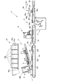
以下、本発明の実施の形態につき図面に示す実施例を参照して説明する。図1は本発明に係るパン片コンベア装置の上流側に位置するパンスライス装置の一例を示す。図1に示すパンスライス装置1は、図示しないオーブン等でブロック状に焼き上げたパン塊100を、例えばサンドイッチに適したスライス厚αの複数のスライスパン片101にスライスするために用いられる。   Hereinafter, embodiments of the present invention will be described with reference to examples shown in the drawings. FIG. 1 shows an example of a bread slicing device located upstream of a bread piece conveyor device according to the present invention. A bread slicing apparatus 1 shown in FIG. 1 is used to slice a bread lump 100 baked in a block shape in an oven (not shown) into a plurality of slice bread pieces 101 having a slice thickness α suitable for sandwiches, for example.

このパンスライス装置1は、パン塊100を下方へ間欠的に送るパン塊送り装置2と、パン塊送り装置2で送られたパン塊100の下端部をスライスする円板状の回転スライサー3と、回転スライサー3を往復駆動するスライサー往復駆動装置4と、回転スライサー3でスライスされた複数のスライスパン片101を順次下流に搬送する搬送コンベア5とを備えている。搬送コンベア5は、回転スライサー3の下方に位置する第1ベルトコンベア51と、その下流側に位置する第2ベルトコンベア52と、さらにその下流側に位置する第3ベルトコンベア53と、さらに下流側にてトッピング工程へ向かう第4ベルトコンベア54とを含む。なお、第4ベルトコンベア54は本発明の上流コンベアに相当する。   This bread slicing device 1 includes a bread loaf feeding device 2 that intermittently feeds the loaf loaf 100 downward, and a disk-shaped rotary slicer 3 that slices the lower end portion of the bread loaf 100 fed by the bread loaf feeding device 2. A slicer reciprocating drive device 4 that reciprocates the rotary slicer 3 and a conveyor 5 that sequentially conveys a plurality of slice pan pieces 101 sliced by the rotary slicer 3 downstream. The conveyor 5 includes a first belt conveyor 51 positioned below the rotary slicer 3, a second belt conveyor 52 positioned downstream thereof, a third belt conveyor 53 positioned further downstream thereof, and a further downstream side. And a fourth belt conveyor 54 heading to the topping process. The fourth belt conveyor 54 corresponds to the upstream conveyor of the present invention.

円板状の回転スライサー3は、第1ベルトコンベア51の搬送面51a(水平面)に対して、板面がスライス開始側ほど高くなるように、傾斜角θで鋭角(θ=5°〜30°程度)に傾斜した姿勢で設けられている。スライサー往復駆動装置4は、回転スライサー3を傾斜した姿勢と平行な鋭角傾斜方向へ往復駆動する。スライサー往復駆動装置4は、斜め下向きとなる往ストロークで回転スライサー3にスライス動作を行わせ、斜め上向きとなる復ストロークで退避動作を行わせる。パン塊送り装置2は、上方からパン塊100を回転スライサー3の往復駆動の軌道と交差する向き(図では直交する向き)に、スライス厚αに対応する距離ずつ間欠的に送る。このようにパン塊100を送る向きと回転スライサー3の傾斜軌道とが直交しているので、直角切りのスライスパン片101にスライスされる。また、パン塊送り装置2の送り方向は、第1ベルトコンベア51の搬送面51aに垂直な方向に対して、傾斜角θの傾きを有している。   The disk-shaped rotary slicer 3 has an acute angle (θ = 5 ° to 30 °) with respect to the transport surface 51a (horizontal plane) of the first belt conveyor 51 so that the plate surface becomes higher toward the slice start side. Grade). The slicer reciprocating drive device 4 drives the rotary slicer 3 to reciprocate in an acute inclination direction parallel to the inclined posture. The slicer reciprocating drive device 4 causes the rotary slicer 3 to perform a slicing operation with a forward stroke that is obliquely downward, and to perform a retreat operation with a backward stroke that is obliquely upward. The bread lump feeding device 2 intermittently feeds the bread lump 100 from above at a distance corresponding to the slice thickness α in a direction intersecting with the reciprocating drive trajectory of the rotary slicer 3 (direction orthogonal in the figure). Since the direction in which the bread lump 100 is fed and the inclined orbit of the rotary slicer 3 are orthogonal to each other, the slice bread pieces 101 are sliced into right-angled slices. Further, the feeding direction of the bread loaf feeding device 2 has an inclination of an inclination angle θ with respect to a direction perpendicular to the conveying surface 51 a of the first belt conveyor 51.

パン塊供給装置91は、複数の縦枠91bで連結され、固定の案内枠91cにガイドされて周回移動する垂直コンベア91aを有する。直方体形状あるいは正四角柱形状のパン塊100を縦枠91b間に1個ずつ挿入し、垂直コンベア91aを周回させると、先頭のパン塊100は案内枠91cによってパン塊送り装置2の上方で斜め(傾斜角θ)に姿勢変更されて落下し、パン塊送り装置2へ供給される。   The bread lump supply device 91 includes a vertical conveyor 91a that is connected by a plurality of vertical frames 91b and that moves around while being guided by a fixed guide frame 91c. When the rectangular parallelepiped-shaped or square prism-shaped bread loaf 100 is inserted one by one between the vertical frames 91b and the vertical conveyor 91a is circulated, the top bread loom 100 is obliquely above the bread loaf feeder 2 by the guide frame 91c ( The posture is changed to an inclination angle θ), and it is dropped and supplied to the bread lump feeder 2.

第2ベルトコンベア52(搬送面52a)には、スライスパン片101の耳部102を切断する耳落とし装置6が設けられている。第2ベルトコンベア52の終端部(下流側端部)及び第3ベルトコンベア53の始端部(上流側端部)に跨って、耳部102を収容する耳部回収容器7が設けられている。なお、パンスライス装置1には、パン塊100を1個ずつパン塊送り装置2へ供給するパン塊供給装置91と、耳落とし装置6による耳落とし前に第1ベルトコンベア51上のスライスパン片101の位置を一定の状態に揃える整列装置92と、1個のパン塊100から最初と最後にスライスされる端部パン片105を第1ベルトコンベア51上から除去する除去装置93も設けられている。   The second belt conveyor 52 (conveying surface 52 a) is provided with an ear drop device 6 that cuts the ear portion 102 of the slice bread piece 101. An ear collection container 7 that accommodates the ear 102 is provided across the terminal end (downstream end) of the second belt conveyor 52 and the start end (upstream end) of the third belt conveyor 53. The bread slicing device 1 includes a bread loaf supply device 91 that supplies the loaf 100 to the bread loaf feeding device 2 one by one, and a slice bread piece 101 on the first belt conveyor 51 before the ear drop by the ear drop device 6. An aligning device 92 that aligns the positions of the pans 105 and a removing device 93 that removes the end bread pieces 105 that are sliced first and last from one bread loaf 100 from the first belt conveyor 51 are also provided. .

また、第3ベルトコンベア53(搬送面53a)にはバター塗布装置94が設けられ、ホッパー94a内に貯留されたバターやマーガリンを回転する転写ローラー94bの表面に一時的に塗り、耳部102を切り落とされた耳なしパン片103(以下単にパン片という)のスライス面にそのバターを塗布する(一種の転写形態をとる)。補助ローラー94cは、転写ローラー94bの押し付けによる耳なしパン片103及び第3ベルトコンベア53の下方への撓み量を所定範囲内に留めるために、転写ローラー94bと対向する形で第三ベルトコンベア53と下面側で接している。転写ローラー94bはモータ等によって回転駆動されるが、補助ローラー94cは非駆動の遊転状態であってもよい。   The third belt conveyor 53 (conveying surface 53a) is provided with a butter coating device 94, and temporarily coats the surface of the transfer roller 94b for rotating the butter and margarine stored in the hopper 94a, and the ear portion 102 is applied. The butter is applied to the sliced surface of the cut earless bread piece 103 (hereinafter simply referred to as bread piece) (takes a kind of transfer form). The auxiliary roller 94c is opposed to the transfer roller 94b in order to keep the amount of bending downward of the earless bread piece 103 and the third belt conveyor 53 due to the pressing of the transfer roller 94b within a predetermined range. In contact with the lower surface. The transfer roller 94b is rotationally driven by a motor or the like, but the auxiliary roller 94c may be in a non-driven idle state.

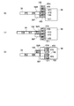
図2〜図5に示すパン片コンベア装置10は上記パンスライス装置1の下流側に位置し、上流コンベア54(第4ベルトコンベア)ではパン片103が1枚ずつ所定間隔で1列に搬送される状態から、下流コンベア58ではパン片103が2列で搬送される状態に変換する。下流コンベア58には2列のトッピング作業ラインが形成される。パン片コンベア装置10は、上流コンベア54と、上流コンベア54の下流端に供給ローラコンベア55を介して接続される振分コンベア56,57と、振分コンベアの下流側に接続される下流コンベア58とを有する。なお、供給ローラコンベア55は上流コンベア54の下流端と入口コンベア56の上流端とを中継する遊転ローラであって、パン片103の供給速度を調整している。   The bread piece conveyor device 10 shown in FIGS. 2 to 5 is located on the downstream side of the bread slicing device 1, and on the upstream conveyor 54 (fourth belt conveyor), the bread pieces 103 are conveyed one by one in a row at predetermined intervals. The state is changed to a state in which the bread pieces 103 are conveyed in two rows on the downstream conveyor 58. Two rows of topping work lines are formed on the downstream conveyor 58. The bread piece conveyor device 10 includes an upstream conveyor 54, sorting conveyors 56 and 57 connected to the downstream end of the upstream conveyor 54 via a supply roller conveyor 55, and a downstream conveyor 58 connected to the downstream side of the sorting conveyor. And have. The supply roller conveyor 55 is an idle roller that relays the downstream end of the upstream conveyor 54 and the upstream end of the entrance conveyor 56, and adjusts the supply speed of the bread pieces 103.

振分コンベアは、上流コンベア54の下流端に位置する入口コンベア56と、下流コンベア58の上流端に隣接する出口コンベア57とを有する。入口コンベア56と出口コンベア57とはパン片103の受渡しが可能なように搬送方向(図2の左右方向)に隣接し、互いに独立して駆動搬送可能である。また、入口コンベア56は上流コンベア54と交差する方向(図では直交する方向、すなわち図2の上下方向)にシフト移動可能である。なお、この実施例では出口コンベア57はシフト移動せず固定状態である。   The sorting conveyor has an entrance conveyor 56 located at the downstream end of the upstream conveyor 54 and an exit conveyor 57 adjacent to the upstream end of the downstream conveyor 58. The entrance conveyor 56 and the exit conveyor 57 are adjacent to each other in the transport direction (left-right direction in FIG. 2) so that the bread pieces 103 can be delivered, and can be driven and transported independently of each other. Further, the entrance conveyor 56 can be shifted in a direction intersecting with the upstream conveyor 54 (a direction orthogonal in the figure, that is, a vertical direction in FIG. 2). In this embodiment, the exit conveyor 57 does not shift and is in a fixed state.

入口コンベア56は前方側入口コンベア56Fと後方側入口コンベア56Rとから構成され、これらのコンベア56F、56Rは上流コンベア54と直交する方向(前後方向、すなわち図2の上下方向)に隣接して設けられている。各入口コンベア56F、56Rは1枚のパン片103よりやや大きい搬送面を有し、上流コンベア54から1枚のパン片103を受け取り、下流側の出口コンベア57に受け渡す。したがって、入口コンベア56全体としては、上流コンベア54と直交する向きにパン片複数枚分(この実施例では2枚分)の長手状並列化スペースを有する幅広のベルトに形成される。以下の記載では、前方側及び後方側入口コンベア56F、56Rを包括する場合に入口コンベア56と表す。   The entrance conveyor 56 includes a front-side entrance conveyor 56F and a rear-side entrance conveyor 56R, and these conveyors 56F and 56R are provided adjacent to a direction perpendicular to the upstream conveyor 54 (the front-rear direction, that is, the vertical direction in FIG. 2). It has been. Each of the entrance conveyors 56F and 56R has a conveyance surface that is slightly larger than one bread piece 103, receives one bread piece 103 from the upstream conveyor 54, and transfers it to the downstream outlet conveyor 57. Therefore, the entire entrance conveyor 56 is formed as a wide belt having a plurality of bread pieces in a direction perpendicular to the upstream conveyor 54 (two sheets in this embodiment). In the following description, when the front side and the rear side entrance conveyors 56F and 56R are included, it is expressed as the entrance conveyor 56.

前方側入口コンベア56F(又は後方側入口コンベア56R)は、駆動プーリ56aと2つの従動プーリ56bとに掛け回されたベルトコンベアであり、第2駆動装置としての前方側入口コンベアモータ61F(又は後方側入口コンベアモータ61R)により、タイミングベルト61a及びタイミングプーリ61bを介し各々独立して駆動される。従動プーリ56b,56b間の上面が搬送面に形成される。また、入口コンベア56は空気圧式又は油圧式の入口シフト用シリンダ64(シフト装置)により、一体的に前後方向にシフト可能である。具体的には、入口シフト用シリンダ64の駆動により、フレーム11に前後方向に固定された直線状案内部材64a(通称リニアガイド)に沿って、前方側及び後方側入口コンベア56F、56Rの支持フレーム64bが直線移動する。   The front-side inlet conveyor 56F (or the rear-side inlet conveyor 56R) is a belt conveyor that is wound around the drive pulley 56a and the two driven pulleys 56b, and the front-side inlet conveyor motor 61F (or the rear side) as a second driving device. The side inlet conveyor motor 61R) is independently driven via the timing belt 61a and the timing pulley 61b. An upper surface between the driven pulleys 56b and 56b is formed on the transport surface. The inlet conveyor 56 can be integrally shifted in the front-rear direction by a pneumatic or hydraulic inlet shift cylinder 64 (shift device). Specifically, the support frames of the front and rear inlet conveyors 56F and 56R are driven along a linear guide member 64a (commonly referred to as a linear guide) fixed to the frame 11 in the front-rear direction by driving the inlet shift cylinder 64. 64b moves linearly.

出口コンベア57は、上流コンベア54と直交する向きにパン片複数枚分(この実施例では2枚分)の長手状並列化スペースを有する幅広のベルトで構成され、入口コンベア56とほぼ等しい広さの搬送面を有する。出口コンベア57は、駆動プーリ57aと2つの従動プーリ57bに掛け回されたベルトコンベアであり、第2駆動装置としての出口コンベアモータ62により、タイミングベルト62a及びタイミングプーリ62bを介し駆動される。従動プーリ57b,57b間の上面が搬送面に形成される。   The exit conveyor 57 is configured by a wide belt having a longitudinal parallel space for a plurality of bread pieces (in this embodiment, two sheets) in a direction orthogonal to the upstream conveyor 54, and is approximately equal in width to the entrance conveyor 56. Having a transfer surface. The outlet conveyor 57 is a belt conveyor wound around a driving pulley 57a and two driven pulleys 57b, and is driven by an outlet conveyor motor 62 as a second driving device via a timing belt 62a and a timing pulley 62b. An upper surface between the driven pulleys 57b and 57b is formed on the transport surface.

なお、上流コンベア54は第1駆動装置としての上流コンベアモータ60(図2参照)により、下流コンベア58は第3駆動装置としての下流コンベアモータ63(図2参照)によりそれぞれ駆動される。   The upstream conveyor 54 is driven by an upstream conveyor motor 60 (see FIG. 2) as a first driving device, and the downstream conveyor 58 is driven by a downstream conveyor motor 63 (see FIG. 2) as a third driving device.

入口コンベア56の上方に架設された門型形状の入口側フレーム66aには、前方側及び後方側入口コンベア56F、56Rの各搬送面におけるパン片103の存否を検出する前方側及び後方側入口コンベア用光電センサ66F、66R(パン片検出手段)が設けられている。同様に、出口コンベア57の上方に架設された門型形状の出口側フレーム67aには、出口コンベア57の搬送面におけるパン片103の存否を2ヶ所で検出する出口コンベア用光電センサ67、67(パン片検出手段)が設けられている。   A portal-shaped entrance-side frame 66a installed above the entrance conveyor 56 has a front-side and a rear-side entrance conveyor that detects the presence or absence of the bread pieces 103 on the transport surfaces of the front-side and rear-side entrance conveyors 56F, 56R. Photoelectric sensors 66F and 66R (bread piece detecting means) are provided. Similarly, the exit-shaped photoelectric sensors 67 and 67 (for detecting the presence or absence of the bread pieces 103 on the conveyance surface of the exit conveyor 57 at two locations are provided on a portal-shaped exit-side frame 67a installed above the exit conveyor 57. Bread piece detecting means) is provided.

光電センサ66F、66R、67、67の検知信号、コンベアモータ60、61F、61R、62、63及びシリンダ64の位置データ等はコントローラ70(コンベア制御装置)に入力される。そして、1列搬送状態から2列搬送状態に変換するための動作指令信号が、コントローラ70からコンベアモータ60、61F、61R、62、63及びシリンダ64に出力される。つまり、振分コンベア(入口コンベア56、出口コンベア57)のパン片スペースに対応してパン片103の存否を検出するパン片検出手段(光電センサ66F、66R、67、67)が設けられ、コンベア制御装置(コントローラ70)は、パン片検出手段の存否検出信号や振分コンベアの駆動装置(コンベアモータ61F、61R、62)及びシフト装置(シリンダ64)の位置データに基づいて駆動装置とシフト装置とを制御する。   The detection signals of the photoelectric sensors 66F, 66R, 67, 67, the position data of the conveyor motors 60, 61F, 61R, 62, 63, and the cylinder 64 are input to the controller 70 (conveyor control device). Then, an operation command signal for converting from the one-row conveyance state to the two-row conveyance state is output from the controller 70 to the conveyor motors 60, 61F, 61R, 62, 63 and the cylinder 64. That is, bread piece detecting means (photoelectric sensors 66F, 66R, 67, 67) for detecting the presence or absence of the bread piece 103 corresponding to the bread piece space of the sorting conveyor (inlet conveyor 56, outlet conveyor 57) is provided. The control device (controller 70) includes a drive device and a shift device based on the presence / absence detection signal of the bread piece detection means and the position data of the distribution conveyor drive devices (conveyor motors 61F, 61R, 62) and the shift device (cylinder 64). And control.

次に、パン片コンベア装置10を用いて1列のパン片を2列に振り分ける手順を、図2〜図5を参照しつつ図6に基づいて説明する。なお、図6の全工程中、上流コンベア54(上流コンベアモータ60)と下流コンベア58(下流コンベアモータ63)とは常時駆動可能である。また、図6では上流コンベア54が入口コンベア56に重なるまで伸びてパン片103を受け渡すように表されているが、これは受け渡しを象徴的に表すためであり、上流コンベア54が伸縮するわけではない(図11A以降の説明図においても同様)。   Next, a procedure for distributing one row of bread pieces into two rows using the bread piece conveyor device 10 will be described based on FIG. 6 with reference to FIGS. Note that the upstream conveyor 54 (upstream conveyor motor 60) and the downstream conveyor 58 (downstream conveyor motor 63) can be driven at all times during the entire process of FIG. In FIG. 6, the upstream conveyor 54 extends to overlap with the entrance conveyor 56 so as to deliver the bread pieces 103, but this is to symbolize the delivery, and the upstream conveyor 54 is expanded and contracted. This is not the case (the same applies to the explanatory diagrams of FIG. 11A and subsequent figures).

(1)モータ61Rの駆動により後方側入口コンベア56Rを回転して、上流コンベア54から後方側入口コンベア56Rのスペースにパン片103を受け渡す。光電センサ66Rがパン片103を検知すると直ちに後方側入口コンベア56Rの回転を停止する。この間出口コンベア57は回転を停止している。
(2)シリンダ64の駆動により入口コンベア56を一体的に後方側へシフト移動し、続いてモータ61Fの駆動により前方側入口コンベア56Fを回転して、上流コンベア54から前方側入口コンベア56Fのスペースに次のパン片103を受け渡す。光電センサ66F、66Rがともにパン片103を検知すると直ちに前方側入口コンベア56Fの回転を停止する。この間出口コンベア57は回転を停止している。
(1) The rear entrance conveyor 56R is rotated by driving the motor 61R, and the bread pieces 103 are delivered from the upstream conveyor 54 to the space of the rear entrance conveyor 56R. As soon as the photoelectric sensor 66R detects the bread piece 103, the rotation of the rear entrance conveyor 56R is stopped. During this time, the outlet conveyor 57 stops rotating.
(2) The inlet conveyor 56 is integrally shifted rearward by driving the cylinder 64, and then the front inlet conveyor 56F is rotated by driving the motor 61F, so that the space from the upstream conveyor 54 to the front inlet conveyor 56F. The next bread piece 103 is delivered to. As soon as the photoelectric sensors 66F and 66R detect the bread piece 103, the rotation of the front entrance conveyor 56F is stopped. During this time, the outlet conveyor 57 stops rotating.

(3)シリンダ64の駆動により入口コンベア56を一体的に前方側へシフト移動する。
(4)続いてモータ61F、61Rの駆動により前方側及び後方側入口コンベア56F、56Rを回転し、さらにモータ62の駆動により出口コンベア57を回転して、前方側及び後方側入口コンベア56F、56R上のパン片103、103を出口コンベア57のスペースに2列状態で受け渡す。光電センサ66F、66Rがともにパン片103を検知しなくなると直ちに前方側及び後方側入口コンベア56F、56Rの回転を停止する。
(3) The inlet conveyor 56 is integrally shifted forward by driving the cylinder 64.
(4) Subsequently, the front and rear inlet conveyors 56F and 56R are rotated by driving the motors 61F and 61R, and the outlet conveyor 57 is further rotated by driving the motor 62, so that the front and rear inlet conveyors 56F and 56R are rotated. The upper bread pieces 103 and 103 are transferred to the space of the exit conveyor 57 in a two-row state. As soon as the photoelectric sensors 66F and 66R no longer detect the bread piece 103, the rotation of the front and rear entrance conveyors 56F and 56R is stopped.

(5)出口コンベア57上のパン片103、103はそのまま下流コンベア58に2列状態で受け渡される。光電センサ67、67がともにパン片103を検知しなくなると直ちに出口コンベア57の回転を停止する。この間にモータ61Rの駆動により後方側入口コンベア56Rを回転して、上流コンベア54から後方側入口コンベア56Rのスペースにパン片103を受け渡す。光電センサ66Rがパン片103を検知すると直ちに後方側入口コンベア56Rの回転を停止する。   (5) The bread pieces 103 and 103 on the outlet conveyor 57 are transferred to the downstream conveyor 58 in a two-row state as they are. As soon as both the photoelectric sensors 67 and 67 no longer detect the bread piece 103, the rotation of the outlet conveyor 57 is stopped. During this time, the rear inlet conveyor 56R is rotated by driving the motor 61R, and the bread pieces 103 are transferred from the upstream conveyor 54 to the space of the rear inlet conveyor 56R. As soon as the photoelectric sensor 66R detects the bread piece 103, the rotation of the rear entrance conveyor 56R is stopped.

以上の手順を繰り返すことにより、上流コンベア54では1列状態のパン片103が下流コンベア58では2列状態に振り分けられる。このように、パン片103を短時間で1列搬送状態から2列搬送状態に変換できるので、例えば下流コンベア58で2列のラインによるトッピング作業が行える。なお、この実施例の出口コンベア57は、入口コンベア56上のパン片103、103を下流コンベア58へ受け継ぎ搬送するが、パン片をさらに振り分ける機能(搬送列数を変更する機能)を有してはいない。よって、出口コンベア57を省略して入口コンベア56から下流コンベア58へパン片を受け渡ししてもよい。   By repeating the above procedure, the bread pieces 103 in a single row state are distributed to the two rows state in the downstream conveyor 58 by the upstream conveyor 54. In this way, since the bread pieces 103 can be converted from the one-row conveyance state to the two-row conveyance state in a short time, for example, the top conveyor by two rows of lines can be performed on the downstream conveyor 58. The outlet conveyor 57 of this embodiment inherits and conveys the bread pieces 103, 103 on the inlet conveyor 56 to the downstream conveyor 58, but has a function of further distributing the bread pieces (function of changing the number of conveying rows). No. Therefore, the exit conveyor 57 may be omitted and the bread pieces may be delivered from the entrance conveyor 56 to the downstream conveyor 58.

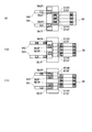
図7〜図10に示すパン片コンベア装置10は、上流コンベア54(第4ベルトコンベア)ではパン片103が1枚ずつ所定間隔で1列に搬送される状態から、下流コンベア58ではパン片103が4列で搬送される状態に変換する。下流コンベア58には4列のトッピング作業ラインが形成される。なお、この実施例では供給ローラコンベアを割愛してある。また、この実施例に用いられる入口コンベア56は先の実施例(図2〜図6)と同等である。   The bread piece conveyor device 10 shown in FIGS. 7 to 10 is configured so that the bread pieces 103 are conveyed in a row at predetermined intervals on the upstream conveyor 54 (fourth belt conveyor), and the bread pieces 103 are provided on the downstream conveyor 58. Is converted into a state of being conveyed in four rows. Four rows of topping work lines are formed on the downstream conveyor 58. In this embodiment, the supply roller conveyor is omitted. Moreover, the entrance conveyor 56 used in this embodiment is equivalent to the previous embodiment (FIGS. 2 to 6).

一方、出口コンベア57は第1〜第4出口コンベア571〜574から構成され、これらの出口コンベア571〜574は前後方向に隣接して設けられている。各出口コンベア571〜574は1枚のパン片103よりやや大きい搬送面を有し、入口コンベア56から2枚ずつパン片103を受け取り、下流側の下流コンベア58に受け渡す。したがって、出口コンベア57全体としては、上流コンベア54と直交する向きにパン片複数枚分(この実施例では4枚分)の長手状並列化スペースを有する幅広のベルトに形成される。また、出口コンベア57は上流コンベア54と交差する方向(図では直交する方向)にシフト移動可能である。以下の記載では、第1〜第4出口コンベア571〜574を包括する場合に出口コンベア57と表す。   On the other hand, the exit conveyor 57 is comprised from the 1st-4th exit conveyors 571-574, and these exit conveyors 571-574 are provided adjacent to the front-back direction. Each of the outlet conveyors 571 to 574 has a conveyance surface that is slightly larger than one bread piece 103, receives the bread pieces 103 from the inlet conveyor 56 two by two, and delivers them to the downstream conveyor 58 on the downstream side. Therefore, the exit conveyor 57 as a whole is formed as a wide belt having a longitudinal parallel space for a plurality of bread pieces (4 sheets in this embodiment) in a direction orthogonal to the upstream conveyor 54. Further, the outlet conveyor 57 can be shifted in a direction intersecting with the upstream conveyor 54 (direction orthogonal in the figure). In the following description, the first to fourth outlet conveyors 571 to 574 are referred to as an outlet conveyor 57 when included.

第1〜第4出口コンベア571〜574の各々は、駆動プーリ57aと2つの従動プーリ57bに掛け回されたベルトコンベアであり、第2駆動装置としての第1〜第4出口コンベアモータ621〜624により、タイミングベルト62a及びタイミングプーリ62bを介し駆動される。従動プーリ57b,57b間の上面が搬送面に形成される。また、第1〜第4出口コンベア571〜574は、空気圧式又は油圧式の出口シフト用シリンダ65(シフト装置)により、一体的に前後方向にシフト可能である。具体的には、出口シフト用シリンダ65の駆動により、フレーム11に前後方向に固定された直線状案内部材65a(通称リニアガイド)に沿って、第1〜第4出口コンベア571〜574の支持フレーム65bが直線移動する。   Each of the first to fourth outlet conveyors 571 to 574 is a belt conveyor wound around a driving pulley 57a and two driven pulleys 57b, and first to fourth outlet conveyor motors 621 to 624 as second driving devices. By this, it is driven via the timing belt 62a and the timing pulley 62b. An upper surface between the driven pulleys 57b and 57b is formed on the transport surface. The first to fourth outlet conveyors 571 to 574 can be integrally shifted in the front-rear direction by a pneumatic or hydraulic outlet shift cylinder 65 (shift device). Specifically, the drive frame of the first to fourth outlet conveyors 571 to 574 is driven along a linear guide member 65a (commonly referred to as a linear guide) fixed to the frame 11 in the front-rear direction by driving the outlet shift cylinder 65. 65b moves linearly.

出口コンベア57の上方に架設された門型形状の出口側フレーム67aには、第1〜第4出口コンベア571〜574の各搬送面におけるパン片103の存否を検出する第1〜第4出口コンベア用光電センサ671〜674(パン片検出手段)が設けられている。   First to fourth outlet conveyors for detecting the presence or absence of the bread pieces 103 on the respective conveying surfaces of the first to fourth outlet conveyors 571 to 574 are arranged on a portal-shaped outlet-side frame 67a installed above the outlet conveyor 57. Photoelectric sensors 671 to 674 (bread piece detecting means) are provided.

光電センサ66F、66R、671〜674の検知信号、コンベアモータ60、61F、61R、621〜624、63及びシリンダ64、65の位置データ等はコントローラ70(コンベア制御装置)に入力される。そして、1列搬送状態から4列搬送状態に変換するための動作指令信号が、コントローラ70からコンベアモータ60、61F、61R、621〜624、63及びシリンダ64、65に出力される。つまり、振分コンベア(入口コンベア56、出口コンベア57)のパン片スペースに対応してパン片103の存否を検出するパン片検出手段(光電センサ66F、66R、671〜674)が設けられ、コンベア制御装置(コントローラ70)は、パン片検出手段の存否検出信号や振分コンベアの駆動装置(コンベアモータ61F、61R、621〜624)及びシフト装置(シリンダ64、65)の位置データに基づいて駆動装置とシフト装置とを制御する。   The detection signals of the photoelectric sensors 66F, 66R, 671-674, the position data of the conveyor motors 60, 61F, 61R, 621-624, 63 and the cylinders 64, 65 are input to the controller 70 (conveyor control device). Then, an operation command signal for converting from the one-row conveyance state to the four-row conveyance state is output from the controller 70 to the conveyor motors 60, 61F, 61R, 621-624, 63 and the cylinders 64, 65. That is, bread piece detecting means (photoelectric sensors 66F, 66R, 671 to 674) for detecting the presence or absence of the bread piece 103 corresponding to the bread piece space of the distribution conveyor (inlet conveyor 56, outlet conveyor 57) are provided. The control device (controller 70) is driven based on the presence / absence detection signal of the bread piece detection means and the position data of the distribution conveyor drive devices (conveyor motors 61F, 61R, 621 to 624) and the shift device (cylinders 64, 65). Control the device and the shift device.

次に、パン片コンベア装置10を用いて1列のパン片を4列に振り分ける手順を、図7〜図10を参照しつつ図11A、図11Bに基づいて説明する。なお、図11A、図11Bの全工程中においても、上流コンベア54(上流コンベアモータ60;図2参照)と下流コンベア58(下流コンベアモータ63;図2参照)とは常時駆動可能である。   Next, a procedure for distributing one row of bread pieces into four rows using the bread piece conveyor device 10 will be described based on FIGS. 11A and 11B with reference to FIGS. 11A and 11B, the upstream conveyor 54 (upstream conveyor motor 60; see FIG. 2) and the downstream conveyor 58 (downstream conveyor motor 63; see FIG. 2) can always be driven.

(1)モータ61Rの駆動により後方側入口コンベア56Rを回転して、上流コンベア54から後方側入口コンベア56Rのスペースにパン片103を受け渡す。光電センサ66Rがパン片103を検知すると直ちに後方側入口コンベア56Rの回転を停止する。この間出口コンベア57は回転を停止している。
(2)シリンダ64の駆動により入口コンベア56を一体的に後方側へシフト移動し、続いてモータ61Fの駆動により前方側入口コンベア56Fを回転して、上流コンベア54から前方側入口コンベア56Fのスペースに次のパン片103を受け渡す。光電センサ66F、66Rがともにパン片103を検知すると直ちに前方側入口コンベア56Fの回転を停止する。この間出口コンベア57は回転を停止している。
(1) The rear entrance conveyor 56R is rotated by driving the motor 61R, and the bread pieces 103 are delivered from the upstream conveyor 54 to the space of the rear entrance conveyor 56R. As soon as the photoelectric sensor 66R detects the bread piece 103, the rotation of the rear entrance conveyor 56R is stopped. During this time, the outlet conveyor 57 stops rotating.
(2) The inlet conveyor 56 is integrally shifted rearward by driving the cylinder 64, and then the front inlet conveyor 56F is rotated by driving the motor 61F, so that the space from the upstream conveyor 54 to the front inlet conveyor 56F. The next bread piece 103 is delivered to. As soon as the photoelectric sensors 66F and 66R detect the bread piece 103, the rotation of the front entrance conveyor 56F is stopped. During this time, the outlet conveyor 57 stops rotating.

(3)モータ61F、61Rの駆動により前方側及び後方側入口コンベア56F、56Rを回転し、さらにモータ623、624の駆動により第3及び第4出口コンベア573、574を回転して、前方側及び後方側入口コンベア56F、56R上のパン片103、103を第3及び第4出口コンベア573、574のスペースに2列状態で受け渡す。光電センサ66F、66Rがともにパン片103を検知しなくなると直ちに前方側及び後方側入口コンベア56F、56Rの回転を停止し、光電センサ673、674がともにパン片103を検知すると直ちに第3及び第4出口コンベア573、574の回転を停止する。   (3) The front and rear inlet conveyors 56F and 56R are rotated by driving the motors 61F and 61R, and the third and fourth outlet conveyors 573 and 574 are rotated by driving the motors 623 and 624. The bread pieces 103 and 103 on the rear-side inlet conveyors 56F and 56R are delivered to the spaces of the third and fourth outlet conveyors 573 and 574 in two rows. As soon as the photoelectric sensors 66F and 66R no longer detect the bread piece 103, the rotation of the front and rear entrance conveyors 56F and 56R is stopped, and as soon as both the photoelectric sensors 673 and 674 detect the bread piece 103, the third and third The rotation of the 4-exit conveyors 573 and 574 is stopped.

(4)シリンダ65の駆動により出口コンベア57を一体的に後方側へシフト移動する。同時に、モータ61Fの駆動により前方側入口コンベア56Fを回転して、上流コンベア54から前方側入口コンベア56Fのスペースに次のパン片103を受け渡す。光電センサ66Fがパン片103を検知すると直ちに前方側入口コンベア56Fの回転を停止する。この間出口コンベア57は回転を停止している。   (4) By driving the cylinder 65, the outlet conveyor 57 is integrally shifted to the rear side. At the same time, the front inlet conveyor 56F is rotated by driving the motor 61F, and the next bread piece 103 is delivered from the upstream conveyor 54 to the space of the front inlet conveyor 56F. As soon as the photoelectric sensor 66F detects the bread piece 103, the rotation of the front entrance conveyor 56F is stopped. During this time, the outlet conveyor 57 stops rotating.

(5)シリンダ64の駆動により入口コンベア56を一体的に前方側へシフト移動し、続いてモータ61Rの駆動により後方側入口コンベア56Rを回転して、上流コンベア54から後方側入口コンベア56Rのスペースに次のパン片103を受け渡す。光電センサ66F、66Rがともにパン片103を検知すると直ちに後方側入口コンベア56Rの回転を停止する。この間出口コンベア57は回転を停止している。   (5) The entrance conveyor 56 is integrally shifted forward by driving the cylinder 64, and then the rear entrance conveyor 56R is rotated by driving the motor 61R, so that the space from the upstream conveyor 54 to the rear entrance conveyor 56R. The next bread piece 103 is delivered to. As soon as the photoelectric sensors 66F and 66R detect the bread piece 103, the rotation of the rear entrance conveyor 56R is stopped. During this time, the outlet conveyor 57 stops rotating.

(6)モータ61F、61Rの駆動により前方側及び後方側入口コンベア56F、56Rを回転し、さらにモータ621、622の駆動により第1及び第2出口コンベア571、572を回転して、前方側及び後方側入口コンベア56F、56R上のパン片103、103を第1及び第2出口コンベア571、572のスペースに2列状態で受け渡す。光電センサ66F、66Rがともにパン片103を検知しなくなると直ちに前方側及び後方側入口コンベア56F、56Rの回転を停止し、光電センサ671、672がともにパン片103を検知すると直ちに第1及び第2出口コンベア571、572の回転を停止する。   (6) The front and rear inlet conveyors 56F and 56R are rotated by driving the motors 61F and 61R, and the first and second outlet conveyors 571 and 572 are further rotated by driving the motors 621 and 622. The bread pieces 103 and 103 on the rear-side inlet conveyors 56F and 56R are transferred to the space of the first and second outlet conveyors 571 and 572 in two rows. As soon as the photoelectric sensors 66F and 66R no longer detect the bread piece 103, the rotation of the front and rear entrance conveyors 56F and 56R is stopped, and as soon as both the photoelectric sensors 671 and 672 detect the bread piece 103, the first and first The rotation of the two outlet conveyors 571 and 572 is stopped.

(7)シリンダ65の駆動により出口コンベア57を一体的に前方側へシフト移動する。同時に、モータ61Rの駆動により後方側入口コンベア56Rを回転して、上流コンベア54から後方側入口コンベア56Rのスペースに次のパン片103を受け渡す。光電センサ66Rがパン片103を検知すると直ちに後方側入口コンベア56Rの回転を停止する。この間出口コンベア57は回転を停止している。
(8)モータ621〜624の駆動により第1〜第4出口コンベア571〜574を回転して、第1〜第4出口コンベア571〜574上のパン片103、103、103、103を下流コンベア58に4列状態で受け渡す。光電センサ671〜674がいずれもパン片103を検知しなくなると直ちに第1〜第4出口コンベア571〜574の回転を停止する。この間入口コンベア56は回転を停止している。
(7) The exit conveyor 57 is integrally shifted forward by driving the cylinder 65. At the same time, the rear inlet conveyor 56R is rotated by driving the motor 61R, and the next bread piece 103 is delivered from the upstream conveyor 54 to the space of the rear inlet conveyor 56R. As soon as the photoelectric sensor 66R detects the bread piece 103, the rotation of the rear entrance conveyor 56R is stopped. During this time, the outlet conveyor 57 stops rotating.
(8) The first to fourth outlet conveyors 571 to 574 are rotated by driving the motors 621 to 624, and the bread pieces 103, 103, 103, 103 on the first to fourth outlet conveyors 571 to 574 are moved to the downstream conveyor 58. Are delivered in a 4-row state. As soon as the photoelectric sensors 671 to 674 no longer detect the bread pieces 103, the rotation of the first to fourth outlet conveyors 571 to 574 is stopped. During this time, the entrance conveyor 56 stops rotating.

以上の手順を繰り返すことにより、上流コンベア54では1列状態のパン片103が下流コンベア58では4列状態に振り分けられる。この実施例では、入口コンベア56、出口コンベア57ともに振り分け機能を有する(シフト移動が可能)ので、短いサイクルタイムで振り分けの列数を増やすことができる。   By repeating the above procedure, the bread pieces 103 in the single row state are distributed to the four rows state in the downstream conveyor 58 by the upstream conveyor 54. In this embodiment, since both the entrance conveyor 56 and the exit conveyor 57 have a sorting function (shifting is possible), the number of sorting columns can be increased in a short cycle time.

なお、第1〜第4出口コンベア571〜574を第1及び第2出口コンベア571、572のグループと第3及び第4出口コンベア573、574のグループとに区分し、2列ずつ駆動搬送する場合には、2列搬送ラインを下流コンベア58上の前方側と後方側とに交互に形成することも可能である。   When the first to fourth outlet conveyors 571 to 574 are divided into a group of first and second outlet conveyors 571 and 572 and a group of third and fourth outlet conveyors 573 and 574, and are driven and conveyed by two rows. It is also possible to alternately form a two-row conveyance line on the front side and the rear side on the downstream conveyor 58.

さらに、図12A〜図12Cは、上流コンベア54での1列搬送状態から、下流コンベア58での3列搬送状態へ変換する手順を示す。なお、この実施例では、図7〜図10に示すパン片コンベア装置10において、下流コンベア58が第1〜第4下流コンベア581〜584として区分され、第1〜第4下流コンベア581〜584は前後方向に隣接して設けられるとともに、それぞれ対応するモータで個別に駆動回転される。また、詳しくは後述するように、上流コンベア54で所定ピッチ毎に搬送されるパン片103が、4ピッチに1回の割合で搬送されない(4回目は空白領域BL)ように調整されている。   Further, FIGS. 12A to 12C show a procedure for converting from the one-row transport state at the upstream conveyor 54 to the three-row transport state at the downstream conveyor 58. In addition, in this Example, in the bread piece conveyor apparatus 10 shown in FIGS. 7-10, the downstream conveyor 58 is divided as the 1st-4th downstream conveyors 581-584, and the 1st-4th downstream conveyors 581-584 are divided. They are provided adjacent to each other in the front-rear direction and are individually driven and rotated by corresponding motors. Further, as will be described in detail later, the bread pieces 103 conveyed at every predetermined pitch by the upstream conveyor 54 are adjusted so as not to be conveyed once every four pitches (the fourth time is a blank area BL).

(1)モータ61Rの駆動により後方側入口コンベア56Rを回転して、上流コンベア54から後方側入口コンベア56Rのスペースにパン片103(1枚目)を受け渡す。光電センサ66Rがパン片103を検知すると直ちに後方側入口コンベア56Rの回転を停止する。この間出口コンベア57は回転を停止している。
(2)シリンダ64の駆動により入口コンベア56を一体的に後方側へシフト移動する。
(3)続いてモータ61Fの駆動により前方側入口コンベア56Fを回転して、上流コンベア54から前方側入口コンベア56Fのスペースに次のパン片103(2枚目)を受け渡す。光電センサ66F、66Rがともにパン片103を検知すると直ちに前方側入口コンベア56Fの回転を停止する。この間出口コンベア57は回転を停止している。
(1) The rear inlet conveyor 56R is rotated by driving the motor 61R, and the bread piece 103 (first sheet) is delivered from the upstream conveyor 54 to the space of the rear inlet conveyor 56R. As soon as the photoelectric sensor 66R detects the bread piece 103, the rotation of the rear entrance conveyor 56R is stopped. During this time, the outlet conveyor 57 stops rotating.
(2) The inlet conveyor 56 is integrally shifted to the rear side by driving the cylinder 64.
(3) Subsequently, the front inlet conveyor 56F is rotated by driving the motor 61F, and the next bread piece 103 (second sheet) is transferred from the upstream conveyor 54 to the space of the front inlet conveyor 56F. As soon as the photoelectric sensors 66F and 66R detect the bread piece 103, the rotation of the front entrance conveyor 56F is stopped. During this time, the outlet conveyor 57 stops rotating.

(4)モータ61F、61Rの駆動により前方側及び後方側入口コンベア56F、56Rを回転し、さらにモータ623、624の駆動により第3及び第4出口コンベア573、574を回転して、前方側及び後方側入口コンベア56F、56R上のパン片103、103を第3及び第4出口コンベア573、574のスペースに2列状態で受け渡す。光電センサ66F、66Rがともにパン片103を検知しなくなると直ちに前方側及び後方側入口コンベア56F、56Rの回転を停止し、光電センサ673、674がともにパン片103を検知すると直ちに第3及び第4出口コンベア573、574の回転を停止する。   (4) The front and rear inlet conveyors 56F and 56R are rotated by driving the motors 61F and 61R, and the third and fourth outlet conveyors 573 and 574 are rotated by driving the motors 623 and 624. The bread pieces 103 and 103 on the rear-side inlet conveyors 56F and 56R are delivered to the spaces of the third and fourth outlet conveyors 573 and 574 in two rows. As soon as the photoelectric sensors 66F and 66R no longer detect the bread piece 103, the rotation of the front and rear entrance conveyors 56F and 56R is stopped, and as soon as both the photoelectric sensors 673 and 674 detect the bread piece 103, the third and third The rotation of the 4-exit conveyors 573 and 574 is stopped.

(5)シリンダ65の駆動により出口コンベア57を一体的に後方側へシフト移動する。同時に、モータ61Fの駆動により前方側入口コンベア56Fを回転して、上流コンベア54から前方側入口コンベア56Fのスペースに次のパン片103(3枚目)を受け渡す。光電センサ66Fがパン片103を検知すると直ちに前方側入口コンベア56Fの回転を停止する。この間出口コンベア57は回転を停止している。   (5) The outlet conveyor 57 is integrally shifted to the rear side by driving the cylinder 65. At the same time, the front inlet conveyor 56F is rotated by driving the motor 61F, and the next bread piece 103 (third sheet) is transferred from the upstream conveyor 54 to the space of the front inlet conveyor 56F. As soon as the photoelectric sensor 66F detects the bread piece 103, the rotation of the front entrance conveyor 56F is stopped. During this time, the outlet conveyor 57 stops rotating.

(6)シリンダ64の駆動により入口コンベア56を一体的に前方側へシフト移動するとともに、シリンダ65の駆動により出口コンベア57を一体的に前方側へシフト移動する。同時にモータ61Fの駆動により前方側入口コンベア56Fを回転し、さらにモータ622の駆動により第2出口コンベア572を回転して、前方側入口コンベア56F上のパン片103を第2出口コンベア572のスペースに1枚だけ受け渡す。これによって、出口コンベア57は合計3枚のパン片103を並列状態で保持することになる。光電センサ66Fがパン片103を検知しなくなると直ちに前方側入口コンベア56Fの回転を停止し、光電センサ672がパン片103を検知すると直ちに第2出口コンベア572の回転を停止する。   (6) The inlet conveyor 56 is integrally shifted forward by driving the cylinder 64, and the outlet conveyor 57 is integrally shifted forward by driving the cylinder 65. At the same time, the front inlet conveyor 56F is rotated by driving the motor 61F, and the second outlet conveyor 572 is rotated by driving the motor 622, so that the bread pieces 103 on the front inlet conveyor 56F become the space of the second outlet conveyor 572. Hand only one piece. As a result, the outlet conveyor 57 holds a total of three bread pieces 103 in a parallel state. As soon as the photoelectric sensor 66F no longer detects the bread piece 103, the rotation of the front entrance conveyor 56F is stopped, and as soon as the photoelectric sensor 672 detects the bread piece 103, the rotation of the second outlet conveyor 572 is stopped.

(7)上記した通り上流コンベア54には4回に1回の割合でパン片103の空白領域BLが設けられているので、このタイミングでは後方側入口コンベア56Rは上流コンベア54から次のパン片103を受け取ることができない。
(8)そこで、シリンダ65の駆動により出口コンベア57を一体的に前方側へシフト移動する。この間入口コンベア56及び出口コンベア57は回転を停止している。
(7) Since the upstream conveyor 54 is provided with the blank area BL of the bread piece 103 at a rate of once every four times as described above, the rear entrance conveyor 56R is moved from the upstream conveyor 54 to the next bread piece at this timing. 103 cannot be received.
(8) Therefore, the outlet conveyor 57 is integrally shifted forward by driving the cylinder 65. During this time, the entrance conveyor 56 and the exit conveyor 57 stop rotating.

(9)モータ621〜623の駆動により第1〜第3出口コンベア571〜573を回転して、第1〜第3出口コンベア571〜573上のパン片103、103、103を下流コンベア581〜583に3列状態で受け渡す。同時に、モータ61Rの駆動により後方側入口コンベア56Rを回転して、上流コンベア54から後方側入口コンベア56Rのスペースに次のパン片103(次の1枚目)を受け渡す。そして、光電センサ671〜673がいずれもパン片103を検知しなくなると直ちに第1〜第3出口コンベア571〜573の回転を停止し、光電センサ66Rがパン片103を検知すると直ちに後方側入口コンベア56Rの回転を停止する。   (9) The first to third outlet conveyors 571 to 573 are rotated by driving the motors 621 to 623, and the bread pieces 103, 103, 103 on the first to third outlet conveyors 571 to 573 are moved to the downstream conveyors 581 to 583. Are delivered in three rows. At the same time, the rear inlet conveyor 56R is rotated by driving the motor 61R, and the next bread piece 103 (next first sheet) is delivered from the upstream conveyor 54 to the space of the rear inlet conveyor 56R. Then, as soon as none of the photoelectric sensors 671 to 673 detect the bread piece 103, the rotation of the first to third outlet conveyors 571 to 573 is stopped, and immediately after the photoelectric sensor 66R detects the bread piece 103, the rear side entrance conveyor. The rotation of 56R is stopped.

(10)シリンダ64の駆動により入口コンベア56を一体的に後方側へシフト移動するとともに、シリンダ65の駆動により出口コンベア57を一体的に後方側へシフト移動する。この間入口コンベア56及び出口コンベア57は回転を停止している。以上の手順を繰り返すことにより、上流コンベア54では1列状態のパン片103が下流コンベア58では前方側(手前側)3列状態に振り分けられる。   (10) The inlet conveyor 56 is integrally shifted to the rear side by driving the cylinder 64, and the outlet conveyor 57 is integrally shifted to the rear side by driving the cylinder 65. During this time, the entrance conveyor 56 and the exit conveyor 57 stop rotating. By repeating the above procedure, the bread pieces 103 in a single row state are distributed to the front side (front side) three rows state in the downstream conveyor 58 by the upstream conveyor 54.

(8’)図12Cでは、上記(6)(7)に続いて、次のパン片103が上流コンベア54の下流端に到着するのを待ち、モータ622〜624の駆動により第2〜第4出口コンベア572〜574を回転して、第2〜第4出口コンベア572〜574上のパン片103、103、103を下流コンベア582〜584に3列状態で受け渡す。同時に、モータ61Rの駆動により後方側入口コンベア56Rを回転して、上流コンベア54から後方側入口コンベア56Rのスペースに次のパン片103(次の1枚目)を受け渡す。そして、光電センサ672〜674がいずれもパン片103を検知しなくなると直ちに第2〜第4出口コンベア572〜574の回転を停止し、光電センサ66Rがパン片103を検知すると直ちに後方側入口コンベア56Rの回転を停止する。以上の手順を繰り返すことにより、上流コンベア54では1列状態のパン片103が下流コンベア58では後方側(奥側)3列状態に振り分けられる。   (8 ′) In FIG. 12C, after the above (6) and (7), it waits for the next bread piece 103 to arrive at the downstream end of the upstream conveyor 54, and then the second to fourth motors 622 to 624 are driven. The outlet conveyors 572 to 574 are rotated to deliver the bread pieces 103, 103, 103 on the second to fourth outlet conveyors 572 to 574 to the downstream conveyors 582 to 584 in three rows. At the same time, the rear inlet conveyor 56R is rotated by driving the motor 61R, and the next bread piece 103 (next first sheet) is delivered from the upstream conveyor 54 to the space of the rear inlet conveyor 56R. Then, as soon as none of the photoelectric sensors 672 to 674 detect the bread piece 103, the rotation of the second to fourth outlet conveyors 572 to 574 is stopped, and immediately after the photoelectric sensor 66R detects the bread piece 103, the rear side entrance conveyor. The rotation of 56R is stopped. By repeating the above procedure, the bread pieces 103 in a single row state are sorted in the rear conveyor (back side) three rows state in the downstream conveyor 58 by the upstream conveyor 54.

1列から2n−1(n:2以上の自然数)の奇数列に振り分ける場合、パン片103は、予め2n回に1回の空白領域BLを設けるように調整して上流コンベア54で搬送される。この実施例では4回に1回の空白領域BLが設けられるので、通常は上流コンベア54で一定距離又は一定時間毎に搬送されるパン片103が、4回に1回の割合で搬送されず、次のパン片103は2倍の距離又は時間を経過して下流端に到着する。なお、図12A〜図12Cの全工程中においても、上流コンベア54と下流コンベア58(第1〜第4下流コンベア581〜584)とは常時駆動可能である。下流コンベア58を第1〜第4下流コンベア581〜584に区分せずに一体で常時駆動してもよい。また、(1)〜(7)→(8)〜(10)の工程と(1)〜(7)→(8’)の工程とを交互に実施することによって、下流コンベア58に前方側3列と後方側3列とをともに形成することができる。   When sorting from one row to 2n-1 (n: a natural number of 2 or more) odd rows, the bread pieces 103 are adjusted in advance so as to provide one blank area BL every 2n times and conveyed by the upstream conveyor 54. . In this embodiment, since the blank area BL is provided once every four times, the bread pieces 103 which are usually conveyed by the upstream conveyor 54 at a certain distance or every certain time are not conveyed at a rate of once every four times. The next bread piece 103 arrives at the downstream end after a double distance or time. In addition, the upstream conveyor 54 and the downstream conveyor 58 (the 1st-4th downstream conveyors 581-584) can be always driven also in all the processes of FIG. 12A-FIG. 12C. The downstream conveyor 58 may be integrally driven at all times without being divided into the first to fourth downstream conveyors 581 to 584. Further, by alternately performing the steps (1) to (7) → (8) to (10) and the steps (1) to (7) → (8 ′), the downstream conveyor 58 has a front side 3. Both the rows and the rear three rows can be formed.

次に、図13A〜図13Cに示すパン片コンベア装置では、上流コンベア54は、第1上流コンベア541及び第2上流コンベア542として前後に平行に設けられるとともに、それぞれ対応するモータで個別に常時駆動回転される。また、入口コンベア56について、第1上流コンベア541に対応する第1入口コンベア561は第1前方入口コンベア561F及び第1後方入口コンベア561Rに区分され、これらは個別に駆動搬送可能かつ一体的にシフト移動可能である。一方、第2上流コンベア542に対応する第2入口コンベア562は第2前方入口コンベア562F及び第2後方入口コンベア562Rに区分され、これらは個別に駆動搬送可能かつ一体的にシフト移動可能である。   Next, in the bread piece conveyor apparatus shown to FIG. 13A-FIG. 13C, while the upstream conveyor 54 is provided in parallel back and forth as the 1st upstream conveyor 541 and the 2nd upstream conveyor 542, it always drives individually with a corresponding motor, respectively. It is rotated. Further, with respect to the entrance conveyor 56, the first entrance conveyor 561 corresponding to the first upstream conveyor 541 is divided into a first front entrance conveyor 561F and a first rear entrance conveyor 561R, which can be individually driven and transported and integrally shifted. It is movable. On the other hand, the second inlet conveyor 562 corresponding to the second upstream conveyor 542 is divided into a second front inlet conveyor 562F and a second rear inlet conveyor 562R, which can be individually driven and transported and can be shifted together.

さらに、出口コンベア57について、第1上流コンベア541に対応する第1出口コンベア571は第1前方出口コンベア571F及び第1後方出口コンベア571Rに区分され、これらは個別に駆動搬送可能かつ一体的にシフト移動可能である。一方、第2上流コンベア542に対応する第2出口コンベア572は第2前方出口コンベア572F及び第2後方出口コンベア572Rに区分され、これらは個別に駆動搬送可能かつ一体的にシフト移動可能である。なお、下流コンベア58は、第1〜第4下流コンベア581〜584として区分され、第1〜第4下流コンベア581〜584は前後方向に隣接して設けられるとともに、それぞれ対応するモータで個別に駆動回転される。   Further, with respect to the outlet conveyor 57, the first outlet conveyor 571 corresponding to the first upstream conveyor 541 is divided into a first front outlet conveyor 571F and a first rear outlet conveyor 571R, which can be individually driven and transported and shifted integrally. It is movable. On the other hand, the second outlet conveyor 572 corresponding to the second upstream conveyor 542 is divided into a second front outlet conveyor 572F and a second rear outlet conveyor 572R, which can be individually driven and conveyed and can be shifted together. The downstream conveyor 58 is divided into first to fourth downstream conveyors 581 to 584, and the first to fourth downstream conveyors 581 to 584 are provided adjacent to each other in the front-rear direction and are individually driven by corresponding motors. It is rotated.

図13A〜図13Cに基づき、第1及び第2上流コンベア541、542による各1列(あわせて2列)の搬送状態から、下流コンベア58での各2列(あわせて4列)の搬送状態へ変換する手順を簡潔に説明する。   Based on FIG. 13A to FIG. 13C, the conveyance state of each of the first and second upstream conveyors 541 and 542 (each of the two rows in total) to the downstream conveyor 58 of each of the two rows (a total of four rows) of the conveyance state The procedure for converting to is described briefly.

(1)第1上流コンベア541のパン片103が第1後方入口コンベア561Rへ受け渡しされ、第2上流コンベア542のパン片103が第2前方入口コンベア562Fへ受け渡しされる。
(2)第1入口コンベア561が後方へシフト移動し、第2入口コンベア562が前方へシフト移動する。
(1) The bread pieces 103 of the first upstream conveyor 541 are delivered to the first rear entrance conveyor 561R, and the bread pieces 103 of the second upstream conveyor 542 are delivered to the second front entrance conveyor 562F.
(2) The first inlet conveyor 561 shifts backward, and the second inlet conveyor 562 shifts forward.

(3)第1上流コンベア541のパン片103が第1前方入口コンベア561Fへ受け渡しされ、第2上流コンベア542のパン片103が第2後方入口コンベア562Rへ受け渡しされる。
(4)第1入口コンベア561のパン片103、103が第1出口コンベア571へ受け渡しされ、第2入口コンベア562のパン片103、103が第2出口コンベア572へ受け渡しされる。
(3) The bread pieces 103 of the first upstream conveyor 541 are delivered to the first front entrance conveyor 561F, and the bread pieces 103 of the second upstream conveyor 542 are delivered to the second rear entrance conveyor 562R.
(4) The bread pieces 103 and 103 of the first inlet conveyor 561 are delivered to the first outlet conveyor 571, and the bread pieces 103 and 103 of the second inlet conveyor 562 are delivered to the second outlet conveyor 572.

(5)第1出口コンベア571が後方へシフト移動し、第2出口コンベア572が前方へシフト移動する。第1上流コンベア541のパン片103が第1前方入口コンベア561Fへ受け渡しされ、第2上流コンベア542のパン片103が第2後方入口コンベア562Rへ受け渡しされる。
(6)第1出口コンベア571及び第2出口コンベア572のパン片が4列搬送状態で下流コンベア58へ受け渡しされる。第1入口コンベア561が前方へシフト移動し、第2入口コンベア562が後方へシフト移動する。
(5) The first outlet conveyor 571 shifts backward, and the second outlet conveyor 572 shifts forward. The bread piece 103 of the first upstream conveyor 541 is delivered to the first front entrance conveyor 561F, and the bread piece 103 of the second upstream conveyor 542 is delivered to the second rear entrance conveyor 562R.
(6) The bread pieces of the first outlet conveyor 571 and the second outlet conveyor 572 are delivered to the downstream conveyor 58 in a four-row transport state. The first inlet conveyor 561 shifts forward and the second inlet conveyor 562 shifts backward.

(7)第1出口コンベア571が前方へシフト移動し、第2出口コンベア572が後方へシフト移動する。第1上流コンベア541のパン片103が第1後方入口コンベア561Rへ受け渡しされ、第2上流コンベア542のパン片103が第2前方入口コンベア562Fへ受け渡しされる。
(8)第1入口コンベア561のパン片103、103が第1出口コンベア571へ受け渡しされ、第2入口コンベア562のパン片103、103が第2出口コンベア572へ受け渡しされる。
(7) The first outlet conveyor 571 shifts forward and the second outlet conveyor 572 shifts backward. The bread piece 103 of the first upstream conveyor 541 is delivered to the first rear entrance conveyor 561R, and the bread piece 103 of the second upstream conveyor 542 is delivered to the second front entrance conveyor 562F.
(8) The bread pieces 103 and 103 of the first inlet conveyor 561 are delivered to the first outlet conveyor 571, and the bread pieces 103 and 103 of the second inlet conveyor 562 are delivered to the second outlet conveyor 572.

(9)第1出口コンベア571が後方へシフト移動し、第2出口コンベア572が前方へシフト移動する。
・第1上流コンベア541のパン片103が第1後方入口コンベア561Rへ受け渡しされ、第2上流コンベア542のパン片103が第2前方入口コンベア562Fへ受け渡しされる。
(10)第1出口コンベア571及び第2出口コンベア572のパン片が4列搬送状態で下流コンベア58へ受け渡しされる。第1入口コンベア561が後方へシフト移動し、第2入口コンベア562が前方へシフト移動する。
(9) The first outlet conveyor 571 shifts backward, and the second outlet conveyor 572 shifts forward.
The bread piece 103 of the first upstream conveyor 541 is delivered to the first rear entrance conveyor 561R, and the bread piece 103 of the second upstream conveyor 542 is delivered to the second front entrance conveyor 562F.
(10) The bread pieces of the first outlet conveyor 571 and the second outlet conveyor 572 are delivered to the downstream conveyor 58 in a four-row transport state. The first entrance conveyor 561 shifts backward and the second entrance conveyor 562 shifts forward.

(11)第1出口コンベア571が前方へシフト移動し、第2出口コンベア572が後方へシフト移動する。第1上流コンベア541のパン片103が第1前方入口コンベア561Fへ受け渡しされ、第2上流コンベア542のパン片103が第2後方入口コンベア562Rへ受け渡しされる。   (11) The first outlet conveyor 571 shifts forward and the second outlet conveyor 572 shifts backward. The bread piece 103 of the first upstream conveyor 541 is delivered to the first front entrance conveyor 561F, and the bread piece 103 of the second upstream conveyor 542 is delivered to the second rear entrance conveyor 562R.

(11)から(4)に戻り、以上の手順を繰り返すことにより、第1及び第2上流コンベア541、542では各1列(あわせて2列)状態のパン片103が下流コンベア58では各2列(あわせて4列)状態に振り分けられる。このように、上流コンベア、入口コンベア、出口コンベアをセットにして複数組(この実施例では2組)を並列的に作動させることにより、入口コンベア、出口コンベアの待機時間、ひいてはサイクルタイムを短縮でき、振り分け形態の自由度も大きくなる。なお、図13A〜図13Cの全工程中においても、上流コンベア54(第1及び第2上流コンベア541、542)と下流コンベア58(第1〜第4下流コンベア581〜584)とは常時駆動可能である。下流コンベア58を第1〜第4下流コンベア581〜584に区分せずに一体で常時駆動してもよい。第1及び第2出口コンベア571、572は、前後に区分せずに各々1個のベルトコンベアで構成してもよい。   By returning from (11) to (4) and repeating the above procedure, each of the first and second upstream conveyors 541 and 542 has two rows of bread pieces 103 in the downstream conveyor 58. Sorted into row (4 rows in total) status. In this way, by waiting for the upstream conveyor, the entrance conveyor, and the exit conveyor to operate in parallel (two sets in this embodiment), the standby time for the entrance conveyor and the exit conveyor, and thus the cycle time, can be shortened. , The degree of freedom of the distribution form is also increased. 13A to 13C, the upstream conveyor 54 (first and second upstream conveyors 541 and 542) and the downstream conveyor 58 (first to fourth downstream conveyors 581 to 584) can be driven at all times. It is. The downstream conveyor 58 may be integrally driven at all times without being divided into the first to fourth downstream conveyors 581 to 584. The first and second outlet conveyors 571 and 572 may each be constituted by one belt conveyor without being divided into front and rear.

以上の説明では、バター塗布工程とトッピング工程との間で1列から複数列への変換を1回のみ実施したが、複数列への変換時期はバター塗布工程前であっても他の工程の前後いずれであってもよく、また変換を複数回行ってもよい。また、図1はパン塊のスライス装置や耳落とし装置の一例であり、所定の厚さにスライスされたパン片が下流に搬送されればよいから、スライスや耳落としの構造や方法は任意であり、耳部を落とさないパン片に本発明を適用してもよい。パン片を複数列にする目的も問わず、トッピング作業に限るものではない。スライス工程、耳落とし工程等を含む一貫処理の中で振り分けを行っているが、スライス工程や耳落とし工程で集めたパン片を改めて搬送する過程で振り分けを行ってもよい。   In the above description, the conversion from one row to a plurality of rows was performed only once between the butter coating step and the topping step. However, the conversion time to the plurality of rows is different from that of the other steps even before the butter coating step. Either before or after, and conversion may be performed a plurality of times. Further, FIG. 1 is an example of a bread lump slicing device or ear drop device, and it is sufficient that a bread piece sliced to a predetermined thickness is conveyed downstream, so the structure and method of slicing and ear drop are arbitrary. The present invention may be applied to a bread piece that does not drop the ear. The purpose of making the bread pieces into a plurality of rows is not limited to topping work. Although the sorting is performed in an integrated process including a slicing process, an ear dropping process, and the like, the sorting may be performed in the process of transporting the bread pieces collected in the slicing process or the ear dropping process.

なお、図7〜図11Bに示す実施例、図12A〜図12Cに示す実施例及び図13A〜図13Cに示す実施例において、図1〜図6に示す実施例と共通の機能を有する部位には同一符号を付して詳細な説明を省略している。また、上記各実施例は、技術的な矛盾を生じない範囲において適宜組み合わせて実施できる。   In the embodiment shown in FIGS. 7 to 11B, the embodiment shown in FIGS. 12A to 12C, and the embodiment shown in FIGS. 13A to 13C, the parts having the same functions as those of the embodiment shown in FIGS. Are denoted by the same reference numerals and detailed description thereof is omitted. Further, the above embodiments can be appropriately combined and implemented within a range that does not cause technical contradiction.

10 パン片コンベア装置
54 上流コンベア
56 入口コンベア(振分コンベア)
56F、56R 前方側、後方側入口コンベア
57 出口コンベア(振分コンベア)
57F、57R 前方側、後方側出口コンベア
571〜574 第1〜第4出口コンベア
58 下流コンベア
60 上流コンベアモータ(第1駆動装置)
61F、61R 前方側、後方側入口コンベアモータ(第2駆動装置)
62 出口コンベアモータ(第2駆動装置)
62F、62R 前方側、後方側出口コンベアモータ(第2駆動装置)
621〜624 第1〜第4出口コンベアモータ(第2駆動装置)
63 下流コンベアモータ(第3駆動装置)
64 入口シフト用シリンダ(シフト装置)
65 出口シフト用シリンダ(シフト装置)
70 コントローラ(コンベア制御装置)
103 パン片
10 Bread piece conveyor device 54 Upstream conveyor 56 Entrance conveyor (sorting conveyor)
56F, 56R Front side, rear side entrance conveyor 57 Exit conveyor (sorting conveyor)
57F, 57R Front side, rear side outlet conveyors 571-574 First to fourth outlet conveyors 58 Downstream conveyor 60 Upstream conveyor motor (first drive unit)
61F, 61R Front side, rear side entrance conveyor motor (second drive unit)
62 Exit conveyor motor (second drive unit)
62F, 62R Front side, rear side exit conveyor motor (second drive unit)
621-624 1st-4th exit conveyor motor (2nd drive device)
63 Downstream conveyor motor (third drive)
64 Inlet shift cylinder (shift device)
65 Cylinder for outlet shift (shift device)
70 Controller (Conveyor control device)
103 bread pieces

Claims (3)

パン塊からスライスした1枚ずつのパン片を所定間隔で1列にして下流へ送る上流ベルトコンベアと、
その上流ベルトコンベアの下流側に接続され、該上流ベルトコンベアと交差する方向であるシフト方向にシフト可能に設けられ、かつ更に下流側へ前記パン片を複数並列に変換して送り出す振分装置と、
その振分装置の下流側へ接続され、該振分装置から複数並列状態で受け取ったパン片を下流側へ複数列のパン片として移動させる下流ベルトコンベアと、を含み、
前記振分装置は、前記上流ベルトコンベアに対し前記シフト方向に沿って並列状態となるように配置された複数の振分ベルトコンベアを全体が一体的にシフト可能に備えるとともに、
その複数設けられた個々の振分ベルトコンベアは、上流から搬送されるパン片のスライス面を受けるための複数のパン片スペースにそれぞれ対応して位置し、
前記複数の振分ベルトコンベアのうち上流からのパン片を前記パン片スペースで受け取るものだけ個別に駆動、かつ複数の振分ベルトコンベアが前記シフト方向に一体的にシフトする動作を伴ってパン片を複数並列させ、そのパン片を下流側へ送り出す動作を繰り返すコンベア制御装置を備えることを特徴とするパン片コンベア装置。
An upstream belt conveyor that sends each piece of bread sliced from a loaf of bread in a row at a predetermined interval to the downstream;
A distribution device connected to the downstream side of the upstream belt conveyor, provided so as to be capable of shifting in a shift direction that intersects with the upstream belt conveyor, and further converting the bread pieces to a downstream side in parallel and sending them out; ,
A downstream belt conveyor connected to the downstream side of the sorting device and moving a plurality of bread pieces received in parallel from the sorting device to the downstream side as a plurality of rows of bread pieces,
The sorting apparatus includes a plurality of sorting belt conveyors arranged so as to be in parallel with the upstream belt conveyor along the shift direction, and the entire sorting apparatus can be integrally shifted, and
Each of the plurality of sorting belt conveyors provided is positioned corresponding to each of a plurality of bread piece spaces for receiving a slice surface of a bread piece conveyed from upstream,
With the operation of the shift integrally bread pieces the only ones to receive bread pieces spaces driven individually, and a plurality of sorting belt conveyors are the shift direction from the upstream of the plurality of sorting belt conveyors A bread piece conveyor apparatus comprising a conveyor control device that repeats an operation of arranging a plurality of bread pieces in parallel and sending the bread pieces downstream.
前記コンベア制御装置は、前記上流ベルトコンベア、前記振分ベルトコンベア及び前記下流ベルトコンベアの作動を制御するものであって、前記複数の振分ベルトコンベアのうち前記上流ベルトコンベアからパン片を受け取るために必要なものを駆動して、パン片の受渡しを行わせ、前記複数の振分ベルトコンベアを一体的に前記シフト方向へシフトさせて次のパン片を並列的に受け入れるパン片スペースを他の振分ベルトコンベア上に作るとともに、前記他の振分ベルトコンベアを駆動して、前記上流ベルトコンベアから前記他の振分ベルトコンベアに次のパン片を受け渡し、前記複数の振分ベルトコンベア上に設定数のパン片が並列的に載置された後、それら複数の振分ベルトコンベアを一斉に駆動して並列した複数のパン片を下流側へ送り出す動作を繰り返す請求項1に記載のパン片コンベア装置。 The conveyor control device controls operations of the upstream belt conveyor, the sorting belt conveyor, and the downstream belt conveyor, and receives a bread piece from the upstream belt conveyor among the plurality of sorting belt conveyors. To drive the necessary pieces, to transfer the bread pieces, shift the plurality of sorting belt conveyors integrally in the shifting direction, and to receive the next bread piece in parallel It is made on the sorting belt conveyor, and the other sorting belt conveyor is driven, and the next bread piece is transferred from the upstream belt conveyor to the other sorting belt conveyor. After the set number of bread pieces are placed in parallel, the plurality of sorting belt conveyors are driven all at once, and the plurality of parallel bread pieces are moved downstream. Bread piece conveyor according to claim 1 to repeat the operation to issue Ri. 前記振分装置は、前記上流ベルトコンベアの下流側に位置する、前記複数の振分ベルトコンベアを有する入口コンベアと、その入口コンベアの更に下流側に位置する、前記複数の振分ベルトコンベアを有する出口コンベアとを備え、それら入口コンベアと出口コンベアとはパン片の受渡しが可能なように隣接し、かつ互いに独立して前記上流ベルトコンベアと交差する方向にシフト可能であり、
前記入口コンベアのシフトによりパン片が複数並列し、これが前記出口コンベアに受け渡され、その出口コンベアは前記入口コンベアのパン片の並列数を更に増加するようにシフトしてパン片を保持し、又は前記入口コンベアからの並列数のパン片をそのまま保持して、更に前記下流ベルトコンベアに複数並列したパン片を受け渡し、前記入口コンベアは前記出口コンベアが所定並列数のパン片を前記下流ベルトコンベアに受け渡す間に新たなパン片を前記上流ベルトコンベアから受け取り、自身のシフトにより並列化して前記出口コンベアに受け渡す行程に備え、このような全体の動作が前記コンベア制御装置の制御により実行される請求項1に記載のパン片コンベア装置。
The sorting apparatus has an inlet conveyor having the plurality of sorting belt conveyors located on the downstream side of the upstream belt conveyor , and the plurality of sorting belt conveyors located further on the downstream side of the inlet conveyor. An exit conveyor, the entrance conveyor and the exit conveyor are adjacent to each other so that a bread piece can be delivered, and can be shifted in a direction intersecting the upstream belt conveyor independently of each other;
A plurality of bread pieces are arranged in parallel by the shift of the entrance conveyor, and this is transferred to the exit conveyor, and the exit conveyor is shifted so as to further increase the parallel number of bread pieces of the entrance conveyor to hold the bread pieces, or the number of parallel bread pieces from the inlet conveyor it holds, further the downstream transferring multiple parallel bread pieces on the belt conveyor, the inlet conveyor is the downstream belt conveyor pan piece of said outlet conveyors predetermined number of parallel A new piece of bread is received from the upstream belt conveyor during delivery to the outlet conveyor, prepared in parallel with the shift of its own, and delivered to the outlet conveyor. Such an overall operation is executed under the control of the conveyor control device. The bread piece conveyor apparatus according to claim 1.
JP2012029859A 2012-02-14 2012-02-14 Bread piece conveyor Active JP5130552B1 (en)

Priority Applications (1)

Application Number Priority Date Filing Date Title
JP2012029859A JP5130552B1 (en) 2012-02-14 2012-02-14 Bread piece conveyor

Applications Claiming Priority (1)

Application Number Priority Date Filing Date Title
JP2012029859A JP5130552B1 (en) 2012-02-14 2012-02-14 Bread piece conveyor

Publications (2)

Publication Number Publication Date
JP5130552B1 true JP5130552B1 (en) 2013-01-30
JP2013166613A JP2013166613A (en) 2013-08-29

Family

ID=47693014

Family Applications (1)

Application Number Title Priority Date Filing Date
JP2012029859A Active JP5130552B1 (en) 2012-02-14 2012-02-14 Bread piece conveyor

Country Status (1)

Country Link
JP (1) JP5130552B1 (en)

Families Citing this family (1)

* Cited by examiner, † Cited by third party
Publication number Priority date Publication date Assignee Title
JP7716082B2 (en) * 2021-04-23 2025-07-31 古河工業株式会社 Transfer and transportation system

Citations (5)

* Cited by examiner, † Cited by third party
Publication number Priority date Publication date Assignee Title
JPS4911820Y1 (en) * 1970-07-29 1974-03-22
JPS6124247B2 (en) * 1980-03-17 1986-06-10 Toyo Shokuhin Kikai Kk
JPH0385583U (en) * 1989-12-20 1991-08-29
JPH08363A (en) * 1994-06-17 1996-01-09 Shinko Electric Co Ltd Tray loading device
JP2008260567A (en) * 2007-04-13 2008-10-30 Daisey Machinery Co Ltd Packaging device for sliced white bread

Patent Citations (5)

* Cited by examiner, † Cited by third party
Publication number Priority date Publication date Assignee Title
JPS4911820Y1 (en) * 1970-07-29 1974-03-22
JPS6124247B2 (en) * 1980-03-17 1986-06-10 Toyo Shokuhin Kikai Kk
JPH0385583U (en) * 1989-12-20 1991-08-29
JPH08363A (en) * 1994-06-17 1996-01-09 Shinko Electric Co Ltd Tray loading device
JP2008260567A (en) * 2007-04-13 2008-10-30 Daisey Machinery Co Ltd Packaging device for sliced white bread

Also Published As

Publication number Publication date
JP2013166613A (en) 2013-08-29

Similar Documents

Publication Publication Date Title
US11554887B2 (en) Conveyor device for conveying food products
US8910457B2 (en) Apparatus and method for cutting slices of a food product and loading them on a conveying surface, and treatment plant including said apparatus
KR101653870B1 (en) Egg conveying apparatus and egg transfer method
US8113336B2 (en) Automated manipulator system to separate bundles, and method for the operation thereof
US7717251B2 (en) Apparatus for the conveying of separated goods
US20120042612A1 (en) Conveying of articles
US7104388B2 (en) Conveyor system for stacked product
US20070017780A1 (en) Transfer and distribution conveyor system
JP5130552B1 (en) Bread piece conveyor
EP1935788A1 (en) Means for transferring foodstuffs in machines
KR101828738B1 (en) Counting device for automatic seasoned laver Processing line
US20120017538A1 (en) Modular unit for automatic packaging of food products to be packaged in trays
GB1587715A (en) Article handling apparatus
JP5232111B2 (en) Article supply device
CN102730228A (en) Method for automatically on-line combining foodstuff in production line in more than one column into single-row foodstuff
CN105849015A (en) Method and device for conveying and grouping fragmented products
WO2020026184A1 (en) Device for feeding solid food products
JP6286159B2 (en) Alignment method and apparatus
JP5759327B2 (en) Bread bread conveying method and apparatus in bread slicer
JP2007091395A (en) Alignment device
JP2015227222A (en) Article transfer method and device therefor
JP6997848B1 (en) Food transport equipment
EP1666360B1 (en) Method and unit for the formation of groups of products in a machine for the continuous packaging of products
JP2007131373A (en) Article feeder of packaging machine

Legal Events

Date Code Title Description
TRDD Decision of grant or rejection written
A01 Written decision to grant a patent or to grant a registration (utility model)

Free format text: JAPANESE INTERMEDIATE CODE: A01

A61 First payment of annual fees (during grant procedure)

Free format text: JAPANESE INTERMEDIATE CODE: A61

Effective date: 20121015

FPAY Renewal fee payment (event date is renewal date of database)

Free format text: PAYMENT UNTIL: 20151116

Year of fee payment: 3

R150 Certificate of patent or registration of utility model

Ref document number: 5130552

Country of ref document: JP

Free format text: JAPANESE INTERMEDIATE CODE: R150

Free format text: JAPANESE INTERMEDIATE CODE: R150

R250 Receipt of annual fees

Free format text: JAPANESE INTERMEDIATE CODE: R250

R250 Receipt of annual fees

Free format text: JAPANESE INTERMEDIATE CODE: R250

R250 Receipt of annual fees

Free format text: JAPANESE INTERMEDIATE CODE: R250

R250 Receipt of annual fees

Free format text: JAPANESE INTERMEDIATE CODE: R250

R250 Receipt of annual fees

Free format text: JAPANESE INTERMEDIATE CODE: R250

R250 Receipt of annual fees

Free format text: JAPANESE INTERMEDIATE CODE: R250

R250 Receipt of annual fees

Free format text: JAPANESE INTERMEDIATE CODE: R250

R250 Receipt of annual fees

Free format text: JAPANESE INTERMEDIATE CODE: R250

R250 Receipt of annual fees

Free format text: JAPANESE INTERMEDIATE CODE: R250

R250 Receipt of annual fees

Free format text: JAPANESE INTERMEDIATE CODE: R250

R250 Receipt of annual fees

Free format text: JAPANESE INTERMEDIATE CODE: R250