JP5128789B2 - Fuel cell stack - Google Patents
Fuel cell stack Download PDFInfo
- Publication number
- JP5128789B2 JP5128789B2 JP2006199566A JP2006199566A JP5128789B2 JP 5128789 B2 JP5128789 B2 JP 5128789B2 JP 2006199566 A JP2006199566 A JP 2006199566A JP 2006199566 A JP2006199566 A JP 2006199566A JP 5128789 B2 JP5128789 B2 JP 5128789B2
- Authority
- JP
- Japan
- Prior art keywords
- separator
- fuel cell
- cell stack
- load receiving
- electrode structure
- Prior art date
- Legal status (The legal status is an assumption and is not a legal conclusion. Google has not performed a legal analysis and makes no representation as to the accuracy of the status listed.)
- Active
Links
Images


Classifications
-
- H—ELECTRICITY
- H01—ELECTRIC ELEMENTS
- H01M—PROCESSES OR MEANS, e.g. BATTERIES, FOR THE DIRECT CONVERSION OF CHEMICAL ENERGY INTO ELECTRICAL ENERGY
- H01M8/00—Fuel cells; Manufacture thereof
- H01M8/24—Grouping of fuel cells, e.g. stacking of fuel cells
- H01M8/2465—Details of groupings of fuel cells
- H01M8/247—Arrangements for tightening a stack, for accommodation of a stack in a tank or for assembling different tanks
- H01M8/248—Means for compression of the fuel cell stacks
-
- H—ELECTRICITY
- H01—ELECTRIC ELEMENTS
- H01M—PROCESSES OR MEANS, e.g. BATTERIES, FOR THE DIRECT CONVERSION OF CHEMICAL ENERGY INTO ELECTRICAL ENERGY
- H01M8/00—Fuel cells; Manufacture thereof
- H01M8/24—Grouping of fuel cells, e.g. stacking of fuel cells
- H01M8/2465—Details of groupings of fuel cells
- H01M8/247—Arrangements for tightening a stack, for accommodation of a stack in a tank or for assembling different tanks
- H01M8/2475—Enclosures, casings or containers of fuel cell stacks
-
- H—ELECTRICITY
- H01—ELECTRIC ELEMENTS
- H01M—PROCESSES OR MEANS, e.g. BATTERIES, FOR THE DIRECT CONVERSION OF CHEMICAL ENERGY INTO ELECTRICAL ENERGY
- H01M8/00—Fuel cells; Manufacture thereof
- H01M8/10—Fuel cells with solid electrolytes
- H01M2008/1095—Fuel cells with polymeric electrolytes
-
- Y—GENERAL TAGGING OF NEW TECHNOLOGICAL DEVELOPMENTS; GENERAL TAGGING OF CROSS-SECTIONAL TECHNOLOGIES SPANNING OVER SEVERAL SECTIONS OF THE IPC; TECHNICAL SUBJECTS COVERED BY FORMER USPC CROSS-REFERENCE ART COLLECTIONS [XRACs] AND DIGESTS
- Y02—TECHNOLOGIES OR APPLICATIONS FOR MITIGATION OR ADAPTATION AGAINST CLIMATE CHANGE
- Y02E—REDUCTION OF GREENHOUSE GAS [GHG] EMISSIONS, RELATED TO ENERGY GENERATION, TRANSMISSION OR DISTRIBUTION
- Y02E60/00—Enabling technologies; Technologies with a potential or indirect contribution to GHG emissions mitigation
- Y02E60/30—Hydrogen technology
- Y02E60/50—Fuel cells
Description
本発明は、電解質の両側に一対の電極を設けた電解質・電極構造体とセパレータとを備える燃料電池が積層される燃料電池スタックに関する。 The present invention relates to a fuel cell stack in which a fuel cell including an electrolyte / electrode structure provided with a pair of electrodes on both sides of an electrolyte and a separator is stacked.
例えば、固体高分子型燃料電池は、高分子イオン交換膜からなる固体高分子電解質膜の両側に、それぞれアノード側電極及びカソード側電極を配設した電解質膜・電極構造体(電解質・電極構造体)を、セパレータによって挟持して構成されている。 For example, a polymer electrolyte fuel cell has an electrolyte membrane / electrode structure (electrolyte / electrode structure) in which an anode side electrode and a cathode side electrode are disposed on both sides of a solid polymer electrolyte membrane made of a polymer ion exchange membrane, respectively. ) Is sandwiched between separators.
この種の燃料電池では、通常、数十〜数百の燃料電池を積層して燃料電池スタックを構成している。その際、燃料電池自体及び前記燃料電池同士を正確に位置決めする必要があり、例えば、特許文献1に開示された燃料電池が知られている。 In this type of fuel cell, several tens to several hundreds of fuel cells are usually stacked to form a fuel cell stack. At that time, the fuel cell itself and the fuel cells need to be accurately positioned. For example, a fuel cell disclosed in Patent Document 1 is known.
この燃料電池は、電解質の両側に一対の電極を設けた電解質・電極構造体を、第1及び第2セパレータで挟持して構成される燃料電池であって、前記第1及び第2セパレータは、第1及び第2位置決め用孔部を設け、前記第1及び第2位置決め用孔部に、第1及び第2絶縁性位置決め部材が装着されるとともに、前記第1絶縁性位置決め部材の内周壁部に、前記第2絶縁性位置決め部材の外周壁部が嵌合することにより、前記第1及び第2セパレータ同士が絶縁状態で位置決めされる。 This fuel cell is a fuel cell configured by sandwiching an electrolyte / electrode structure provided with a pair of electrodes on both sides of an electrolyte between first and second separators, wherein the first and second separators are: First and second positioning holes are provided, and first and second insulating positioning members are mounted in the first and second positioning holes, and an inner peripheral wall portion of the first insulating positioning member Further, when the outer peripheral wall portion of the second insulating positioning member is fitted, the first and second separators are positioned in an insulated state.
また、特許文献2には、電解質の両側に一対の電極を設ける電解質・電極構造体を、第1及び第2セパレータで挟持する単位セルを備える燃料電池であって、前記第1及び第2セパレータの外周を、複数個所で保持する複数の金属クリップ部材を備え、前記金属クリップ部材は、側板部と、前記側板部の端部で屈曲して前記第1及び第2セパレータの外周を把持する第1及び第2舌片部とを有し、前記第1及び第2舌片部は、前記側板部よりも長尺に構成されるとともに、ばね性を備えることを特徴とする燃料電池が開示されている。 Further, Patent Document 2 discloses a fuel cell including a unit cell that sandwiches an electrolyte / electrode structure having a pair of electrodes on both sides of an electrolyte with a first and a second separator, and the first and second separators. A plurality of metal clip members for holding the outer periphery of the first and second separators by bending at a side plate portion and an end portion of the side plate portion. 1 and a second tongue piece portion, and the first and second tongue piece portions are configured to be longer than the side plate portion and have a spring property. ing.
ところで、燃料電池スタックは、燃料電池の積層方向に延在するタイロッドを介して前記積層方向に締め付け荷重を付与する構造の他、積層された燃料電池をボックス状のケーシング内に収容して前記積層方向に締め付け荷重を付与する構造等が採用されており、通常、車載用として各種車両に搭載されている。 Incidentally, the fuel cell stack has a structure in which a clamping load is applied in the stacking direction via a tie rod extending in the stacking direction of the fuel cells, and the stacked fuel cells are accommodated in a box-shaped casing and the stacking is performed. A structure or the like that applies a tightening load in the direction is employed, and it is usually mounted on various vehicles for in-vehicle use.
その際、車両の衝突時に、例えば、ケーシングが変形してセパレータに接触すると、前記ケーシングを介して前記セパレータが短絡したり、前記セパレータが変形して燃料電池内のシール性が低下したりするという問題がある。 At that time, for example, when the casing is deformed and contacts the separator at the time of a vehicle collision, the separator is short-circuited through the casing, or the separator is deformed and the sealing performance in the fuel cell is lowered. There's a problem.
本発明はこの種の問題を解決するものであり、外部からの荷重に対して、セパレータの変形によるシール性の低下や前記セパレータの短絡を確実に阻止することが可能な燃料電池スタックを提供することを目的とする。 The present invention solves this type of problem, and provides a fuel cell stack capable of reliably preventing a decrease in sealing performance due to deformation of a separator and a short circuit of the separator against an external load. For the purpose.
本発明は、電解質の両側に一対の電極を設けた電解質・電極構造体とセパレータとを備える燃料電池が積層されるとともに、ケーシング内に収容される燃料電池スタックに関するものである。この燃料電池スタックは、複数のセパレータを積層方向に一体に保持する接続部材と、前記接続部材により一体に保持される前記セパレータの中、少なくとも1つのセパレータの外周部に設けられ、他のセパレータの外周部より外方に突出して外部からの荷重を受けるための樹脂製ガイド部とを備え、前記樹脂製ガイド部には、前記接続部材である絶縁性クリップを挿入するための孔部が積層方向に形成されている。 The present invention relates to a fuel cell stack in which a fuel cell including an electrolyte / electrode structure provided with a pair of electrodes on both sides of an electrolyte and a separator is stacked and accommodated in a casing . The fuel cell stack is provided on an outer peripheral portion of at least one separator among the connection member that integrally holds a plurality of separators in the stacking direction and the separator that is integrally held by the connection member. A resin guide portion that protrudes outward from the outer peripheral portion and receives a load from the outside, and the resin guide portion has a hole portion for inserting an insulating clip as the connection member in the stacking direction Is formed .
さらに、絶縁性クリップは、略円柱状を有するとともに、軸方向に延在してスリットが形成されることが好ましい。 Furthermore, it is preferable that the insulating clip has a substantially cylindrical shape and extends in the axial direction to form a slit.
本発明によれば、燃料電池の積層方向に交差する方向から外部荷重が付与されると、少なくとも1つのセパレータの外周部に外方に突出して設けられている樹脂製ガイド部が、前記外部荷重を受ける。その際、複数のセパレータは、接続部材により一体に保持されており、樹脂製ガイド部に付与された外部荷重が、前記接続部材を介して前記複数のセパレータに分散される。 According to the present invention, when an external load is applied from a direction that intersects the stacking direction of the fuel cells, the resin guide portion that protrudes outwardly from the outer peripheral portion of at least one separator includes the external load. Receive. At that time, the plurality of separators are integrally held by the connection member, and an external load applied to the resin guide portion is dispersed to the plurality of separators via the connection member.
これにより、燃料電池自体のずれによるシール性の低下を良好に阻止することができ、しかもセパレータの短絡が惹起することがない。さらに、燃料電池の組み立て時には、少なくとも1つのセパレータの外周部に設けられている樹脂製ガイド部が組み立てガイド上を摺動するため、全てのセパレータを摺動させる場合に比べ、摺動抵抗が低減されて組み立て作業が容易に遂行可能になる。 As a result, it is possible to satisfactorily prevent deterioration of the sealing performance due to the deviation of the fuel cell itself, and the short circuit of the separator does not occur. In addition, when assembling the fuel cell, the resin guide provided on the outer periphery of at least one separator slides on the assembly guide, reducing sliding resistance compared to sliding all separators. As a result, the assembly work can be easily performed.
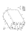
図1は、本発明の第1の実施形態に係る燃料電池スタック10の概略斜視説明図である。
FIG. 1 is a schematic perspective explanatory view of a
燃料電池スタック10は、複数の燃料電池ユニット12を矢印A方向に積層してケーシング14内に収容している。ケーシング14は、燃料電池ユニット12の積層方向両端に配置されるエンドプレート16a、16bと、前記燃料電池ユニット12の側部に配置される4枚の側部プレート18a〜18dと、前記エンドプレート16a、16b及び前記側部プレート18a〜18dを互いに連結するヒンジ機構20とを備える。
The
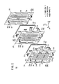
図2に示すように、燃料電池ユニット12は、少なくとも第1電解質膜(電解質)・電極構造体22a及び第2電解質膜・電極構造体22bと、少なくとも第1セパレータ24、第2セパレータ26及び第3セパレータ28とを設ける。第1セパレータ24及び第2セパレータ26の間で第1電解質膜・電極構造体22aを挟持する一方、前記第2セパレータ26及び第3セパレータ28の間で第2電解質膜・電極構造体22bを挟持する。第1セパレータ24〜第3セパレータ28は、金属セパレータで構成されているが、例えば、カーボンセパレータを採用してもよい。
As shown in FIG. 2, the
燃料電池ユニット12の長辺方向(図2中、矢印C方向)の一端縁部(上端縁部)には、矢印A方向に互いに連通して、酸化剤ガス、例えば、酸素含有ガスを供給するための酸化剤ガス入口連通孔30aと、燃料ガス、例えば、水素含有ガスを供給するための燃料ガス入口連通孔32aとが設けられる。
An oxidant gas, for example, an oxygen-containing gas is supplied to one end edge (upper edge) in the long side direction (the arrow C direction in FIG. 2) of the
燃料電池ユニット12の長辺方向の他端縁部(下端縁部)には、矢印A方向に互いに連通して、燃料ガスを排出するための燃料ガス出口連通孔32bと、酸化剤ガスを排出するための酸化剤ガス出口連通孔30bとが設けられる。
The other end edge (lower end edge) of the long side direction of the
燃料電池ユニット12の短辺方向(矢印B方向)の一端縁部には、冷却媒体を供給するための2つの冷却媒体入口連通孔34aが設けられるとともに、前記燃料電池ユニット12の短辺方向の他端縁部には、冷却媒体を排出するための2つの冷却媒体出口連通孔34bが設けられる。
Two cooling medium
第1電解質膜・電極構造体22a及び第2電解質膜・電極構造体22bは、例えば、パーフルオロスルホン酸の薄膜に水が含浸された固体高分子電解質膜36と、前記固体高分子電解質膜36を挟持するアノード側電極38及びカソード側電極40とを備える。
The first electrolyte membrane /
アノード側電極38及びカソード側電極40は、カーボンペーパ等からなるガス拡散層(図示せず)と、白金合金が表面に担持された多孔質カーボン粒子が前記ガス拡散層の表面に一様に塗布されて形成される電極触媒層(図示せず)とを有する。電極触媒層は、固体高分子電解質膜36の両面に形成される。
The
第1セパレータ24の第1電解質膜・電極構造体22aに向かう面24aには、燃料ガス入口連通孔32aと燃料ガス出口連通孔32bとを連通する第1燃料ガス流路42が形成される。この第1燃料ガス流路42は、例えば、矢印C方向に延在する複数の溝部により構成される。第1セパレータ24の面24bには、冷却媒体入口連通孔34aと冷却媒体出口連通孔34bとを連通する冷却媒体流路44が形成される。この冷却媒体流路44は、矢印B方向に延在する複数の溝部により構成される。
A first fuel
第2セパレータ26の第1電解質膜・電極構造体22aに向かう面26aには、例えば、矢印C方向に延在する複数の溝部からなる第1酸化剤ガス流路46が設けられるとともに、この第1酸化剤ガス流路46は、酸化剤ガス入口連通孔30aと酸化剤ガス出口連通孔30bとに連通する。第2セパレータ26の第2電解質膜・電極構造体22bに向かう面26bには、燃料ガス入口連通孔32aと燃料ガス出口連通孔32bとを連通する第2燃料ガス流路48が形成される。
The
第3セパレータ28の第2電解質膜・電極構造体22bに向かう面28aには、酸化剤ガス入口連通孔30aと酸化剤ガス出口連通孔30bと連通する第2酸化剤ガス流路50が設けられる。第3セパレータ28の面28bには、第1セパレータ24の面24bと重なり合って冷却媒体流路44が一体的に形成される。
A second oxidant
第1セパレータ24の面24a、24bには、この第1セパレータ24の外周端縁部を周回して第1シール部材52が一体成形される。第2セパレータ26の面26a、26bには、この第2セパレータ26の外周端縁部を周回して第2シール部材54が一体成形されるとともに、第3セパレータ28の面28a、28bには、この第3セパレータ28の外周端縁部を周回して第3シール部材56が一体成形される。
A
燃料電池スタック10は、燃料電池ユニット12を構成する第1セパレータ24〜第3セパレータ28同士を相互に位置決めするための位置決め機構60を備える。位置決め機構60は、第2セパレータ26の矢印C方向両端縁部に一体成形される樹脂材料製位置決め部材62と、第1セパレータ24に形成される第1孔部64と、第3セパレータ28に設けられ、前記第1孔部64よりも小径な第2孔部66とを備える。
The
図3に示すように、位置決め部材62は、略リング状を有し、第1セパレータ24の第1孔部64に嵌合する第1凸状部68と、第3セパレータ28の第2孔部66に嵌合する第2凸状部70とを有する。位置決め部材62は、第1凸状部68側に円形状穴部72を設ける一方、第2凸状部70側に、他の位置決め部材62の穴部72に嵌合して前記位置決め部材62同士を位置決めする突起部74を設ける。
As shown in FIG. 3, the
図2に示すように、第1セパレータ24の外周部には、複数の樹脂製荷重受け部76が、後述するように、前記第1セパレータ24を構成する金属プレートの切り欠き部に対応して一体化される。各荷重受け部76には、孔部78a、78bが互いに並列して設けられる。
As shown in FIG. 2, a plurality of resin
第2セパレータ26及び第3セパレータ28には、それぞれ第1セパレータ24の各荷重受け部76と矢印A方向に重ね合う位置に対応して、複数の樹脂製荷重受け部80、82が一体化される。各荷重受け部80、82には、荷重受け部76の孔部78a、78bと矢印A方向に連通して孔部84a、84b及び86a、86bが形成される。
A plurality of resin
図4に示すように、孔部78a、78bの直径は、孔部84a、84b及び86a、86bの直径よりも小径に設定されるとともに、荷重受け部76、80及び82の中、少なくとも前記荷重受け部80は、他の荷重受け部76、82よりも外方に突出する。この荷重受け部80は、ケーシング14を介して外部から付与される荷重(外部荷重)を受けるとともに、各燃料電池ユニット12の積層時にガイド機能を有する樹脂製ガイド部を構成する。なお、第2セパレータ26にのみ荷重受け部80を設け、第1セパレータ24及び第3セパレータ28に荷重受け部76、82を設けなくてもよい。
As shown in FIG. 4, the diameters of the
積層方向に対して一つ置きに配置される燃料電池ユニット12では、孔部78a、84a及び86aに、接続部材、例えば、絶縁性樹脂クリップ88が挿入されるとともに、他の一つ置きに配置される燃料電池ユニット12では、各孔部78b、84b及び86bに、同様に接続部材である樹脂クリップ88が挿入される。
In the
各樹脂クリップ88は、首部88aが、第1セパレータ24に係止する一方、大径なフランジ部88bが、第3セパレータ28に当接することにより、第1セパレータ24、第2セパレータ26及び第3セパレータ28が、積層方向に一体に保持される。
Each of the resin clips 88 has a
荷重受け部76、80及び82は、以下に示す各方法によって、第1セパレータ24、第2セパレータ26及び第3セパレータ28と一体化される。
The
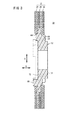
例えば、図5に示すように、先ず、薄板状金属プレート90が成形されるとともに、荷重受け部76、80及び82に対応する樹脂部材92が予め成形される(図5中、(a)参照)。
For example, as shown in FIG. 5, first, a
次いで、金属プレート90に設けられた孔部90aに樹脂部材92のボス部92aを挿入させた後(図5中、(b)参照)、前記ボス部92aを熱かしめする。これにより、樹脂部材92と金属プレート90とは、一体化される(図5中、(c)参照)。
Next, after the
さらに、図5(d)に示すように、金属プレート90の外周縁部に絶縁被覆処理を施すことにより、第1シール部材52、第2シール部材54及び第3シール部材56が成形される。これにより、第1セパレータ24、第2セパレータ26及び第3セパレータ28が製作される。
Further, as shown in FIG. 5 (d), the
ここで、図6に示すように、荷重受け部76、80及び82は、金属プレート90に設けられている切り欠き部90bに対応して一体化されている。従って、荷重受け部76、80及び82に形成される孔部78a、78b、84a、84b及び86a、86bは、この荷重受け部76、80及び82のみを積層方向に貫通しており、前記孔部78a、78b、84a、84b及び86a、86bに金属部分が露呈することはない。
Here, as shown in FIG. 6, the
また、上記の熱かしめによる製造方法の他、射出成形による製造方法が採用される。図7に示すように、金属プレート90が用意され(図7中、(a)参照)、この金属プレート90が図示しない射出成形機に装填された状態で、溶融樹脂を用いて荷重受け部76、80及び82が射出成形される(図7中、(b)参照)。さらに、図7(c)に示すように、金属プレート90の所望の部位を覆って絶縁被覆処理を施すことにより、第1シール部材52、第2シール部材54及び第3シール部材56が成形される。
In addition to the above-described manufacturing method by heat caulking, a manufacturing method by injection molding is employed. As shown in FIG. 7, a
次に、燃料電池スタック10を組み付ける作業について、以下に説明する。
Next, the operation of assembling the
先ず、燃料電池ユニット12では、第1セパレータ24と第2セパレータ26との間に、第1電解質膜・電極構造体22aが配設されるとともに、前記第2セパレータ26と第3セパレータ28との間に、第2電解質膜・電極構造体22bが配設される(図2参照)。この状態で、第1セパレータ24、第2セパレータ26及び第3セパレータ28同士が積層方向(矢印A方向)に押圧される。
First, in the
このため、図3に示すように、第2セパレータ26に一体成形されている位置決め部材62では、第1凸状部68が第1セパレータ24の第1孔部64に嵌合する。一方、位置決め部材62の第2凸状部70は、第3セパレータ28の第2孔部66に嵌合する。従って、第1セパレータ24〜第3セパレータ28同士は、位置決め機構60を介して位置決めされるとともに、燃料電池ユニット12が組み付けられる。
For this reason, as shown in FIG. 3, in the positioning
また、所定数の燃料電池ユニット12では、それぞれ荷重受け部76、80及び82の一方の孔部78a、84a及び86aに樹脂クリップ88が挿入され、この樹脂クリップ88を介して第1セパレータ24、第2セパレータ26及び第3セパレータ28同士が互いに保持される。
Further, in the predetermined number of
他の所定数の燃料電池ユニット12では、それぞれ荷重受け部76、80及び82の他方の孔部78b、84b及び86bに樹脂クリップ88が挿入され、第1セパレータ24、第2セパレータ26及び第3セパレータ28が一体に保持される。
In another predetermined number of
このように組み付けられた各燃料電池ユニット12は、孔部78a、84a及び86aに挿入された樹脂クリップ88と、孔部78b、84b及び86bに挿入された樹脂クリップ88とが交互になるように、図示しないガイドレールに沿って互いに積層される。
Each
その際、各燃料電池ユニット12では、略中央に配置されている第2セパレータ26の側部に一体化された荷重受け部80が、第1セパレータ24の荷重受け部76及び第3セパレータ28の荷重受け部82よりも外方に膨出形成されている。
At that time, in each
従って、荷重受け部80のみが樹脂性ガイド部として機能し、この荷重受け部80をガイドレールに沿って案内させるだけでよく、摺動抵抗が低減されるとともに、燃料電池ユニット12同士を容易且つ正確に積層することが可能になるという効果が得られる。
Therefore, only the
このように構成される燃料電池スタック10の動作について、以下に説明する。
The operation of the
先ず、図1に示すように、燃料電池スタック10では、酸化剤ガス入口連通孔30aに酸素含有ガス等の酸化剤ガス(空気)が供給されるとともに、燃料ガス入口連通孔32aに水素含有ガス等の燃料ガスが供給される。さらに、2つの冷却媒体入口連通孔34aには、純水やエチレングリコール、オイル等の冷却媒体が供給される。
First, as shown in FIG. 1, in the
図2に示すように、酸化剤ガスは、燃料電池ユニット12の酸化剤ガス入口連通孔30aに供給されて矢印A方向に移動し、第2セパレータ26の第1酸化剤ガス流路46及び第3セパレータ28の第2酸化剤ガス流路50に導入される。第1酸化剤ガス流路46に導入された酸化剤ガスは、第1電解質膜・電極構造体22aのカソード側電極40に沿って移動する一方、第2酸化剤ガス流路50に導入された酸化剤ガスは、第2電解質膜・電極構造体22bのカソード側電極40に沿って移動する。
As shown in FIG. 2, the oxidant gas is supplied to the oxidant gas
燃料ガスは、燃料電池ユニット12の燃料ガス入口連通孔32aから第1セパレータ24の第1燃料ガス流路42及び第2セパレータ26の第2燃料ガス流路48に導入される。このため、燃料ガスは、第1電解質膜・電極構造体22a及び第2電解質膜・電極構造体22bの各アノード側電極38に沿って移動する。
The fuel gas is introduced into the first
従って、第1電解質膜・電極構造体22a及び第2電解質膜・電極構造体22bでは、各カソード側電極40に供給される酸化剤ガスと、各アノード側電極38に供給される燃料ガスとが、図示しない電極触媒層内で電気化学反応により消費され、発電が行われる。
Therefore, in the first electrolyte membrane /
次いで、各カソード側電極40に供給されて消費された酸化剤ガスは、酸化剤ガス出口連通孔30bに沿って流動した後、燃料電池スタック10から排出される。同様に、各アノード側電極38に供給されて消費された燃料ガスは、燃料ガス出口連通孔32bに排出されて流動し、燃料電池スタック10から排出される。
Next, the oxidant gas supplied to and consumed by each
また、冷却媒体は、冷却媒体入口連通孔34aから燃料電池ユニット12間の冷却媒体流路44に導入された後、矢印B方向に沿って流動する。この冷却媒体は、第1電解質膜・電極構造体22a及び第2電解質膜・電極構造体22bを間引き冷却した後、冷却媒体出口連通孔34bを移動して燃料電池スタック10から排出される。
The cooling medium flows in the direction of arrow B after being introduced into the cooling
ところで、燃料電池スタック10は、車載用として図示しない車両に搭載されており、その積層方向(矢印A方向)が車長方向に向かって配置されている。そして、燃料電池スタック10に対し、衝突等によって側方から外部荷重Fが付与されると(図4参照)、ケーシング14を構成する側部プレート18a(又は18c)が燃料電池ユニット12側に変形する。
By the way, the
その際、各燃料電池ユニット12では、第2セパレータ26の外周部に、外方に突出して荷重受け部80が設けられており、側部プレート18aに付与された外部荷重Fが、この側部プレート18aに接触する荷重受け部80により受けられる。このため、荷重受け部80は、外部荷重Fによって内方に変形乃至移動しようとする。
At that time, in each
この場合、各燃料電池ユニット12では、荷重受け部76、80、82の孔部78a、84a及び86a(又は78b、84b及び86b)に樹脂クリップ88が挿入されており、この樹脂クリップ88を介して第1セパレータ24、第2セパレータ26及び第3セパレータ28が一体に保持されている。従って、荷重受け部80に付与された外部荷重Fは、樹脂クリップ88を介して荷重受け部76、82にも分散され、第2セパレータ26に外部荷重Fが集中して作用することがない。
In this case, in each
これにより、燃料電池ユニット12内には、ずれによるシール性の低下を惹起することがなく、しかも、側部プレート18aに荷重受け部80が接触することによって、第2セパレータ26の短絡を良好に阻止することができるという効果が得られる。
As a result, the
特に、荷重受け部80は、金属プレート90の孔部90aに対応して設けられるとともに、各荷重受け部76、80及び82を一体化する接続部材として、樹脂クリップ88が設けられている。このため、車両衝突時等に外部荷重Fが付与される際、側部プレート18aが内方に変形しても、この側部プレート18aと第2セパレータ26の金属部分とが接触することを可及的に阻止し、前記第2セパレータ26の短絡が確実に阻止されるという利点がある。
In particular, the
図8は、本発明の第2の実施形態に係る燃料電池スタック100の要部拡大断面図である。なお、第1の実施形態に係る燃料電池スタック10と同一の構成要素には同一の参照符号を付して、その詳細な説明は省略する。また、以下に説明する第3及び第4の実施形態においても同様に、その詳細な説明は省略する。
FIG. 8 is an enlarged cross-sectional view of a main part of a
燃料電池スタック100は、各燃料電池ユニット12を構成する荷重受け部76、80及び82を一体に保持する接続部材、例えば、絶縁性樹脂クリップ102を備える。この樹脂クリップ102は、首部88a側からフランジ部88bの途上まで延在するスリット104を設ける。
The
このように構成される第2の実施形態では、樹脂クリップ102がスリット104を設けることにより、前記樹脂クリップ102自体が弾性体構造を有している。このため、ケーシング14に外部荷重Fが付与され、荷重受け部80を介して樹脂クリップ102に前記外部荷重Fが付与されると、前記樹脂クリップ102は、スリット104を介して弾性変形し、前記外部荷重Fを吸収することが可能になる。
In the second embodiment configured as described above, the
従って、樹脂クリップ102は、荷重吸収機能と第1セパレータ24、第2セパレータ26及び第3セパレータ28への荷重分配機能とを有することができ、燃料電池ユニット12自体のずれやシール不良を一層確実に阻止することが可能になるという効果が得られる。
Therefore, the
図9は、本発明に関連する燃料電池スタック110の要部拡大断面図である。
Figure 9 is an enlarged cross-sectional view of a
各燃料電池ユニット12を構成する第1セパレータ24、第2セパレータ26及び第3セパレータ28には、荷重受け部112、114及び116が一体化されるとともに、前記荷重受け部114が、前記荷重受け部112、116よりも外方に突出している。図9及び図10に示すように、荷重受け部112、114及び116の先端側には、複数の小孔(孔部)118が形成される。
The
荷重受け部112、114及び116には、樹脂クリップ102(又は88)が挿入されており、第1セパレータ24、第2セパレータ26及び第3セパレータ28が一体に保持される。
A resin clip 102 (or 88) is inserted into the
このように構成される燃料電池スタック110では、図9に示すように、ケーシング14に外部荷重Fが付与され、側部プレート18aが内方に変形して荷重受け部114の先端に当接すると、この荷重受け部114は、複数の小孔118を介して優先的に破損される。
In the
このため、外部荷重Fは、荷重受け部114の破損によって良好に吸収され、第1セパレータ24、第2セパレータ26及び第3セパレータ28のずれを可及的に阻止することができる。これにより、シール不良や短絡の発生を確実に阻止することができる等、第1及び第2の実施形態と同様の効果が得られる。なお、複数の小孔118は、少なくとも第2セパレータ26に一体化される荷重受け部114に設けていればよい。
For this reason, the external load F is favorably absorbed by the breakage of the
図11は、本発明の第3の実施形態に係る燃料電池スタック120の要部拡大断面図であり、図12は、前記燃料電池スタック120を構成する燃料電池ユニット122の分解斜視説明図である。
FIG. 11 is an enlarged cross-sectional view of a main part of a
第1セパレータ24には、第1孔部64を設ける荷重受け部124が上下両端略中央に一体に設けられるとともに、第3セパレータ28には、第2孔部66を設ける荷重受け部126が上下両端略中央に一体に設けられている。第2セパレータ26は、位置決め部材62を一体に設ける荷重受け部128が上下両端略中央に設けられる。荷重受け部128は、荷重受け部124、126よりも外方に突出している。
The
このように構成される第3の実施形態では、位置決め機構60を構成する位置決め部材62が荷重受け部128に一体に設けられるとともに、第1孔部64及び第2孔部66が荷重受け部124、126に一体に設けられている。従って、位置決め機構60の構成が簡素化され、各燃料電池ユニット122の製造コストが有効に削減されるという効果が得られる。
In the third embodiment configured as described above, the positioning
なお、第1〜第3の実施形態では、第1電解質膜・電極構造体22a及び第2電解質膜・電極構造体22bと、第1セパレータ24〜第3セパレータ28とを備えた燃料電池ユニット12、122を用いて説明したが、これに限定されるものではない。実質的には、1つ以上の電解質膜・電極構造体と2つ以上のセパレータを備えていればよく、以下に例示する。
In the first to third embodiments, the
図13は、本発明の第4の実施形態に係る燃料電池スタックを構成する燃料電池(単位セル)130の分解斜視説明図である。 FIG. 13 is an exploded perspective view of a fuel cell (unit cell) 130 constituting a fuel cell stack according to the fourth embodiment of the present invention.
燃料電池130は、電解質膜・電極構造体132を挟持する第1セパレータ134及び第2セパレータ136を備える。燃料電池スタックは、上記の燃料電池130を矢印A方向に積層して構成される。
The
この第4の実施形態では、燃料電池130が、単一の電解質膜・電極構造体132を第1セパレータ134と第2セパレータ136とにより挟持している。この構成を上記の第1〜第3の実施形態に適用することができ、これによって、第4の実施形態では、上記の第1〜第3の実施形態と同様の効果が得られる。
In the fourth embodiment, the
10、100、110、120…燃料電池スタック
12、122…燃料電池ユニット 16a、16b…エンドプレート
18a〜18d…側部プレート 22a、22b…電解質膜・電極構造体
24、26、28、134、136…セパレータ
36…固体高分子電解質膜 38…アノード側電極
40…カソード側電極 42、48…燃料ガス流路
44…冷却媒体流路 46、50…酸化剤ガス流路
60…位置決め機構 62…位置決め部材
64、66、78a、78b、84a、84b、86a、86b…孔部
76、80、82、112、114、116、124、126、128…荷重受け部
88、102…樹脂クリップ 104…スリット
118…小孔 130…燃料電池
DESCRIPTION OF
Claims (3)
複数の前記セパレータを、積層方向に一体に保持する接続部材と、
前記接続部材により一体に保持される前記セパレータの中、少なくとも1つのセパレータの外周部に設けられ、他のセパレータの外周部より外方に突出して前記ケーシングの内面に接触し、外部からの荷重を受けるための樹脂製ガイド部と、
を備え、
前記樹脂製ガイド部には、前記接続部材である絶縁性クリップを挿入するための孔部が前記積層方向に形成されることを特徴とする燃料電池スタック。 A fuel cell stack comprising an electrolyte / electrode structure provided with a pair of electrodes on both sides of an electrolyte and a separator, and a fuel cell stack accommodated in a casing,
A connection member that integrally holds the plurality of separators in the stacking direction;
Among the separators that are integrally held by the connecting member, the separator is provided on the outer peripheral portion of at least one separator, protrudes outward from the outer peripheral portion of the other separator, contacts the inner surface of the casing, and receives an external load. A resin guide for receiving,
Equipped with a,
Wherein the resin guide portion, the fuel cell stack hole for inserting an insulating clip is the connecting member is characterized Rukoto formed in the stacking direction.
複数の前記金属セパレータを、積層方向に一体に保持する接続部材と、
前記接続部材により一体に保持される前記金属セパレータの中、少なくとも1つの金属セパレータの外周部に、前記シール部材とは別部材で設けられ、他の金属セパレータの外周部より外方に突出して前記ケーシングの内面に接触し、外部からの荷重を受けるための樹脂製ガイド部と、
を備えることを特徴とする燃料電池スタック。 A fuel cell stack including an electrolyte / electrode structure provided with a pair of electrodes on both sides of an electrolyte and a metal separator integrally formed with a seal member, and a fuel cell stack accommodated in a casing ,
A connecting member that integrally holds the plurality of metal separators in the stacking direction;
Among the metal separators that are integrally held by the connecting member, the outer periphery of at least one metal separator is provided as a separate member from the seal member, and protrudes outward from the outer periphery of the other metal separator. A resin guide for contacting the inner surface of the casing and receiving a load from the outside ;
Fuel cell stack according to claim Rukoto equipped with.
Priority Applications (4)
| Application Number | Priority Date | Filing Date | Title |
|---|---|---|---|
| JP2006199566A JP5128789B2 (en) | 2006-07-21 | 2006-07-21 | Fuel cell stack |
| CN2007101368383A CN101110485B (en) | 2006-07-21 | 2007-07-17 | Fuel cell stack |
| CA2593944A CA2593944C (en) | 2006-07-21 | 2007-07-18 | Fuel cell stack |
| US11/880,244 US8007950B2 (en) | 2006-07-21 | 2007-07-20 | Fuel cell stack |
Applications Claiming Priority (1)
| Application Number | Priority Date | Filing Date | Title |
|---|---|---|---|
| JP2006199566A JP5128789B2 (en) | 2006-07-21 | 2006-07-21 | Fuel cell stack |
Related Child Applications (1)
| Application Number | Title | Priority Date | Filing Date |
|---|---|---|---|
| JP2012179140A Division JP5437454B2 (en) | 2012-08-13 | 2012-08-13 | Fuel cell stack |
Publications (3)
| Publication Number | Publication Date |
|---|---|
| JP2008027761A JP2008027761A (en) | 2008-02-07 |
| JP2008027761A5 JP2008027761A5 (en) | 2009-09-03 |
| JP5128789B2 true JP5128789B2 (en) | 2013-01-23 |
Family
ID=38973725
Family Applications (1)
| Application Number | Title | Priority Date | Filing Date |
|---|---|---|---|
| JP2006199566A Active JP5128789B2 (en) | 2006-07-21 | 2006-07-21 | Fuel cell stack |
Country Status (4)
| Country | Link |
|---|---|
| US (1) | US8007950B2 (en) |
| JP (1) | JP5128789B2 (en) |
| CN (1) | CN101110485B (en) |
| CA (1) | CA2593944C (en) |
Families Citing this family (20)
| Publication number | Priority date | Publication date | Assignee | Title |
|---|---|---|---|---|
| JP4515233B2 (en) * | 2004-11-24 | 2010-07-28 | 本田技研工業株式会社 | Fuel cell and cell fastening pin |
| JP5231083B2 (en) * | 2007-06-11 | 2013-07-10 | 本田技研工業株式会社 | Fuel cell stack |
| JP5191868B2 (en) * | 2008-11-20 | 2013-05-08 | 本田技研工業株式会社 | Fuel cell |
| JP4871348B2 (en) | 2008-12-09 | 2012-02-08 | 本田技研工業株式会社 | Fuel cell stack |
| US8728683B2 (en) | 2009-05-20 | 2014-05-20 | Honda Motor Co., Ltd. | Fuel cell |
| JP5043064B2 (en) * | 2009-05-20 | 2012-10-10 | 本田技研工業株式会社 | Fuel cell |
| US8968957B2 (en) | 2010-03-01 | 2015-03-03 | Honda Motor Co., Ltd. | Fuel cell |
| CA2801416C (en) * | 2010-06-01 | 2015-03-10 | Nissan Motor Co., Ltd. | Fuel cell |
| JP5666396B2 (en) * | 2011-07-14 | 2015-02-12 | 本田技研工業株式会社 | Manufacturing method of metal separator for fuel cell |
| JP5809614B2 (en) * | 2012-09-27 | 2015-11-11 | 本田技研工業株式会社 | Fuel cell stack |
| JP2014096358A (en) | 2012-10-11 | 2014-05-22 | Honda Motor Co Ltd | Fuel cell stack |
| JP6021683B2 (en) * | 2013-02-21 | 2016-11-09 | 本田技研工業株式会社 | Fuel cell and assembly method thereof |
| JP6116933B2 (en) * | 2013-02-21 | 2017-04-19 | 本田技研工業株式会社 | Fuel cell |
| GB201312803D0 (en) * | 2013-07-17 | 2013-08-28 | Itm Power Research Ltd | Cell component |
| US9831482B2 (en) | 2013-09-06 | 2017-11-28 | Johnson Controls Technology Company | Battery module lid system and method |
| JP6153891B2 (en) * | 2014-05-29 | 2017-06-28 | 本田技研工業株式会社 | Fuel cell stack |
| JP6442304B2 (en) | 2015-02-02 | 2018-12-19 | 本田技研工業株式会社 | Fuel cell stack |
| JP6576977B2 (en) * | 2017-06-15 | 2019-09-18 | 本田技研工業株式会社 | Fuel cell separator member and fuel cell stack |
| JP7088769B2 (en) * | 2018-07-26 | 2022-06-21 | 本田技研工業株式会社 | Fuel cell stack |
| KR20220033785A (en) * | 2020-09-10 | 2022-03-17 | 현대자동차주식회사 | Fuel cell |
Family Cites Families (7)
| Publication number | Priority date | Publication date | Assignee | Title |
|---|---|---|---|---|
| JP4422458B2 (en) * | 2002-11-07 | 2010-02-24 | 本田技研工業株式会社 | Fuel cell |
| JP3957294B2 (en) | 2003-02-04 | 2007-08-15 | 本田技研工業株式会社 | Fuel cell |
| JP4645092B2 (en) * | 2004-07-27 | 2011-03-09 | 日産自動車株式会社 | Fuel cell device |
| JP4789448B2 (en) * | 2004-10-08 | 2011-10-12 | 本田技研工業株式会社 | Fuel cell stack |
| JP4417224B2 (en) * | 2004-10-25 | 2010-02-17 | 本田技研工業株式会社 | Fuel cell stack |
| JP4882221B2 (en) * | 2004-11-17 | 2012-02-22 | 日産自動車株式会社 | Separator bonding method |
| JP4515233B2 (en) * | 2004-11-24 | 2010-07-28 | 本田技研工業株式会社 | Fuel cell and cell fastening pin |
-
2006
- 2006-07-21 JP JP2006199566A patent/JP5128789B2/en active Active
-
2007
- 2007-07-17 CN CN2007101368383A patent/CN101110485B/en active Active
- 2007-07-18 CA CA2593944A patent/CA2593944C/en not_active Expired - Fee Related
- 2007-07-20 US US11/880,244 patent/US8007950B2/en active Active
Also Published As
| Publication number | Publication date |
|---|---|
| JP2008027761A (en) | 2008-02-07 |
| CN101110485A (en) | 2008-01-23 |
| US20080268319A1 (en) | 2008-10-30 |
| CA2593944C (en) | 2010-06-01 |
| US8007950B2 (en) | 2011-08-30 |
| CA2593944A1 (en) | 2008-01-21 |
| CN101110485B (en) | 2010-10-06 |
Similar Documents
| Publication | Publication Date | Title |
|---|---|---|
| JP5128789B2 (en) | Fuel cell stack | |
| JP6368807B2 (en) | Manufacturing method of fuel cell stack and manufacturing method of metal separator for fuel cell | |
| US8703356B2 (en) | Separator of fuel battery, method of joining separator, and fuel battery | |
| JP4417224B2 (en) | Fuel cell stack | |
| JP4422458B2 (en) | Fuel cell | |
| JP2006236611A (en) | Fuel cell stack | |
| JP5236874B2 (en) | Fuel cell stack | |
| JP4820068B2 (en) | Fuel cell stack | |
| JP5254771B2 (en) | Fuel cell | |
| JP4928141B2 (en) | Method for manufacturing fuel cell separator and method for assembling fuel cell | |
| JP4165876B2 (en) | Fuel cell stack | |
| JP4989161B2 (en) | Fuel cell stack | |
| JP4262563B2 (en) | Fuel cell stack | |
| JP4789478B2 (en) | Fuel cell stack and assembly method thereof | |
| JP4664030B2 (en) | Fuel cell stack | |
| JP4865238B2 (en) | Fuel cell stack | |
| JP5437454B2 (en) | Fuel cell stack | |
| JP4417204B2 (en) | Fuel cell stack | |
| JP5207834B2 (en) | Automotive fuel cell stack | |
| JP5318461B2 (en) | Fuel cell stack | |
| JP4921827B2 (en) | Fuel cell stack and method for producing carbon separator | |
| JP4452585B2 (en) | Fuel cell stack | |
| JP5021698B2 (en) | Fuel cell stack | |
| JP5295639B2 (en) | Fuel cell stack | |
| JP2007220331A (en) | Fuel cell stack |
Legal Events
| Date | Code | Title | Description |
|---|---|---|---|
| A521 | Request for written amendment filed |
Free format text: JAPANESE INTERMEDIATE CODE: A523 Effective date: 20090717 |
|
| A621 | Written request for application examination |
Free format text: JAPANESE INTERMEDIATE CODE: A621 Effective date: 20090717 |
|
| A977 | Report on retrieval |
Free format text: JAPANESE INTERMEDIATE CODE: A971007 Effective date: 20120531 |
|
| A131 | Notification of reasons for refusal |
Free format text: JAPANESE INTERMEDIATE CODE: A131 Effective date: 20120612 |
|
| A521 | Request for written amendment filed |
Free format text: JAPANESE INTERMEDIATE CODE: A523 Effective date: 20120813 |
|
| TRDD | Decision of grant or rejection written | ||
| A01 | Written decision to grant a patent or to grant a registration (utility model) |
Free format text: JAPANESE INTERMEDIATE CODE: A01 Effective date: 20121030 |
|
| A01 | Written decision to grant a patent or to grant a registration (utility model) |
Free format text: JAPANESE INTERMEDIATE CODE: A01 |
|
| A61 | First payment of annual fees (during grant procedure) |
Free format text: JAPANESE INTERMEDIATE CODE: A61 Effective date: 20121101 |
|
| R150 | Certificate of patent or registration of utility model |
Free format text: JAPANESE INTERMEDIATE CODE: R150 Ref document number: 5128789 Country of ref document: JP Free format text: JAPANESE INTERMEDIATE CODE: R150 |
|
| FPAY | Renewal fee payment (event date is renewal date of database) |
Free format text: PAYMENT UNTIL: 20151109 Year of fee payment: 3 |
|
| R250 | Receipt of annual fees |
Free format text: JAPANESE INTERMEDIATE CODE: R250 |