JP5128522B2 - Heat exchanger, air conditioner - Google Patents
Heat exchanger, air conditioner Download PDFInfo
- Publication number
- JP5128522B2 JP5128522B2 JP2009051904A JP2009051904A JP5128522B2 JP 5128522 B2 JP5128522 B2 JP 5128522B2 JP 2009051904 A JP2009051904 A JP 2009051904A JP 2009051904 A JP2009051904 A JP 2009051904A JP 5128522 B2 JP5128522 B2 JP 5128522B2
- Authority
- JP
- Japan
- Prior art keywords
- heat exchanger
- heat transfer
- peripheral surface
- tube
- outer peripheral
- Prior art date
- Legal status (The legal status is an assumption and is not a legal conclusion. Google has not performed a legal analysis and makes no representation as to the accuracy of the status listed.)
- Expired - Fee Related
Links
Images


Landscapes
- Details Of Heat-Exchange And Heat-Transfer (AREA)
- Heat-Exchange Devices With Radiators And Conduit Assemblies (AREA)
Description
本発明は熱交換器及びこれを用いた空気調和機に係り、特に形状を改良した熱交換器及びこれを用いた空気調和機に関する。 The present invention relates to a heat exchanger and an air conditioner using the heat exchanger, and more particularly to a heat exchanger having an improved shape and an air conditioner using the heat exchanger.
従来、熱交換効率を向上させる目的で、空気抵抗を低減させる楕円管あるいは扁平管を用いる非円形管熱交換器が多く提案されている。 Conventionally, for the purpose of improving heat exchange efficiency, many non-circular tube heat exchangers using an elliptic tube or a flat tube that reduce air resistance have been proposed.
そして、従来の非円形管熱交換器には、複数の伝熱管をヘッダーに溶着する構造のものが用いられている(例えば、特許文献1、特許文献2参照)。 And the thing of the structure which welds a some heat exchanger tube to a header is used for the conventional non-circular tube heat exchanger (for example, refer patent document 1, patent document 2).
しかし、特許文献1及び特許文献2に記載の熱交換器では、ヘッダー構造が複雑になり、ヘッダーと伝熱管の溶着に、大掛かりなロー付け設備を必要とする。また、このようなヘッダー方式は、分流が難しく、空気調和機用の木目細かい分流には対応できない問題がある。
However, in the heat exchangers described in Patent Document 1 and
本発明は、上述した事情を考慮してなされたものであり、楕円形状または扁平円形状の伝熱管を用いるとともに、リターンベンドは内周面を伝熱管の外周面の形状と同一形状に形成し、外周面を円形に形成することで、空気側圧力損失が小さくかつ、管内熱伝達率が高く、加工性、製造性がよい熱交換器を提供することを目的とする。 The present invention has been made in consideration of the above-described circumstances, and uses an elliptical or flat circular heat transfer tube, and the return bend has an inner peripheral surface formed in the same shape as the outer peripheral surface of the heat transfer tube. An object of the present invention is to provide a heat exchanger that has a small air-side pressure loss, a high heat transfer coefficient in the tube, and good workability and manufacturability by forming the outer peripheral surface in a circular shape.
また、空気側圧力損失が小さくかつ、管内熱伝達率が高く、加工性、製造性がよい熱交換器を用いた空気調和機を提供することを目的とする。 It is another object of the present invention to provide an air conditioner using a heat exchanger that has a small air-side pressure loss, a high in-tube heat transfer rate, and good workability and manufacturability.
上述した目的を達成するため、本発明に係る熱交換器は、互いに所定間隔を存して並設され、互いの隙間に熱交換空気を流通させる複数枚のフィンと、このフィンを貫通しかつ、フィンの長手方向に沿って配列され、内部に熱交換媒体を導通させる流路を形成する伝熱管と、この伝熱管の端部同士を接続するU字状のリターンベンドとを具備した熱交換器において、前記伝熱管は、外周面が楕円形状または扁平円形状を有し、前記リターンベンドは、内周面が前記伝熱管の外周面の形状と同一形状に形成されかつ、外周面が円形に形成されていることを特徴とする。 In order to achieve the above-described object, a heat exchanger according to the present invention is arranged in parallel with a predetermined interval between each other, a plurality of fins that circulate heat exchange air in the gaps between each other, and through these fins. , Heat exchange comprising a heat transfer tube arranged along the longitudinal direction of the fins and forming a flow path through which the heat exchange medium is conducted, and a U-shaped return bend connecting ends of the heat transfer tubes The heat transfer tube has an elliptical or flat circular outer peripheral surface, and the return bend has an inner peripheral surface formed in the same shape as the outer peripheral surface of the heat transfer tube, and the outer peripheral surface is circular. It is characterized by being formed.
また、本発明の他の態様によれば、本発明に係る空気調和機は、圧縮機、四方切換弁、室外熱交換器、膨張装置、室内熱交換器を冷媒配管で連結した冷凍サイクルを備えた空気調和機において、前記室外熱交換器および前記室内熱交換器の少なくともいずれか一方は、互いに所定間隔を存して並設され、互いの隙間に熱交換空気を流通させる複数枚のフィンと、このフィンを貫通しかつ、フィンの長手方向に沿って配列され、内部に熱交換媒体を導通させる流路を形成する伝熱管と、この伝熱管の端部同士を接続するU字状のリターンベンドとを具備し、前記伝熱管の外周面が楕円形状または扁平円形状を有し、前記リターンベンドは内周面が前記伝熱管の外周面の形状と同一形状に形成されかつ、外周面が円形に形成されていることを特徴とする。 According to another aspect of the present invention, an air conditioner according to the present invention includes a refrigeration cycle in which a compressor, a four-way switching valve, an outdoor heat exchanger, an expansion device, and an indoor heat exchanger are connected by a refrigerant pipe. In the above air conditioner, at least one of the outdoor heat exchanger and the indoor heat exchanger is arranged in parallel with a predetermined interval between each other, and a plurality of fins that circulate the heat exchange air in the gap between each other; A heat transfer pipe which penetrates the fin and is arranged along the longitudinal direction of the fin and forms a flow path through which the heat exchange medium is conducted, and a U-shaped return which connects the ends of the heat transfer pipe A bend, the outer peripheral surface of the heat transfer tube has an elliptical shape or a flat circular shape, the return bend has an inner peripheral surface formed in the same shape as the outer peripheral surface of the heat transfer tube, and the outer peripheral surface is It is formed in a circular shape To.
本発明に係る熱交換器によれば、楕円形状または扁平円形状の伝熱管を用いるとともに、リターンベンドは内周面を伝熱管の外周面の形状と同一形状に形成し、外周面を円形に形成することで、空気側圧力損失が小さくかつ、管内熱伝達率が高く、加工性製造性がよい熱交換器を提供することができる。 According to the heat exchanger of the present invention, an elliptical or flat circular heat transfer tube is used, and the return bend has an inner peripheral surface formed in the same shape as the outer peripheral surface of the heat transfer tube, and the outer peripheral surface is circular. By forming the heat exchanger, it is possible to provide a heat exchanger having a small air-side pressure loss, a high in-tube heat transfer coefficient, and good workability manufacturability.
また、本発明に係る空気調和機によれば、空気側圧力損失が小さくかつ、管内熱伝達率が高く、加工性製造性がよい熱交換器を用いた空気調和機を提供することができる。 Moreover, according to the air conditioner which concerns on this invention, the air conditioner using the heat exchanger with a small air side pressure loss, a high heat transfer coefficient in a pipe | tube, and favorable workability manufacturability can be provided.
本発明の一実施形態に係る熱交換器及びこれを用いた空気調和機に用いる冷凍サイクル装置について、図面を参照して説明する。 A heat exchanger according to an embodiment of the present invention and a refrigeration cycle apparatus used in an air conditioner using the heat exchanger will be described with reference to the drawings.
図1に示すように、本発明に係る空気調和機は室外機22Aと室内機22Bを備え、室外機22Aには冷凍サイクル装置21の一部を構成し、冷媒を圧縮する圧縮機23と、冷房運転あるいは暖房運転に応じて冷媒の流れを切り換える四方弁24、冷房運転時凝縮器として機能し、暖房運転時蒸発器として機能する本発明に係る熱交換器としての室外熱交換器1と、冷媒を減圧する膨張装置25とが収容され、室内機22Bには冷凍サイクル装置21の一部を構成し、冷房運転時蒸発器として機能し、暖房運転時凝縮器として機能する室内熱交換器26が収容される。
As shown in FIG. 1, the air conditioner according to the present invention includes an
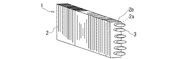
図2に示すように、本発明に係る熱交換器である室外熱交換器1は、フィンチューブ型であり、互いに所定間隔を存して並設され、互いの隙間に熱交換空気を流通させる複数枚のアルミニウム製板状のフィン2を、非円形の伝熱管3がフィン2に穿設され、周囲にカラー部2bが突設された多数の貫通孔2aを伝熱的に貫通している。
As shown in FIG. 2, the outdoor heat exchanger 1 that is a heat exchanger according to the present invention is a fin tube type, and is arranged in parallel with each other at a predetermined interval, and heat exchange air is circulated in the gaps between the two. A plurality of aluminum plate-
伝熱管3はフィン2の長手方向に沿って複数配列され、内部に熱交換媒体が流れる流路が設けられる。
A plurality of the heat transfer tubes 3 are arranged along the longitudinal direction of the
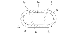
図3に示すように、伝熱管3の断面は非円形例えば楕円形状をなし、管外周面3a及び管内周面3bは楕円状をなしている。さらに、伝熱管3内に多数の流路3c、3c、3cを設けるために、伝熱管3内には、内部を略3分割するように平行な2個の仕切壁3d、3dが設けられている。
As shown in FIG. 3, the cross section of the heat transfer tube 3 is non-circular, for example, an elliptical shape, and the outer
なお、図4に示すように、伝熱管は断面を非円形例えば扁平円形状に形成し、内部を平行な2個の仕切壁3d、3dによって仕切るようにした伝熱管3Aであってもよい。
As shown in FIG. 4, the heat transfer tube may be a
図5に示すように、フィン2を伝熱的に貫通する伝熱管3、3Aの両端部には、この伝熱管3、3Aの端部3e同士を接続するリターンベンド4が溶着される。
As shown in FIG. 5, return bends 4 that connect the
リターンベンド4は、図6に示すように、U字状をなし、図7及び図8に示すように、ベンド外周面4aは円形をなし、ベント内周面4bは伝熱管3、3Aの管外周面3aの形状と同一の楕円形状又は扁平円形状に形成される。
The return bend 4 is U-shaped as shown in FIG. 6, the bend outer
リターンベンド4は、アルミ合金の押出し製法により製造されるが、ベント外周面4aが円形をなすことと内周面の短軸方向の肉厚が大きいことにより、曲げ加工時の管潰れを防止でき、U字状に加工し易い。
The return bend 4 is manufactured by an aluminum alloy extrusion manufacturing method, but the bent outer
また、伝熱管3、3Aはアルミ合金の押出し管製法により製造されるが、この伝熱管3、3Aは強度確保のため、内側に直線あるいは曲線形状の仕切壁3d(図3、図4)を設ける。
The
フィン2は長手方向が垂直方向に設置され、伝熱管3、3Aは長軸方向を水平方向にして設置されている。機械拡管あるいは液圧拡管により、フィン2と管外周面3aが伝熱的に密着結合される。
The
図5に示すように、熱交換器1の組立時、リターンベンド4により、伝熱管3、3Aの端部3eをリターンベンド4に挿入して接合(ロー付)することができ、伝熱管3、3Aの内部構造がどんな形状でもリターンベンド4と接合できる。また、伝熱管3、3Aの接続に、ヘッダーを用いることなく、リターンベンド4を用いるので、ヘッダー方式の分流の不具合を生じることもない。
As shown in FIG. 5, when assembling the heat exchanger 1, the
さらに、図3あるいは図4に示すように、伝熱管3、3Aの内部を多流路化することも容易にでき、また、伝熱管3、3Aの耐圧強度が向上し、高圧冷媒下での室外熱交換器1の使用も可能になる。
Furthermore, as shown in FIG. 3 or FIG. 4, the inside of the
また、本発明に係る熱交換器としての室外熱交換器1に用いる伝熱管の変形例について説明する。 Moreover, the modification of the heat exchanger tube used for the outdoor heat exchanger 1 as a heat exchanger which concerns on this invention is demonstrated.
上記実施形態における伝熱管が連続する仕切壁によって仕切られるのに対して、本変形例は仕切壁が上下に2分割される。 In contrast to the heat transfer tubes in the above embodiment that are partitioned by a continuous partition wall, in this modification, the partition wall is vertically divided into two.
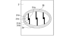
例えば、図9に示すように、伝熱管3Bの断面は非円形例えば楕円形状をなし、内部に4個の流路31c、31c、31c、31cが形成されるように、管内周面31bから突出する平行な3対の仕切壁31d、31d、31dが設けられている。
For example, as shown in FIG. 9, the cross section of the
仕切壁31dは管内周面31bの上部から下方に向かって突出するL字形状の上仕切壁31d1と、管内周面31bの下部から上方に向かって突出するL字形状の下仕切壁31d2からなり、上L字先端部31d3が下L字先端部31d4の下方に位置するとともに、上L字先端部31d3と下L字先端部31d4が間隔δを有して互いに対向するように設けられている。
伝熱管3Bは、アルミ合金材にて押出しにより製造され、仕切壁31dは伝熱管(管体)3Bと一体構造である。隙間δは短軸径の5〜15%程度に設定する。
The
図10及び図11は、本熱交換器1の製造時における伝熱管3Bのフィン2への貫通状態を示し、フィン2の貫通孔2aと伝熱管3Bの管外周面3a間には間隙gが設けられ、上L字先端部31d3、下L字先端部31d4間には、間隔δが設けられる。
10 and 11 show the state of penetration of the
図12は、本熱交換器1における伝熱管3Bのフィン2への伝熱的貫通(嵌着)状態を示し、伝熱管3Bの拡管後の状態である。
FIG. 12 shows a heat transfer penetration (fitting) state of the
拡管時、図10に示す状態から、伝熱管3B内を加圧すると、長軸に対して直角方向に外壁が伸びる。このように、圧力により、伝熱管3Bの外形を拡げ、フィン2との密着を容易にできる。
When expanding the tube, when the inside of the
伝熱管3Bの拡管(管体の伸び)につれ仕切壁31dが上下に移動し、上L字先端部31d3と下L字先端部31d4間の隙間δが減少する。さらに圧力を上げると、上L字先端部31d3と下L字先端部31d4が噛合う状態が発生する。
内圧が上記圧力より大きくなると、仕切壁31dが補強壁となり、変形しにくくなる。
When the internal pressure becomes larger than the above pressure, the
この状態を具体的に説明すると、図13に示すように、拡管域すなわち上L字先端部31d3と下L字先端部31d4が噛合う迄は、伝熱管3Bの短軸方向は変位する(伸びる)。
Specifically describing this state, as shown in FIG. 13, the tube expanding region ie above L-shaped
上L字先端部31d3と下L字先端部31d4の噛合い後は、設計圧力の3〜4倍の圧力がかかっても、伝熱管3Bの短軸方向は変位を抑えることができる。さらに、伝熱管3Bの耐圧向上により、高圧冷媒下での熱交換器1の使用も可能になる。
After the upper L-shaped
このように、熱交換器1の製造時における楕円形状の伝熱管3Bの管強度を大幅に向上させることができ、拡管が可能な熱交換器用楕円管を提供できる。
Thus, the tube strength of the elliptical
また、伝熱管3Bの強度が向上するとともに、楕円形状をなすことにより、空気調和機に用いた場合、熱交換器3Bを通過する空気抵抗が減少し、熱交換率が向上する。さらに、フィンカラー部に溜まるドレン水を排水し易く、また、室外機の熱交換器として用いた場合、フィンに付いた霜を除霜するのが容易である。
In addition, the strength of the
なお、本冷凍サイクル装置の室外熱交換器に、本発明に係る熱交換器を用いる例で説明したが、室内熱交換器のみに、あるいは室外熱交換器と室内熱交換器の両熱交換器に本発明に係る熱交換器を用いることもできる。 In addition, although demonstrated in the example which uses the heat exchanger which concerns on this invention for the outdoor heat exchanger of this refrigeration cycle apparatus, it is only an indoor heat exchanger, or both heat exchangers of an outdoor heat exchanger and an indoor heat exchanger The heat exchanger according to the present invention can also be used.
上記のように、本実施形態の熱交換器によれば、楕円形状または扁平円形状の伝熱管を用いるとともに、リターンベンドは内周面を伝熱管の外周面の形状と同一形状に形成し、外周面を円形に形成することで、空気側圧力損失が小さくかつ、管内熱伝達率が高く、加工性製造性がよい熱交換器が実現する。 As described above, according to the heat exchanger of the present embodiment, while using an elliptical or flat circular heat transfer tube, the return bend forms the inner peripheral surface in the same shape as the outer peripheral surface of the heat transfer tube, By forming the outer peripheral surface in a circular shape, a heat exchanger with low air-side pressure loss, high in-tube heat transfer coefficient, and good workability and manufacturability is realized.
また、本実施形態の熱交換器を用いた空気調和機によれば、空気側圧力損失が小さくかつ、管内熱伝達率が高く、加工性製造性がよい熱交換器を用いた空気調和機が実現する。 Moreover, according to the air conditioner using the heat exchanger of the present embodiment, the air conditioner using the heat exchanger having a small air-side pressure loss, a high heat transfer coefficient in the pipe, and good workability manufacturability. Realize.
1…室外熱交換器、2…フィン、2a…貫通孔、2b…カラー部、3…伝熱管、3a…管外周面、3b…管内周面、3c…流路、3d…仕切壁、3e…端部、4…リターンベンド、4a…ベンド外周面、4b…ベント内周面、21…冷凍サイクル装置、22A…室外機、22B…室内機、23…圧縮機、24…四方弁、25…膨張装置、26…室内熱交換器。 DESCRIPTION OF SYMBOLS 1 ... Outdoor heat exchanger, 2 ... Fin, 2a ... Through-hole, 2b ... Collar part, 3 ... Heat transfer pipe, 3a ... Pipe outer peripheral surface, 3b ... Pipe inner peripheral surface, 3c ... Channel, 3d ... Partition wall, 3e ... End part, 4 ... Return bend, 4a ... Bend outer peripheral surface, 4b ... Vent inner peripheral surface, 21 ... Refrigeration cycle device, 22A ... Outdoor unit, 22B ... Indoor unit, 23 ... Compressor, 24 ... Four-way valve, 25 ... Expansion Apparatus, 26 ... indoor heat exchanger.
Claims (3)
このフィンを貫通しかつ、フィンの長手方向に沿って配列され、内部に熱交換媒体を導通させる流路を形成する伝熱管と、
この伝熱管の端部同士を接続するU字状のリターンベンドとを具備した熱交換器において、
前記伝熱管は、外周面が楕円形状または扁平円形状を有し、
前記リターンベンドは、内周面が前記伝熱管の外周面の形状と同一形状に形成されかつ、外周面が円形に形成されたことを特徴とする熱交換器。 A plurality of fins that are arranged in parallel with each other at a predetermined interval and distribute heat exchange air in the gap between each other;
A heat transfer tube that penetrates the fins and is arranged along the longitudinal direction of the fins, and forms a flow path through which the heat exchange medium is conducted;
In the heat exchanger having a U-shaped return bend connecting the ends of the heat transfer tubes,
The heat transfer tube has an elliptical or flat circular outer peripheral surface;
The return bend is a heat exchanger characterized in that an inner peripheral surface is formed in the same shape as an outer peripheral surface of the heat transfer tube, and an outer peripheral surface is formed in a circular shape.
前記室外熱交換器および前記室内熱交換器の少なくともいずれか一方は、
互いに所定間隔を存して並設され、互いの隙間に熱交換空気を流通させる複数枚のフィンと、
このフィンを貫通しかつ、フィンの長手方向に沿って配列され、内部に熱交換媒体を導通させる流路を形成する伝熱管と、
この伝熱管の端部同士を接続するU字状のリターンベンドとを具備し、
前記伝熱管の外周面が楕円形状または扁平円形状を有し、
前記リターンベンドは内周面が前記伝熱管の外周面の形状と同一形状に形成されかつ、外周面が円形に形成されたことを特徴とする空気調和機。 In an air conditioner having a refrigeration cycle in which a compressor, a four-way switching valve, an outdoor heat exchanger, an expansion device, and an indoor heat exchanger are connected by a refrigerant pipe,
At least one of the outdoor heat exchanger and the indoor heat exchanger is
A plurality of fins that are arranged in parallel with each other at a predetermined interval and distribute heat exchange air in the gap between each other;
A heat transfer tube that penetrates the fins and is arranged along the longitudinal direction of the fins, and forms a flow path through which the heat exchange medium is conducted;
A U-shaped return bend connecting the ends of the heat transfer tubes,
The outer peripheral surface of the heat transfer tube has an elliptical shape or a flat circular shape,
The return bend has an inner peripheral surface formed in the same shape as the outer peripheral surface of the heat transfer tube, and the outer peripheral surface is formed in a circular shape.
Priority Applications (1)
| Application Number | Priority Date | Filing Date | Title |
|---|---|---|---|
| JP2009051904A JP5128522B2 (en) | 2009-03-05 | 2009-03-05 | Heat exchanger, air conditioner |
Applications Claiming Priority (1)
| Application Number | Priority Date | Filing Date | Title |
|---|---|---|---|
| JP2009051904A JP5128522B2 (en) | 2009-03-05 | 2009-03-05 | Heat exchanger, air conditioner |
Publications (2)
| Publication Number | Publication Date |
|---|---|
| JP2010203726A JP2010203726A (en) | 2010-09-16 |
| JP5128522B2 true JP5128522B2 (en) | 2013-01-23 |
Family
ID=42965379
Family Applications (1)
| Application Number | Title | Priority Date | Filing Date |
|---|---|---|---|
| JP2009051904A Expired - Fee Related JP5128522B2 (en) | 2009-03-05 | 2009-03-05 | Heat exchanger, air conditioner |
Country Status (1)
| Country | Link |
|---|---|
| JP (1) | JP5128522B2 (en) |
Families Citing this family (4)
| Publication number | Priority date | Publication date | Assignee | Title |
|---|---|---|---|---|
| JP2014119158A (en) * | 2012-12-14 | 2014-06-30 | Mitsubishi Electric Corp | Heat exchanger, and air conditioner incorporating the heat exchanger |
| CN107850358B (en) * | 2015-07-29 | 2020-06-12 | 三菱电机株式会社 | Heat exchanger and refrigeration cycle device |
| JP6821057B2 (en) * | 2017-12-11 | 2021-01-27 | 三菱電機株式会社 | Finless heat exchanger and refrigeration cycle equipment |
| JP7030172B1 (en) | 2020-11-16 | 2022-03-04 | 木村工機株式会社 | Heat pump type air conditioner |
Family Cites Families (4)
| Publication number | Priority date | Publication date | Assignee | Title |
|---|---|---|---|---|
| JPS6127131A (en) * | 1984-07-17 | 1986-02-06 | Matsushita Refrig Co | Manufacture of fin tube type heat exchanger |
| JPS61186986U (en) * | 1985-05-13 | 1986-11-21 | ||
| US5425414A (en) * | 1993-09-17 | 1995-06-20 | Evapco International, Inc. | Heat exchanger coil assembly |
| JP2004360184A (en) * | 2003-05-30 | 2004-12-24 | Katayama Kogyo Co Ltd | Bar-like member having excellent bending machining directivity |
-
2009
- 2009-03-05 JP JP2009051904A patent/JP5128522B2/en not_active Expired - Fee Related
Also Published As
| Publication number | Publication date |
|---|---|
| JP2010203726A (en) | 2010-09-16 |
Similar Documents
| Publication | Publication Date | Title |
|---|---|---|
| US9322602B2 (en) | Heat exchanger having a plurality of plate-like fins and a plurality of flat-shaped heat transfer pipes orthogonal to the plate-like fins | |
| US6928833B2 (en) | Finned tube for heat exchangers, heat exchanger, process for producing heat exchanger finned tube, and process for fabricating heat exchanger | |
| US20120103583A1 (en) | Heat exchanger and fin for the same | |
| WO2014147788A1 (en) | Heat exchanger, refrigeration cycle device, and production method for heat exchanger | |
| JP5128522B2 (en) | Heat exchanger, air conditioner | |
| JP5545160B2 (en) | Heat exchanger | |
| JP5911597B2 (en) | Flat shape heat transfer tube, method of manufacturing cross fin tube type heat exchanger equipped with the same, cross fin tube type heat exchanger manufactured by the method | |
| JP2006078163A (en) | Flat tube, plate body for manufacturing flat tube, and heat exchanger | |
| JP2012247091A (en) | Fin and tube type heat exchanger | |
| JP2008064427A (en) | Heat exchanger | |
| WO2013094084A1 (en) | Air conditioner | |
| JP2018124034A (en) | Tube for heat exchanger | |
| JP5063765B2 (en) | Heat exchanger, heat exchanger manufacturing method, refrigerator, and air conditioner | |
| JP5595343B2 (en) | Heat exchanger, refrigeration cycle circuit using the same, refrigerator using the refrigeration cycle circuit, and air conditioner | |
| WO2013118762A1 (en) | Fin tube-type heat exchanger | |
| JP2009250600A (en) | Copper flat heat-transfer pipe | |
| JP2011099620A (en) | Heat exchanger | |
| JP5525763B2 (en) | Heat transfer tube, heat exchanger, and air conditioner equipped with the heat exchanger | |
| KR101016696B1 (en) | turn fin type heat exchanger and manufacturing method for turn fin type heat exchanger | |
| JP2004239486A (en) | Heat exchanger and its manufacturing method | |
| JP2012202572A (en) | Fin-and-tube heat exchanger | |
| JP7100242B2 (en) | Heat exchanger | |
| JP2008281269A (en) | Flat tube and heat exchanger | |
| CN201628511U (en) | Heat exchanger and collecting pipe thereof | |
| AU2002339744B2 (en) | Finned tube for heat exchangers, heat exchanger, process for producing heat exchanger finned tube, and process for fabricating heat exchanger |
Legal Events
| Date | Code | Title | Description |
|---|---|---|---|
| A621 | Written request for application examination |
Free format text: JAPANESE INTERMEDIATE CODE: A621 Effective date: 20110921 |
|
| A977 | Report on retrieval |
Free format text: JAPANESE INTERMEDIATE CODE: A971007 Effective date: 20121012 |
|
| TRDD | Decision of grant or rejection written | ||
| A01 | Written decision to grant a patent or to grant a registration (utility model) |
Free format text: JAPANESE INTERMEDIATE CODE: A01 Effective date: 20121023 |
|
| A01 | Written decision to grant a patent or to grant a registration (utility model) |
Free format text: JAPANESE INTERMEDIATE CODE: A01 |
|
| A61 | First payment of annual fees (during grant procedure) |
Free format text: JAPANESE INTERMEDIATE CODE: A61 Effective date: 20121031 |
|
| R150 | Certificate of patent (=grant) or registration of utility model |
Free format text: JAPANESE INTERMEDIATE CODE: R150 |
|
| FPAY | Renewal fee payment (prs date is renewal date of database) |
Free format text: PAYMENT UNTIL: 20151109 Year of fee payment: 3 |
|
| LAPS | Cancellation because of no payment of annual fees |