JP2012202572A - Fin-and-tube heat exchanger - Google Patents
Fin-and-tube heat exchanger Download PDFInfo
- Publication number
- JP2012202572A JP2012202572A JP2011065290A JP2011065290A JP2012202572A JP 2012202572 A JP2012202572 A JP 2012202572A JP 2011065290 A JP2011065290 A JP 2011065290A JP 2011065290 A JP2011065290 A JP 2011065290A JP 2012202572 A JP2012202572 A JP 2012202572A
- Authority
- JP
- Japan
- Prior art keywords
- fin
- tube
- heat exchanger
- fins
- distance
- Prior art date
- Legal status (The legal status is an assumption and is not a legal conclusion. Google has not performed a legal analysis and makes no representation as to the accuracy of the status listed.)
- Withdrawn
Links
Images


Abstract
Description
本発明は、フィン・アンド・チューブ型熱交換器に係り、特に、家庭用エアコンや自動車用エアコン等の空調機において好適に用いられるフィン・アンド・チューブ型熱交換器に関するものである。 The present invention relates to a fin-and-tube heat exchanger, and more particularly to a fin-and-tube heat exchanger suitably used in an air conditioner such as a home air conditioner or an automobile air conditioner.
従来より、家庭用エアコンや自動車用エアコン、パッケージエアコン等の空調用機器の他、冷蔵庫、ヒートポンプ式給湯器等においては、蒸発器又は凝縮器として作動する熱交換器が用いられており、特に家庭用室内エアコンや業務用パッケージエアコンにおいては、伝熱管にフィンを組み付けてなる構造のフィン・アンド・チューブ型熱交換器が、最も一般的に用いられている。 Conventionally, heat exchangers that operate as evaporators or condensers have been used in refrigerators, heat pump water heaters, etc., in addition to air conditioning equipment such as home air conditioners, automotive air conditioners, and packaged air conditioners. In indoor air conditioners and commercial packaged air conditioners, fin-and-tube heat exchangers having a structure in which fins are assembled to heat transfer tubes are most commonly used.
かかるフィン・アンド・チューブ型熱交換器は、一般に、複数のフィン(外面フィン)に対して垂直方向に伝熱管を差し込み、それら複数のフィンと伝熱管とを接合させた構造のものが実用化されてきている。そして、そのような構造の熱交換器にあっては、伝熱管内に冷媒を流通せしめる一方、伝熱管に対して垂直方向に、前記複数のフィンの間隙に熱交換流体としての空気を流すことによって、冷媒と空気との間で熱交換が行われるようになっているのである。 Such fin-and-tube heat exchangers generally have a structure in which heat transfer tubes are inserted perpendicularly to a plurality of fins (outer surface fins) and the plurality of fins and heat transfer tubes are joined. Has been. In the heat exchanger having such a structure, the refrigerant is circulated in the heat transfer tube, while air as a heat exchange fluid is caused to flow through the gaps between the plurality of fins in a direction perpendicular to the heat transfer tube. Thus, heat exchange is performed between the refrigerant and the air.
そして、このようなフィン・アンド・チューブ型熱交換器を構成するフィンは、一般的に、アルミニウム又はアルミニウム合金製の板材から構成されている。また、フィン・アンド・チューブ型熱交換器で用いられる伝熱管の一つとして、扁平な形状の管内部を複数の隔壁にて複数の流路に分割してなる構造を有する扁平多穴管が、知られている。この扁平多穴管にあっては、その製造の容易性から、通常、アルミニウム若しくはアルミニウム合金を材質として、それをポートホール押出して得られるものが、一般的に用いられている。このように、熱交換器を構成するためのフィンや伝熱管を全てアルミニウム材料によって構成することによって、フィン・アンド・チューブ型熱交換器を効果的に小型、軽量化することが可能となるのであり、またコスト的にも、銅材質のものよりも安価となる利点を有している。 And the fin which comprises such a fin and tube type heat exchanger is generally comprised from the board | plate material made from aluminum or aluminum alloy. In addition, as one of the heat transfer tubes used in the fin-and-tube heat exchanger, a flat multi-hole tube having a structure in which a flat tube interior is divided into a plurality of flow paths by a plurality of partition walls is provided. ,Are known. In this flat multi-hole tube, in general, those obtained by extrusion of a port hole from aluminum or an aluminum alloy as a material are generally used because of its ease of manufacture. As described above, since the fins and heat transfer tubes constituting the heat exchanger are all made of aluminum material, the fin-and-tube heat exchanger can be effectively reduced in size and weight. In addition, there is an advantage that the cost is lower than that of a copper material.
ところで、そのようなフィン・アンド・チューブ型熱交換器におけるフィンと伝熱管との代表的な接合方法としては、フィンに設けられた取付け孔内に挿通された伝熱管を、機械拡管や液圧拡管等で拡管して、かかる取付け孔の内面と伝熱管の外周面とを密着させる拡管法や、フィンの取付け孔内に伝熱管を圧入して組み付けるカチコミ法と呼ばれる手法、更には、フィンの取付け孔内に挿通された伝熱管の外周面と取付け孔との間隙をろう材によって埋めて、接合を行うろう付け法等が、よく知られている。このような接合方法のうち、伝熱管として扁平多穴管を用いたフィン・アンド・チューブ型熱交換器の場合には、機械拡管法にて拡管することが困難であるため、一般に、カチコミ法やろう付け法が多く採用されている。 By the way, as a typical joining method of the fin and the heat transfer tube in such a fin-and-tube heat exchanger, a heat transfer tube inserted into a mounting hole provided in the fin is used for mechanical expansion or hydraulic pressure. Expanding the tube by expanding the tube, etc., a method of expanding the tube so that the inner surface of the mounting hole and the outer peripheral surface of the heat transfer tube are in close contact with each other, a method called a crimping method in which the heat transfer tube is press-fitted into the mounting hole of the fin, A brazing method or the like in which the gap between the outer peripheral surface of the heat transfer tube inserted into the mounting hole and the mounting hole is filled with a brazing material is well known. Among such joining methods, in the case of a fin-and-tube heat exchanger using a flat multi-hole tube as a heat transfer tube, it is difficult to expand by a mechanical tube expansion method. Many brazing methods are used.
例えば、特開平5−87480号公報(特許文献1)においては、カチコミ法にて作製される熱交換機の一例が示されている。具体的には、蛇行状冷媒チューブ(伝熱管)の直管部を、プレートフィンに設けられた冷媒チューブ挿入用長孔の両端受入孔に圧入してなるフィン・アンド・チューブ型熱交換器であって、プレートフィンにおける両端受入孔の周縁部に、冷媒チューブの直管部を圧入するに際しては受入孔の半径方向に弾発し、圧入後には復元して冷媒チューブの直管部の外周に圧接するカラー部が設けられているものが、明らかにされている。このような熱交換器によれば、フィンに対する冷媒チューブの圧入が容易であると共に、冷媒チューブとプレートフィンとの接合強度が増大するとされている。 For example, Japanese Patent Laid-Open No. 5-87480 (Patent Document 1) shows an example of a heat exchanger manufactured by a knuckling method. Specifically, it is a fin-and-tube heat exchanger in which a straight pipe portion of a meandering refrigerant tube (heat transfer tube) is press-fitted into both ends receiving holes of a refrigerant tube insertion long hole provided in a plate fin. When the straight tube portion of the refrigerant tube is press-fitted into the peripheral portion of the both-end receiving hole in the plate fin, it is repelled in the radial direction of the receiving hole and restored after the press-fitting to press contact with the outer periphery of the straight tube portion of the refrigerant tube. It has been clarified that a collar portion is provided. According to such a heat exchanger, the refrigerant tube can be easily pressed into the fin, and the bonding strength between the refrigerant tube and the plate fin is increased.
しかしながら、かかる特許文献1に記載の熱交換器にあっては、プレートフィンにおける両端受入孔の周縁部に所定のカラー部が設けられていることにより、冷媒チューブとプレートフィンとの接合強度が増大しているものの、冷媒チューブとプレートフィンとの間には微視的な隙間が存在しており、そのため、充分な伝熱性、換言すれば充分な熱交換性能を発揮することが出来ない恐れがある。 However, in the heat exchanger described in Patent Document 1, since the predetermined collar portion is provided at the peripheral edge portion of the both-end receiving hole in the plate fin, the bonding strength between the refrigerant tube and the plate fin is increased. However, there is a microscopic gap between the refrigerant tube and the plate fin, so there is a risk that sufficient heat transfer, in other words, sufficient heat exchange performance cannot be exhibited. is there.
一方、特開2007−155181号公報(特許文献2)においては、平板状のフィンに設けられた嵌合溝の周辺に切り起こし部を設けると共に、かかるフィンの複数を一定のピッチで平行に積層し、前記嵌合溝に、内部を冷媒が流動する断面外周が扁平の伝熱管に略直角に挿入して、フィンと伝熱管とが密着接合されるように構成したフィン・アンド・チューブ式の熱交換器が、明らかにされている。このような熱交換器によれば、フィンのエッジで伝熱管の外面に塗布された表面剤を傷つけることなく組み立てることが出来ると共に、フィンと伝熱管との接触面積を、かかる切り起こし部によって増大させることにより、効率良く熱伝達率を向上させることが出来るとされている。 On the other hand, in Japanese Patent Application Laid-Open No. 2007-155181 (Patent Document 2), a cut-and-raised portion is provided around a fitting groove provided in a flat fin, and a plurality of such fins are stacked in parallel at a constant pitch. In the fitting groove, a fin-and-tube type constructed so that the outer periphery of the cross section in which the refrigerant flows is inserted into a heat transfer tube having a flat cross section at a substantially right angle so that the fin and the heat transfer tube are closely bonded. A heat exchanger is revealed. According to such a heat exchanger, it can be assembled without damaging the surface agent applied to the outer surface of the heat transfer tube at the edge of the fin, and the contact area between the fin and the heat transfer tube is increased by the cut and raised portion. By doing so, it is said that the heat transfer coefficient can be improved efficiently.
また、特開2010−156525号公報(特許文献3)においては、アルミニウム合金からなる板状フィンを所定の間隔で積層し、かかる板状フィンに設けた溝に、長軸方向に長手方向に沿って冷媒流路が設けられた扁平な伝熱管を嵌入し、該伝熱管の前縁部外面に設けたはんだ層を溶融させて、該はんだにより、前記伝熱管を前記板状フィンに固定した熱交換器が、明らかにされている。そこにおいて、かかる熱交換器は、製造が容易で、コストを低減することが可能であり、信頼性の高い熱交換器を得ることが出来るとされている。 In JP 2010-156525 A (Patent Document 3), plate-like fins made of an aluminum alloy are laminated at a predetermined interval, and a groove provided in the plate-like fin is along the longitudinal direction in the longitudinal direction. A flat heat transfer tube provided with a refrigerant flow path is inserted, the solder layer provided on the outer surface of the front edge of the heat transfer tube is melted, and the heat transfer tube is fixed to the plate fin by the solder. The exchanger is revealed. Therefore, it is said that such a heat exchanger is easy to manufacture, can reduce costs, and can provide a highly reliable heat exchanger.
しかしながら、特許文献2や特許文献3にて明らかにされている熱交換器にあっては、フィンと伝熱管とをろう付けにて固定する際に、ろう付け不良に起因して、隣接するフィン間の距離が所望とする距離とならない恐れがあった。具体的には、隣接するフィン間の距離が小さい(狭い)熱交換器を作製する際に、フィン間の距離が小さい(狭い)状態でろう付けを行うと、伝熱管とフィンとを接合するろう材(はんだ)が、伝熱管とフィンとの間の間隙だけではなく、隣り合うフィンとフィンとの間にまで入り込んでフィン同士がくっついてしまう恐れがあったのである。 However, in the heat exchangers disclosed in Patent Document 2 and Patent Document 3, when the fins and the heat transfer tubes are fixed by brazing, the adjacent fins are caused by a brazing defect. The distance between them may not be the desired distance. Specifically, when producing a heat exchanger in which the distance between adjacent fins is small (narrow), when brazing is performed in a state where the distance between fins is small (narrow), the heat transfer tubes and the fins are joined. The brazing material (solder) may enter not only the gap between the heat transfer tube and the fin but also between the adjacent fins and the fins may stick to each other.
隣接するフィン間の距離が所望とする距離にならないという問題は、上述したろう付け不良に起因するもの以外にも、例えば、フィンと伝熱管とをろう付けする際に、フィンに外力が加わること等によって、隣接するフィン間の距離が目的とする距離より大きく(又は小さく)なり、かかる状態にてフィンが固定されることによっても発生する。そして、隣接するフィン間の距離が乱れた状態にある熱交換器においては、熱交換媒体である空気の通風抵抗が増大してしまい、熱交換性能が低下してしまうという問題が惹起されていたのである。 The problem that the distance between adjacent fins does not reach the desired distance is due to an external force being applied to the fins, for example, when brazing the fins and the heat transfer tubes other than those caused by the above-mentioned poor brazing. For example, the distance between adjacent fins becomes larger (or smaller) than the target distance, and the fin is fixed in such a state. And in the heat exchanger in which the distance between adjacent fins is disturbed, there has been a problem that the ventilation resistance of air as a heat exchange medium increases and the heat exchange performance deteriorates. It is.
ここにおいて、本発明は、かかる事情を背景にして為されたものであって、その解決すべき課題とするところは、空気調和器のフィン・アンド・チューブ型熱交換器において、ろう付けによるフィン及び伝熱管の固定により、フィン及び伝熱管の充分な接合が確保され得ると共に、隣接するフィン間の距離の乱れが生じ難いフィン・アンド・チューブ型熱交換器を提供することにある。 Here, the present invention has been made in the background of such circumstances, and the problem to be solved is a fin-and-tube heat exchanger of an air conditioner, and a fin by brazing. In addition, it is an object of the present invention to provide a fin-and-tube heat exchanger in which sufficient bonding between the fins and the heat transfer tubes can be ensured by fixing the heat transfer tubes, and the distance between adjacent fins is hardly disturbed.
そして、本発明にあっては、そのような課題を解決するために、互いに所定距離を隔てて積層配置されるアルミニウム若しくはその合金からなる多数のプレート状のフィンにおいて、それらの対応する周縁部で開口するように、それぞれ設けられた側方開口空所形状の組付けスリットに対して、アルミニウム若しくはその合金からなる扁平多穴管を嵌め込んで、組み付けてなるフィン・アンド・チューブ型熱交換器にして、前記フィンの上面で前記組付けスリットの周りに立設されたカラー部の少なくとも先端側部位を外方に傾斜せしめ、その傾斜部位の先端部を隣接するフィンの下面に当接させることにより、隣接するフィン間の距離が規定されるようにしたことを特徴とするフィン・アンド・チューブ型熱交換器を、その要旨とするものである。 In the present invention, in order to solve such a problem, in a large number of plate-like fins made of aluminum or an alloy thereof stacked and spaced apart from each other by a predetermined distance, the corresponding peripheral edge portions are used. Fin-and-tube heat exchangers that are assembled by fitting flat multi-hole tubes made of aluminum or its alloys into the assembly slits in the shape of side openings that are provided so as to open. Then, at least the tip side portion of the collar portion erected around the assembly slit on the upper surface of the fin is inclined outward, and the tip portion of the inclined portion is brought into contact with the lower surface of the adjacent fin. A gist of a fin-and-tube heat exchanger characterized in that the distance between adjacent fins is defined by A.
なお、そのような本発明に従うフィン・アンド・チューブ型熱交換器の好ましい態様の一つによれば、前記カラー部が、その基部から全体的に外方に傾斜せしめられて、前記傾斜部位が形成されている。 According to one of the preferred embodiments of the fin-and-tube heat exchanger according to the present invention, the collar portion is inclined outward from the base portion as a whole, and the inclined portion is Is formed.
また、本発明に係るフィン・アンド・チューブ型熱交換器の別の好ましい態様の一つによれば、前記傾斜部位が、フィンの板面に対して5°〜45°の角度において外方に傾斜せしめられている。 Moreover, according to one of the other preferable aspects of the fin and tube type heat exchanger which concerns on this invention, the said inclination part is outward in the angle of 5 degrees-45 degrees with respect to the plate | board surface of a fin. It is tilted.
さらに、本発明のフィン・アンド・チューブ型熱交換器の望ましい別の態様の一つによれば、前記組付けスリットが、U字形状において形成されている。 Furthermore, according to another desirable aspect of the fin-and-tube heat exchanger of the present invention, the assembly slit is formed in a U-shape.
このように、本発明に従うフィン・アンド・チューブ型熱交換器にあっては、フィンの上面で組付けスリットの周りに立設されたカラー部の少なくとも先端側部位を外方に傾斜せしめ、その傾斜部位の先端部を隣接するフィンの下面に当接させることにより、隣接するフィン間の距離が規定されるようにされているところから、仮にフィンと扁平多穴管とをろう付けする際に、フィンに予期しない外力が加えられた場合等であっても、隣接するフィン間の距離は十分に確保されることとなり、隣接するフィン間の距離の乱れが生じ難い熱交換器となっているのである。 As described above, in the fin-and-tube heat exchanger according to the present invention, at least the tip side portion of the collar portion erected around the assembly slit on the upper surface of the fin is inclined outward, When the tip of the inclined portion is brought into contact with the lower surface of the adjacent fin, the distance between the adjacent fins is defined, so that when the fin and the flat multi-hole tube are brazed, Even when an unexpected external force is applied to the fins, the distance between adjacent fins is sufficiently secured, and the heat exchanger is less likely to cause a disturbance in the distance between adjacent fins. It is.
また、フィンの組付けスリットの周りに立設されたカラー部の少なくとも先端側部位が外方に傾斜せしめられていることから、かかるカラー部の先端側部位と扁平多穴管との間には間隙が形成され、そのような状態でフィン及び扁平多穴管のろう付けを行うと、溶融したろう材は上記間隙内に浸入する。このように、カラー部の先端側部位と扁平多穴管との間の間隙にろう材が浸入することにより、フィンと扁平多穴管との接合が充分なものとなるところから、得られる熱交換器は優れた伝熱性(熱交換性)を発揮することとなる。また、溶融したろう材が多少、多い場合であっても、上記間隙にて受け容れることが可能であるため、上述したろう付け不良による隣接するフィン間の距離の乱れについても、その発生が効果的に抑制され得るのである。 In addition, since at least the tip side portion of the collar portion erected around the fin assembly slit is inclined outward, there is a gap between the tip side portion of the collar portion and the flat multi-hole tube. When a gap is formed and the fin and the flat multi-hole tube are brazed in such a state, the molten brazing material enters the gap. As described above, the brazing material enters the gap between the tip side portion of the collar portion and the flat multi-hole tube, so that the bonding between the fin and the flat multi-hole tube becomes sufficient, and the heat obtained The exchanger exhibits excellent heat transfer properties (heat exchange properties). In addition, even if there is a somewhat large amount of molten brazing material, it can be accepted in the gap, so the occurrence of the disturbance in the distance between adjacent fins due to the above-mentioned poor brazing is also effective. Can be suppressed.
以下、本発明を更に具体的に明らかにするために、本発明の実施の形態について、図面を参照しつつ、詳細に説明することとする。 Hereinafter, in order to clarify the present invention more specifically, embodiments of the present invention will be described in detail with reference to the drawings.
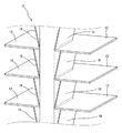
先ず、図1には、本発明に従うフィン・アンド・チューブ型熱交換器の実施形態の一つが、斜視図の状態において概略的に示されている。そこにおいて、熱交換器10は、互いに平行に且つ一定距離を隔てて積層、配置された複数枚のフィン12に対して、1本の扁平多穴管14が、かかるフィン12に設けられたスリット状の組付けスリット16に挿入された後、ろう付けによって固着されて、形成されている。
First, FIG. 1 schematically shows one embodiment of a fin-and-tube heat exchanger according to the present invention in a perspective view. In this case, the
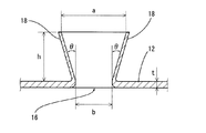
より詳細には、フィン12は、従来と同様に、アルミニウム若しくはアルミニウム合金からなる金属材料にて形成された、図2にも示されているように、矩形の平面形状を呈した薄肉の板状フィンとされている。そして、かかるフィン12の略中央部位には、扁平多穴管14が組み付けられる組付けスリット16が、矩形形状のフィン12の一方の辺の端部から対向する他方の辺に向かって延びるU字状のスリットとして、形成されている。更に、かかる組付けスリット16の周りには、所定高さで立設するカラー部18が、フィン12と一体的に形成されている。なお、かかるフィン12の厚さ(t)は、組み付けられる扁平多穴管14の大きさや、求められる熱交換器10の性能等に応じて、適宜に決定されるものであるが、好ましい一例としては、0.080mm以上、0.120mm以下の厚さとされることとなる。
More specifically, the
そして、かかる組付けスリット16の周縁部に形成されているカラー部18は、先端に向かうに従って扁平多穴管14との距離が漸次大きくなるように、基部から全体的に外方に所定角度:θにて傾斜せしめられていると共に、カラー部18の高さ:hは、熱交換器10における隣接するフィン12間の距離(設計値)となるように、構成されている。即ち、図3に拡大して示される如く、カラー部18の上方開口部の幅:aが、基部の幅:bよりも大きく(広く)されることによって、組付けスリット16の周縁部から立ち上がるカラー部18は、その先端に向かうに従って、組付けスリット16の外方に向かってフィン12の板面に対して角度:θをもって傾斜しており、そのようなカラー部18の高さ:hは、目的とする熱交換器10における隣接するフィン間の距離と同一とされているのである。
The
このように、カラー部18が、組付けスリット16の外方に向かって傾斜するように形成されていることにより、扁平多穴管14をフィン12の組付けスリット16に組付けると、カラー部18と扁平多穴管14との間に効果的な間隙が形成され、そのような状態でフィン12及び扁平多穴管14のろう付けを行うと、溶融したろう材は上記間隙内に浸入する。かかるろう材の浸入により、フィン12と扁平多穴管14との接合が充分に確保され、得られる熱交換器10は優れた伝熱性(熱交換性)を発揮することとなる。また、溶融したろう材が多少、多い場合であっても、上記間隙にて受け容れることが可能であるため、ろう付け不良に起因する隣接フィン間の距離の乱れ、換言すれば、ろう材が隣接するフィン12間の間隙に浸入し、隣接するフィン12同士を固着することによるフィン間の距離の乱れについても、その発生が効果的に抑制されるのである。
Thus, when the flat
また、カラー部18の高さ:hは、目的とする熱交換器10における隣接するフィン間の距離(設計値)とされていることから、そのようなカラー部18を有するフィン12を、その先端部が隣接するフィン12の下面(カラー部18が立設していない側の面)に当接するように扁平多穴管14との組付けを行い、かかる状態にてフィン12及び扁平多穴管14のろう付けを行うと、かかるろう付けの際に仮にフィンに予期しない外力が加えられた場合等であっても、フィン間の距離は十分に確保されることとなり、フィン間の距離の乱れの発生が効果的に抑制されるのである。
Further, since the height h of the
なお、カラー部18の傾斜角度:θは、好ましくは、5°〜45°の範囲内とされる。θが小さ過ぎると、不測の外力が加わった場合に目的とするフィン間の距離を確保することが出来ない恐れがあり、その一方でθが大き過ぎると、不測の外力が加わった場合にカラー部18が更に外方に開き、フィン間距離の乱れの発生を抑制することが困難となるからである。
The inclination angle θ of the
また、カラー部18の高さ:hは、一般に、1.2〜3.0mm程度とされる。カラー部18の高さが低すぎると、フィン間距離の乱れの発生を防止する効果が低くなってしまう恐れがあり、カラー部18の高さが高すぎると、後述するしごき加工等によってカラー部18の厚さが薄くなり、変形し易くなるため、フィン間距離の乱れの発生を抑制することが困難となるからである。
Further, the
ところで、このようなカラー部18が形成されたフィン12は、例えば、以下のような公知の加工方法によって有利に得ることが出来る。即ち、先ず、所定のアルミニウム若しくはアルミニウム合金からなるアルミニウム板材をプレス加工することによって、フィン12の外形形状とされ、更に、扁平多穴管14の外面形状に対応した組付けスリット16や、その組付けスリット部位の材料の切り起こしによって、かかる組付けスリット16の周縁部から所定高さで立設するカラー形成部が一体的に形成されたものが準備される。その後、そのようなカラー形成部に対してしごき加工を施し、更にカラー形成部の上方から所定の円錐状のパンチにてプレス加工を施すことにより、先端側部位が外方に向かって角度:θにて傾斜する、高さ:hのカラー部18が形成されるのである。
By the way, the
なお、カラー部18を形成する際のしごき加工は、最終的に与えられるカラー部18の高さ:hが、目的とするフィン間の距離(設計値)と同一となるように、1回若しくは複数回、実施される。1回のしごき加工は、50%以下のしごき率で実施されることが好ましい。しごき率とは、以下の式より算出されるものである。
[しごき率(%)]={(B−A)/B}×100(%) ・・・(式)
但し、Aはしごき加工後のカラー部の厚さであり、Bはしごき加工前のカラー部の 厚さである。
The ironing process for forming the
[Steeling rate (%)] = {(BA) / B} × 100 (%) (formula)
However, A is the thickness of the collar part after ironing, and B is the thickness of the collar part before ironing.
一方、扁平多穴管14は、アルミニウム若しくはアルミニウム合金からなる金属材料を用い、これにポートホール押出加工等の公知の加工方法を施すことによって、形成されることとなる。なお、図1においては、管軸方向に延びる7つの穴20が形成されてなる、扁平形状を呈する多穴管とされている。また、扁平多穴管14の厚さ:t’は、一般に、1.0〜4.0mm程度とされる。
On the other hand, the flat
そして、そのような扁平多穴管14とフィン12を用いて、かかるフィン12の複数枚を、それぞれに形成された組付けスリット16を一致させた状態下において、互いに平行に、且つカラー部18の先端が隣接するフィン12の下面(カラー部18が立設していない側の面)に当接するように配置せしめ、その一致させた組付けスリット16内に、扁平多穴管14を嵌め込んで、それらを組み付けた後に、置きろう等の方法にてろう付け加工を施すことにより、目的とするフィン・アンド・チューブ型熱交換器10が製作されるのである。なお、ここでは図示しないが、扁平多穴管14のそれぞれの両端部には、所定のヘッダがそれぞれ接続されて、扁平多穴管14の7つの穴20、即ち、管軸方向に延びる冷媒が流通せしめられる7つの流路が、冷媒の入口側と出口側においてそれぞれまとめられて、フィン・アンド・チューブ型熱交換器10として構成されている。
Then, using such a flat
このような本発明に従う構成とされたフィン・アンド・チューブ型熱交換器10によれば、カラー部18を、隣接するフィン12の下面(カラー部18が立設していない側の面)に当接させることにより、フィン間の距離が規定されるようにされているところから、仮にフィンと扁平多穴管とをろう付けする際に、フィンに予期しない外力が加えられた場合等であっても、フィン間の距離が十分に確保され、フィン間距離の乱れの発生が効果的に抑制されるのである。
According to the fin-and-
また、カラー部18は、外方に角度:θをもって傾斜せしめられていることから、カラー部18と扁平多穴管との間には間隙が形成され、そのような状態でフィン及び扁平多穴管のろう付けを行うと、溶融したろう材は上記間隙内に浸入する。このように、カラー部の先端側部位と扁平多穴管との間の間隙にろう材が浸入することにより、フィンと扁平多穴管との接合が充分なものとなるところから、得られる熱交換器は優れた伝熱性(熱交換性)を発揮することとなる。また、溶融したろう材が多少、多い場合であっても、上記間隙にて受け容れることが可能であるため、ろう付け不良に起因するフィン間距離の乱れの発生も、効果的に抑制され得るのである。
Further, since the
以上、本発明の代表的な実施形態の一つについて詳述してきたが、それは、あくまでも例示に過ぎないものであり、本発明は、そのような実施形態に係る具体的な記述によって、何等限定的に解釈されるものではないことが、理解されるべきである。 As described above, one of the representative embodiments of the present invention has been described in detail. However, this is merely an example, and the present invention is not limited in any way by the specific description according to such an embodiment. It should be understood that this is not to be construed as a matter of course.
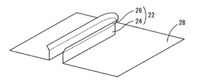
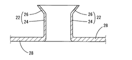
例えば、前述の実施形態において、カラー部18は、その基部から外方に向かって傾斜するものであるが、本発明においては、カラー部の少なくとも先端側部位が外方に向かって傾斜していれば足りる趣旨である。具体的には、図5及び図6に示されている如き、カラー部22が、フィン28の板面より直立する直立部24及び外方に傾斜する先端部26にて構成されているフィン28にあっても、本発明の熱交換器において採用することが出来る。
For example, in the above-described embodiment, the
また、上記した実施形態においては、側方開口空所形状の組付けスリットとして、U字形状を呈する組付けスリット16を例示したが、このような形状の他にも、例えば、コの字形状やV字形状等、組付けられる扁平多穴管14の厚さや外面形状に対応した形状の組付けスリット形状とすることも可能である。
Further, in the above-described embodiment, the U-shaped assembling slit 16 is illustrated as the side opening void-shaped assembling slit. However, in addition to such a shape, for example, a U-shaped It is also possible to adopt an assembling slit shape having a shape corresponding to the thickness or outer surface shape of the flat
さらに、フィン12と扁平多穴管14とをろう付けする方法として、置きろうによるろう付け方法を例示したが、そのような方法の他にも、例えば、アルミニウム板材の表面に予めろう材がクラッドされたもの、所謂ブレージングシートを用いて、フィン12を形成し、そのようなフィン12と扁平多穴管14とをろう付けする等、公知の各種のろう付け方法が採用可能であり、それら何れのろう付け方法においても、本発明の効果が、有利に発揮されることとなる。
Furthermore, as a method of brazing the
その他、一々列挙はしないが、本発明が、当業者の知識に基づいて、種々なる変更、修正、改良等を加えた態様において実施されるものであり、またそのような実施の態様が、本発明の趣旨を逸脱しない限りにおいて、何れも、本発明の範疇に属するものであることは、言うまでもないところである。 In addition, although not listed one by one, the present invention is implemented in a mode to which various changes, modifications, improvements and the like are added based on the knowledge of those skilled in the art. It goes without saying that any one of them falls within the scope of the present invention without departing from the spirit of the invention.
10 熱交換器 12 フィン
14 扁平多穴管 16 組付けスリット
18 カラー部 20 穴
22 カラー部 24 直立部
26 先端部 28 フィン
DESCRIPTION OF
Claims (4)
前記フィンの上面で前記組付けスリットの周りに立設されたカラー部の少なくとも先端側部位を外方に傾斜せしめ、その傾斜部位の先端部を隣接するフィンの下面に当接させることにより、隣接するフィン間の距離が規定されるようにしたことを特徴とするフィン・アンド・チューブ型熱交換器。 Assembling slits in the shape of side openings are provided in a large number of plate-like fins made of aluminum or an alloy thereof laminated at a predetermined distance from each other so as to open at their corresponding peripheral edges. On the other hand, a flat multi-hole tube made of aluminum or an alloy thereof is fitted into a fin-and-tube heat exchanger assembled,
By adhering at least the tip side portion of the collar portion erected on the upper surface of the fin around the assembly slit to the outside and bringing the tip portion of the inclined portion into contact with the lower surface of the adjacent fin, A fin-and-tube heat exchanger characterized in that the distance between the fins is defined.
The fin-and-tube heat exchanger according to any one of claims 1 to 3, wherein the assembly slit is formed in a U-shape.
Priority Applications (1)
| Application Number | Priority Date | Filing Date | Title |
|---|---|---|---|
| JP2011065290A JP2012202572A (en) | 2011-03-24 | 2011-03-24 | Fin-and-tube heat exchanger |
Applications Claiming Priority (1)
| Application Number | Priority Date | Filing Date | Title |
|---|---|---|---|
| JP2011065290A JP2012202572A (en) | 2011-03-24 | 2011-03-24 | Fin-and-tube heat exchanger |
Publications (1)
| Publication Number | Publication Date |
|---|---|
| JP2012202572A true JP2012202572A (en) | 2012-10-22 |
Family
ID=47183771
Family Applications (1)
| Application Number | Title | Priority Date | Filing Date |
|---|---|---|---|
| JP2011065290A Withdrawn JP2012202572A (en) | 2011-03-24 | 2011-03-24 | Fin-and-tube heat exchanger |
Country Status (1)
| Country | Link |
|---|---|
| JP (1) | JP2012202572A (en) |
Cited By (2)
| Publication number | Priority date | Publication date | Assignee | Title |
|---|---|---|---|---|
| JP2016121838A (en) * | 2014-12-25 | 2016-07-07 | 株式会社富士通ゼネラル | Heat exchanger |
| CN108981417A (en) * | 2018-10-12 | 2018-12-11 | 泰铂(上海)环保科技股份有限公司 | A kind of air-conditioning pipe type heat exchanger and its processing method |
-
2011
- 2011-03-24 JP JP2011065290A patent/JP2012202572A/en not_active Withdrawn
Cited By (2)
| Publication number | Priority date | Publication date | Assignee | Title |
|---|---|---|---|---|
| JP2016121838A (en) * | 2014-12-25 | 2016-07-07 | 株式会社富士通ゼネラル | Heat exchanger |
| CN108981417A (en) * | 2018-10-12 | 2018-12-11 | 泰铂(上海)环保科技股份有限公司 | A kind of air-conditioning pipe type heat exchanger and its processing method |
Similar Documents
| Publication | Publication Date | Title |
|---|---|---|
| US7111670B2 (en) | Plate fin for heat exchanger and heat exchanger core | |
| EP2447659A2 (en) | Heat exchanger and fin for the same | |
| US20150033789A1 (en) | Heat exchanger and air conditioner provided with heat exchanger | |
| US20060175047A1 (en) | Heat exchanger, method of manufacturing heat exchanger and plate-shaped fin for heat exchanger | |
| JPWO2014091782A1 (en) | Flat tube heat exchanger and air conditioner outdoor unit equipped with the same | |
| JP2012247091A (en) | Fin and tube type heat exchanger | |
| JP2011127867A (en) | Heat exchanger fin, heat exchanger, and method for manufacturing the same | |
| US20200318911A1 (en) | Heat exchangers having brazed tube-to-fin joints and methods of producing the same | |
| JP6123193B2 (en) | Refrigerant heat exchanger | |
| JP2007155181A (en) | Heat exchanger | |
| JP2012172892A (en) | Fin and tube type heat exchanger | |
| JP2004020174A (en) | Flat radiating fin, heat exchanger using it, and its manufacturing method | |
| EP2447660A2 (en) | Heat Exchanger and Micro-Channel Tube Thereof | |
| JP6674262B2 (en) | Heat exchanger and method of manufacturing the same | |
| JP2014169851A (en) | Heat exchanger | |
| JP2012202572A (en) | Fin-and-tube heat exchanger | |
| WO2020095797A1 (en) | Heat exchanger and method for manufacturing heat exchanger | |
| JP2008215670A (en) | Heat transfer fin, fin tube-type heat exchanger and refrigerating cycle device | |
| JP2016097434A (en) | Tube for heat exchanger and its manufacturing method | |
| JP2011257084A (en) | All-aluminum heat exchanger | |
| JP2012237538A (en) | Heat exchanger | |
| JPH1038487A (en) | Heat exchanger and its manufacture | |
| JP2004279025A (en) | Cross fin tube type heat exchanger | |
| JP2013011401A (en) | Heat exchanger, refrigeration cycle circuit using the same, refrigerator and air conditioner using the refrigeration cycle circuit | |
| JP2011185589A (en) | Serpentine heat exchanger for air conditioner |
Legal Events
| Date | Code | Title | Description |
|---|---|---|---|
| A711 | Notification of change in applicant |
Free format text: JAPANESE INTERMEDIATE CODE: A712 Effective date: 20131023 |
|
| A300 | Withdrawal of application because of no request for examination |
Free format text: JAPANESE INTERMEDIATE CODE: A300 Effective date: 20140603 |