JP5127736B2 - 事故箇所検出システム及び事故区間特定方法 - Google Patents
事故箇所検出システム及び事故区間特定方法 Download PDFInfo
- Publication number
- JP5127736B2 JP5127736B2 JP2009023059A JP2009023059A JP5127736B2 JP 5127736 B2 JP5127736 B2 JP 5127736B2 JP 2009023059 A JP2009023059 A JP 2009023059A JP 2009023059 A JP2009023059 A JP 2009023059A JP 5127736 B2 JP5127736 B2 JP 5127736B2
- Authority
- JP
- Japan
- Prior art keywords
- coil
- accident
- magnetic field
- tower
- fault
- Prior art date
- Legal status (The legal status is an assumption and is not a legal conclusion. Google has not performed a legal analysis and makes no representation as to the accuracy of the status listed.)
- Expired - Fee Related
Links
- 238000001514 detection method Methods 0.000 title claims description 50
- 238000000034 method Methods 0.000 title claims description 19
- 229910000831 Steel Inorganic materials 0.000 claims description 39
- 239000010959 steel Substances 0.000 claims description 39
- 230000008859 change Effects 0.000 claims description 6
- 238000006243 chemical reaction Methods 0.000 claims description 6
- 230000005674 electromagnetic induction Effects 0.000 claims description 5
- 238000010586 diagram Methods 0.000 description 6
- 238000009434 installation Methods 0.000 description 6
- 230000004907 flux Effects 0.000 description 5
- 238000005259 measurement Methods 0.000 description 5
- 238000012423 maintenance Methods 0.000 description 4
- NJPPVKZQTLUDBO-UHFFFAOYSA-N novaluron Chemical compound C1=C(Cl)C(OC(F)(F)C(OC(F)(F)F)F)=CC=C1NC(=O)NC(=O)C1=C(F)C=CC=C1F NJPPVKZQTLUDBO-UHFFFAOYSA-N 0.000 description 4
- 230000005540 biological transmission Effects 0.000 description 2
- 230000008569 process Effects 0.000 description 2
- 230000001902 propagating effect Effects 0.000 description 2
- 230000008878 coupling Effects 0.000 description 1
- 238000010168 coupling process Methods 0.000 description 1
- 238000005859 coupling reaction Methods 0.000 description 1
- 230000006698 induction Effects 0.000 description 1
- 230000001939 inductive effect Effects 0.000 description 1
- 230000004044 response Effects 0.000 description 1
Images


Classifications
-
- Y—GENERAL TAGGING OF NEW TECHNOLOGICAL DEVELOPMENTS; GENERAL TAGGING OF CROSS-SECTIONAL TECHNOLOGIES SPANNING OVER SEVERAL SECTIONS OF THE IPC; TECHNICAL SUBJECTS COVERED BY FORMER USPC CROSS-REFERENCE ART COLLECTIONS [XRACs] AND DIGESTS
- Y04—INFORMATION OR COMMUNICATION TECHNOLOGIES HAVING AN IMPACT ON OTHER TECHNOLOGY AREAS
- Y04S—SYSTEMS INTEGRATING TECHNOLOGIES RELATED TO POWER NETWORK OPERATION, COMMUNICATION OR INFORMATION TECHNOLOGIES FOR IMPROVING THE ELECTRICAL POWER GENERATION, TRANSMISSION, DISTRIBUTION, MANAGEMENT OR USAGE, i.e. SMART GRIDS
- Y04S10/00—Systems supporting electrical power generation, transmission or distribution
- Y04S10/50—Systems or methods supporting the power network operation or management, involving a certain degree of interaction with the load-side end user applications
- Y04S10/52—Outage or fault management, e.g. fault detection or location
Landscapes
- Emergency Protection Circuit Devices (AREA)
- Locating Faults (AREA)
Description
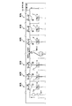
なお、コイルC3は図示されているが、原理的には使用しない。
12 電圧判定部
13 A/D変換部
14 実効値継続時間計測部
15 自鉄塔事故判定部
16 電流方向判定部
C1 コイル(第1のコイル)
C2 コイル(第2のコイル)
C3 コイル(第3のコイル)
EW 電力線
Claims (5)
- 鉄塔に架設される電力線に発生した事故の箇所を検出する事故箇所検出システムであって、
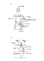
前記鉄塔のうち、地面の近くにおいて、前記電力線を流れる故障サージ電流の方向及び前記鉄塔の塔脚を流れる誘導サージ電流の方向の両方向に対して垂直に設置され、前記故障サージ電流及び前記誘導サージ電流による磁界である第1のサージ磁界を検出する第1のコイルと、
前記鉄塔のうち、地面の近くにおいて、前記故障サージ電流の方向に平行に、かつ、前記誘導サージ電流の方向に垂直に設置され、前記誘導サージ電流による磁界である第2のサージ磁界を検出する第2のコイルと、
前記第1のコイルの検出した前記第1のサージ磁界と、前記第2のコイルの検出した前記第2のサージ磁界との差分に基づいて、前記故障サージ電流の方向を判定する電流方向判定部と、
を備えることを特徴とする事故箇所検出システム。 - 請求項1に記載の事故箇所検出システムであって、
前記電流方向判定部は、
前記第1のコイルが前記第1のサージ磁界の変化に伴って出力する電圧と、前記第2のコイルが前記第2のサージ磁界の変化に伴って出力する電圧との差分をとり、その差分の正負に従って前記故障サージ電流の方向を判定する
ことを特徴とする事故箇所検出システム。 - 請求項1又は請求項2に記載の事故箇所検出システムであって、
前記鉄塔のうち、地面の近くにおいて、前記故障サージ電流の方向に平行に、かつ、前記鉄塔の塔脚を流れる商用周波電流の方向に垂直に設置され、前記商用周波電流による磁界である商用周波磁界を検出し、第1の電圧を出力する第3のコイルと、
前記第3のコイルの出力した前記第1の電圧をA/D変換し、第2の電圧として出力するA/D変換器と、
前記A/D変換器の出力した第2の電圧の実効値が所定値以上である状態が、所定時間以上継続した場合に、当該第3のコイルの設置された鉄塔において事故が発生したと判定する自鉄塔事故判定部と、
をさらに備えることを特徴とする事故箇所検出システム。 - 請求項1ないし請求項3のいずれか一項に記載の事故箇所検出システムであって、
前記第1のコイルと、前記第2のコイルとは、前記塔脚の軸を中心とする同心円上に設置され、かつ、同じ電磁誘導特性を有する
ことを特徴とする事故箇所検出システム。 - 請求項1ないし請求項4のいずれか一項に記載の事故箇所検出システムを用いて、前記電力線における事故区間を特定する事故区間特定方法であって、
連なる複数の前記鉄塔ごとに、当該鉄塔のうち、地面の近くに前記第1のコイル及び前記第2のコイルを設置するステップと、
前記電力線に事故が発生した場合に、前記鉄塔ごとの前記電流方向判定部が判定した前記故障サージ電流の方向を取得するステップと、
隣接する2つの鉄塔に係る前記電流方向判定部が判定した前記故障サージ電流の方向が反転したときに、当該2つの鉄塔の間を事故区間として特定するステップと、
を実行することを特徴とする事故区間特定方法。
Priority Applications (1)
| Application Number | Priority Date | Filing Date | Title |
|---|---|---|---|
| JP2009023059A JP5127736B2 (ja) | 2009-02-03 | 2009-02-03 | 事故箇所検出システム及び事故区間特定方法 |
Applications Claiming Priority (1)
| Application Number | Priority Date | Filing Date | Title |
|---|---|---|---|
| JP2009023059A JP5127736B2 (ja) | 2009-02-03 | 2009-02-03 | 事故箇所検出システム及び事故区間特定方法 |
Publications (2)
| Publication Number | Publication Date |
|---|---|
| JP2010183678A JP2010183678A (ja) | 2010-08-19 |
| JP5127736B2 true JP5127736B2 (ja) | 2013-01-23 |
Family
ID=42764756
Family Applications (1)
| Application Number | Title | Priority Date | Filing Date |
|---|---|---|---|
| JP2009023059A Expired - Fee Related JP5127736B2 (ja) | 2009-02-03 | 2009-02-03 | 事故箇所検出システム及び事故区間特定方法 |
Country Status (1)
| Country | Link |
|---|---|
| JP (1) | JP5127736B2 (ja) |
Cited By (1)
| Publication number | Priority date | Publication date | Assignee | Title |
|---|---|---|---|---|
| CN105277854A (zh) * | 2015-11-18 | 2016-01-27 | 国网冀北电力有限公司唐山供电公司 | 一种避雷器接地指示器及避雷器接地指示方法 |
Families Citing this family (1)
| Publication number | Priority date | Publication date | Assignee | Title |
|---|---|---|---|---|
| CN111273078B (zh) * | 2020-03-01 | 2022-07-01 | 武汉知仁测控科技有限公司 | 一种高压输电铁塔雷击指示器 |
Family Cites Families (4)
| Publication number | Priority date | Publication date | Assignee | Title |
|---|---|---|---|---|
| JPH03186774A (ja) * | 1989-12-15 | 1991-08-14 | Sumitomo Electric Ind Ltd | 送電線事故鉄塔標定装置 |
| JP2711192B2 (ja) * | 1991-09-12 | 1998-02-10 | 株式会社フジクラ | 送電線路の事故発生区間の標定方法 |
| JPH06230065A (ja) * | 1993-01-29 | 1994-08-19 | Sumitomo Electric Ind Ltd | 架空送電線の事故区間検出方法 |
| JP2004053361A (ja) * | 2002-07-18 | 2004-02-19 | Tomita Denki Seisakusho:Kk | 電流検出システム |
-
2009
- 2009-02-03 JP JP2009023059A patent/JP5127736B2/ja not_active Expired - Fee Related
Cited By (2)
| Publication number | Priority date | Publication date | Assignee | Title |
|---|---|---|---|---|
| CN105277854A (zh) * | 2015-11-18 | 2016-01-27 | 国网冀北电力有限公司唐山供电公司 | 一种避雷器接地指示器及避雷器接地指示方法 |
| CN105277854B (zh) * | 2015-11-18 | 2017-07-04 | 国网冀北电力有限公司唐山供电公司 | 一种避雷器接地指示器 |
Also Published As
| Publication number | Publication date |
|---|---|
| JP2010183678A (ja) | 2010-08-19 |
Similar Documents
| Publication | Publication Date | Title |
|---|---|---|
| EP2821800B1 (en) | Current detection device | |
| JP5714943B2 (ja) | 波形記録装置、及び故障点標定システム | |
| CN103558507A (zh) | 用于直流接地选线和交流窜入选线的传感器 | |
| JP2013231720A (ja) | アーク故障検出装置及び方法 | |
| CN102624325A (zh) | 具有电流传感器的扼流器 | |
| JP5162376B2 (ja) | 電流センサ、電力量計 | |
| JP5127736B2 (ja) | 事故箇所検出システム及び事故区間特定方法 | |
| JP6092519B2 (ja) | 地絡検出装置および地絡検出方法 | |
| JP6461698B2 (ja) | 漏電検出装置及び漏電検出方法 | |
| KR100592845B1 (ko) | 가공 송전선 낙뢰 및 사고지점 검출 장치 | |
| KR100645167B1 (ko) | 가공 송전선 낙뢰 및 사고지점 검출장치 | |
| JP5422220B2 (ja) | 故障検出器、故障検出システム及び故障検出方法 | |
| JP2018028501A (ja) | 欠相検知システム、欠相検知装置および欠相検知方法 | |
| JP2006266709A (ja) | 碍子漏洩電流測定装置 | |
| JPH09236629A (ja) | 送電線の地絡鉄塔検出方法および装置 | |
| JP6263050B2 (ja) | 地絡検出装置 | |
| CN1054483C (zh) | 大功率整流设备支路故障信号检测器 | |
| JPH099439A (ja) | ケーブル識別装置及びそれに使用できる電流センサー | |
| JP4334307B2 (ja) | 交流き電回路用事故点標定装置 | |
| JP3232520U (ja) | 電流検出用センサ、及び地絡点標定システム | |
| JPH06273470A (ja) | 架空送電線の事故区間標定装置 | |
| CN203688721U (zh) | 用于直流接地选线和交流窜入选线的传感器 | |
| CN116420088B (zh) | 对电线圈装置的运行的监视 | |
| EP4053575B1 (en) | LEAKAGE CURRENT DETECTION IN CABLE TRAYS | |
| CN210039896U (zh) | 防铁芯多点接地的电压互感器 |
Legal Events
| Date | Code | Title | Description |
|---|---|---|---|
| A621 | Written request for application examination |
Free format text: JAPANESE INTERMEDIATE CODE: A621 Effective date: 20101215 |
|
| A977 | Report on retrieval |
Free format text: JAPANESE INTERMEDIATE CODE: A971007 Effective date: 20120813 |
|
| TRDD | Decision of grant or rejection written | ||
| A01 | Written decision to grant a patent or to grant a registration (utility model) |
Free format text: JAPANESE INTERMEDIATE CODE: A01 Effective date: 20121023 |
|
| A01 | Written decision to grant a patent or to grant a registration (utility model) |
Free format text: JAPANESE INTERMEDIATE CODE: A01 |
|
| A61 | First payment of annual fees (during grant procedure) |
Free format text: JAPANESE INTERMEDIATE CODE: A61 Effective date: 20121030 |
|
| R150 | Certificate of patent or registration of utility model |
Free format text: JAPANESE INTERMEDIATE CODE: R150 Ref document number: 5127736 Country of ref document: JP Free format text: JAPANESE INTERMEDIATE CODE: R150 |
|
| FPAY | Renewal fee payment (event date is renewal date of database) |
Free format text: PAYMENT UNTIL: 20151109 Year of fee payment: 3 |
|
| FPAY | Renewal fee payment (event date is renewal date of database) |
Free format text: PAYMENT UNTIL: 20151109 Year of fee payment: 3 |
|
| R250 | Receipt of annual fees |
Free format text: JAPANESE INTERMEDIATE CODE: R250 |
|
| R250 | Receipt of annual fees |
Free format text: JAPANESE INTERMEDIATE CODE: R250 |
|
| R250 | Receipt of annual fees |
Free format text: JAPANESE INTERMEDIATE CODE: R250 |
|
| R250 | Receipt of annual fees |
Free format text: JAPANESE INTERMEDIATE CODE: R250 |
|
| LAPS | Cancellation because of no payment of annual fees |