JP5124579B2 - Surface sensing device - Google Patents
Surface sensing device Download PDFInfo
- Publication number
- JP5124579B2 JP5124579B2 JP2009527191A JP2009527191A JP5124579B2 JP 5124579 B2 JP5124579 B2 JP 5124579B2 JP 2009527191 A JP2009527191 A JP 2009527191A JP 2009527191 A JP2009527191 A JP 2009527191A JP 5124579 B2 JP5124579 B2 JP 5124579B2
- Authority
- JP
- Japan
- Prior art keywords
- probe
- rotation
- axis
- support
- sensing device
- Prior art date
- Legal status (The legal status is an assumption and is not a legal conclusion. Google has not performed a legal analysis and makes no representation as to the accuracy of the status listed.)
- Active
Links
- 239000000523 sample Substances 0.000 claims abstract description 179
- 238000000034 method Methods 0.000 claims description 13
- 230000003213 activating effect Effects 0.000 claims description 2
- 241001422033 Thestylus Species 0.000 description 56
- 238000010586 diagram Methods 0.000 description 6
- 230000003287 optical effect Effects 0.000 description 6
- 229910003460 diamond Inorganic materials 0.000 description 4
- 239000010432 diamond Substances 0.000 description 4
- 125000006850 spacer group Chemical group 0.000 description 4
- 230000008901 benefit Effects 0.000 description 3
- 238000006073 displacement reaction Methods 0.000 description 2
- 230000004886 head movement Effects 0.000 description 2
- 238000007689 inspection Methods 0.000 description 2
- 238000005259 measurement Methods 0.000 description 2
- 230000001939 inductive effect Effects 0.000 description 1
- 239000000463 material Substances 0.000 description 1
- 230000013011 mating Effects 0.000 description 1
Images


Classifications
-
- G—PHYSICS
- G01—MEASURING; TESTING
- G01B—MEASURING LENGTH, THICKNESS OR SIMILAR LINEAR DIMENSIONS; MEASURING ANGLES; MEASURING AREAS; MEASURING IRREGULARITIES OF SURFACES OR CONTOURS
- G01B5/00—Measuring arrangements characterised by the use of mechanical techniques
- G01B5/004—Measuring arrangements characterised by the use of mechanical techniques for measuring coordinates of points
- G01B5/008—Measuring arrangements characterised by the use of mechanical techniques for measuring coordinates of points using coordinate measuring machines
- G01B5/012—Contact-making feeler heads therefor
-
- G—PHYSICS
- G01—MEASURING; TESTING
- G01B—MEASURING LENGTH, THICKNESS OR SIMILAR LINEAR DIMENSIONS; MEASURING ANGLES; MEASURING AREAS; MEASURING IRREGULARITIES OF SURFACES OR CONTOURS
- G01B7/00—Measuring arrangements characterised by the use of electric or magnetic techniques
- G01B7/004—Measuring arrangements characterised by the use of electric or magnetic techniques for measuring coordinates of points
- G01B7/008—Measuring arrangements characterised by the use of electric or magnetic techniques for measuring coordinates of points using coordinate measuring machines
- G01B7/012—Contact-making feeler heads therefor
Landscapes
- Physics & Mathematics (AREA)
- General Physics & Mathematics (AREA)
- A Measuring Device Byusing Mechanical Method (AREA)
- Length Measuring Devices With Unspecified Measuring Means (AREA)
- Machine Tool Sensing Apparatuses (AREA)
- Analysing Materials By The Use Of Radiation (AREA)
- Switches Operated By Changes In Physical Conditions (AREA)
Abstract
Description
本発明は、例えば、三次元座標測定機(CMM)、スキャンニング機械、工作機械、あるいは検査/測定ロボットのような、位置決め装置において使用するための表面感知デバイスに関する。 The present invention relates to a surface sensing device for use in a positioning device, such as, for example, a coordinate measuring machine (CMM), a scanning machine, a machine tool, or an inspection / measurement robot.
そのような位置決め機械(例えばCMMを示す特許文献1を見よ)は、被加工物を測定するために用いられ、典型的には、被加工物が支持されるテーブルに対して3方向x、y、zに移動可能なアームを備える。方向x、y、zの各々に関するアームの移動は、その機械上のトランスデューサーによって測定され、アームに設けられたプローブが測定される被加工物の表面とアームとの間の関係を示す信号を生み出す。したがって、その表面の位置は、測定され得る。 Such a positioning machine (see, for example, US Pat. No. 6,057,086 showing CMM) is used to measure a workpiece, typically in three directions x, y with respect to a table on which the workpiece is supported. , Z is provided with a movable arm. The movement of the arm in each of the directions x, y, z is measured by a transducer on the machine and a signal indicating the relationship between the surface of the workpiece and the arm on which the probe provided on the arm is measured. produce. Thus, the position of the surface can be measured.
代わりの機械において、例えば、幾つかの種類の工作機械において、テーブルは、xおよびyに関して動き、アームはzに関して動く。 In alternative machines, for example in some types of machine tools, the table moves with respect to x and y and the arm moves with respect to z.
特許文献2に示されているように、三次元座標測定機に取り付けられる、スキャンニングプローブ装置を提供することは知られている。そのようなスキャンニングプローブ装置は、固定構造物に対して、相互に直交する2つの軸に関して回転可能であるプローブヘッドと、そして、スタイラスを含むプローブアッセンブリとを備える。使用に際して、ヘッドは機械のアームに取り付けられ、それの軸の一方はアームの軸に合わせられる。ヘッドの回転可能な軸の各々に関係付けられたトランスデューサーは、機械のアームの軸に対してプローブアッセンブリの軸の方向を決める。
As shown in
既知のプローブヘッドの別の例が、レニショウのPH9である。PH9は、モーター駆動の2軸プローブヘッドであり、それは2つの直列的に接続されたローターによってプローブを方向付ける。ローターの各々は、回転のそれの軸に関して等間隔の、複数の運動学的な静止位置のうちの1つを占めることができる。特許文献3は、コンピュータ制御を有さない機械上で使用するための、このプローブヘッドの手動で動作可能なバージョンに関する。 Another example of a known probe head is Renishaw PH9. The PH9 is a motor driven biaxial probe head that directs the probe by two serially connected rotors. Each of the rotors can occupy one of a plurality of kinematic rest positions that are equally spaced about its axis of rotation. U.S. Patent No. 6,099,059 relates to a manually operable version of this probe head for use on a machine without computer control.
スキャニング作業の間、機械および/またはプローブヘッドは、被加工物の表面に関するデータを集めるように、機械制御装置からの指示にしたがって、スタイラス先端部に、被加工物の表面上を動くことをもたらす。機械やプローブヘッドの測定トランスデューサーによって提供される信号、および、表面感知デバイスの寸法についての情報から、予測が、スタイラス先端部の位置(そしてひいては表面の位置)に関してなされ得る。典型的な被加工物は、例えば、種々の角度の多くの穴を有する、車のエンジンブロックであり得る。被加工物の全表面から情報を得ることが望ましく、それ故、スタイラスは、表面の全てに達することができなければならない。 During the scanning operation, the machine and / or probe head causes the stylus tip to move over the workpiece surface in accordance with instructions from the machine controller to collect data about the workpiece surface. . From the signals provided by the measurement transducers of the machine and probe head and information about the dimensions of the surface sensing device, predictions can be made regarding the position of the stylus tip (and thus the position of the surface). A typical workpiece may be, for example, a car engine block having many holes of various angles. It is desirable to obtain information from the entire surface of the workpiece, so the stylus must be able to reach all of the surface.
多くのプローブ、例えば、接触トリガープローブのようなボールスタイラスを有するそれらは、多方向性である。これは、それらが多くの方向において被加工物を検知することができるということを意味する。しかし、光学プローブおよび表面仕上げプローブのような、幾つかのプローブは、一方向だけに作用する。これは、それらが一方向においてのみ被加工物を検知することができ、それらが達することができる表面の数を限定することを意味する。 Many probes, for example those with a ball stylus such as a contact trigger probe, are multi-directional. This means that they can detect the workpiece in many directions. However, some probes, such as optical probes and surface finish probes, only work in one direction. This means that they can only detect workpieces in one direction and limit the number of surfaces they can reach.
被加工物の変化する形状、および、プローブヘッドの動きの物理的範囲や制限のために、スタイラス先端部は、ときどき、被加工物の表面に達することができない。したがって、表面の外形に関する情報を得ることができない。 Due to the changing shape of the workpiece and the physical range and limitations of probe head movement, the stylus tip sometimes cannot reach the surface of the workpiece. Therefore, information regarding the outer shape of the surface cannot be obtained.
本発明の第1態様は、
機械の可動アームに支持体を取り付けるための取付手段と、
第1回転軸まわりに取付手段に対して回転可能である第1部材であって、前記回転が第1モーターによって生じさせられる第1部材と、第2回転軸まわりに第1部材に対して回転可能である第2部材であって、前記回転が第2モーターによって生じさせられる第2部材とを有する支持体であって、第2回転軸は、第1回転軸を横切り、表面感知デバイスが、第2部材に、それとともに回転するために取り付けられる、支持体と、
被加工物の表面を感知するための表面感知デバイスと、
第3回転軸まわりの支持体に対する表面感知デバイスの回転を可能にするための回転手段であって、第3回転軸は第1回転軸と合わさることが可能である、回転手段と
を備え、
第1回転軸および第3回転軸が合わせられるとき、表面感知デバイスに対する支持体の回転は、第1モーターによって作動可能であることを特徴とする、
被加工物の表面を測定するための装置を提供する。
The first aspect of the present invention is:
Attachment means for attaching the support to the movable arm of the machine;
A first member rotatable about the first rotation axis relative to the attachment means, wherein the rotation is caused by the first motor, and the first member rotates about the second rotation axis with respect to the first member; A second member that is capable of being rotated by a second motor, wherein the second rotational axis crosses the first rotational axis, and the surface sensing device comprises: A support attached to the second member for rotation therewith;
A surface sensing device for sensing the surface of the workpiece;
Rotation means for allowing rotation of the surface sensing device relative to the support about the third rotation axis, the third rotation axis comprising a rotation means capable of mating with the first rotation axis;
When the first rotation axis and the third rotation axis are aligned, the rotation of the support relative to the surface sensing device is operable by the first motor,
An apparatus for measuring the surface of a workpiece is provided.
好ましくは、ホルダーが、表面感知デバイスに対する支持体の前記回転の間、表面感知デバイスを動かないように保持するために提供される。 Preferably, a holder is provided to hold the surface sensing device stationary during the rotation of the support relative to the surface sensing device.
有利には、ピンが、ホルダーおよび表面感知デバイスの一方に設けられ、表面感知デバイスに対する支持体の回転の間、表面感知デバイスを動かないように保持するために、ホルダーおよび表面感知デバイスの他方に関する少なくとも1つの凹部と係合可能である。 Advantageously, a pin is provided on one of the holder and the surface sensing device and relates to the other of the holder and the surface sensing device in order to hold the surface sensing device stationary during rotation of the support relative to the surface sensing device. Engageable with at least one recess.
好ましくは、支持体の第1回転軸および第2回転軸は、直交する。 Preferably, the first rotation axis and the second rotation axis of the support are orthogonal to each other.
有利には、表面感知デバイスの第3回転軸は、支持体の第2軸に交わる。 Advantageously, the third axis of rotation of the surface sensing device intersects the second axis of the support.
ある場合には、表面感知デバイスの第3回転軸は、表面感知デバイスの概ね長手方向の軸である。しかし、代わりに、第3軸は、例えば、表面感知デバイスの長手方向軸に対してある角度をなしてもよい。 In some cases, the third rotational axis of the surface sensing device is a generally longitudinal axis of the surface sensing device. Alternatively, however, the third axis may be at an angle with respect to the longitudinal axis of the surface sensing device, for example.
プローブあるいはスタイラスの第3軸まわりの回転は、単一方向性プローブによってアクセスされ得る表面の数を増すので、単一方向性プローブに、多方向のプローブとして働くことを可能にし得る。 Rotation of the probe or stylus around the third axis may increase the number of surfaces that can be accessed by the unidirectional probe, thus allowing the unidirectional probe to act as a multidirectional probe.
幾つかの実施形態では、表面感知デバイスは、第3回転軸に対して横切る方向における表面あるいは第3回転軸からずれた表面を感知する。別の実施形態では、表面感知デバイスは、例えば、表面感知デバイスの第3軸の方向において、感知することができる。 In some embodiments, the surface sensing device senses a surface in a direction transverse to or relative to the third rotational axis. In another embodiment, the surface sensing device can sense, for example, in the direction of the third axis of the surface sensing device.
表面感知デバイスは、接触プローブあるいは非接触プローブであり得る。非接触プローブは、例えば、光学プローブ、容量性プローブ、および誘導性プローブを含む。 The surface sensing device can be a contact probe or a non-contact probe. Non-contact probes include, for example, optical probes, capacitive probes, and inductive probes.
好都合なことには、表面感知デバイスは、プローブ本体、スタイラス、およびスタイラス先端部を備える。 Conveniently, the surface sensing device comprises a probe body, a stylus and a stylus tip.
有利には、表面感知デバイスは、表面仕上げプローブを備える。一方、表面感知デバイスは、例えば、レーザースポットプローブ、あるいは、レーザー線プローブを備えることができる。 Advantageously, the surface sensing device comprises a surface finishing probe. On the other hand, the surface sensing device can include, for example, a laser spot probe or a laser beam probe.
好ましくは、回転手段は、デバイスに、最大で360度まで、360度を含めて、回転することを可能にする。しかし、回転手段は、デバイスに、360度を越えてまで回転することを可能にしてもよい。代わりに、例えば、プローブとプローブヘッドとの間の電気接触を提供するべくスリップリングを使用することによって、端部停止部なしに、それを連続して回転することを可能にしてもよい。 Preferably, the rotating means allows the device to rotate up to 360 degrees, including 360 degrees. However, the rotating means may allow the device to rotate beyond 360 degrees. Alternatively, it may be possible to rotate it continuously without an end stop, for example by using a slip ring to provide electrical contact between the probe and the probe head.
好都合なことには、回転手段は、付加的に手動で作動可能である。 Conveniently, the rotating means can additionally be manually activated.
本発明の第2態様は、被加工物の表面を測定するための装置を用いるための方法であって、その装置は、支持体と、機械の可動アームに支持体を取り付けるための取付手段と、被加工物の表面を感知するための表面感知デバイスと、第1回転軸まわりに取付手段に対して回転可能であって第1モーターによって動かされる第1部材と、第2回転軸まわりに第1部材に対して回転可能であって第2モーターによって動かされる第2部材とを有する支持体であって、第2回転軸は、第1回転軸を横切り、表面感知デバイスが、第2部材に、それとともに回転するために取り付けられる、支持体と、第3回転軸まわりの支持体に対する表面感知デバイスの回転を可能にするための回転手段であって、第3回転軸は第1回転軸と合わさることが可能である、回転手段とを備え、
該方法は、
第1回転軸および第3回転軸を合わせるステップと、そして、
表面感知デバイスに対する支持体の回転を作動させるように、第1モーターを作動させるステップと
を含むことを特徴とする、方法を提供する。
A second aspect of the invention is a method for using an apparatus for measuring the surface of a workpiece, the apparatus comprising a support and attachment means for attaching the support to a movable arm of a machine. A surface sensing device for sensing the surface of the workpiece, a first member rotatable about the first rotation axis relative to the attachment means and moved by the first motor, and a second member about the second rotation axis. And a second member that is rotatable relative to one member and that is moved by a second motor, wherein the second rotational axis crosses the first rotational axis, and the surface sensing device is attached to the second member. A support attached for rotation therewith and a rotation means for allowing rotation of the surface sensing device relative to the support about the third rotation axis, wherein the third rotation axis is the first rotation axis; Can be combined That, a rotation means,
The method
Aligning the first rotation axis and the third rotation axis; and
Activating a first motor to actuate rotation of the support relative to the surface sensing device.
好都合なことには、方法は、被加工物の表面に沿ってデバイスを動かすステップと、そして、被加工物の表面に関する情報を集めるステップとをさらに含む。 Conveniently, the method further comprises moving the device along the surface of the workpiece and collecting information about the surface of the workpiece.
好ましくは、被加工物の表面を測定することは、被加工物の表面をスキャンすることを含む。 Preferably, measuring the surface of the workpiece includes scanning the surface of the workpiece.
さて、本発明の好ましい実施形態は、例として、添付図面を参照して説明されるだろう。 Preferred embodiments of the present invention will now be described by way of example with reference to the accompanying drawings.
図1を参照して、座標位置決め機械における座標系が、相互に直交する3つの軸、1A、2Aおよび3Aによって定められ得、使用に際して、1Aは実質的に垂直であり、3Aは実質的に水平である。軸1Aが紙面において0度に位置するようにとられる場合、前記0度の位置から、また紙面において90度の位置までの動きは、軸2Aに関しての反時計方向の回転によってもたらされ得る。
Referring to FIG. 1, a coordinate system in a coordinate positioning machine can be defined by three
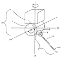
図1は、3次元において本発明の好ましい実施形態を示し、図2は、図1の軸1A、2Aによって定められる平面における装置を通しての断面を示す。支持体7、この場合、有機的に統合されたプローブヘッドは、第1ハウジング部材1および第2ハウジング部材2をそれぞれ含む。第1ハウジング部材1は、位置決め装置26(例えばCMMのアーム)に取り付けるために適合されていて、第1軸1Aに関して第1シャフト20の角変位をもたらすためのモーターM1を収容する。第1シャフト20に取り付けられているのは第2ハウジング部材2であり、それは第2軸2Aに関して第2シャフト22の角変位をもたらすためのモーターM2を収容する。第2シャフト22にそれと共に回転するために取り付けられているのは、表面感知プローブのような表面感知デバイス4である。
FIG. 1 shows a preferred embodiment of the present invention in three dimensions, and FIG. 2 shows a section through the device in a plane defined by the
表面感知プローブ4は、軸2Aに対して横断すると共に交わる、軸4Aに沿って延びる。前記プローブは、プローブ本体9、スタイラス8、およびスタイラス先端部5を備える。加えて、プローブには、回転手段6が設けられ、それは、デバイスに、第3軸に関して、この場合、それの長手方向軸に関して概して回転することを可能にする。この実施形態において、回転手段は、デバイスが、最大で360度まで回転することを可能にする。
The
好ましい実施形態において、回転手段は、支持体における駆動部(この実施形態ではモーターM1)によって、滑りリングおよび外部取付具を用いて、作動させられる。この場合、2つの作動パーツ間のワイヤーがさらなる回転を抑えるので、デバイスは、最大で360度まで回転できる。 In a preferred embodiment, the rotating means is actuated by means of a drive in the support (motor M1 in this embodiment) using a slip ring and an external fixture. In this case, the device can rotate up to 360 degrees because the wire between the two working parts prevents further rotation.
この実施形態において、回転手段は、表面感知デバイスのプローブ本体に設けられていて、そのデバイスがその長手方向軸に関して回転することを可能にする。代わりに、回転手段は、支持体と表面感知デバイスとの間に位置付けられる付加的な部材によって提供されてもよい。後者の場合、表面感知デバイスは、付加的な部材の長手方向軸に関して回転し、それは表面感知デバイスの軸に実質的に合わされるべきであり、それ故、そのデバイスはそれの長手方向軸まわりに実質的に回転する。 In this embodiment, the rotation means is provided on the probe body of the surface sensing device, allowing the device to rotate about its longitudinal axis. Alternatively, the rotating means may be provided by an additional member positioned between the support and the surface sensing device. In the latter case, the surface sensing device rotates with respect to the longitudinal axis of the additional member, which should be substantially aligned with the axis of the surface sensing device, so that the device is about its longitudinal axis. It rotates substantially.
表面感知デバイスは、例えば、接触プローブあるいは非接触プローブであり得る。非接触プローブは、例えば、光学、キャパシタンス、およびインダクタンスプローブを含む。 The surface sensing device can be, for example, a contact probe or a non-contact probe. Non-contact probes include, for example, optical, capacitance, and inductance probes.
特に、本発明は、光学プローブや表面仕上げプローブのような単軸プローブに有効である。これは、特にこれらの種類のプローブにとって、その長手方向軸(軸4A)まわりの回転が、プローブがアクセスできる表面の数を大いに増加させるからである。この軸まわりの回転は、レーザー線プローブで特に有効であり、表面感知デバイスの軸(先に述べたような第3軸)まわりにその線を回転させることを可能にする。
In particular, the present invention is effective for single-axis probes such as optical probes and surface finishing probes. This is because, especially for these types of probes, rotation about its longitudinal axis (
図3aは、表面感知プローブの好ましい実施形態を通しての断面を示す。プローブは、その長手方向軸まわりの回転のための手段を含む。プローブ本体9は、プローブマウント30と、主本体パーツ32と、そして、滑りリング34とを含む。その主本体パーツは、プローブマウント30によって一端部38で保持され、取り外し可能なスタイラス8をそれの他端部で支持する。主本体パーツは、滑りリング34が適合する凹部36を、それの外周周りに有する。主本体パーツ32およびプローブマウント30は、それらが互いに対して回転可能に動くことができるように取り付けられ、この動きはパーツの材料のために低い滑りトルクを有する。滑りリング34は、取り外し可能なスタイラス8を支持する、主本体パーツ32の端部40により近接して位置する。滑りリング34と主本体パーツ32との間の滑りトルクは、主本体パーツ32とプローブマウント30との間の滑りトルクよりも大きい。この高い滑りトルクは、2つのパーツ間の摩擦を増加させるように、プローブのリング34あるいは主本体パーツ32に対して押す、バネ付きのプランジャーによって成し遂げられ得る。この結果として、滑りリング34は、プローブの主本体パーツ32に対して、プローブマウント30よりも回転することが困難である。プローブマウント30は、例えば、図3cに示されているようなスタイラス取替ポート上にそれを取り付けるために、周溝31が備えられる。
FIG. 3a shows a cross-section through a preferred embodiment of the surface sensing probe. The probe includes means for rotation about its longitudinal axis. The
図3bは、表面感知プローブの好ましい実施形態の図の前方を示す。滑りリング34には、外周周りに配置されたノッチ50の形式の、一連の凹部が設けられている。図3cは、バネ付きのピン72を含むように適合されたスタイラス取替ポート70の下面側の図、および、有機的に統合されたプローブヘッド7に取り付けられた表面感知プローブの正面図を示す。
FIG. 3b shows the front of the preferred embodiment of the surface sensing probe. The sliding
支持体7に対してのスタイラス先端部5の方向を変えるために(図1を見よ)、複数のステップが実行される。初めに、表面感知プローブ4の長手方向軸4Aは、支持体7の第1ハウジング部材1の回転軸1Aに合わせられる。表面感知プローブ4は、支持体7の駆動手段M1によって作動させられて、それの長手方向軸4Aまわりに回転され得る。デバイスは、スタイラス取替ポート70へ動かされ、それは、ピンが第1滑りリング34に設けられたノッチ50のいずれか1つと係合するように方向付けられたバネ付きピン72と適合される。
In order to change the direction of the
加えて、取替ポート70は、プローブマウント30に設けられた溝31に適合するへり71を備え、使用しないときに、プローブが、取替ポート70に格納されることを許容する。
In addition, the
表面感知プローブ4は回転されるので、滑りリング34のあるノッチ50aが、スタイラス取替ポートのバネ付きのピン72と係合する。ピン72は、滑りリング34を動かないように保持する。これは、次にプローブの主本体パーツ32を保持し、滑りリング34と主本体パーツ32との間の高い滑りトルクのために動かないようにスタイラス8を順に保持する。支持体に対してプローブ本体およびスタイラスを動かないように保持する他の方法は可能であり、例えば、ソケットレセプター、磁気ホルダー、機械的クランプ、あるいは、電気機械的クランプ、あるいは摩擦ホルダーがある。
As the
主本体パーツ32とプローブマウント30との間の低い滑りトルクは、プローブマウントに、支持体7の回転で、回転し続けることを可能にする。プローブマウント30と支持体7とは、プローブマウント30と支持体7とが主本体パーツ32に対して基準位置に達するまで、主本体パーツ32に対して回転する。この時点で、プローブマウントおよび主本体パーツは、図3dに描かれるように、「スライディングペッグ」メカニズムという手段によって互いに対して停止する。
The low slip torque between the
図3dは、プローブ本体9の平面および垂直断面図を示す。曲がったスロット25は、プローブマウント30において既知の位置に設けられている。第1停止ブロック5は、2つのスペーサ35によってスロット25を介してプローブマウント30に固定される。スペーサ35付きの前記第1停止ブロック5は、スロット25に沿って2つの方向に移動可能である。
FIG. 3 d shows a plan and vertical sectional view of the
第2停止ブロック15は、プローブの主本体パーツ32に設けられている。プローブマウント30はプローブの主本体パーツ32に対して回転されるので、第1停止ブロック5は、例えば時計方向に第2停止ブロック15に向けて動かされる。第1停止ブロック5が第2停止ブロック15に接するとき、プローブマウントは回転し続け、スペーサ35がスロット25の縁部45に接するとき停止する。プローブマウント30および支持体7の位置は、主本体パーツ32に対して基準位置に達する。
The
第1停止ブロック5は、また、反時計方向において第2停止ブロック15に向けて動かされ得る。2つの停止ブロックが接した後、プローブマウント30は、スペーサ35がスロット55の他の縁部に接するまで、回転し続ける。
The
第1および第2停止ブロック、並びに、スロットは、プローブマウント30上の停止ブロックが近づけられる側部と関係なく、このメカニズムが、基準位置が常に正確に同じ位置であることを保証するように、所定の大きさに作られている。
The first and second stop blocks and the slots are independent of the side on which the stop block on the
そして、プローブの主本体パーツ32の位置、したがってスタイラス8およびスタイラス先端部5の位置は、基準位置において、支持体7に対して定められる。支持体に対してプローブ本体の基準位置を定めるための別の方法は、可能である。これらは、例えば、カメラと共に用いるための光学基準マーク、(我々の特許文献4に示されているような)磁気基準マーク、位置調節可能な基準マーク(alignable reference mark)のような、如何なる種類の基準マークを含む。代わりに、デテントメカニズムが用いられてもよい。
The position of the
基準位置が到達され、プローブの主本体パーツ32の位置が支持体7に対して定められると、支持体7は、次に、自らを回転させると共に、スタイラス8およびスタイラス先端部5に対して、必要とされる正確な角度に、支持体およびプローブマウントを位置付けるためにプローブマウント30を回転させることができる。
Once the reference position is reached and the position of the
基準位置からのプローブ本体32およびスタイラス8に対する支持体の移動は、例えば、支持体7に既に提供されたエンコーダのような、位置決め手段を用いて測定され得る。代わりに、それは例えばスケールおよび副尺を用いて間接的に測定されてもよく、一方は静止したプローブ本体32あるいは滑りリング34に設けられ、他方は動くプローブマウント30あるいは支持体7に設けられるとよい。この場合、ポート内かあるいはポートに対して分かれた観察カメラが、プローブ本体およびスタイラスに対して支持体によって動かされた距離を評価するために用いられてもよく、あるいは、その距離は目によって評価されてもよい。
The movement of the support relative to the
代わりに、基準位置からのプローブ本体32およびスタイラス8に対する支持体の移動は、プローブヘッドそのものにおけるエンコーダのような位置決め手段を用いて測定されてもよい。この場合、プローブヘッドにおける位置決め手段は、プローブ本体と支持体との相対位置に関する情報を、支持体のモーターにフィードバックするだろう。
Alternatively, the movement of the support relative to the
再度代わりに、プローブ本体は、インデクサーを有してもよく、それは、既知の位置に対する、定められた数のインデックスポイントを回転させることができる。 Again, alternatively, the probe body may have an indexer, which can rotate a defined number of index points relative to a known position.
支持体およびプローブマウント30がスタイラス8およびスタイラス先端部5に対して必要とされる正確な角度に位置付けられたとき、支持体7は、スタイラス取替ポート70およびバネ付きのピン72から離れるように駆動され、滑りリング34を解放する。この方法では、スタイラス先端部5は支持体7に対してプローブの長手方向軸まわりに異なる角度に方向付けられ得、表面感知プローブ4が様々な表面に達することを可能にする。
When the support and probe
支持体7に対するスタイラス先端部5の方向付けは、また、例えばプローブ本体9におけるモーターや滑りリングを用いて実行されてもよい。この場合、スタイラス先端部5の方向付けは、支持体7とは関係なく、調整される。
The orientation of the
図3eは、表面感知デバイスの被加工物の表面との感知関係を検出するための手段の概念図を示し、この場合、表面仕上げプローブを用いている。プローブ本体9の主本体パーツ32のレーザー100は、ミラー150に向けてビーム200を方向付ける。ビーム200は、ビームスプリッタ130へ、孔110およびレンズ120を通過する。ビーム200は、ビームスプリッタ130を通過し、ミラー150上に至って、ビームは、ミラーで反射され、ビームスプリッタ130に戻り、そこで、そして光感知ダイオード(PSD)140に向けて方向付けられる。ミラー150は、レバー160の基端部に接続され、それは支点210上で釣り合わせられる。それの先端部で、レバー160は、スタイラスステム190の一端部に接続され、スタイラスステム190はスタイラス先端部5にそれの他端部で接続される。スキッド180は、先端部のいずれかの側部に沿って置かれる。スタイラス先端部5は、表面に沿って引きずられるので壊れないように耐磨耗性があることが必要とされ、好ましくは、ダイヤモンド製先端部である。
FIG. 3e shows a conceptual diagram of the means for detecting the sensing relationship of the surface sensing device with the surface of the workpiece, in this case using a surface finishing probe. The
図3jは、表面感知デバイスの被加工物の表面との感知関係を検出するための別の手段の概念図を示す。ハウジング185によって収納された、(図3bに示されているような)スタイラス8は、線500に沿うプローブヘッドから取り外し可能である。レバー161は、2枚の交差した板バネ155によってスタイラスのハウジング185に対して固定されている。スタイラス先端部5が被加工物の表面に接するとき、スタイラス先端部5はスタイラスのハウジングの中へ押し戻されるだろう。この動きは、レバー161に、交差バネが合う回転中心まわりに回転することをもたらし、ミラーもまた動かされる。ねじ175は、被加工物に向かってスタイラス先端部5を付勢する別のバネ165に圧力を与えるために締められることができる。スタイラス先端部5は、典型的には、スキッド180の縁部から最大で100ミクロンまで突き出る。ねじ195は、スタイラス先端部5がスキッド180の縁部から突き出る量を調節するべく、レバー161に隣接して設けられている。
FIG. 3j shows a conceptual diagram of another means for detecting the sensing relationship of the surface sensing device with the surface of the workpiece. The stylus 8 (as shown in FIG. 3b) housed by the
図3kは、表面感知デバイスの、図3jに示されているような、被加工物の表面との感知関係を検出するための別の手段の平面断面図を示す。レバー161は、ミラー150に近接して設けられる第1セクション161Cと、そして、スタイラス先端部5に近接して設けられる第2セクション161Dとの2つのセクションを有する。第2セクション161Dは、レバーそしてひいては(スキッド180における孔162を通してスタイラスから突出する)スタイラス先端部5の横への動きを最小にするように、形は三角形である。
FIG. 3k shows a plan cross-sectional view of another means for detecting the sensing relationship of the surface sensing device with the surface of the workpiece, as shown in FIG. 3j. The
表面感知デバイスは被加工物の表面に沿って動かされるので、スキッド180は、ダイヤモンド製先端部5が表面の細かな表面構成に従う間、表面の荒い外形(表面うねり)に従う。ダイヤモンド製先端部5が被加工物の表面によって動かされるので、レバー160の位置は変化し、ミラー150の位置も変化する。ミラーが動くので、それに向けられたレーザービームは異なる角度で反射され、結果として、図3eに示されるように、PSD上のレーザースポットが動かされる。このようにして、被加工物の表面の外形は、測定されることができる。図3eおよび3jにおいて、ダイヤモンド製先端部5の動きは、被加工物の表面205の上を移動するので、レバー、ミラー、およびビームの結果として生じる動きは、矢印5a、160a、160b、150a、および200aによって示される。ミラーとPSDとの間のビームの偏向させられた経路は、線201によって示される。
Since the surface sensing device is moved along the surface of the workpiece, the
好ましい実施形態において、スキッドは、プローブスタイラスに対して固定され、プローブスタイラスは堅い。表面感知デバイスは表面に沿って引きずられるので、堅いスタイラスおよび固定されたスキッドは、表面感知デバイスに、実質的に一定のトルクで表面に向かって押されることを可能にする。 In a preferred embodiment, the skid is fixed relative to the probe stylus and the probe stylus is rigid. As the surface sensing device is dragged along the surface, the rigid stylus and fixed skid allow the surface sensing device to be pushed toward the surface with a substantially constant torque.
別の実施形態において、スタイラスは、それることができ、そしてスキッドは可動であり得る。この場合、スタイラスのそれは、被加工物の表面とのスキッドの接触を測定するために変換されることができる。 In another embodiment, the stylus can deflect and the skid can be movable. In this case, that of the stylus can be converted to measure skid contact with the surface of the workpiece.
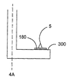
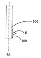
図3f、3gおよび3h、そして3iは、表面感知デバイスのスタイラス先端部5およびスタイラス面300の向きの4つの実施形態を示す。スタイラス先端部5は、スキッド180と直角を成し、スタイラスの面300に直角を成す。スタイラスの面300そしてひいてはスタイラス先端部5は、大きな孔の中へ動くとき、スタイラス先端部5を補助するように、図3fに示されているようにプローブの長手方向回転軸4Aに対してある角度で設けられることができる。図3gに示されているように、代わりに、スタイラスの面300は、被加工物の下部で検査するために、プローブの長手方向回転軸4Aに対して90度に設けられることができ、この場合、スタイラス先端部5はプローブの長手方向回転軸に平行にある。図3hに示されているような第3実施形態において、スタイラス面300は、プローブの長手方向回転軸4Aに平行に設けられることができる。この場合、スタイラス先端部5は、プローブの長手方向回転軸に対して直角を成し、小さな穴の内面へのアクセスのし易さを改善する。
FIGS. 3f, 3g and 3h, and 3i show four embodiments of the orientation of the
図3iに示されているような第4実施形態において、スタイラスは、90度でない角度に曲げられている。スタイラス先端部5は、プローブの長手方向軸4Aに対して横切る方向を向いている。被加工物の表面を感知するとき、スタイラス先端部5は、表面301に直角を成す方向に向かなければならない。有機的に統合されたプローブヘッドの動きおよび有機的に統合されたプローブヘッドの大きさの特定の制限のために、図3hに示されているようなまっすぐなスタイラスで、表された直角を成す感知配置を成し遂げることは可能ではない。図3iの曲げられたスタイラスは、スタイラス先端部に、プローブヘッドが表面を明確にするように位置づけられることを可能にし、したがって、スタイラス先端部5に、直角を成す位置からより多くの表面にアクセスすることを可能にする。
In a fourth embodiment as shown in FIG. 3i, the stylus is bent at a non-90 degree angle. The
図3lは、表面感知デバイスの、曲げられたスタイラスにおける被加工物の表面との感知関係を感知するための手段の概念図を示す。これは、同様の参照数字が同様のパーツを示す図3jに示されたスタイラスと様々に類似する。ハウジング185によって収容されたスタイラス501は、線500に沿ってプローブヘッドから取り外し可能である。レバー配置がスタイラスの曲げられた部分に設けられるのに対して、光路配置はスタイラスの真っ直ぐな部分に提供される。ミラーは、真っ直ぐなスタイラスのそれと同様に、ビームスプリッタに対して光ビームが戻るように、ある角度で2つの部分間の境界に設けられている。曲げられたスタイラスが同じ光学そしてひいては同じプローブを用いることができるこの手段は、真っ直ぐなスタイラスによって用いられるように備えられる。
FIG. 3l shows a conceptual diagram of the means for sensing the sensing relationship of the surface sensing device with the surface of the workpiece in the bent stylus. This is variously similar to the stylus shown in FIG. 3j where like reference numerals indicate like parts. The
一般に、スタイラス面300およびスタイラス先端部5は、被加工物の表面アクセスの便利さのために、プローブの長手方向回転軸に対して、任意の角度で設けられることができる。
In general, the
例えば、プローブ先端部が表面感知デバイスの長手方向軸に合わせられる場合、プローブは、表面感知デバイスの長手方向軸まわりに回転させられるとき、アクセスに関して利点を有さない。結果として、表面感知デバイスをその長手方向軸まわりに回転させることによって、被加工物の表面へのアクセスのし易さを増すという利点から利益を得るために、プローブ先端部は、前記長手方向軸を横切るあるいは長手方向軸からずれていなければならない。 For example, if the probe tip is aligned with the longitudinal axis of the surface sensing device, the probe has no advantage with respect to access when rotated about the longitudinal axis of the surface sensing device. As a result, in order to benefit from the advantage of increasing the accessibility of the surface of the workpiece by rotating the surface sensing device about its longitudinal axis, the probe tip may be Must be crossed or offset from the longitudinal axis.
Claims (34)
機械の可動アームに該支持体を取り付けるための取付手段と、
被加工物の表面を感知するための単一方向性プローブまたは表面仕上げプローブと、
第1回転軸まわりに前記取付手段に対して回転可能であって第1モーターによって動かされることができる第1部材と、第2回転軸まわりに前記第1部材に対して回転可能であって第2モーターによって動かされることができる第2部材とを有する前記支持体であって、前記第2回転軸は、前記第1回転軸を横切り、前記単一方向性プローブまたは表面仕上げプローブが、前記第2部材に、それとともに回転するために取り付けられることができる、前記支持体と
を備え、
回転手段が、第3回転軸まわりの前記支持体に対する前記単一方向性プローブまたは表面仕上げプローブの回転を可能にするために設けられている
ことを特徴とする被加工物の表面を測定するための装置。A support;
Attachment means for attaching the support to a movable arm of a machine;
A unidirectional probe or surface finish probe for sensing the surface of the workpiece;
A first member rotatable about the first rotation axis relative to the attachment means and movable by a first motor; and rotatable about the second rotation axis relative to the first member. A second member that can be moved by two motors, wherein the second axis of rotation crosses the first axis of rotation, and the unidirectional probe or surface finish probe is the first member. Comprising said support, which can be attached to two members for rotation therewith,
Rotating means is provided for measuring the surface of the workpiece, characterized in that it is provided to allow rotation of the unidirectional probe or surface finishing probe relative to the support about a third axis of rotation. Equipment.
該装置は、
支持体と、
機械の可動アームに該支持体を取り付けるための取付手段と、
被加工物の表面を感知するための単一方向性プローブまたは表面仕上げプローブと、
第1回転軸まわりに前記取付手段に対して回転可能であって第1モーターによって動かされることができる第1部材と、第2回転軸まわりに前記第1部材に対して回転可能であって第2モーターによって動かされることができる第2部材とを有する前記支持体であって、前記第2回転軸は、前記第1回転軸を横切り、前記単一方向性プローブまたは表面仕上げプローブが、前記第2部材に、それとともに回転するために取り付けられることができる、前記支持体と、
第3回転軸まわりの前記支持体に対する前記単一方向性プローブまたは表面仕上げプローブの回転を可能にするための回転手段と
を備え、
該方法は、前記支持体に対して前記前記単一方向性プローブまたは表面仕上げプローブを方向付けるように前記回転手段を作動させるステップを含むことを特徴とする方法。A method for using an apparatus for measuring the surface of a workpiece,
The device
A support;
Attachment means for attaching the support to a movable arm of a machine;
A unidirectional probe or surface finish probe for sensing the surface of the workpiece;
A first member rotatable about the first rotation axis relative to the attachment means and movable by a first motor; and rotatable about the second rotation axis relative to the first member. A second member that can be moved by two motors, wherein the second axis of rotation crosses the first axis of rotation, and the unidirectional probe or surface finish probe is the first member. Said support, which can be attached to two members for rotation therewith;
Rotating means for allowing rotation of the unidirectional probe or surface finish probe relative to the support about a third axis of rotation;
The method includes actuating the rotating means to direct the unidirectional probe or surface finish probe relative to the support.
前記被加工物の表面に関する情報を集めるステップと
をさらに含むことを特徴とする請求項13または14に記載の方法。Moving the surface finishing probe or unidirectional probe along the surface of the workpiece; and
15. The method according to claim 13 or 14, further comprising the step of collecting information relating to the surface of the workpiece.
支持体と、
機械の可動アームに該支持体を取り付けるための取付手段と、
被加工物の表面を感知するための表面感知デバイスと、
第1回転軸まわりに前記取付手段に対して回転可能であって第1モーターによって動かされる第1部材と、第2回転軸まわりに前記第1部材に対して回転可能であって第2モーターによって動かされる第2部材とを有する前記支持体であって、前記第2回転軸は、前記第1回転軸を横切り、前記表面感知デバイスが、前記第2部材に、それとともに回転するために取り付けられる、前記支持体と、
第3回転軸まわりの前記支持体に対する前記表面感知デバイスの回転を可能にするための回転手段であって、該第3回転軸は前記第1回転軸と合わさることが可能である、回転手段と
を備え、
前記第1回転軸および前記第3回転軸が合わせられるとき、前記表面感知デバイスに対する前記支持体の回転は、前記第1モーターによって作動可能であることを特徴とする装置。An apparatus for measuring the surface of a workpiece,
A support;
Attachment means for attaching the support to a movable arm of a machine;
A surface sensing device for sensing the surface of the workpiece;
A first member rotatable about the first rotation axis relative to the mounting means and moved by a first motor; and rotatable about the second rotation axis relative to the first member and driven by a second motor. Said support having a second member to be moved, wherein said second axis of rotation traverses said first axis of rotation and said surface sensing device is attached to said second member for rotation therewith. The support;
Rotating means for allowing rotation of the surface sensing device relative to the support about a third rotational axis, wherein the third rotational axis can be mated with the first rotational axis; With
The apparatus according to claim 1, wherein when the first rotation axis and the third rotation axis are aligned, rotation of the support relative to the surface sensing device is operable by the first motor.
該装置は、
支持体と、
機械の可動アームに該支持体を取り付けるための取付手段と、
被加工物の表面を感知するための表面感知デバイスと、
第1回転軸まわりに前記取付手段に対して回転可能であって第1モーターによって動かされる第1部材と、第2回転軸まわりに前記第1部材に対して回転可能であって第2モーターによって動かされる第2部材とを有する前記支持体であって、前記第2回転軸は、前記第1回転軸を横切り、前記表面感知デバイスが、前記第2部材に、それとともに回転するために取り付けられる、前記支持体と、
第3回転軸まわりの前記支持体に対する前記表面感知デバイスの回転を可能にするための回転手段であって、該第3回転軸は前記第1回転軸と合わさることが可能である、回転手段と
を備え、
該方法は、
前記第1回転軸および前記第3回転軸を合わせるステップと、そして、
前記表面感知デバイスに対する前記支持体の回転を生じさせるように、前記第1モーターを作動させるステップと
を含むことを特徴とする方法。A method for using an apparatus for measuring the surface of a workpiece,
The device
A support;
Attachment means for attaching the support to a movable arm of a machine;
A surface sensing device for sensing the surface of the workpiece;
A first member rotatable about the first rotation axis relative to the mounting means and moved by a first motor; and rotatable about the second rotation axis relative to the first member and driven by a second motor. Said support having a second member to be moved, wherein said second axis of rotation traverses said first axis of rotation and said surface sensing device is attached to said second member for rotation therewith. The support;
Rotating means for allowing rotation of the surface sensing device relative to the support about a third rotational axis, wherein the third rotational axis can be mated with the first rotational axis; With
The method
Aligning the first rotation axis and the third rotation axis; and
Activating the first motor to cause rotation of the support relative to the surface sensing device.
前記被加工物の表面に関する情報を集めるステップと
をさらに含むことを特徴とする請求項32に記載の方法。Moving the device along the surface of the workpiece; and
The method of claim 32, further comprising collecting information regarding a surface of the workpiece.
Applications Claiming Priority (5)
| Application Number | Priority Date | Filing Date | Title |
|---|---|---|---|
| GB0617344.7 | 2006-09-05 | ||
| GB0617344A GB0617344D0 (en) | 2006-09-05 | 2006-09-05 | Surface sensing device |
| GB0708572A GB0708572D0 (en) | 2007-05-03 | 2007-05-03 | Surface sensing device |
| GB0708572.3 | 2007-05-03 | ||
| PCT/GB2007/003295 WO2008029094A1 (en) | 2006-09-05 | 2007-08-31 | Surface sensing device |
Publications (3)
| Publication Number | Publication Date |
|---|---|
| JP2010502976A JP2010502976A (en) | 2010-01-28 |
| JP2010502976A5 JP2010502976A5 (en) | 2010-10-21 |
| JP5124579B2 true JP5124579B2 (en) | 2013-01-23 |
Family
ID=39156862
Family Applications (1)
| Application Number | Title | Priority Date | Filing Date |
|---|---|---|---|
| JP2009527191A Active JP5124579B2 (en) | 2006-09-05 | 2007-08-31 | Surface sensing device |
Country Status (7)
| Country | Link |
|---|---|
| US (1) | US8006399B2 (en) |
| EP (2) | EP2064514B2 (en) |
| JP (1) | JP5124579B2 (en) |
| CN (1) | CN102564306B (en) |
| AT (1) | ATE459856T1 (en) |
| DE (1) | DE602007005150D1 (en) |
| WO (1) | WO2008029094A1 (en) |
Families Citing this family (23)
| Publication number | Priority date | Publication date | Assignee | Title |
|---|---|---|---|---|
| GB0501690D0 (en) * | 2005-01-27 | 2005-03-02 | Renishaw Plc | Articulating device |
| SE533198C2 (en) * | 2008-02-14 | 2010-07-20 | Hexagon Metrology Ab | Measuring device with measuring head for control measurement of objects |
| GB0804114D0 (en) | 2008-03-05 | 2008-04-09 | Renishaw Plc | Surface sensing device |
| EP2381212B1 (en) * | 2010-04-26 | 2018-04-25 | Tesa Sa | Coordinate measuring system for rotationally symmetric workpieces |
| EP2384851B1 (en) * | 2010-05-03 | 2018-01-03 | Tesa Sa | Coordinate Measuring System with rotatory adapter |
| WO2012041274A1 (en) * | 2010-09-10 | 2012-04-05 | Carl Zeiss 3D Automation Gmbh | Tracer pin arrangement |
| JP6104557B2 (en) * | 2012-10-18 | 2017-03-29 | 株式会社ミツトヨ | Surface roughness measuring unit, 3D measuring device |
| US8881611B2 (en) | 2013-02-26 | 2014-11-11 | The Boeing Company | Automated inspection system |
| DE102015203369B4 (en) | 2015-02-25 | 2020-02-20 | Carl Zeiss Industrielle Messtechnik Gmbh | Method for determining the measurement conditions of a roughness sensor, method for measuring the roughness of a workpiece surface, computer program product and measuring device set up to carry out the method |
| DE102015209193A1 (en) | 2015-05-20 | 2016-11-24 | Carl Zeiss Industrielle Messtechnik Gmbh | Method for detecting dynamic vibrations of a roughness sensor, method for measuring the roughness of a workpiece surface, computer program product and measuring device configured to carry out the method. |
| JP6649013B2 (en) * | 2015-08-27 | 2020-02-19 | 株式会社ミツトヨ | Probe head rotation mechanism |
| EP3430350A1 (en) * | 2016-03-16 | 2019-01-23 | Hexagon Metrology, Inc | Probe clips for a coordinate measuring machine |
| US10663274B2 (en) | 2017-01-27 | 2020-05-26 | Faro Technologies, Inc | Articulated arm coordinate measuring machine |
| GB201702391D0 (en) | 2017-02-14 | 2017-03-29 | Renishaw Plc | Surface sensing device |
| WO2018150178A1 (en) | 2017-02-15 | 2018-08-23 | Renishaw Plc | Surface finish or surface roughness probe |
| DE102017103938A1 (en) | 2017-02-24 | 2018-08-30 | Carl Zeiss Industrielle Messtechnik Gmbh | Device for measuring the roughness of a workpiece surface |
| DE102017105814B3 (en) | 2017-03-17 | 2018-05-30 | Carl Zeiss Industrielle Messtechnik Gmbh | System for measuring the roughness of a surface of a workpiece |
| DE102017106425B4 (en) | 2017-03-24 | 2020-02-06 | Carl Zeiss Industrielle Messtechnik Gmbh | Device that can be moved by a coordinate measuring machine for positioning a measuring instrument with respect to a workpiece |
| JP6368986B1 (en) * | 2017-03-27 | 2018-08-08 | 株式会社東京精密 | Detector, surface texture measuring instrument, and roundness measuring instrument |
| DE102017003641B4 (en) | 2017-04-13 | 2019-10-17 | Carl Zeiss Industrielle Messtechnik Gmbh | Method for measuring coordinates or properties of a workpiece surface |
| DE102017108033A1 (en) | 2017-04-13 | 2018-10-18 | Carl Zeiss Industrielle Messtechnik Gmbh | Method for measuring coordinates or properties of a workpiece surface |
| GB201806830D0 (en) * | 2018-04-26 | 2018-06-13 | Renishaw Plc | Surface finish stylus |
| EP3827219B1 (en) | 2018-07-26 | 2023-08-30 | TESA Sàrl | Accessory for rotary probe support |
Family Cites Families (33)
| Publication number | Priority date | Publication date | Assignee | Title |
|---|---|---|---|---|
| US2867043A (en) † | 1952-10-16 | 1959-01-06 | Applic Electroniques Des Caout | Variable electric resistance semiconductor devices |
| US3727119A (en) | 1971-02-01 | 1973-04-10 | Information Dev Corp | Servo controlled automatic inspection apparatus |
| US3750295A (en) † | 1971-07-22 | 1973-08-07 | Werkzeugmasch Veb | Measuring machine |
| JPS5775503U (en) * | 1980-10-27 | 1982-05-10 | ||
| EP0312119A3 (en) | 1987-10-16 | 1989-05-31 | Nissan Motor Co., Ltd. | Three-dimensional measuring robot |
| DE3740070A1 (en) | 1987-11-26 | 1989-06-08 | Zeiss Carl Fa | TURN SLEWING DEVICE FOR TEST COOKING OF COORDINATE MEASURING DEVICES |
| GB8803847D0 (en) † | 1988-02-18 | 1988-03-16 | Renishaw Plc | Mounting for surface-sensing device |
| GB8908854D0 (en) † | 1989-04-19 | 1989-06-07 | Renishaw Plc | Method of and apparatus for scanning the surface of a workpiece |
| US5189806A (en) * | 1988-12-19 | 1993-03-02 | Renishaw Plc | Method of and apparatus for scanning the surface of a workpiece |
| EP0392660B1 (en) | 1989-04-14 | 1993-09-08 | Renishaw plc | Probe head |
| US5124524A (en) † | 1990-11-15 | 1992-06-23 | Laser Design Inc. | Laser alignment and control system |
| DE4039336C5 (en) * | 1990-12-10 | 2004-07-01 | Carl Zeiss | Process for fast workpiece temperature measurement on coordinate measuring machines |
| DE4308823C2 (en) | 1993-03-19 | 2002-11-07 | Zeiss Carl | Measuring probe for coordinate measuring machines |
| JPH0743102A (en) * | 1993-07-27 | 1995-02-10 | Etsuzo Fukuda | Probe positioning jig |
| GB9605278D0 (en) | 1996-03-13 | 1996-05-15 | Renishaw Plc | Opto-electronic scale reading apparatus |
| EP1189732B1 (en) † | 1999-06-26 | 2003-05-07 | KUKA Schweissanlagen GmbH | Method and device for calibrating robot measuring stations, manipulators and associated optical measuring devices |
| DE10006753A1 (en) * | 2000-02-15 | 2001-08-16 | Zeiss Carl | Rotary swivel device has correction unit which is included in each finite component to correct measurement error due to elastic deformation using mathematical model |
| DE50107776D1 (en) * | 2000-09-28 | 2005-11-24 | Zeiss Ind Messtechnik Gmbh | CALIBRATION OF A MEASURING SENSOR ON A COORDINATE MEASURING DEVICE WITH A BALL KNOWN THE CENTER |
| DE50115721D1 (en) | 2000-09-28 | 2011-01-05 | Zeiss Ind Messtechnik Gmbh | COORDINATE MEASURING DEVICE |
| DE10100352A1 (en) † | 2001-01-05 | 2002-07-11 | Zeiss Carl | Coordinate measuring machine with a splash guard for the probe of the coordinate measuring machine |
| JP2003014405A (en) * | 2001-07-04 | 2003-01-15 | Okuma Corp | Measuring stylus shared for front face and reverse face of workpiece |
| US6925722B2 (en) * | 2002-02-14 | 2005-08-09 | Faro Technologies, Inc. | Portable coordinate measurement machine with improved surface features |
| FR2837567B1 (en) † | 2002-03-19 | 2005-05-06 | Romain Granger | SENSOR FOR THREE-DIMENSIONAL COORDINATE MEASURING MACHINE |
| GB0207912D0 (en) * | 2002-04-05 | 2002-05-15 | Renishaw Plc | Kinematic coupling |
| GB0215152D0 (en) * | 2002-07-01 | 2002-08-07 | Renishaw Plc | Probe or stylus orientation |
| DE10260670B4 (en) † | 2002-12-23 | 2007-04-05 | Carl Zeiss Industrielle Messtechnik Gmbh | Device for optically scanning workpieces |
| GB2417090A (en) † | 2003-04-28 | 2006-02-15 | Stephen James Crampton | CMM arm with exoskeleton |
| US7257992B2 (en) | 2004-07-06 | 2007-08-21 | Cim Systems, Inc. | Surface finish tester apparatus and methods |
| EP1617172B1 (en) | 2004-07-16 | 2007-12-26 | Tesa SA | Steerable feeler head |
| JP4582446B2 (en) † | 2004-11-18 | 2010-11-17 | 株式会社東京精密 | measuring device |
| JP4568621B2 (en) | 2005-02-28 | 2010-10-27 | 株式会社ミツトヨ | Straightness correction method for surface texture measuring instrument and surface texture measuring instrument |
| GB0605796D0 (en) * | 2006-03-23 | 2006-05-03 | Renishaw Plc | Apparatus and method of measuring workpieces |
| EP1978328B1 (en) * | 2007-04-03 | 2015-02-18 | Hexagon Metrology AB | Oscillating scanning probe with constant contact force |
-
2007
- 2007-08-31 AT AT07804102T patent/ATE459856T1/en not_active IP Right Cessation
- 2007-08-31 EP EP07804102.7A patent/EP2064514B2/en active Active
- 2007-08-31 JP JP2009527191A patent/JP5124579B2/en active Active
- 2007-08-31 DE DE602007005150T patent/DE602007005150D1/en active Active
- 2007-08-31 WO PCT/GB2007/003295 patent/WO2008029094A1/en active Application Filing
- 2007-08-31 US US12/310,206 patent/US8006399B2/en active Active
- 2007-08-31 CN CN201110358458.0A patent/CN102564306B/en active Active
- 2007-08-31 EP EP10000459.7A patent/EP2207006B2/en active Active
Also Published As
| Publication number | Publication date |
|---|---|
| ATE459856T1 (en) | 2010-03-15 |
| DE602007005150D1 (en) | 2010-04-15 |
| US8006399B2 (en) | 2011-08-30 |
| EP2064514B2 (en) | 2014-08-06 |
| US20090255139A1 (en) | 2009-10-15 |
| EP2064514B1 (en) | 2010-03-03 |
| WO2008029094A1 (en) | 2008-03-13 |
| EP2207006B2 (en) | 2022-01-26 |
| CN102564306B (en) | 2014-09-24 |
| EP2207006A2 (en) | 2010-07-14 |
| EP2207006A3 (en) | 2010-11-03 |
| JP2010502976A (en) | 2010-01-28 |
| EP2207006B1 (en) | 2013-10-02 |
| EP2064514A1 (en) | 2009-06-03 |
| CN102564306A (en) | 2012-07-11 |
Similar Documents
| Publication | Publication Date | Title |
|---|---|---|
| JP5124579B2 (en) | Surface sensing device | |
| EP1875158B1 (en) | Surface sensing device with optical sensor | |
| US7676942B2 (en) | Multi-axis positioning and measuring system and method of using | |
| EP2259897B1 (en) | Surface sensing device | |
| JPH0789045B2 (en) | Three-dimensional displacement measuring instrument | |
| JP7531653B2 (en) | Method for calibrating a surface sensing device, corresponding calibration program for a control computer and corresponding calibration kit - Patents.com | |
| JP4570437B2 (en) | Surface roughness / contour shape measuring device | |
| JP2021094600A (en) | Machine tool and shape measurement method of workpiece machining part | |
| JP4067763B2 (en) | Photoelectric device for checking the size and / or shape of a part having a complex three-dimensional shape | |
| CN101512285B (en) | Surface sensing device | |
| WO2019155698A1 (en) | Surface shape measurement device | |
| JPS63289410A (en) | Three-dimensional measuring instrument | |
| RU2084326C1 (en) | Machining device | |
| JP2019138898A (en) | Surface shape measurement device |
Legal Events
| Date | Code | Title | Description |
|---|---|---|---|
| A521 | Request for written amendment filed |
Free format text: JAPANESE INTERMEDIATE CODE: A523 Effective date: 20100831 |
|
| A621 | Written request for application examination |
Free format text: JAPANESE INTERMEDIATE CODE: A621 Effective date: 20100831 |
|
| A977 | Report on retrieval |
Free format text: JAPANESE INTERMEDIATE CODE: A971007 Effective date: 20120822 |
|
| TRDD | Decision of grant or rejection written | ||
| A01 | Written decision to grant a patent or to grant a registration (utility model) |
Free format text: JAPANESE INTERMEDIATE CODE: A01 Effective date: 20120831 |
|
| A01 | Written decision to grant a patent or to grant a registration (utility model) |
Free format text: JAPANESE INTERMEDIATE CODE: A01 |
|
| A601 | Written request for extension of time |
Free format text: JAPANESE INTERMEDIATE CODE: A601 Effective date: 20121001 |
|
| A602 | Written permission of extension of time |
Free format text: JAPANESE INTERMEDIATE CODE: A602 Effective date: 20121010 |
|
| A61 | First payment of annual fees (during grant procedure) |
Free format text: JAPANESE INTERMEDIATE CODE: A61 Effective date: 20121029 |
|
| FPAY | Renewal fee payment (event date is renewal date of database) |
Free format text: PAYMENT UNTIL: 20151102 Year of fee payment: 3 |
|
| R150 | Certificate of patent or registration of utility model |
Free format text: JAPANESE INTERMEDIATE CODE: R150 Ref document number: 5124579 Country of ref document: JP Free format text: JAPANESE INTERMEDIATE CODE: R150 |
|
| R250 | Receipt of annual fees |
Free format text: JAPANESE INTERMEDIATE CODE: R250 |
|
| R250 | Receipt of annual fees |
Free format text: JAPANESE INTERMEDIATE CODE: R250 |
|
| R250 | Receipt of annual fees |
Free format text: JAPANESE INTERMEDIATE CODE: R250 |
|
| R250 | Receipt of annual fees |
Free format text: JAPANESE INTERMEDIATE CODE: R250 |
|
| R250 | Receipt of annual fees |
Free format text: JAPANESE INTERMEDIATE CODE: R250 |
|
| R250 | Receipt of annual fees |
Free format text: JAPANESE INTERMEDIATE CODE: R250 |
|
| R250 | Receipt of annual fees |
Free format text: JAPANESE INTERMEDIATE CODE: R250 |
|
| R250 | Receipt of annual fees |
Free format text: JAPANESE INTERMEDIATE CODE: R250 |
|
| R250 | Receipt of annual fees |
Free format text: JAPANESE INTERMEDIATE CODE: R250 |