JP5123100B2 - microscope - Google Patents
microscope Download PDFInfo
- Publication number
- JP5123100B2 JP5123100B2 JP2008204581A JP2008204581A JP5123100B2 JP 5123100 B2 JP5123100 B2 JP 5123100B2 JP 2008204581 A JP2008204581 A JP 2008204581A JP 2008204581 A JP2008204581 A JP 2008204581A JP 5123100 B2 JP5123100 B2 JP 5123100B2
- Authority
- JP
- Japan
- Prior art keywords
- microscope
- column
- support column
- mirror
- support
- Prior art date
- Legal status (The legal status is an assumption and is not a legal conclusion. Google has not performed a legal analysis and makes no representation as to the accuracy of the status listed.)
- Expired - Fee Related
Links
Images


Description
本発明は、生物、医学、半導体などの分野において使用される正立型の顕微鏡に関するものである。 The present invention relates to an upright microscope used in the fields of biology, medicine, semiconductors, and the like.
従来、図7に示すような正立型の顕微鏡が知られている。
図7に示すように、この顕微鏡は、ベース部1001と略逆くの字状の片持ち式アーム部1002とを備える。アーム部1002の自由端側の上方には、標本1012を観察するための鏡筒1003、双眼部1004及び接眼レンズ1005が配置される。一方、アーム部1002の自由端側の下方にはレボルバー1006が、アーム部1002の湾曲部近傍にはステージ1008が配置される。対物レンズ1007は、レボルバー1006に着脱可能に固定され、コンデンサ1010は、ステージ1008下部に取り付けられている。
Conventionally, an upright microscope as shown in FIG. 7 is known.
As shown in FIG. 7, this microscope includes a
ステージ1008の下方には、ステージ1008を水平方向に移動操作するためのステージハンドル1009が配置されてある。また、アーム部1002の下部にはステージ1008を上下動操作するための焦準ハンドル1011が配置されてある。ステージハンドル1009及び焦準ハンドル1011を操作することで、ステージ1008上に載置された標本1012にその焦点位置を合わせることができる。
A
ベース部1001内部には不図示のランプが配置されており、ランプからの光がコンデンサ1010にて集光され、標本1012に照射されるようになっている。標本1012の像は、対物レンズ1007、鏡筒1003、双眼部1004及び接眼レンズ1005を介して観察者の目に届く。このようにすることで標本を観察することができる。
A lamp (not shown) is disposed inside the
一般に、こうした顕微鏡を用いて標本を長時間観察する際には、顕微鏡フレームにランプ熱による熱たわみが生じ焦点ズレが起こる可能性がある。こうした熱たわみの発生を抑制可能な顕微鏡として、フレーム側面に着脱可能な補助支柱を設けることによってフレームの剛性を高めた顕微鏡が知られている(例えば、特許文献1参照)。 In general, when a specimen is observed for a long time using such a microscope, there is a possibility that the microscope frame is subject to thermal deflection due to lamp heat and a focus shift occurs. As a microscope that can suppress the occurrence of such thermal deflection, a microscope is known in which the rigidity of the frame is increased by providing an auxiliary column that can be attached and detached on the side of the frame (see, for example, Patent Document 1).
ところで、上記の従来の図7の顕微鏡では、ベース部と鏡筒を支えるアーム部とが一体となっているため、ステージの操作ハンドル、焦準ハンドル、調光ボリュームなどの操作部は、観察者に対して常に同じ向きになっている。また左右の利き手に合わせるため、焦準ハンドルを両側に備える必要がある。 By the way, in the conventional microscope shown in FIG. 7, since the base portion and the arm portion supporting the lens barrel are integrated, the operation portions such as the operation handle of the stage, the focusing handle, and the dimming volume are used by the observer. Is always in the same direction. In addition, it is necessary to provide focusing handles on both sides in order to match the right and left handedness.
また、上記の従来の特許文献1の顕微鏡では、補助支柱の取り付け位置が顕微鏡本体の両側面に固定されているため、補助支柱の取り付け位置を観察者の利き手に合わせて選択できないようになっている。 Further, in the above-described conventional microscope of Patent Document 1, the attachment position of the auxiliary column is fixed to both side surfaces of the microscope main body, so that the attachment position of the auxiliary column cannot be selected according to the dominant hand of the observer. Yes.
本発明は、上記実情に鑑みてなされたものであり、ベース部と鏡体部とを連結する支柱を、正立状態を保ちながら容易に着脱することができる顕微鏡を提供することを目的とする。 The present invention has been made in view of the above circumstances, and an object of the present invention is to provide a microscope capable of easily attaching and detaching a support column that connects a base portion and a mirror portion while maintaining an upright state. .
上記の目的を達成するために、本発明に係る顕微鏡は、ベース部と鏡体部とこれらを連結保持する支柱とを備え、前記ベース部には、光軸中心に回転自在なステージが載置され、前記鏡体部には、焦準機構を有するレボルバーと、光軸中心に回転自在な鏡筒とが設けられた正立型の顕微鏡において、前記支柱は、正立状態を維持した状態で着脱可能に構成されることを特徴とする。 In order to achieve the above object, a microscope according to the present invention includes a base portion, a mirror body portion, and a support column that connects and holds them, and a stage that is rotatable about the optical axis is placed on the base portion. In the upright microscope provided with a revolver having a focusing mechanism and a lens barrel that is rotatable about the optical axis in the mirror part, the support column is in an upright state. It is configured to be detachable.
また、本発明に係る顕微鏡は、上述した発明において、前記ベース部と前記鏡体部とに、前記支柱を上下方向に位置決めして固定する固定つまみを備えたことを特徴とする。 Moreover, the microscope according to the present invention is characterized in that, in the above-described invention, a fixing knob for positioning and fixing the support column in the vertical direction is provided on the base portion and the mirror body portion.
また、本発明に係る顕微鏡は、上述した発明において、前記支柱の下端に上下方向に複数の段差を設け、前記ベース部の溝部に突起部を設け、前記段差が前記突起部に嵌合可能であることを特徴とする。 In the microscope according to the present invention, in the above-described invention, a plurality of steps in the vertical direction are provided at the lower end of the support column, a protrusion is provided in the groove of the base, and the step can be fitted to the protrusion. It is characterized by being.
また、本発明に係る顕微鏡は、上述した発明において、前記支柱は、前記鏡体部に4本設置され、前記支柱は、シャフトを上下方向に摺動可能に内装する円筒部材によって構成され、前記支柱下部に調整ねじを設け、前記支柱下端に弾性部材を備えたことを特徴とする。 Further, the microscope according to the present invention is the above-described invention, wherein the four support columns are installed on the mirror body, and the support columns are configured by a cylindrical member that slidably mounts a shaft in the vertical direction, An adjustment screw is provided at the bottom of the support, and an elastic member is provided at the lower end of the support.
また、本発明に係る顕微鏡は、上述した発明において、前記鏡体部と前記ベース部のそれぞれの側面に複数のねじ穴が設けられ、前記支柱は、前記ねじ穴にボルトにより選択的に固定可能であることを特徴とする。 Further, in the microscope according to the present invention, in the above-described invention, a plurality of screw holes are provided on each side surface of the mirror body part and the base part, and the support column can be selectively fixed to the screw hole with a bolt. It is characterized by being.
また、本発明に係る顕微鏡は、上述した発明において、前記鏡体部と前記ベース部はそれぞれ磁性部材を備え、前記支柱は前記磁性部材に対して磁力によって着脱可能なマグネット部を備えたことを特徴とする。 In the microscope according to the present invention, in the above-described invention, the mirror part and the base part each include a magnetic member, and the support column includes a magnet part that can be attached to and detached from the magnetic member by a magnetic force. Features.
本発明によれば、ベース部と鏡体部とこれらを連結保持する支柱とを備え、前記ベース部には、光軸中心に回転自在なステージが載置され、前記鏡体部には、焦準機構を有するレボルバーと、光軸中心に回転自在な鏡筒とが設けられた正立型の顕微鏡において、前記支柱は、正立状態を維持した状態で着脱可能に構成されるので、顕微鏡を正立状態に維持したままで支柱を容易に着脱できる。このため、観察者の使用状態や好みに応じて所望の位置の支柱を着脱することによって、顕微鏡の各種操作部が観察者の所望の向きに配置された状態を作り出すことができる。このようにすることで、観察者は顕微鏡の各種操作部を前後左右、好きな向きに配置することができる。また、支柱を必要に応じて追加することで、顕微鏡の剛性を一時的に高めた状態を作り出すこともできる。 According to the present invention, a base portion, a mirror body portion, and a support column for connecting and holding them are provided, and a stage that is rotatable about the optical axis is placed on the base portion. In an upright microscope provided with a revolver having a quasi-mechanism and a lens barrel that is rotatable about the optical axis, the column is configured to be detachable while maintaining an upright state. The column can be easily attached and detached while maintaining the upright state. For this reason, it is possible to create a state in which various operation units of the microscope are arranged in a desired direction of the observer by attaching and detaching the support column at a desired position according to the use state and preference of the observer. By doing in this way, the observer can arrange | position the various operation parts of a microscope in front and rear, right and left, a favorite direction. Moreover, the state which raised the rigidity of the microscope temporarily can also be produced by adding a support | pillar as needed.
また、本発明の他の顕微鏡によれば、前記ベース部と前記鏡体部とに、前記支柱を上下方向に位置決めして固定する固定つまみを備えたので、請求項1の作用及び効果に加え、固定つまみをベース部と鏡体部に備えることで、工具を使わずに支柱を固定することができる。 According to another microscope of the present invention, since the base portion and the mirror portion are provided with the fixing knob for positioning and fixing the support column in the vertical direction, in addition to the operations and effects of claim 1 By providing the fixing knobs on the base part and the mirror part, it is possible to fix the column without using a tool.
また、本発明の他の顕微鏡によれば、前記支柱の下端に上下方向に複数の段差を設け、前記ベース部の溝部に突起部を設け、前記段差が前記突起部に嵌合可能であるので、請求項1又は2の作用及び効果に加え、上下方向の複数の段差から任意の段差を、ベース部の突起部に対して観察者が選択的に嵌合することにより、支柱の高さを変えることができる。こうすることによって、ベース部からの鏡体の位置を高くすることができ、厚みのある標本も観察することができる。 Further, according to another microscope of the present invention, a plurality of steps in the vertical direction are provided at the lower end of the column, a protrusion is provided in the groove of the base, and the step can be fitted to the protrusion. In addition to the functions and effects of claim 1 or 2, the observer can selectively fit any step from a plurality of steps in the vertical direction to the protrusion of the base portion, thereby increasing the height of the column. Can be changed. By doing so, the position of the mirror body from the base portion can be increased, and a thick specimen can also be observed.
また、本発明の他の顕微鏡によれば、前記支柱は、前記鏡体部に4本設置され、前記支柱は、シャフトを上下方向に摺動可能に内装する円筒部材によって構成され、前記支柱下部に調整ねじを設け、前記支柱下端に弾性部材を備えたので、鏡体部を4本の支柱によって正立状態で保持することができる。このため、ベース部を用いずにベース部やステージに載せられない大型の観察対象物も観察することができる。 According to another microscope of the present invention, four of the support columns are installed in the mirror body, and the support columns are configured by cylindrical members that are slidably mounted in the vertical direction, Since the adjusting screw is provided on the lower end of the column and the elastic member is provided at the lower end of the column, the mirror body can be held upright by the four columns. For this reason, it is possible to observe a large observation object that cannot be placed on the base part or the stage without using the base part.
また、本発明の他の顕微鏡によれば、前記鏡体部と前記ベース部のそれぞれの側面に複数のねじ穴が設けられ、前記支柱は、前記ねじ穴にボルトにより選択的に固定可能であるので、請求項1の作用及び効果に加え、4本以上の支柱を着脱することができ、高剛性の顕微鏡を提供することができる。 According to another microscope of the present invention, a plurality of screw holes are provided on each side surface of the mirror part and the base part, and the support column can be selectively fixed to the screw hole with a bolt. Therefore, in addition to the operation and effect of the first aspect, four or more columns can be attached and detached, and a high-rigidity microscope can be provided.
また、本発明の他の顕微鏡によれば、前記鏡体部と前記ベース部はそれぞれ磁性部材を備え、前記支柱は前記磁性部材に対して磁力によって着脱可能なマグネット部を備えたので、請求項1の作用及び効果に加え、ボルト等を使わずに容易に支柱を着脱固定することができる。このため、支柱をねじ穴の位置に左右されることなく、好きな位置に配置できる。 According to another microscope of the present invention, each of the mirror part and the base part includes a magnetic member, and the support column includes a magnet part that can be attached to and detached from the magnetic member by a magnetic force. In addition to the operation and effect of 1, the support can be easily attached and detached without using bolts or the like. For this reason, a support | pillar can be arrange | positioned in a favorite position, without being influenced by the position of a screw hole.
以下に添付図面を参照しながら、本発明に係る顕微鏡の好適な実施の形態(実施の形態1〜4と変形例1、2)を詳細に説明する。 Exemplary embodiments of the microscope according to the present invention (Embodiments 1 to 4 and Modifications 1 and 2) will be described below in detail with reference to the accompanying drawings.
(実施の形態1)
本発明の実施の形態1の顕微鏡について、図1a〜図1hを用いて説明する。図1aは、実施の形態1の顕微鏡の正面図であり、図1bは、実施の形態1の顕微鏡の側面図である。
(Embodiment 1)
A microscope according to Embodiment 1 of the present invention will be described with reference to FIGS. FIG. 1a is a front view of the microscope according to the first embodiment, and FIG. 1b is a side view of the microscope according to the first embodiment.
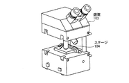
図1a、図1bに示すように、本実施の形態1の顕微鏡は、鏡体部101とベース部102とこれらを連結保持する支柱106とからなる正立顕微鏡である。ベース部102には、水平方向に標本131を移動させるステージ104が載置されており、ステージ104は、図示しない丸アリにより回転可能にベース部102に嵌合固定されている。ベース部102には、標本131に光を導くための図示しないランプ光源及びコンデンサが内蔵されている。
As shown in FIGS. 1 a and 1 b, the microscope according to the first embodiment is an upright microscope including a
鏡体部101は、対物レンズ105、レボルバー109、鏡筒103を備える。鏡筒103は、ステージ104と同様に図示しない丸アリにより鏡体部101に嵌合固定されている。
The
図1bに示すように、支柱106は、上下両端の固定つまみ107でベース部102と鏡体部101とに着脱可能に取り付けられる。ベース部102と鏡体部101の支柱106両端の各取り付け部には、鏡体側凹部101a、ベース部凹部102aがそれぞれ設けてある。
As shown in FIG. 1 b, the
次に、固定つまみ107と支柱106の端部の構成について、鏡体部101と支柱106の取り付け部を例にとり、図1cの断面図を用いて説明する。
Next, the configuration of the end portions of the
支柱106の上端部には、水平方向に開口するテーパ状の支柱固定穴106aが設けられている。一方、水平方向の回転軸心を有する円柱状の固定つまみ107の先端にはテーパ形状部材107aが同軸上に設けられている。鏡体部101には支柱固定穴106aへ固定つまみ107を挿通可能な嵌合穴101bが水平方向に開口して設けられている。
A tapered
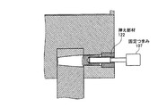
テーパ形状部材107aは、固定穴106aに対して上方向に偏心した状態で嵌合する一方、鏡体部101側の嵌合穴101bとは摺動可能に嵌合している。嵌合穴101bには、圧縮ばね121が内装されており、圧縮ばね121の抜け落ちを防止するため環状の押え部材122が嵌合穴101bの入口で鏡体部101に固定されている。また、固定つまみ107には軸上におねじ107bが、押え部材122の内径部にはめねじ122aが施されている。なお、ベース部102側の支柱106の端部及び固定つまみ107も同様の構成となっている。
The taper-shaped
上記の実施の形態1の構成の動作及び作用について説明する。
支柱106の着脱は、図1dに示す矢印方向のように顕微鏡の側面から行う。支柱106を取り外す際は、図1eに示すように固定つまみ107を矢印方向に引っ張りながら、固定つまみ107を左回転させる。そうすると圧縮ばね121が圧縮され、押え部材122のめねじ122aと固定つまみ107のおねじ107bとがねじ締結され、固定つまみ107が支柱106から抜けた状態で、そのまま支柱106を図1dのように取り外すことが可能である。
The operation and action of the configuration of the first embodiment will be described.
The
逆に、支柱106を固定する際は、取り外しと逆の手順で行う。支柱106を凹部101a等に取り付け、固定つまみ107を右回転することにより、圧縮ばね121が開放されて、図1cの状態になる。固定つまみ107先端のテーパ形状部材107aが支柱固定穴106aの中心に対して上方向にずれているため、支柱106全体を上方向に当てつくことができる。なお、支柱106を固定する際の手順は、ベース部102と固定つまみ107についてもこれと同様である。
On the contrary, when fixing the
以上の本実施の形態1の構成によれば、顕微鏡の正立状態を維持しながら、支柱106を着脱することができる。また、2本の支柱106の取り付け箇所を、予め準備した四隅4箇所の中から選択することによって、所望の取り付け箇所に支柱106を取り付けることができる。
According to the configuration of the first embodiment described above, the
また、本実施の形態1の構成によれば、支柱106による支持を2本から3本、4本に追加することができ、長時間観察などを行う際に顕微鏡の剛性を上げることも可能である。さらに、鏡筒103、ステージ104がそれぞれ回転可能であるため、図1fに示すように、観察者の使用状態にあわせて鏡体部101に設けられる焦準ハンドル108と、ベース部102に設けられる調光ボリューム110及び電源スイッチ111との向きを合わせることや、図1gに示すように、鏡筒103に対してステージ104を縦置きにすることもできる。また、図1hに示すように、固定つまみ107の固定は、圧縮ばね121を用いずに、固定つまみ107と押え部材122によるネジの締結によって構成してもよい。
Further, according to the configuration of the first embodiment, the support by the
(実施の形態2)
次に、本発明の実施の形態2の顕微鏡について、図2a〜図2dを用いて説明する。
(Embodiment 2)
Next, the microscope according to the second embodiment of the present invention will be described with reference to FIGS.
図2aに示すように、本実施の形態2の顕微鏡の支柱201は円柱状をなし、ベース部202側の外周の一部には柱軸方向視で複数のDカット形状の段差201a〜201cが設けてある。また、柱軸方向視で段差201a〜201cとそれぞれ直交した位置の外周には、固定つまみ107が挿入される固定穴201d〜201fが設けてある。一方、図2bに示すように、ベース部202の支柱201取り付け箇所の凹部には、上面視でD字形状の突起部202aが設けてある。
As shown in FIG. 2a, the column 201 of the microscope according to the second embodiment has a columnar shape, and a plurality of D-cut steps 201a to 201c are formed in a part of the outer periphery on the side of the
上記の実施の形態2の構成の動作及び作用について説明する。
図2cに示すように、支柱201がベース部202に取り付けられた状態では、支柱201の段差201bがベース部202側の突起部202aに噛み合わされることにより、支柱201の上下方向の位置が決まる。図2cでは、突起部202aが支柱201の段差201bに噛み合わされているが、段差201a、段差201cに突起部202aを噛み合わせることもできる。また支柱201を固定する固定つまみ107は、図2dに示すように配置されており、段差201a〜201cの位置に合わせて、支柱201用の固定穴201d〜201fに固定つまみ107が挿入される。
The operation and action of the configuration of the second embodiment will be described.
As shown in FIG. 2c, in the state where the support column 201 is attached to the
以上の本実施の形態2の構成によれば、ベース部202の突起部202aと噛み合わせる段差201a〜201cの位置を選択できることにより、支柱201の高さを調節でき、厚みのある標本を観察することができる。
According to the configuration of the second embodiment described above, the position of the steps 201a to 201c to be engaged with the protruding
(実施の形態3)
次に、本発明の実施の形態3の顕微鏡について、図3a〜図3bを用いて説明する。
(Embodiment 3)
Next, a microscope according to Embodiment 3 of the present invention will be described with reference to FIGS. 3a to 3b.
図3aに示すように、本実施の形態3の顕微鏡は、支柱301下端にゴム足302を供える。支柱301とベース部300の当付固定は、ベース部300に設けられた段差による当付面300aにて行われている。また、図3bに示すように、鏡体部320には落射光学系が内蔵されている。鏡体320内部に光源303、ハーフミラー304を備え、鏡筒321内部には、結像レンズ323、第1ミラー305、第2ミラー306を備えている。
As shown in FIG. 3 a, the microscope according to the third embodiment provides a
上記の実施の形態3の構成の動作及び作用について説明する。
図3bに示すように、鏡体部320に内蔵されている光源303から照射された光がハーフミラー304に折り返され、対物レンズ322を通して標本(不図示)に照射される。標本から反射された光は、対物レンズ322により拡大され、結像レンズ323により結像されながら、第1ミラー305、第2ミラー306にて折り返されて、鏡筒321にて標本(不図示)を観察することができる。
The operation and action of the configuration of the third embodiment will be described.
As shown in FIG. 3 b, the light emitted from the light source 303 built in the
なお、ベース部300を取り外し、図3bに示すように、鏡体部320に支柱301を4本固定することにより、鏡体部320を正立状態で維持することができる。
In addition, by removing the
以上の本実施の形態3の構成によれば、ベース部及びステージがない鏡体部のみで、落射観察を行うことができる。ベース部に載せられないシリコンウエハ、鉱石などの大型の対象物を観察することも可能となる。 According to the above-described configuration of the third embodiment, it is possible to perform epi-illumination observation only with the base part and the mirror part without the stage. It is also possible to observe large objects such as silicon wafers and ores that cannot be placed on the base.
(実施の形態4)
次に、本発明の実施の形態4の顕微鏡について、図4a〜図4bを用いて説明する。
(Embodiment 4)
Next, a microscope according to Embodiment 4 of the present invention will be described with reference to FIGS. 4a to 4b.
図4aに示すように、本実施の形態4の顕微鏡は、鏡体部402及びベース部403の支柱401を取り付ける箇所に複数のねじ穴402a、403aがそれぞれ施されてある。一方、支柱401の両端には固定ボルト404が取り付くように、図示しない取り付け穴が施されている。
As shown in FIG. 4a, in the microscope according to the fourth embodiment, a plurality of
図4bに示すように、支柱401の両端にはDカットが施されている。支柱401固定時は、鏡体部402、ベース部403の水平方向と上下方向の位置決めは、支柱401の横方向当付面401a、縦方向当付面401b部分にて行われる。
As shown in FIG. 4b, both ends of the
上記の実施の形態4の構成の動作及び作用について説明する。
支柱401の取付穴を鏡体部402、ベース部403のねじ穴402a、403aにあわせながら、固定ボルト404で固定することにより、支柱401を取り付けることができる。また固定ボルト404を外すことで、鏡体部402、ベース部403から支柱401を容易に取り外すことが可能である。
The operation and action of the configuration of the fourth embodiment will be described.
The
以上の本実施の形態4の構成によれば、ベース部及び鏡体部への支柱の装着を、予めベース部及び鏡体部に設けた複数のねじ穴にボルトで選択的に固定することにより、4本以上の支柱を固定できるため、顕微鏡の剛性をさらに高めることができる。 According to the configuration of the fourth embodiment described above, the mounting of the column to the base part and the mirror body part is selectively fixed with bolts to a plurality of screw holes provided in the base part and the mirror body part in advance. Since four or more struts can be fixed, the rigidity of the microscope can be further increased.
(変形例1)
次に、実施の形態3を変形した変形例1を図5a、図5bを用いて説明する。
図5aに示すように、鏡体部520に4本の支柱500が取り付けられている。支柱500の先端には、円筒支柱502が設置され、円筒支柱502の先端には、調整ねじ504がねじ止め固定され、ゴム足503が備えられている。図5bに示すように、円筒支柱502には、高さ調整つまみ501がねじ止め固定されている。
(Modification 1)
Next, a first modification obtained by modifying the third embodiment will be described with reference to FIGS. 5A and 5B.
As shown in FIG. 5 a, four
上記の変形例1の動作及び作用について説明する。
高さ調整つまみ501を緩めることにより、支柱500と円筒支柱502の上下方向の位置関係を変える。高さ調整つまみ501を締めることにより、支柱500と円筒支柱502の位置が固定される。さらに細かい高さ調整を行う場合には、調整ねじ504を回転させて微調整を行う。
The operation and action of Modification 1 will be described.
By loosening the
以上の本変形例1の構成によれば、支柱500と円筒支柱502の高さを変えることにより、鏡体520の高さを変えることができ、厚い標本、薄い標本の両方に対応することができる。また4本の支柱の高さを各々好きな位置に変えることができるため、平面でない場所に顕微鏡を置いても観察を行うことができる。
According to the configuration of the first modification described above, the height of the mirror body 520 can be changed by changing the heights of the
(変形例2)
次に、実施の形態4を変形した変形例2を、図6a〜図6cを用いて説明する。
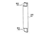
図6aに示すように、支柱601の両端にDカットを施し、マグネット部としての磁石602を水平面と垂直面に設置する。また、図6bに示すように、鏡体部603、ベース部604に前後左右面に磁性部材603a、604aを備える。図6cに示すように、支柱601に設けられた磁石602部分にて、鏡体部603、ベース部604の磁性部材603a、604aと磁力により固定されている。
(Modification 2)
Next, a second modification obtained by modifying the fourth embodiment will be described with reference to FIGS. 6a to 6c.
As shown in FIG. 6a, both ends of the support column 601 are D-cut, and
上記の変形例2の動作及び作用について説明する。
取り外しの際は、支柱601を回転させながら、横にスライドさせて、磁性部材603a、604aから磁石602部分が外れるように取り外す。
The operation and action of Modification 2 will be described.
At the time of removal, the column 601 is slid sideways while rotating so that the
以上の本変形例2の構成によれば、上記の実施の形態4の作用及び効果に加え、ボルトを使わずに支柱を固定できるため、ネジ穴の位置に左右されず支柱の位置を水平方向の好きな位置に配置でき、さらに支柱の着脱を容易に行うことができる。 According to the configuration of the second modification described above, in addition to the operation and effect of the above-described fourth embodiment, since the support can be fixed without using bolts, the position of the support is not affected by the position of the screw hole. It can be placed at any desired position, and the column can be easily attached and detached.
101,320,402,520,603 鏡体部
101a 鏡体側凹部
101b 嵌合穴
102,202,300,403,604 ベース部
102a ベース部凹部
103,321 鏡筒
104 ステージ
105,322 対物レンズ
106,201,301,401,500,601 支柱
106a 支柱固定穴
107 固定つまみ
107a テーパ形状部材
107b おねじ
108 焦準ハンドル
109 レボルバー
110 調光ボリューム
111 電源スイッチ
121 圧縮ばね
122 押え部材
122a 押え部材めねじ
131 標本
201a,201b、201c 段差
201d,201e,201f 固定穴
202a ベース部突起
300a 当付面
302,503 ゴム足
303 光源
304 ハーフミラー
305 第1ミラー
306 第2ミラー
323 結像レンズ
401a 横方向当付面
401b 縦方向当付面
402a,403a 支柱固定ねじ穴
404 固定ボルト
501 高さ調整つまみ
502 円筒支柱
504 調整ねじ
602 磁石
603a,604a 磁性部材
101, 320, 402, 520, 603 Mirror body portion 101a Mirror body
Claims (6)
前記ベース部と分離され、対物レンズとレボルバーと鏡筒を有する鏡体部と、
前記ベース部の凹部に固定可能であって、前記ベース部と前記鏡体部を連結保持する複数の支柱とを備え、
前記支柱は、正立状態を維持した状態で着脱可能に構成されることを特徴とする顕微鏡。 A stage on which a stage for moving the specimen is mounted and having a recess;
A body part separated from the base part and having an objective lens, a revolver, and a lens barrel;
A securable in the recess of the base portion, and a plurality of struts consolidated hold said base portion said mirror section,
The microscope, wherein the support column is configured to be detachable while maintaining an upright state.
Priority Applications (1)
| Application Number | Priority Date | Filing Date | Title |
|---|---|---|---|
| JP2008204581A JP5123100B2 (en) | 2008-08-07 | 2008-08-07 | microscope |
Applications Claiming Priority (1)
| Application Number | Priority Date | Filing Date | Title |
|---|---|---|---|
| JP2008204581A JP5123100B2 (en) | 2008-08-07 | 2008-08-07 | microscope |
Publications (3)
| Publication Number | Publication Date |
|---|---|
| JP2010039379A JP2010039379A (en) | 2010-02-18 |
| JP2010039379A5 JP2010039379A5 (en) | 2011-08-25 |
| JP5123100B2 true JP5123100B2 (en) | 2013-01-16 |
Family
ID=42011971
Family Applications (1)
| Application Number | Title | Priority Date | Filing Date |
|---|---|---|---|
| JP2008204581A Expired - Fee Related JP5123100B2 (en) | 2008-08-07 | 2008-08-07 | microscope |
Country Status (1)
| Country | Link |
|---|---|
| JP (1) | JP5123100B2 (en) |
Families Citing this family (4)
| Publication number | Priority date | Publication date | Assignee | Title |
|---|---|---|---|---|
| CN102436062B (en) * | 2010-09-29 | 2015-08-05 | 鸿富锦精密工业(深圳)有限公司 | Microscopie unit |
| CN103454747A (en) * | 2013-08-31 | 2013-12-18 | 昆山建金工业设计有限公司 | Light machine device for microorganisms |
| CN104076500A (en) * | 2014-06-27 | 2014-10-01 | 苏州科德溯源仪器有限公司 | Rapid focusing device for microscope |
| CN105277487A (en) * | 2015-09-29 | 2016-01-27 | 张义勇 | Metallographic analysis method |
Family Cites Families (1)
| Publication number | Priority date | Publication date | Assignee | Title |
|---|---|---|---|---|
| JP2002162570A (en) * | 2000-11-24 | 2002-06-07 | Nikon Corp | Erect microscope |
-
2008
- 2008-08-07 JP JP2008204581A patent/JP5123100B2/en not_active Expired - Fee Related
Also Published As
| Publication number | Publication date |
|---|---|
| JP2010039379A (en) | 2010-02-18 |
Similar Documents
| Publication | Publication Date | Title |
|---|---|---|
| JP5123100B2 (en) | microscope | |
| JP3537194B2 (en) | Light microscope | |
| EP1582904A1 (en) | System microscope | |
| JP3362892B2 (en) | microscope | |
| JP4806526B2 (en) | Replaceable microscope stage drive assembly | |
| JP2006091723A (en) | Inverted microscope | |
| JP2005157382A (en) | Device for controlling adjustment of ergonomically arranged observation sample | |
| JP2011242815A (en) | Microscope system, and observation method | |
| JP6637350B2 (en) | Upright microscope | |
| US7075715B2 (en) | Mouth switch arrangement and microscope with mouth switch arrangement | |
| US20040051979A1 (en) | Magnetic optical element holder and microscope assembly including same | |
| JP6978592B2 (en) | Dynamic focus zoom system for wide-area confocal and multiphoton microscopy | |
| US6785045B2 (en) | Microscope focusing apparatus | |
| CN108780220B (en) | Microscope | |
| JP4717185B2 (en) | Microscope focusing device | |
| JP4819989B2 (en) | microscope | |
| JP4928638B2 (en) | microscope | |
| JP2007256810A (en) | Microscopic system and display part attachment device | |
| JP2003075730A (en) | Microscope | |
| JP2006091571A (en) | Inverted microscope | |
| JP6559560B2 (en) | Microscope height adjustment device and microscope | |
| JP2010262071A (en) | Microscope | |
| JP2006292831A (en) | Lens barrel for microscope | |
| JP4406215B2 (en) | Binocular stereomicroscope | |
| JP2006039191A (en) | Camera adapter for microscope |
Legal Events
| Date | Code | Title | Description |
|---|---|---|---|
| A521 | Written amendment |
Free format text: JAPANESE INTERMEDIATE CODE: A523 Effective date: 20110708 |
|
| A621 | Written request for application examination |
Free format text: JAPANESE INTERMEDIATE CODE: A621 Effective date: 20110708 |
|
| A977 | Report on retrieval |
Free format text: JAPANESE INTERMEDIATE CODE: A971007 Effective date: 20120720 |
|
| A131 | Notification of reasons for refusal |
Free format text: JAPANESE INTERMEDIATE CODE: A131 Effective date: 20120807 |
|
| A521 | Written amendment |
Free format text: JAPANESE INTERMEDIATE CODE: A523 Effective date: 20120912 |
|
| TRDD | Decision of grant or rejection written | ||
| A01 | Written decision to grant a patent or to grant a registration (utility model) |
Free format text: JAPANESE INTERMEDIATE CODE: A01 Effective date: 20121009 |
|
| A01 | Written decision to grant a patent or to grant a registration (utility model) |
Free format text: JAPANESE INTERMEDIATE CODE: A01 |
|
| A61 | First payment of annual fees (during grant procedure) |
Free format text: JAPANESE INTERMEDIATE CODE: A61 Effective date: 20121025 |
|
| FPAY | Renewal fee payment (event date is renewal date of database) |
Free format text: PAYMENT UNTIL: 20151102 Year of fee payment: 3 |
|
| R151 | Written notification of patent or utility model registration |
Ref document number: 5123100 Country of ref document: JP Free format text: JAPANESE INTERMEDIATE CODE: R151 |
|
| FPAY | Renewal fee payment (event date is renewal date of database) |
Free format text: PAYMENT UNTIL: 20151102 Year of fee payment: 3 |
|
| S531 | Written request for registration of change of domicile |
Free format text: JAPANESE INTERMEDIATE CODE: R313531 |
|
| R350 | Written notification of registration of transfer |
Free format text: JAPANESE INTERMEDIATE CODE: R350 |
|
| R250 | Receipt of annual fees |
Free format text: JAPANESE INTERMEDIATE CODE: R250 |
|
| R250 | Receipt of annual fees |
Free format text: JAPANESE INTERMEDIATE CODE: R250 |
|
| LAPS | Cancellation because of no payment of annual fees |