JP5119014B2 - Suction recovery device and suction recovery vehicle equipped with the same - Google Patents
Suction recovery device and suction recovery vehicle equipped with the same Download PDFInfo
- Publication number
- JP5119014B2 JP5119014B2 JP2008062644A JP2008062644A JP5119014B2 JP 5119014 B2 JP5119014 B2 JP 5119014B2 JP 2008062644 A JP2008062644 A JP 2008062644A JP 2008062644 A JP2008062644 A JP 2008062644A JP 5119014 B2 JP5119014 B2 JP 5119014B2
- Authority
- JP
- Japan
- Prior art keywords
- suction
- silo
- collection
- recovery
- cyclone
- Prior art date
- Legal status (The legal status is an assumption and is not a legal conclusion. Google has not performed a legal analysis and makes no representation as to the accuracy of the status listed.)
- Active
Links
Images


Description
本発明は、活性炭、石炭、砂、セメント等の回収対象物を吸引負圧を利用して回収する吸引回収装置及びそれを備えた吸引回収車に関するものである。 The present invention relates to a suction recovery device that recovers an object to be recovered such as activated carbon, coal, sand, cement, and the like using suction negative pressure, and a suction recovery vehicle including the same.
従来より、回収対象物を吸引ブロワ等により発生させた吸引負圧を利用して回収する吸引回収装置は知られている。 2. Description of the Related Art Conventionally, a suction recovery apparatus that recovers an object to be recovered using a suction negative pressure generated by a suction blower or the like is known.
例えば、特許文献1の車両積載型真空吸引装置における粉塵類の還流装置は、吸引装置と、この吸引装置の吸引力により外部から吸引されて自然沈降した粉粒体状の回収対象物を収容するためのタンクと、このタンク内に沈降せずに吸引装置の側に吸引された粉塵類を回収するためにこのタンクに接続されたサイクロン装置とを備えている。この車両積載型真空吸引装置で回収作業を行っていると、タンクでは自然沈降の作用のみで回収対象物を回収しているので、タンクの下流のサイクロン装置の底部には回収対象物がすぐに溜まってくる。このため、その回収対象物を捨てるのではなく、再びタンクに回収する必要がある。 For example, a dust recirculation device in a vehicle-mounted vacuum suction device disclosed in Patent Document 1 accommodates a suction device and a particulate recovery object that is naturally sucked by the suction force of the suction device. And a cyclone device connected to the tank for collecting the dust sucked into the suction device without being settled in the tank. When the collection work is performed with this vehicle-mounted vacuum suction device, the collection object is collected only by the action of natural sedimentation in the tank, so the collection object is immediately at the bottom of the cyclone device downstream of the tank. Accumulate. For this reason, it is necessary to collect the collection object again in the tank instead of throwing it away.
そこで、上記車両積載型真空吸引装置は、タンクとサイクロン装置の底部とを還流パイプで連結し、この還流パイプ内におけるサイクロン装置の底部に近接した部分に、大気に通じる吸引パイプをタンクの側に向けて配設して、負圧となっているタンク内圧と大気圧との圧力差のみによって、還流パイプ内にサイクロン装置の底部からタンクに向かう気流を生じさせて、このサイクロン装置で回収されてその底部に堆積しようとする粉塵類をタンクに還流させて回収するようにしている。
しかしながら、上記上記特許文献1の車両積載型真空吸引装置では、還流パイプ内において、サイクロン装置の底部からタンクに戻る気流が常時生じているため、吸引回収パイプから吸引する際の吸引力が減少し、吸引回収能力が低下するという問題があった。 However, in the above-described vehicle-mounted vacuum suction device of Patent Document 1, since an air flow constantly returns from the bottom of the cyclone device to the tank in the reflux pipe, the suction force when sucking from the suction recovery pipe is reduced. There was a problem that the suction recovery ability was lowered.
本発明は、かかる点に鑑みてなされたものであり、その目的とするところは、吸引回収能力を低下させることなく、サイロの下流のサイクロンに蓄積した回収対象物も効率よく回収することにある。 The present invention has been made in view of the above points, and an object of the present invention is to efficiently recover a recovery target accumulated in a cyclone downstream of the silo without reducing the suction recovery capability. .
上記の目的を達成するために、この発明では、サイロの下流のサイクロンに蓄積した回収対象物を吸引手段による吸引負圧により生じた気流を利用して必要なときのみ回収するようにした。 In order to achieve the above object, in the present invention, the collection object accumulated in the cyclone downstream of the silo is collected only when necessary using the airflow generated by the suction negative pressure by the suction means.
具体的には、第1の発明では、回収対象物を吸引して回収する吸引回収装置を前提とする。 Specifically, the first invention presupposes a suction recovery device that sucks and recovers a recovery object.
そして、上記吸引回収装置は、
吸引負圧を生じさせる吸引手段と、
上記吸引負圧により吸引された回収対象物を含んだ吸引ガスを旋回させながら回収対象物を回収して下部に収納すると共に、残りのガスを排気口から排出するサイロと、
上記サイロの下部に着脱自在に設けられ、上記サイロに収納された回収対象物を回収する回収容器と、
上記排気口の下流側に設けられ、上部に内部で旋回流を生じさせるサイクロン部及び該サイクロン部の下側に上記ガス内から回収した回収対象物を収納する集積部を有するサイクロンとを備え、
上記集積部には、該集積部に堆積した上記回収対象物を上記吸引負圧を利用して上記サイロ内に回収可能な回収経路が接続又は遮断可能に構成されている。
And the suction recovery device is
A suction means for generating suction negative pressure;
A silo that collects the recovery object while swirling the suction gas containing the recovery object sucked by the suction negative pressure and stores it in the lower part, and discharges the remaining gas from the exhaust port,
A collection container that is detachably provided at the bottom of the silo and collects the collection object stored in the silo;
A cyclone that is provided on the downstream side of the exhaust port and has a cyclone part that generates a swirling flow in the upper part and a collecting part that stores a collection object collected from the gas below the cyclone part,
The collection unit is configured so that a collection path capable of collecting the collection object accumulated in the collection unit in the silo using the suction negative pressure can be connected or blocked.
上記の構成によると、サイロの上部において、旋回流により質量の大きい回収対象物が下部に選別されて溜められ、残ったガスが排気口より排出される。サイロ内で回収しきれず、ガス内に含まれる回収対象物の粉塵は、下流のサイクロンのサイクロン部の作用により下部の集積部に回収される。集積部の回収対象物が満杯に近付いたときなど、必要なときのみ回収経路を接続して吸引手段の吸引負圧により生じた気流を利用して集積部の回収対象物を再びサイロに回収する。このため、通常時は回収経路が遮断されているので、回収効率の低下を最大限防ぐことができる。また、回収容器がサイロの下部に着脱自在に設けられるため、サイクロンに溜まった回収対象物もサイロの回収対象物と共に回収でき、その回収後の運搬も容易である。 According to the above configuration, in the upper part of the silo, the collection object having a large mass is sorted and stored in the lower part by the swirling flow, and the remaining gas is discharged from the exhaust port. The dust of the collection target contained in the gas that cannot be collected in the silo is collected in the lower accumulation portion by the action of the cyclone portion of the downstream cyclone. Connect the collection path only when necessary, such as when the collection target in the stacking unit is almost full, and use the air flow generated by the suction negative pressure of the suction means to collect the collection target in the silo again. . For this reason, since the collection path is normally blocked, it is possible to prevent a reduction in the collection efficiency as much as possible. Further, since the collection container is detachably provided at the lower part of the silo, the collection object collected in the cyclone can be collected together with the collection object of the silo, and transportation after the collection is easy.
第2の発明では、第1の発明において、
上記サイクロンは、
上記サイクロン部と上記集積部とを連通又は遮断する可動式仕切板と、
上記集積部に配置され、上記回収経路と該集積部とを連通又は遮断する排出弁と、
上記集積部と外気とを連通又は遮断する空気吸入弁とを備えている。
In the second invention, in the first invention,
The cyclone is
A movable partition plate for communicating or blocking the cyclone unit and the accumulation unit;
A discharge valve that is disposed in the stacking unit and communicates or blocks the collection path and the stacking unit;
An air intake valve that communicates or blocks the accumulation unit and the outside air is provided.
上記の構成によると、通常の回収対象物の回収作業においては、可動式仕切板を開き、排出弁と空気吸入弁を閉じ、サイロの上部で回収しきれなかった回収対象物がサイクロンの集積部に堆積する。集積部の回収対象物の量が満杯に近付いたときには、可動式仕切板を閉じ、排出弁と空気吸入弁とを開いて、回収経路と集積部とを連通させることにより、吸引手段による負圧により生じた気流を利用して集積部の回収対象物が容易にサイロ内に再び回収される。 According to the above configuration, in the normal recovery operation of the recovery object, the movable partition plate is opened, the discharge valve and the air intake valve are closed, and the recovery object that could not be recovered at the top of the silo To deposit. When the amount of collection object in the accumulation part is almost full, the movable partition plate is closed, the discharge valve and the air intake valve are opened, and the collection path and the accumulation part are communicated with each other. The collection object of the accumulation part is easily collected again in the silo using the airflow generated by the above.
第3の発明では、第2の発明において、
上記集積部の底面は、奥側から手前側に向かって下方へ傾斜し、
上記空気吸入弁は、水平に延びて上記集積部に差し込まれた空気吸入管に接続され、
上記排出弁は、上記空気吸入管と左右反対側で上記集積部に差し込まれ、先端が上記底面近傍まで延びた排出管に接続されている。
In the third invention, in the second invention,
The bottom surface of the accumulation part is inclined downward from the back side toward the near side,
The air intake valve is connected to an air intake pipe that extends horizontally and is inserted into the accumulation portion,
The discharge valve is inserted into the accumulation part on the opposite side to the air suction pipe, and is connected to a discharge pipe whose tip extends to the vicinity of the bottom surface.
上記の構成によると、回収経路に吸引手段による負圧を作用させた状態で、可動式仕切板を閉じて排出弁を開き、排出弁と左右反対にある空気吸入弁を開くと、空気吸入弁を介して水平な空気吸入管を通った空気が集積部内に入り込み、旋回流を発生させる。この旋回流の作用により、集積部の底面上に堆積した回収対象物が底面近傍の排出管の先端から効率よく吸い込まれ、回収経路を通ってサイロ内に回収される。 According to the above configuration, when the negative pressure by the suction means is applied to the recovery path, the movable partition plate is closed, the discharge valve is opened, and the air intake valve that is opposite to the discharge valve is opened. The air that has passed through the horizontal air suction pipe passes through the inside of the accumulator and generates a swirling flow. Due to the action of the swirling flow, the collection object accumulated on the bottom surface of the accumulation portion is efficiently sucked from the tip of the discharge pipe near the bottom surface and is collected in the silo through the collection path.
第4の発明では、第3の発明において、
上記集積部の上側に第2の空気吸入弁が設けられている。
In the fourth invention, in the third invention,
A second air intake valve is provided above the accumulation portion.
上記の構成によると、上側と下側の空気吸入弁を同時に開くことにより、集積部内で旋回流が確実に発生し、回収対象物が効果的に回収される。 According to the above configuration, by simultaneously opening the upper and lower air intake valves, a swirl flow is reliably generated in the accumulating portion, and the recovery target is effectively recovered.
第5の発明では、第1乃至第4のいずれか1つの発明において、
上記サイロを傾動自在に支持するサイロ傾動手段を備えている。
In a fifth invention, in any one of the first to fourth inventions,
Silo tilting means for tiltably supporting the silo is provided.
上記の構成によると、サイロ傾動手段により、運搬時にはサイロを傾けてコンパクトにし、回収時にはサイロを起立させることができるので、起立時のサイロの高さを高くしても、高さ制限内で運搬が可能である。このため、サイロを別に設ける必要がなく、配管や操作が容易である。また、サイロのサイズを大きくすることができる。 According to the above configuration, the silo tilting means can tilt the silo during transportation to make it compact, and the silo can be raised during collection, so even if the height of the silo is raised, it can be transported within the height limit. Is possible. For this reason, it is not necessary to provide a silo separately, and piping and operation are easy. In addition, the size of the silo can be increased.
第6の発明では、第1乃至第5のいずれか1つの発明において、
上記吸引手段は、ブロワよりなり、
上記サイクロンの下流側に湿式集塵装置が設けられている。
In a sixth invention, in any one of the first to fifth inventions,
The suction means comprises a blower,
A wet dust collector is provided downstream of the cyclone.
すなわち、ブロワは、大容量のガスを吸い込むことができるが、ガス内に粉塵が含まれていると、粉塵を吸い込んで故障が発生しやすい。しかし、上記の構成によると、サイロの排気口の下流側には、サイクロンが設けられているので、サイロの上部で回収しきれなかった回収対象物が回収される。さらにその下流に湿式集塵装置が設けられているので、排出ガス内の回収対象物の粉塵等の不純物が確実に回収される。このため、粉塵によりブロワが故障するのが確実に防止される。 That is, the blower can suck in a large volume of gas, but if the gas contains dust, the blower sucks in the dust and easily breaks down. However, according to said structure, since the cyclone is provided in the downstream of the exhaust port of a silo, the collection | recovery target object which could not be collect | recovered by the upper part of a silo is collect | recovered. Furthermore, since the wet dust collector is provided downstream, impurities such as dust of the collection target in the exhaust gas are reliably collected. This reliably prevents the blower from being damaged by dust.
第7の発明では、第1乃至第6のいずれか1つの発明において、
上記ブロワの下流には、第2の湿式集塵装置が設けられ、該第2の湿式集塵装置と上記湿式集塵装置とは一体の水タンクを備えている。
In a seventh invention, in any one of the first to sixth inventions,
A second wet dust collector is provided downstream of the blower, and the second wet dust collector and the wet dust collector have an integrated water tank.
すなわち、ブロワにより吸引された排出ガスには霧状の冷却水が含まれており、この排出ガスがブロワ内に発生した熱で暖められるため、水蒸気を大量に含む。しかし、上記の構成によると、第2の湿式集塵装置を通る間に水蒸気が除去されるので、排出ガスによって周囲が水浸しになることはない。なお、第2の湿式集塵装置内の水はブロワの冷却水として再利用される。また、2つの湿式集塵装置が一体の水タンクを備えることにより、湿式集塵装置の設置スペースが小さくてすむ。 That is, the exhaust gas sucked by the blower contains mist-like cooling water, and since this exhaust gas is warmed by the heat generated in the blower, it contains a large amount of water vapor. However, according to the above configuration, since the water vapor is removed while passing through the second wet dust collector, the surroundings are not immersed in the exhaust gas. The water in the second wet dust collector is reused as cooling water for the blower. Further, since the two wet dust collectors are provided with an integral water tank, the installation space for the wet dust collector can be reduced.
第8の発明では、第1乃至第7のいずれか1つの発明において、
独立エンジンを備え、自走車に搭載可能にユニット構成されている。
In an eighth invention, in any one of the first to seventh inventions,
It has an independent engine and is configured as a unit that can be mounted on a self-propelled vehicle.
上記の構成によると、ユニット構成されているので、運搬及び設置が容易である。また、独立エンジンを備えているので、自走車で回収場所に運搬し、外部動力を用いることなく、その場で回収が可能である。 According to said structure, since it is a unit structure, conveyance and installation are easy. In addition, since it has an independent engine, it can be transported to a collection place by a self-propelled vehicle and collected on the spot without using external power.
第9の発明の吸引回収車は、第1乃至第7のいずれか1つの吸引回収装置を備え、
上記吸引回収装置は、自走可能な台車上に一体に設けられている。
A suction collection vehicle of a ninth invention comprises any one of the first to seventh suction collection devices,
The suction recovery device is integrally provided on a self-propelled carriage.
上記の構成によると、容易に回収場所に移動可能であると共に、吸引回収装置を降ろして設置作業をすることなく、吸引回収車のエンジンを使用して回収作業が行える。 According to said structure, while being able to move to a collection place easily, collection | recovery work can be performed using the engine of a suction collection vehicle, without taking down a suction collection apparatus and performing installation work.
以上説明したように、上記第1の発明によれば、サイロの下流にサイクロンを設け、サイロで回収しきれずに、このサイクロン下部に堆積した回収対象物を吸引手段の吸引負圧により生じた気流を利用して必要なときだけ回収経路を接続してサイロ内に回収するようにしたことにより、吸引回収能力を低下させることなく、サイロの下流のサイクロンに蓄積した回収対象物を効率よく回収することができる。 As described above, according to the first aspect of the present invention, the air flow generated by the suction negative pressure of the suction means is provided with the cyclone downstream of the silo, and the collection object accumulated in the lower part of the cyclone is not collected by the silo. By connecting the recovery path only when necessary using the, and recovering in the silo, the recovery target accumulated in the cyclone downstream of the silo can be recovered efficiently without reducing the suction recovery capacity. be able to.
上記第2の発明によれば、サイロの下流のサイクロンに可動式仕切板と排出弁と空気吸入弁とを設け、通常の回収対象物の回収作業においては回収経路を接続せず、必要なときのみ回収経路を接続するようにしたことにより、簡単な構成で吸引回収能力を低下させることなく、サイロの下流のサイクロンに蓄積した回収対象物を効率よく回収することができる。 According to the second aspect of the present invention, the movable partition plate, the discharge valve, and the air suction valve are provided in the cyclone downstream of the silo, and the recovery path is not connected in the normal recovery operation of the recovery object, when necessary. By connecting only the recovery path, the recovery object accumulated in the cyclone downstream of the silo can be efficiently recovered without reducing the suction recovery capability with a simple configuration.
上記第3の発明によれば、サイクロンの空気吸入管を排出管と左右対向する位置に配置して集積部内で旋回流を発生させるようにしたことにより、集積部内の回収対象物を効率よくサイロ内に回収することができるので、回収作業の作業効率を向上させることができる。 According to the third aspect of the present invention, the cyclone air suction pipe is disposed at a position opposite to the left and right sides of the discharge pipe so as to generate a swirling flow in the stacking section. Since it can collect | recover in, work efficiency of collection | recovery work can be improved.
上記第4の発明によれば、集積部の上下に空気吸入弁を設けたことにより、集積部内で効果的に旋回流を発生させ回収対象物を極めて効果よく回収することができる。 According to the fourth aspect of the present invention, by providing the air intake valves above and below the accumulation part, it is possible to effectively generate a swirling flow in the accumulation part and to collect the collection object very effectively.
上記第5の発明の発明によれば、サイロ傾動手段によってサイロを傾動自在に支持し、運搬時にはサイロを傾け、回収時にはサイロを起立させるようにしたことにより、サイロを別に設ける必要がないので配管や操作が容易となり、また、サイロのサイズを大きくすることができる。 According to the fifth aspect of the invention, the silo is tiltably supported by the silo tilting means, the silo is tilted during transportation, and the silo is erected at the time of collection, so there is no need to provide a separate silo. And the operation becomes easy, and the size of the silo can be increased.
上記第6の発明によれば、サイロの排気口の下流側にサイクロンを設け、その下流に湿式集塵装置を設けたことにより、排出ガス内の回収対象物等の粉塵を確実に回収してブロワの故障を防止することができるので、排出ガスがクリーンで故障しにくい吸引回収装置が得られる。 According to the sixth aspect of the invention, the cyclone is provided on the downstream side of the exhaust port of the silo, and the wet dust collecting device is provided on the downstream side thereof, thereby reliably collecting dust such as the collection target in the exhaust gas. Since it is possible to prevent the blower from being broken, a suction recovery device is obtained in which the exhaust gas is clean and difficult to break down.
上記第7の発明によれば、ブロワの下流に水蒸気を除去するための第2の湿式集塵装置を設けたことにより、水蒸気を含まないクリーンな排出ガスが得られるので、周囲を濡らすことなく快適に回収作業を行うことができると共に、2つの湿式集塵装置の水タンクを共通のものとしたことにより、コンパクトな吸引回収装置が得られる。 According to the seventh aspect of the invention, since the second wet dust collector for removing water vapor is provided downstream of the blower, clean exhaust gas that does not contain water vapor can be obtained, so that the surroundings are not wetted. The collection operation can be performed comfortably, and the water tank of the two wet dust collectors is made common so that a compact suction collection device can be obtained.
上記第8の発明によれば、独立エンジンを備え、自走車に搭載可能なようにユニット構成したことにより、回収場所に載置すれば、外部動力を用いることなく容易に回収対象物の回収を行うことができる。 According to the eighth aspect of the present invention, since the unit is configured so as to be equipped with an independent engine and can be mounted on a self-propelled vehicle, it can be easily recovered without using external power if it is placed at a recovery place. It can be performed.
上記第9の発明の吸引回収車によれば、吸引回収装置が自走可能な台車に一体に設けられているので、容易に回収場所に移動可能であると共に、回収場所で積み卸し作業をすることなく、すぐに回収作業を行うことができる。 According to the suction recovery vehicle of the ninth aspect of the invention, since the suction recovery device is provided integrally with the cart that can be self-propelled, it can be easily moved to the recovery location and is loaded and unloaded at the recovery location. The collection operation can be performed immediately without any problems.
以下、本発明の実施形態を図面に基づいて説明する。 Hereinafter, embodiments of the present invention will be described with reference to the drawings.
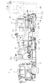
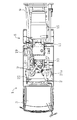
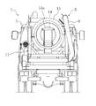
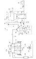
図1〜図3は、本発明の実施形態にかかる吸引回収車の側面図、平面図及び背面図である。図4は、吸引回収車のエア配管図である。図5乃至図7は、サイクロンを拡大して示す正面図、側面図及び底面図である。図8及び図9は、可動式仕切板及びサイクロン部下部の拡大正面図及び側面図である。図10は、サイロ及びその周辺の拡大側面図である。図11は、サイロ及びその周辺を拡大して示す底面図である。図12及び図13は、回収用開口周辺の拡大側面図である。図14は、回収容器の斜視図である。 1 to 3 are a side view, a plan view, and a rear view of a suction collection vehicle according to an embodiment of the present invention. FIG. 4 is an air piping diagram of the suction collection vehicle. 5 to 7 are a front view, a side view, and a bottom view showing the cyclone in an enlarged manner. 8 and 9 are an enlarged front view and a side view of the movable partition plate and the lower part of the cyclone section. FIG. 10 is an enlarged side view of the silo and its surroundings. FIG. 11 is an enlarged bottom view showing the silo and its periphery. 12 and 13 are enlarged side views around the collection opening. FIG. 14 is a perspective view of the collection container.
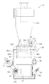
本発明の実施形態の吸引回収車1は、下部にエンジン2を有するキャブ3と、台車としてのシャシフレーム4とを備えている。シャシフレーム4上には、サブフレーム4aが搭載されている。
A suction collection vehicle 1 according to an embodiment of the present invention includes a
上記サブフレーム4a上には、本発明の実施形態にかかる吸引回収装置5が一体に設けられている。エンジン2には、動力取出装置(図示せず)が接続され、この動力取出装置により、油圧ポンプ(図示せず)及び後述するブロワ10が駆動されるように構成されている。
On the
具体的には、サブフレーム4aの前後中央部分には、吸引負圧を生じさせる吸引手段としてのブロワ10が搭載されている。ブロワ10は、大容量のガスを吸い込むことができるものとなっている。このブロワ10は、丸パイプ等で形成された接続配管9により、密閉状に吸引回収装置5内の各装置と連通されている。
Specifically, a
上記サブフレーム4aの後端には、サイロ15が設けられている。図10に拡大して示すように、サイロ15は、上側側面に吸引ホース8が接続される吸入口12を備え、上端の膨出部11の側面に排気口13を備えている。
A
上記サイロ15の下部は、密閉状の有底円筒容器型となり、その下部には、先細りとなった逆円錐部15aが形成されている。図11に示すように、サイロ15の下端部には、回収用開口14が形成されている。
The lower part of the
サイロ15は、吸引負圧により吸引された回収対象物としての活性炭50を含んだ吸引ガスを吸入口12から吸入し、旋回流を発生させて遠心分離作用によって質量の大きい活性炭50を回収してサイロ15の下部に集めると共に、残りのガスを排気口13から排出するように構成されている。活性炭50は、例えば、下水処理場で使用されて不純物が付着したものよりなる。
The
図11乃至図13にも示すように、回収用開口14は、サイロ15の底壁中央に形成された円形開口よりなり、この回収用開口14を円板状の蓋部材14aが開閉自在に覆っている。蓋部材14aは、蓋支持ピン14bに軸支され、この蓋支持ピン14bの反対側にウェイト部14cが設けられている。蓋支持ピン14bからウェイト部14cに一対の連結部14dが延びている。連結部14dの長さとウェイト部14cの質量とは、蓋部材14aを回収用開口14に隙間なく押さえ付ける程度に設定されている。吸引負圧が発生しているときには、蓋部材14aは回収用開口14に吸引されて密着しているが、吸引負圧がなくなると、サイロ15に蓄積された活性炭50の重力が加わって自動的に蓋部材14aが開くように構成されている。
As shown in FIGS. 11 to 13, the
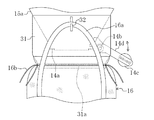
サイロ15の下部の逆円錐部15aは、スカート部材31で覆われている。例えば、このスカート部材31は、円筒形状を有し、サイロ15の下部に溶接されている。スカート部材31の下端部には、リング状の突条が外周に設けられたバッグ取付部31aが形成されている。
The inverted
スカート部材31には、活性炭50を回収する回収容器16が着脱自在に設けられるようになっている。図14に示すように、この回収容器16は、円形開口を有する有底の伸縮自在のフレキシブルコンテナバッグで構成されている。例えば、この回収容器16は、上部に2本の吊り部16aと、上端を巾着状に縛り付ける絞り部16bとを備えている。図12及び図13に示すように、スカート部材31には、吊り部16aを引っ掛ける係止部32が設けられ、この係止部32に吊り部16aを引っ掛けた状態で絞り部16bを絞り、回収容器16の上端をスカート部材31のバッグ取付部31aに密着させるように構成されている。この状態で、回収容器16が蓋部材14aの開閉動作を阻害しないようになっている。この回収容器16により、サイロ15に蓄積した活性炭50を回収し、例えば別のトラックに回収容器16を搭載して再生場に運搬される。回収された活性炭50は、乾燥されて再利用される。
The
図1,図10及び図11に示すように、サイロ15は、サブフレーム4aの後端に載置されたサイロ傾動手段17によって傾動自在に支持されている。サイロ傾動手段17は、サイロ15を支持する骨組状の支持部17aと、この支持部17aを傾動させる油圧シリンダ17bと、支持部17aを回転自在に支持する傾動軸17cとを備えている。この油圧シリンダ17bを縮めた状態で支持部17aに支持されたサイロ15がコンパクトな水平の格納状態となり、油圧シリンダ17bを伸ばした状態でサイロ15が起立されて回収状態となるように構成されている。
As shown in FIGS. 1, 10, and 11, the
図4乃至図7に示すように、上記排気口13の下流側には、サイクロン19が設けられている。本実施形態では、サブフレーム4aの前後中央よりの右側にサイクロン19が設けられている。サイクロン19は、内部で旋回流を生じさせる上部のサイクロン部19aと、その下側につながる容器状の集積部19bとを有している。サイクロン部19aの作用により、集積部19bにサイロ15の上部で回収されなかったガス内の微細な活性炭50等が蓄積される。サイクロン19には、集積部19bに堆積した活性炭50をブロワ10による吸引負圧により生じた気流を利用してサイロ15内に回収可能な回収経路29を接続又は遮断可能となっている。
As shown in FIGS. 4 to 7, a
具体的には、図8及び図9に示すように、サイクロン19は、上部のサイクロン部19aと集積部19bとを連通又は遮断する可動式仕切板40を備えている。なお、図8及び図9では、開いた状態の可動式仕切板40を実線で示し、閉じた状態は二点鎖線で示す。この可動式仕切板40は、集積部19bに回転可能に支持された揺動軸40aと、ハンドル40bと、ハンドル40bに連結された仕切板本体40cとを備えている。揺動軸40aは、集積部19bの内面に設けたボス部40dに回転自在に支持されている。このハンドル40bを揺動させることで、仕切板本体40cでサイクロン部19aの下部の開口周縁のフランジ部19eを閉じたり、開いたりすることで、サイクロン部19aと集積部19bとを連通又は遮断可能となっている。なお、本実施形態では、フランジ部19e側にパッキン19fが設けられているが、仕切板本体40c側に設けてもよい。
Specifically, as shown in FIGS. 8 and 9, the
また、集積部19bの底面19cは奥側から手前側に向かって下方へ傾斜している。集積部19bの下部には、奥側から手前側に向かって水平に延びる第1空気吸入管41aが接続されている。この第1空気吸入管41aの先端に、集積部19bと外気とを連通又は遮断する第1空気吸入弁41が設けられている。この第1空気吸入弁41は、ボールバルブよりなり、例えば、手動で開閉切換可能となっている。
Further, the
集積部19bにおける上記第1空気吸入弁41の上方には、第2空気吸入管47aが設けられ、この第2空気吸入管47aの外側先端に第1空気吸入弁41と同様のボールバルブよりなる第2空気吸入弁47が設けられている。
A second
また、集積部19bの第1空気吸入管41aと左右反対側には、この集積部19bに対して内側先端が底面19cの近傍まで真っ直ぐに延びるように排出管42aが差し込まれている。この排出管42aの外側先端には、回収経路29と集積部19bとを連通又は遮断する排出弁42が設けられている。排出弁42は、第1空気吸入弁41よりもサイズの大きなボールバルブよりなり、排出管42aは、第1空気吸入管41aよりも内径が大きいものよりなる。
In addition, a
このように構成することで、第1空気吸入弁41及び第2空気吸入弁47から外気を取り入れながら、集積部19bの内部で旋回流を発生させ、排出弁42に接続された吸引ホース8(回収経路29)からブロワ10による負圧により生じた気流で活性炭50が吸引されるようになっている。
With such a configuration, the suction hose 8 (the swirl flow is generated inside the accumulating
サイクロン19の可動式仕切板40の付近には、上側開閉扉43が設けられ、下部には、下側開閉扉44が設けられている。例えば、上側開閉扉43は、ボルトを緩めることで開閉可能であり、下側開閉扉44は、回転式ハンドル45を回転操作することで、開閉可能となっている。また、上側開閉扉43と下側開閉扉44との間には、活性炭50が満量となっているかを検知する満量検出センサ(図示せず)が取り付け可能なセンサ取付用フランジ46が設けられている。
An
図4に示すように、サイクロン19の下流側には、第1湿式集塵装置20が設けられている。同様にブロワ10の下流には、第2湿式集塵装置21が設けられている。これらの第1及び第2湿式集塵装置20,21は、共通する水タンク22を備え、この水タンク22内が第1湿式集塵装置20側と第2湿式集塵装置21側とに仕切板22aで仕切られている。排出ガスは、水タンク22内の液体に接触され、粉塵のみが捕捉されるように構成されている。具体的には図示しないが、第1湿式集塵装置20の吸入口から吸入された排出ガスに含まれる粉塵は、サイクロン部分で回収され、水タンク22の底部に蓄積されて水と共に回収される。粉塵が除かれたクリーンな排出ガスは、第1湿式集塵装置20外に排出され、接続配管9を通ってブロワ10に吸引されるようになっている。また、ブロワ10の吸引ガスには、霧状の冷却水が含まれており、第2湿式集塵装置21により、ブロワ10によって加熱された排出ガス内の水蒸気は、サイクロン部分で回収されて水タンク22内に流れ込み、排出口21aから水蒸気を含まないクリーンな排出ガスが排出されるようになっている。なお、第2湿式集塵装置21内の水は、ブロワ10の冷却水として再利用される。第1及び第2湿式集塵装置20,21が一体の水タンク22を備えることにより、第1及び第2湿式集塵装置20,21の設置スペースが小さくてすむ。なお、図2に示すように、省スペースの観点で平面視で第1及び第2湿式集塵装置20,21間の凹部にブロワ10が配置されている。
As shown in FIG. 4, a first
第1湿式集塵装置20とブロワ10との間及びブロワ10と第2湿式集塵装置21との間には、それぞれサイレンサ30が設けられている。第1湿式集塵装置20とサイレンサ30との間には、負圧開放弁33が設けられている。この負圧開放弁33は、第2湿式集塵装置21にも接続され、負圧開放弁33により、ブロワ10停止時の吸引回収装置5の全ての機器から負圧を開放し、大気圧状態とするようになっている。
図10及び図11にも示すように、サイロ15の上部には、活性炭50を回収容器16に回収するときにサイロ15内の負圧を開放にするための負圧開放路27が設けられている。負圧開放路27はサイロ15の上面から手動式バタフライバルブ28を介してサイレンサ30に連通している。このことで、手動式バタフライバルブ28を開くと、サイレンサ30で消音されながら、外気がサイロ15内に取り入れられるようになっている。
As shown in FIGS. 10 and 11, a negative
図1に示すように、吸引回収装置5の後側側面には、コントロールパネル24が設けられている。このコントロールパネル24により、動力取出装置、油圧ポンプ7、吸引回収装置5等が制御されるようになっている。このコントロールパネル24に吸引回収装置5内の圧力を表示するようにしてもよい。また、集積部19bの満量検出センサの検出信号を受けてコントロールパネル24上に警告表示をしたり、警報を発するようにしてもよい。
As shown in FIG. 1, a
−作動−
次に、本実施形態にかかる吸引回収装置5(吸引回収車1)の作動について説明する。
-Operation-
Next, the operation of the suction recovery device 5 (suction recovery vehicle 1) according to this embodiment will be described.
まず、図1に示すように、走行時には、エンジン2の駆動力により、吸引回収車1が走行する。このとき、サイロ傾動手段17により、サイロ15は、水平に傾けられ、サブフレーム4a上にコンパクトに載置されている。
First, as shown in FIG. 1, during the travel, the suction collection vehicle 1 travels by the driving force of the
回収場所では、まず、エンジン2を駆動し、コントロールパネル24を操作して、動力取出装置により、油圧ポンプ7及びブロワ10を駆動し、油圧ポンプ7の高圧油により、油圧シリンダ17bを伸ばして図1に2点鎖線で示すように、サイロ15を垂直に起立させる。吸入口12には吸引ホース8を接続しておく。
At the collection place, first, the
次いで、図12及び図13に示すように、回収容器16の吊り部16aをスカート部材31の係止部32に掛け、絞り部16bを絞って回収容器16をバッグ取付部31aに密着させて引っ掛け、作業姿勢が完成する。このように、本実施形態の吸引回収車1は、サイロ傾動手段17により、運搬時にはサイロ15を傾けてコンパクトにし、回収時にはサイロ15を起立させることができるので、起立時のサイロ15の高さを高くしても、高さ制限内で運搬が可能である。このため、サイロ15を別に設ける必要がなく、配管や操作が容易である。また、サイロ15のサイズを大きくすることができる。
Next, as shown in FIG. 12 and FIG. 13, the hanging
また、自走可能なサブフレーム4aに吸引回収装置5が一体に設けられているので、容易に回収場所に移動可能であると共に、吸引回収装置5の積み卸しをすることなく、吸引回収車1のエンジン2を利用して回収作業が行われる。
Further, since the
図4に示すように、回収作業においては、吸引ホース8の先端を下水処理場などで使用済みの不純物が付着した活性炭50に近付け、ブロワ10によって発生した吸引負圧を利用して吸引する。
As shown in FIG. 4, in the collection operation, the tip of the
すると、吸引力によって活性炭50がサイロ15の上部の吸入口12から吸い込まれる。
Then, the activated
次いで、サイロ15の上部内で活性炭50が含有された吸引ガスから旋回流の遠心力により、質量の大きい活性炭50が下部に選別され、残ったガスが上昇して排気口13より排出される。選別された活性炭50は、重力により下側に移動し、サイロ15の下部に堆積される。
Next, the activated
次いで、サイロ15内に一定量の活性炭50が溜まると、手動式バタフライバルブ28を開いて外気を取り入れ、サイロ15内の負圧を開放する。
Next, when a certain amount of activated
負圧が開放されると、ウェイト部14cの重力よりも蓋部材14a上に堆積した活性炭50の重力の方が大きいので、蓋部材14aが自動的に開いて回収容器16に活性炭50が回収される。回収後、この回収容器16を取り外して再生処理場へ運搬し、乾燥して活性炭50を再生する。
When the negative pressure is released, the gravity of the activated
活性炭50を回収中に、活性炭50は重力により落下するため、サイロ15下方に粉塵が舞う。しかし、回収容器16がスカート部材31のバッグ取付部31aに密着しているので、蓋部材14aの開閉動作を阻害することなく、大気中に粉塵が舞うのが確実に防止される。このようにして、活性炭50を効率よく回収しながら、活性炭50の粉塵が大気に排出されるのが防止される。
During the recovery of the activated
一方、排気口13から排出された排出ガスは、サイクロン19に吸引される。図8及び図9に示すように、通常の活性炭50の回収作業においては、可動式仕切板40を開き、排出弁42と第1空気吸入弁41及び第2空気吸入弁47を閉じている。そして、サイロ15の上部で回収しきれなかった活性炭50がサイクロン部19aの作用で回収されて図9の矢印の方向へ落下し、サイクロン19の集積部19bに堆積する。
On the other hand, the exhaust gas discharged from the
さらに、サイクロン19で、クリーンにされた排出ガスは、第1湿式集塵装置20に吸引され、サイクロン19で取りきれなかった微細な粉塵がさらに確実に回収される。このため、粉塵によりブロワ10が故障するのが防止される。
Further, the exhaust gas cleaned by the
次いで、ブロワ10により吸引された排出ガスには霧状の冷却水が含まれており、ブロワ10内で暖められるため、水蒸気が大量に含まれている。この水蒸気を含む排出ガスは、第2湿式集塵装置21を通過することによって、水蒸気が除去され、排出口21aから水蒸気が含まれないクリーンな排出ガスが排出される。また、第2湿式集塵装置21内の水はブロワ10の冷却水として再利用される。
Next, the exhaust gas sucked by the
そして、満量検出センサの検出により集積部19bの活性炭50の量が満杯に近付いたことが判明したときには、別の吸引ホース8をサイロ15の吸入口12と排出管42aにつなぎ、図9に二点鎖線で示すように、ハンドル40bを操作して可動式仕切板40を閉じ、さらに、排出弁42と第1空気吸入弁41及び第2空気吸入弁47とを開く。すると、図7に矢印で示すように、第1空気吸入弁41及び第2空気吸入弁47を通った空気が集積部19b内に入り込み、旋回流を発生させる。この旋回流の作用により、集積部19bの底面19c上に堆積した活性炭50が排出管42aの先端から効率よく吸い込まれ、回収経路29を通ってサイロ15内に回収される。このとき、回収容器16がサイロ15の下部に着脱自在に設けられるため、サイロ15及び集積部19bに溜まった活性炭50の回収及び回収後の運搬が容易である。このとき、他のコンプレッサ等の装置は必要としない。
When it is determined that the amount of the activated
−実施形態の効果−
したがって、本実施形態にかかる吸引回収車1によると、サイロ15の下流にサイクロン19を設け、このサイクロン19の下部に堆積した活性炭50を吸引負圧により生じた気流を利用して必要なときだけ回収経路29を通してサイロ15内に回収可能にし、また、サイクロン19に可動式仕切板40と排出弁42と第1空気吸入弁41及び第2空気吸入弁47とを設け、通常の活性炭50の回収作業においては回収経路29を集積部19bに接続せず、必要なときのみ回収経路29を接続するようにしたことにより、簡単な構成で吸引回収能力を低下させることなく、サイロ15の下流のサイクロン19に蓄積した活性炭50を効率よく回収することができる。
-Effect of the embodiment-
Therefore, according to the suction recovery vehicle 1 according to the present embodiment, the
また、第1空気吸入管41aを排出管42aとを左右対向する位置に配置して集積部19b内で旋回流を発生させるようにしたことにより、集積部19b内の活性炭50を効率よくサイロ15内に回収することができるので、回収作業の作業効率を向上させることができる。
Further, the first
また、集積部19bの上下に第1空気吸入弁41及び第2空気吸入弁47を設けたことにより、集積部19b内で効果的に旋回流を発生させ活性炭50を極めて効果よく回収することができる。
Further, by providing the first
また、サイロ傾動手段17によってサイロ15を傾動自在に支持し、運搬時にはサイロ15を傾け、回収時にはサイロ15を起立させるようにしたことにより、サイロ15を別に設ける必要がないので配管や操作が容易となり、サイロ15のサイズを大きくすることができる。
In addition, since the
また、排気口13の下流側にサイクロン19を設け、その下流に第1湿式集塵装置20を設けたことにより、排出ガス内の活性炭50等の粉塵を確実に回収してブロワ10の故障を防止することができるので、排出ガスがクリーンで故障しにくい吸引回収装置5が得られる。
Further, the
さらに、ブロワ10の下流に水蒸気を除去するための第2湿式集塵装置21を設けたことにより、水蒸気を含まないクリーンな排出ガスが得られるので、周囲を濡らすことなく快適に回収作業を行うことができると共に、第1及び第2湿式集塵装置20,21の水タンク22を共通のものとしたことにより、コンパクトな吸引回収装置5が得られる。
Furthermore, by providing the second
また、吸引回収車1は、吸引回収装置5が自走可能なキャブ3に一体に設けられているので、容易に回収場所に移動可能であると共に、吸引回収装置5の積み卸し作業をすることなく、すぐに回収作業を行うことができる。
Further, since the suction collection vehicle 1 is provided integrally with the
(その他の実施形態)
本発明は、上記実施形態について、以下のような構成としてもよい。
(Other embodiments)
The present invention may be configured as follows with respect to the above embodiment.
すなわち、上記実施形態では、吸引回収装置5が自走可能なサブフレーム4a上に一体に設けられた吸引回収車1について述べたが、独立エンジンを備え、自走車に搭載可能にユニット構成された吸引回収装置であってもよい。詳しくは図示しないが、上記実施形態と同様の構成の吸引回収装置をコンテナ状の台の上にユニット化して載置すれば、クレーン等により、自走車に搭載が可能となる。回収現場でこの吸引回収装置をクレーン等で降ろして設置することにより、容易に回収作業が行われる。このように構成すれば、独立エンジンを備えているので、自走車で回収場所に運搬し、外部動力を用いることなく、容易に活性炭50の回収を行うことができる。
That is, in the above-described embodiment, the suction collection vehicle 1 integrally provided on the
上記実施形態では、回収経路29を吸引ホース8で構成したが、金属製の固定パイプで構成してもよい。この場合には、固定パイプを排出弁42に常時接続し、吸入口12との間に三方向弁を設けて切断又は遮断可能に構成してもよい。
In the said embodiment, although the collection | recovery path |
上記実施形態における満量検出センサの検出信号を受け、自動的に集積部19b内の活性炭50をサイロ15に回収するようにしてもよい。この場合には、排出管42aに吸引ホース8を常時接続しておき、可動式仕切板40も自動で駆動するようにすればよい。
The activated
上記実施形態では、回収対象物は、活性炭50としたが、石炭、砂、セメント、各種廃棄物、豆等の穀物その他の粉体、粒状体、塊状体、片状体等であってもよい。
In the above embodiment, the collection target is activated
なお、以上の実施形態は、本質的に好ましい例示であって、本発明、その適用物や用途の範囲を制限することを意図するものではない。 In addition, the above embodiment is an essentially preferable illustration, Comprising: It does not intend restrict | limiting the range of this invention, its application thing, or a use.
以上説明したように、本発明は、下水処理場で使用済みの活性炭等の回収対象物を吸引負圧を利用して回収する吸引回収装置及びそれを備えた吸引回収車について有用である。 As described above, the present invention is useful for a suction recovery device that recovers a collection target such as activated carbon used in a sewage treatment plant by using a negative suction pressure, and a suction recovery vehicle including the same.
4 シャシフレーム(台車)
5 吸引回収装置
10 ブロワ(吸引手段)
13 排気口
15 サイロ
17 サイロ傾動手段
19 サイクロン
19a サイクロン部
19b 集積部
19c 底面
20 第1湿式集塵装置
21 第2湿式集塵装置
22 水タンク
29 回収経路
40 可動式仕切板
41 第1空気吸入弁
41a 第1空気吸入管
42 排出弁
42a 排出管
47 第2空気吸入弁
50 活性炭(回収対象物)
4 Chassis frame (cart)
5
DESCRIPTION OF
Claims (9)
吸引負圧を生じさせる吸引手段と、
上記吸引負圧により吸引された回収対象物を含んだ吸引ガスを旋回させながら回収対象物を回収して下部に収納すると共に、残りのガスを排気口から排出するサイロと、
上記サイロの下部に着脱自在に設けられ、上記サイロに収納された回収対象物を回収する回収容器と、
上記排気口の下流側に設けられ、上部に内部で旋回流を生じさせるサイクロン部及び該サイクロン部の下側に上記ガス内から回収した回収対象物を収納する集積部を有するサイクロンとを備え、
上記集積部には、該集積部に堆積した上記回収対象物を上記吸引負圧を利用して上記サイロ内に回収可能な回収経路が接続又は遮断可能に構成されている
ことを特徴とする吸引回収装置。 In the suction recovery device that sucks and recovers the recovery object,
A suction means for generating suction negative pressure;
A silo that collects the recovery object while swirling the suction gas containing the recovery object sucked by the suction negative pressure and stores it in the lower part, and discharges the remaining gas from the exhaust port,
A collection container that is detachably provided at the bottom of the silo and collects the collection object stored in the silo;
A cyclone that is provided on the downstream side of the exhaust port and has a cyclone part that generates a swirling flow in the upper part and a collecting part that stores a collection object collected from the gas below the cyclone part,
A suction path characterized in that the recovery path capable of recovering the collection object accumulated in the accumulation section into the silo by using the suction negative pressure is connectable to or cut off from the accumulation section. Recovery device.
上記サイクロンは、
上記サイクロン部と上記集積部とを連通又は遮断する可動式仕切板と、
上記集積部に配置され、上記回収経路と該集積部とを連通又は遮断する排出弁と、
上記集積部と外気とを連通又は遮断する空気吸入弁とを備えている
ことを特徴とする吸引回収装置。 The suction recovery apparatus according to claim 1,
The cyclone is
A movable partition plate for communicating or blocking the cyclone unit and the accumulation unit;
A discharge valve that is disposed in the stacking unit and communicates or blocks the collection path and the stacking unit;
A suction recovery apparatus, comprising: an air suction valve that communicates or shuts off the collecting unit and outside air.
上記集積部の底面は、奥側から手前側に向かって下方へ傾斜し、
上記空気吸入弁は、水平に延びて上記集積部に差し込まれた空気吸入管に接続され、
上記排出弁は、上記空気吸入管と左右反対側で上記集積部に差し込まれ、先端が上記底面近傍まで延びた排出管に接続されている
ことを特徴とする吸引回収装置。 The suction recovery apparatus according to claim 2,
The bottom surface of the accumulation part is inclined downward from the back side toward the near side,
The air intake valve is connected to an air intake pipe that extends horizontally and is inserted into the accumulation portion,
The suction recovery apparatus according to claim 1, wherein the discharge valve is inserted into the collecting portion on the opposite side to the air suction pipe, and is connected to a discharge pipe whose tip extends to the vicinity of the bottom surface.
上記集積部の上側に第2の空気吸入弁が設けられている
ことを特徴とする吸引回収装置。 In the suction collection device according to claim 3,
A suction recovery device, wherein a second air suction valve is provided above the accumulation portion.
上記サイロを傾動自在に支持するサイロ傾動手段を備えている
ことを特徴とする吸引回収装置。 In the suction collection device according to any one of claims 1 to 4,
A suction recovery apparatus comprising silo tilting means for tiltably supporting the silo.
上記吸引手段は、ブロワよりなり、
上記サイクロンの下流側に湿式集塵装置が設けられている
ことを特徴とする吸引回収装置。 In the suction collection device according to any one of claims 1 to 5,
The suction means comprises a blower,
A suction recovery apparatus, wherein a wet dust collector is provided downstream of the cyclone.
上記ブロワの下流には、第2の湿式集塵装置が設けられ、該第2の湿式集塵装置と上記湿式集塵装置とは一体の水タンクを備えている
ことを特徴とする吸引回収装置。 The suction recovery device according to claim 6,
A suction and recovery device, wherein a second wet dust collector is provided downstream of the blower, and the second wet dust collector and the wet dust collector are provided with an integrated water tank. .
独立エンジンを備え、自走車に搭載可能にユニット構成されている
ことを特徴とする吸引回収装置。 In the suction collection device according to any one of claims 1 to 7,
A suction recovery device comprising an independent engine and configured as a unit that can be mounted on a self-propelled vehicle.
上記吸引回収装置は、自走可能な台車上に一体に設けられている
ことを特徴とする吸引回収車。 A suction recovery device according to any one of claims 1 to 7,
The suction recovery vehicle is characterized in that the suction recovery device is integrally provided on a self-propelled carriage.
Priority Applications (1)
| Application Number | Priority Date | Filing Date | Title |
|---|---|---|---|
| JP2008062644A JP5119014B2 (en) | 2008-03-12 | 2008-03-12 | Suction recovery device and suction recovery vehicle equipped with the same |
Applications Claiming Priority (1)
| Application Number | Priority Date | Filing Date | Title |
|---|---|---|---|
| JP2008062644A JP5119014B2 (en) | 2008-03-12 | 2008-03-12 | Suction recovery device and suction recovery vehicle equipped with the same |
Publications (2)
| Publication Number | Publication Date |
|---|---|
| JP2009215035A JP2009215035A (en) | 2009-09-24 |
| JP5119014B2 true JP5119014B2 (en) | 2013-01-16 |
Family
ID=41187325
Family Applications (1)
| Application Number | Title | Priority Date | Filing Date |
|---|---|---|---|
| JP2008062644A Active JP5119014B2 (en) | 2008-03-12 | 2008-03-12 | Suction recovery device and suction recovery vehicle equipped with the same |
Country Status (1)
| Country | Link |
|---|---|
| JP (1) | JP5119014B2 (en) |
Families Citing this family (3)
| Publication number | Priority date | Publication date | Assignee | Title |
|---|---|---|---|---|
| CN103063036A (en) * | 2013-01-29 | 2013-04-24 | 韩旭新 | Device for negative-pressure sucking, conveying and discharging of sintered bulk materials of multi-tube tunnel kiln car |
| CN113200361A (en) * | 2021-04-26 | 2021-08-03 | 苏州美一杯信息科技有限公司 | Sand recovery device |
| KR102567691B1 (en) * | 2022-08-23 | 2023-08-16 | 전인설 | Filtration material injection system through suction |
Family Cites Families (6)
| Publication number | Priority date | Publication date | Assignee | Title |
|---|---|---|---|---|
| JPS58222230A (en) * | 1982-06-17 | 1983-12-23 | Hakko Co Ltd | Vacuum discharger of soil and sand |
| JPS6079555U (en) * | 1983-11-04 | 1985-06-03 | 住友金属工業株式会社 | Dust remover dust receiving and discharging device |
| JPH01148380A (en) * | 1987-12-01 | 1989-06-09 | Morita Tokushu Kiko Co Ltd | Asbestos recovery apparatus |
| JPH089402B2 (en) * | 1992-09-11 | 1996-01-31 | 有限会社やまと水研 | Dust recycling device in vehicle-mounted vacuum suction device |
| JPH07187404A (en) * | 1993-11-17 | 1995-07-25 | Morita Tokushu Kiko Kk | Sand replacing method |
| JP3027439U (en) * | 1996-01-31 | 1996-08-09 | レオン自動機株式会社 | Powder discharge device |
-
2008
- 2008-03-12 JP JP2008062644A patent/JP5119014B2/en active Active
Also Published As
| Publication number | Publication date |
|---|---|
| JP2009215035A (en) | 2009-09-24 |
Similar Documents
| Publication | Publication Date | Title |
|---|---|---|
| US3973935A (en) | Dust filtration system | |
| US5596788A (en) | Vacuum sweeper vehicle with lightweight hopper | |
| US3541631A (en) | Industrial vacuum loader and cleaner | |
| EP1481133A1 (en) | Debris collection systems, vehicles, and methods | |
| US5002595A (en) | Debris and water vacuum system | |
| US3404776A (en) | Apparatus for collecting loose materials in a portable collector | |
| JP5119014B2 (en) | Suction recovery device and suction recovery vehicle equipped with the same | |
| US20040003481A1 (en) | Apparatus and method for collection of debris | |
| JP5024869B2 (en) | Powder suction collection vehicle | |
| JP2008179455A (en) | Suction recovery device and suction recovery vehicle having this device | |
| CN204282271U (en) | A kind of road-sweeper dust arrester | |
| US20040177470A1 (en) | Apparatus and method for collection of debris | |
| JP2008184258A (en) | Suction recovery device, and suction recovery vehicle equipped therewith | |
| JP4231774B2 (en) | Garbage truck | |
| CN209668707U (en) | A kind of fork truck automatic cleaner | |
| CN208429008U (en) | Single-point discharging vacuum sweeper | |
| JP4013141B2 (en) | Suction car | |
| JP6862048B2 (en) | Suction car | |
| CA2352619C (en) | Mud tank cleaning system | |
| JP6400520B2 (en) | Working machine | |
| US20220220682A1 (en) | Dry filtration system | |
| CN213358459U (en) | Cantilever crane suction car | |
| JP2018204430A (en) | Work machine | |
| JP2006096509A (en) | Suction recovery system | |
| CN214363696U (en) | Loader with wet dust removal device |
Legal Events
| Date | Code | Title | Description |
|---|---|---|---|
| A621 | Written request for application examination |
Free format text: JAPANESE INTERMEDIATE CODE: A621 Effective date: 20101026 |
|
| A521 | Request for written amendment filed |
Free format text: JAPANESE INTERMEDIATE CODE: A523 Effective date: 20111216 |
|
| RD02 | Notification of acceptance of power of attorney |
Free format text: JAPANESE INTERMEDIATE CODE: A7422 Effective date: 20120127 |
|
| A977 | Report on retrieval |
Free format text: JAPANESE INTERMEDIATE CODE: A971007 Effective date: 20120925 |
|
| TRDD | Decision of grant or rejection written | ||
| A01 | Written decision to grant a patent or to grant a registration (utility model) |
Free format text: JAPANESE INTERMEDIATE CODE: A01 Effective date: 20121002 |
|
| A01 | Written decision to grant a patent or to grant a registration (utility model) |
Free format text: JAPANESE INTERMEDIATE CODE: A01 |
|
| A61 | First payment of annual fees (during grant procedure) |
Free format text: JAPANESE INTERMEDIATE CODE: A61 Effective date: 20121022 |
|
| R150 | Certificate of patent or registration of utility model |
Ref document number: 5119014 Country of ref document: JP Free format text: JAPANESE INTERMEDIATE CODE: R150 Free format text: JAPANESE INTERMEDIATE CODE: R150 |
|
| FPAY | Renewal fee payment (event date is renewal date of database) |
Free format text: PAYMENT UNTIL: 20151026 Year of fee payment: 3 |
|
| FPAY | Renewal fee payment (event date is renewal date of database) |
Free format text: PAYMENT UNTIL: 20151026 Year of fee payment: 3 |
|
| R250 | Receipt of annual fees |
Free format text: JAPANESE INTERMEDIATE CODE: R250 |
|
| R250 | Receipt of annual fees |
Free format text: JAPANESE INTERMEDIATE CODE: R250 |
|
| R250 | Receipt of annual fees |
Free format text: JAPANESE INTERMEDIATE CODE: R250 |
|
| R250 | Receipt of annual fees |
Free format text: JAPANESE INTERMEDIATE CODE: R250 |
|
| R250 | Receipt of annual fees |
Free format text: JAPANESE INTERMEDIATE CODE: R250 |
|
| R250 | Receipt of annual fees |
Free format text: JAPANESE INTERMEDIATE CODE: R250 |
|
| R250 | Receipt of annual fees |
Free format text: JAPANESE INTERMEDIATE CODE: R250 |
|
| R250 | Receipt of annual fees |
Free format text: JAPANESE INTERMEDIATE CODE: R250 |