JP5118686B2 - Seismic reinforcement wall - Google Patents
Seismic reinforcement wall Download PDFInfo
- Publication number
- JP5118686B2 JP5118686B2 JP2009282670A JP2009282670A JP5118686B2 JP 5118686 B2 JP5118686 B2 JP 5118686B2 JP 2009282670 A JP2009282670 A JP 2009282670A JP 2009282670 A JP2009282670 A JP 2009282670A JP 5118686 B2 JP5118686 B2 JP 5118686B2
- Authority
- JP
- Japan
- Prior art keywords
- plate portion
- wall
- plate
- connecting member
- connection
- Prior art date
- Legal status (The legal status is an assumption and is not a legal conclusion. Google has not performed a legal analysis and makes no representation as to the accuracy of the status listed.)
- Active
Links
Images


Landscapes
- Working Measures On Existing Buildindgs (AREA)
Description
本発明は、既存建物に後付けされる耐震補強壁に関する。 The present invention relates to a seismic reinforcement wall retrofitted to an existing building.
既存建物に後付けされる耐震補強壁としては、例えば特許文献1に開示されたものがある。特許文献1の技術は、複数の軽量C形鋼を上下方向に積み上げて耐震補強壁を形成するという技術であり、上下に隣り合う軽量C形鋼のフランジ同士を高力ボルト等によって緊結することで、一体化を図っている。
As an earthquake-proof reinforcement wall retrofitted to an existing building, there exists a thing disclosed by
特許文献1の耐震補強壁では、隣り合う軽量C形鋼のフランジ同士を重ね合せる必要があるところ、軽量C形鋼のフランジは、補強すべき構面に交差するように配置されているので、2枚のフランジを重ね合せた様子を室内側から看取できてしまい、建物利用者に重厚な印象を与えてしまう。また、特許文献1の耐震補強壁では、多数の高力ボルトがフランジの上下に突出することになるので、2枚のフランジが重ね合されていることと相俟って、室内空間の美観を損ねる虞がある。
In the seismic reinforcement wall of
このような観点から、本発明は、複数の部材を組み合せて構成される耐震補強壁であって、重厚な印象を緩和することが可能な耐震補強壁を提供することを課題とする。 From such a viewpoint, an object of the present invention is to provide a seismic reinforcing wall that is configured by combining a plurality of members and that can relieve a heavy impression.
前記課題を解決する本発明は、補強すべき構面に沿って並設される複数の壁面板と、左右に隣り合う前記壁面板同士を接合する連結部材とを備える耐震補強壁であって、前記連結部材は、前記構面に沿って配置される接続プレート部と、前記構面に交差するように配置される補剛プレート部とを有し、前記接続プレート部に前記壁面板が重ね合されており、前記壁面板と前記接続プレート部とを貫通する高力ボルトによって、前記壁面板と前記接続プレート部とが摩擦接合されている、ことを特徴とする。 The present invention for solving the above problems is a seismic reinforcement wall comprising a plurality of wall plates arranged side by side along the construction surface to be reinforced, and a connecting member that joins the wall plates adjacent to each other on the left and right. The connecting member has a connection plate portion arranged along the composition surface and a stiffening plate portion arranged so as to intersect the composition surface, and the wall plate overlaps the connection plate portion. The wall surface plate and the connection plate portion are frictionally joined by a high-strength bolt that penetrates the wall surface plate and the connection plate portion.
「補強すべき構面」とは、既存建物の躯体(柱、梁、壁、床スラブなど)に囲まれた仮想上の鉛直面である。
本発明では、連結部材の接続プレート部に壁面板を重ね合わせた状態で、両者を高力ボルトにより摩擦接合しているが、重ね合せる部位(壁面板および接続プレート部)を構面に沿って配置しているので、壁面板と接続プレート部を重ね合せた様子が室内側から看取され難くなる。また、本発明では、補剛プレート部同士を重ね合せるという構成を採用していないので、補剛プレート部同士を摩擦接合するための高力ボルトが不要となる。なお、補剛プレート部は、接続プレート部の面外座屈を抑制するとともに、接続プレート部に接合された壁面板の面外座屈を抑制する構造要素である。
The “structural surface to be reinforced” is a virtual vertical plane surrounded by a frame of an existing building (column, beam, wall, floor slab, etc.).
In the present invention, the wall plate is overlapped with the connection plate portion of the connecting member, and both are friction-joined by high-strength bolts. However, the overlapping portion (wall plate and connection plate portion) is along the surface. Since it arrange | positions, it will become difficult to observe a mode that the wall surface board and the connection plate part were overlapped from the indoor side. Moreover, in this invention, since the structure which overlaps stiffening plate parts is not employ | adopted, the high strength volt | bolt for frictionally joining stiffening plate parts is unnecessary. The stiffening plate portion is a structural element that suppresses out-of-plane buckling of the connection plate portion and suppresses out-of-plane buckling of the wall plate joined to the connection plate portion.
前記連結部材に、前記接続プレート部および前記補剛プレート部の下端に接合された下端プレート部と、前記接続プレート部および前記補剛プレート部の上端に接合された上端プレート部とを具備させてもよい。このようにすると、複数の連結部材を並べた際に、複数の下端プレート部が左右方向に連なるとともに、複数の上端プレート部が左右方向に連なるので、下端プレート部および上端プレート部を耐震補強壁の外周枠として利用することができる。 The connecting member includes a lower end plate portion joined to lower ends of the connection plate portion and the stiffening plate portion, and an upper end plate portion joined to upper ends of the connection plate portion and the stiffening plate portion. Also good. In this way, when the plurality of connecting members are arranged, the plurality of lower end plate portions are connected in the left-right direction and the plurality of upper end plate portions are connected in the left-right direction. Can be used as an outer peripheral frame.
前記壁面板は、前記接続プレート部の前面および後面のいずれに重ね合せても差し支えないが、接続プレート部の前面に重ね合せると、接続プレート部が壁面板で覆い隠されるようになるので、接続プレート部の後面に重ね合せる場合よりも、すっきりとした外観となる。なお、壁面板を接続プレート部の前面に重ね合せた場合には、隣り合う前記壁面板の間から、前記補剛プレート部を前記壁面板の前側に突出させればよい。 The wall plate may be superimposed on either the front surface or the rear surface of the connection plate portion. However, if the wall plate is superimposed on the front surface of the connection plate portion, the connection plate portion will be covered with the wall plate. It has a cleaner appearance than when it is superimposed on the rear surface of the plate portion. When the wall plate is superimposed on the front surface of the connection plate portion, the stiffening plate portion may be protruded to the front side of the wall plate between the adjacent wall plates.
耐震補強壁に窓部を設ける場合には、窓部が形成された窓付きユニットを組み合せるとよい。窓付きユニットの構成に制限はないが、前記窓部の左右両側に配置された縦枠プレート部と、隣り合う前記縦枠プレート部間に配置されたブレース部と、前記縦枠プレート部の外側面に沿って配置されたエンドプレート部とを備えるものを利用すれば、ブレース部によってせん断力を伝達することが可能になるので、大きな窓部を形成することが可能となる。 When a window is provided on the seismic reinforcement wall, a unit with a window formed with a window may be combined. The configuration of the unit with a window is not limited, but the vertical frame plate portions disposed on the left and right sides of the window portion, the brace portions disposed between the adjacent vertical frame plate portions, and the outside of the vertical frame plate portion. If a thing provided with the end plate part arrange | positioned along a side surface is utilized, since it will become possible to transmit a shear force by a brace part, it will become possible to form a big window part.
前記窓付きユニットと前記壁面板とを接合する場合には、前記エンドプレート部に前記壁面板を重ね合せ、前記壁面板と前記エンドプレート部とを貫通する高力ボルトによって、前記壁面板と前記エンドプレート部とを摩擦接合するとよい。このようにすると、壁面板とエンドプレート部を重ね合せた様子が室内側から看取され難くなる。 When joining the unit with a window and the wall plate, the wall plate is overlaid on the end plate portion, and the wall plate and the wall plate by the high-strength bolt that penetrates the wall plate and the end plate portion. The end plate portion may be friction bonded. If it does in this way, it will become difficult to observe a mode that the wall plate and the end plate part were piled up from the indoor side.
前記壁面板の前側に前記高力ボルトを覆い隠す化粧背板を配置し、前記化粧背板の前面に棚板を設けてもよい。このようにすると、耐震補強壁を書架や飾り棚として利用することが可能になる。また、化粧背板によって高力ボルトを覆い隠されるので、すっきりとした外観となる。なお、連結部材の補剛プレート部や窓付きユニットの縦枠プレート部は、ブックエンド等として利用することができる。 A makeup back plate that covers the high-strength bolt may be disposed on the front side of the wall surface plate, and a shelf plate may be provided on the front surface of the makeup back plate. If it does in this way, it will become possible to use an earthquake-proof reinforcement wall as a bookshelf or a display shelf. Moreover, since the high-strength bolt is covered by the decorative back plate, a clean appearance is obtained. Note that the stiffening plate portion of the connecting member and the vertical frame plate portion of the windowed unit can be used as a book end or the like.
複数の壁面板を上下に並設した場合には、上下に隣り合う前記壁面板同士を接合する中間横架材を配置すればよい。この場合、前記中間横架材は、前記構面に沿って配置される縦プレート部と、前記構面に交差するように配置される横プレート部とを備えるものを使用し、前記縦プレート部に前記壁面板を重ね合せ、前記壁面板と前記縦プレート部とを貫通する高力ボルトによって、前記壁面板と前記縦プレート部とを摩擦接合することが望ましい。 When a plurality of wall surface plates are arranged side by side, an intermediate horizontal member for joining the wall surface plates adjacent to each other in the vertical direction may be disposed. In this case, the intermediate horizontal member uses a vertical plate portion disposed along the composition surface and a horizontal plate portion disposed so as to intersect the composition surface, and the vertical plate portion is used. It is desirable that the wall surface plate and the vertical plate portion be friction-joined with a high-strength bolt that penetrates the wall surface plate and the vertical plate portion.
本発明に係る耐震補強壁によれば、重厚な印象を緩和することが可能となる。 According to the seismic reinforcement wall according to the present invention, it is possible to relieve a heavy impression.
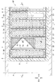
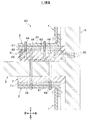
図1に示す耐震補強壁W1は、既存建物の室内に後付けされるものである。図2に示すように、本実施形態の耐震補強壁W1は、上下に隣り合う既存床スラブS,Sと、左右に隣り合う既存柱P,P(図2では左側の既存柱Pのみを図示)とで囲まれた空間に設置される。 The seismic reinforcement wall W1 shown in FIG. 1 is retrofitted into the room of an existing building. As shown in FIG. 2, the seismic reinforcement wall W1 of the present embodiment is illustrated with the existing floor slabs S, S adjacent to each other vertically and the existing columns P, P adjacent to the left and right (in FIG. 2, only the existing column P on the left side is illustrated. ).
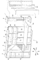
本実施形態では、既存建物の窓際の既存壁K(図3参照)に沿って耐震補強壁W1を設置する場合を例示するが、耐震補強壁W1の設置場所を限定する趣旨ではない。また、本実施形態では、既存柱P,Pと既存床スラブS,Sとで囲まれた空間に耐震補強壁W1を設置する場合を例示するが、既存の柱梁架構で囲まれた空間に耐震補強壁W1を設置しても勿論差し支えない。 In this embodiment, although the case where the earthquake-proof reinforcement wall W1 is installed along the existing wall K (refer FIG. 3) by the window of the existing building is illustrated, it is not the meaning which limits the installation place of the earthquake-proof reinforcement wall W1. In the present embodiment, the case where the earthquake-proof reinforcement wall W1 is installed in the space surrounded by the existing columns P and P and the existing floor slabs S and S is illustrated, but the space surrounded by the existing column beam frame is illustrated. Of course, the earthquake-proof reinforcement wall W1 may be installed.
図1に示すように、耐震補強壁W1は、補強すべき構面(以下、「補強構面」という。)に沿って並設される複数の壁面板1,1,…と、隣り合う壁面板1,1を接合する連結部材2,2,…と、既存建物の開口(窓)に対応する位置に配置される窓付きユニット3と、耐震補強壁W1の側縁部に配置される側縁部材4と、を備えている。
As shown in FIG. 1, the seismic reinforcement wall W <b> 1 is adjacent to a plurality of
壁面板1は、せん断力を伝達可能な構造材である。本実施形態の壁面板1は、縦長の長方形を呈する鋼板からなり、その長手方向が上下方向となるように配置されている。壁面板1は、その前面および後面が他の壁面板1の前面および後面と面一になるように配置されている(図3参照)。壁面板1の外周部には、ボルト挿通孔(図示略)が複数形成されている。このボルト挿通孔には、高力ボルトBが挿通される。本実施形態の高力ボルトBは、壁面板1の前側に突出した軸部へのナットの締め付けのみで締結力を導入可能なワンサイドボルトである。
The
連結部材2は、せん断力を伝達可能な構造材であり、接続プレート部21と、補剛プレート部22と、下端プレート部23と、上端プレート部24とを備えている。本実施形態の連結部材2は、CT形鋼(カットT形鋼)を利用して形成されている。すなわち、CT形鋼のフランジにより接続プレート部21が形成されており、CT形鋼のウェブにより補剛プレート部22が形成されている。
The connecting
接続プレート部21は、せん断力を伝達可能な板状の構造要素であり、補強構面に沿って配置される。接続プレート部21には、ボルト挿通孔21aが複数形成されている。ボルト挿通孔21aには、高力ボルトBが挿通される。図3にも示すように、接続プレート部21の前面には、壁面板1が重ね合されていて、壁面板1と接続プレート部21とを貫通する高力ボルトBによって、壁面板1と接続プレート部21とが摩擦接合されている。なお、左右に隣り合う壁面板1,1のうち、左側の壁面板1は、接続プレート部21の左半分(補剛プレート部22の左側の部分)に重ね合されており、右側の壁面板1は、接続プレート部21の右半分(補剛プレート部22の右側の部分)に重ね合されている。
The
補剛プレート部22は、補強構面に交差するように配置される板状の構造要素であり、接続プレート部21と一体になっている。補剛プレート部22は、接続プレート部21の面外座屈を抑制するとともに、接続プレート部21に接合された壁面板1の面外座屈を抑制する。本実施形態の補剛プレート部22は、接続プレート部21の前面に壁面板1,1が重ね合されている関係で、隣り合う壁面板1,1の間から、壁面板1,1の前側に突出している。
The
下端プレート部23は、図1に示すように、平面視矩形状の鋼板からなり、接続プレート部21および補剛プレート部22の下端に接合されている。下端プレート部23は、耐震補強壁W1の外周枠の下辺部の一部となる。
As shown in FIG. 1, the lower
上端プレート部24は、平面視矩形状の鋼板からなり、接続プレート部21および補剛プレート部22の上端に接合されている。上端プレート部24は、耐震補強壁W1の外周枠の上辺部の一部となる。
The upper
窓付きユニット3は、窓部3a,3b,3cを有する構造材であり、縦枠プレート部31と、下枠プレート部32と、上枠プレート部33と、中間プレート部34と、ブレース部35と、エンドプレート部36と、背面プレート部37とを備えている。窓付きユニット3は、CT形鋼や鋼板を利用して形成されている。
The
縦枠プレート部31は、補強構面に交差するように配置される板状の構造要素であり、窓部3a,3b,3cの左右両側に配置されている。左右一対の縦枠プレート31,31は、下枠プレート部32に立設されており、窓部3a,3b,3cを挟んで対峙している。
The vertical
下枠プレート部32は、一対の縦枠プレート31,31の下側に配置された板状の構造要素であり、耐震補強壁W1の外周枠の下辺部の一部となる。下枠プレート部32の左右の端部は、それぞれ縦枠プレート31の側方に延出している。
The lower
上枠プレート部33は、一対の縦枠プレート31,31の上側に配置された板状の構造要素であり、耐震補強壁W1の外周枠の上辺部の一部となる。上枠プレート部33の左右の端部は、それぞれ縦枠プレート31の側方に延出している。
The upper
中間プレート部34は、窓部3a,3b,3cの下側に配置された板状の構造要素であり、下枠プレート部32および上枠プレート部33の間において左右の縦枠プレート31,31を繋いでいる。本実施形態の中間プレート部34は、下枠プレート部32および上枠プレート部33と平行に配置されている。
The
ブレース部35は、窓部3a,3b,3cを取り囲む枠状架構のせん断変形を抑制するための構造要素であり、縦枠プレート部31,31の間に配置されている。本実施形態では、縦枠プレート部31,31、上枠プレート部33および中間プレート部34で形成される枠状架構内に二つのブレース部35,35が配置されている。二つのブレース部35,35は、横向きV字を形成するように組み合わされている。
The
エンドプレート部36は、せん断力を伝達可能な板状の構造要素であり、補強構面に沿って配置される。本実施形態のエンドプレート部36は、縦枠プレート部31の外側面に沿って形成されている。エンドプレート部36には、ボルト挿通孔(図示略)が複数形成されている。このボルト挿通孔には、高力ボルトBが挿通される。図3にも示すように、エンドプレート部36の前面には、壁面板1が重ね合されていて、壁面板1とエンドプレート部36とを貫通する高力ボルトBによって、壁面板1とエンドプレート部36とが摩擦接合されている。
The
背面プレート部37は、図1に示すように、ブレース部35の無い架構(縦枠プレート部31,31、下枠プレート部32および中間プレート部34で形成される矩形枠状の架構)のせん断変形を抑制するための構造要素であり、補強構面に沿って配置される。
As shown in FIG. 1, the
なお、窓部3a,3b,3cは、単なる開口部としてもよいし、非構造要素(孔あき鋼板、透明また透光性のガラス板やアクリル板など)によって閉塞してもよい。本実施形態では、窓部3aを単なる開口部とし、窓部3b,3cを孔あき鋼板38で閉塞している。
Note that the
側縁部材4は、せん断力を伝達可能な構造材であり、耐震補強壁W1の外周枠の側辺部となる。本実施形態の側縁部材4は、接続プレート部41と、補剛プレート部42と、下端プレート部43と、上端プレート部44とを備えている。接続プレート部41は、補強構面に沿って配置されており、補剛プレート部42は、補強構面に交差するように配置されている。本実施形態の側縁部材4は、CT形鋼(カットT形鋼)を利用して形成されている。
The
図2に示すように、本実施形態の耐震補強壁W1は、既存建物の躯体に囲まれた空間に配置される。耐震補強壁W1を設置する階の既存床スラブSと耐震補強壁W1の下面との間には増設梁6が形成されており、上階の既存床スラブSと耐震補強壁W1の上面との間には充填材7が充填されている。また、耐震補強壁W1と既存柱Pとの間には増設柱8が形成されている。
As shown in FIG. 2, the seismic reinforcement wall W1 of this embodiment is arrange | positioned in the space enclosed by the frame of the existing building. An
増設梁6は、耐震補強壁W1の台座となる鉄筋コンクリート製の構造体である。本実施形態の増設梁6は、図4に示すように、既存壁Kに植設されたせん断伝達部材(例えば、後施工アンカー)65を介して既存壁Kの壁面に固着されている。なお、増設梁6を省略し、既存床スラブS上に耐震補強壁W1を直接設置しても差し支えない。
The
図2に示すように、増設梁6の上面部には、台座プレート61,61,…が埋め込まれている。台座プレート61は、連結部材2または窓付きユニット3の取付座になる部材であり、鋼板にて形成されている。本実施形態では、一つの台座プレート61に対して、一の連結部材2の下端プレート部23と、その隣に位置する他の連結部材2の下端プレート部23または窓付きユニット3の下枠プレート部32とが固定されている。すなわち、複数の台座プレート61,61,…のうち、左右に隣り合う連結部材2,2の境界部分の下側に配置された台座プレート61は、連結部材2,2の共通の取付座になるとともに、連結部材2,2の下端同士を連結しており、連結部材2と窓付きユニット3との境界部分の下側に配置された台座プレート61は、連結部材2および窓付きユニット3の共通の取付座になるとともに、連結部材2と窓付きユニット3の下端同士を連結している。なお、左右方向に連ねられた複数の下端プレート部23,23,…と、下枠プレート部32と、台座プレート61,61,…とによって構成される構造体が、耐震補強壁W1の外周枠の下辺部となる。
As shown in FIG. 2,
台座プレート61は、図4に示すように、アンカーボルト62を利用して増設梁6のコンクリートに固定されている。なお、図2では、アンカーボルト62の図示を省略している。アンカーボルト62は、台座プレート61の下面に固着されたナット63に螺着されており、ナット63の上側の部分が台座プレート61に貫設され、ナット63の下側の部分が増設梁6のコンクリートに埋設される。なお、台座プレート61の上面に連結部材2(または窓付きユニット3)を載置し、下端プレート部23(または下枠プレート部32)の上側に突出させたアンカーボルト62にナット64を螺着すると、下端プレート部23(または下枠プレート部32)が台座プレート61の上面に固定される。
As shown in FIG. 4, the
図2に示すように、窓付きユニット3の中央部の下側には、台座プレート61が配置されていない。この部分では、増設梁6のコンクリート面に窓付きユニット3の下枠プレート部32を直に載置し、図5に示すように、アンカーボルト62を利用して下枠プレート部32を増設梁6に固定する。
As shown in FIG. 2, the
充填材7は、耐震補強壁W1の上面と上階の既存床スラブSの下面との隙間を閉塞するものであり、本実施形態では、無収縮モルタルからなる。
The
図2に示すように、充填材7の下面部には、天端プレート71,71,…が埋め込まれている。天端プレート71は、鋼板にて形成されている。本実施形態では、一つの天端プレート71に対して、一の連結部材2の上端プレート部24と、その隣に位置する他の連結部材2の上端プレート部24または窓付きユニット3の上枠プレート部33とが固定されている。すなわち、複数の天端プレート71,71,…のうち、連結部材2,2の境界部分を跨ぐように配置された天端プレート71は、連結部材2,2の上端同士を連結しており、連結部材2と窓付きユニット3との境界部分を跨ぐように配置された天端プレート71は、連結部材2と窓付きユニット3の上端同士を連結している。なお、左右方向に連ねられた複数の上端プレート部24,24,…と、上枠プレート部33と、天端プレート71,71,…とによって構成される構造体が、耐震補強壁W1の外周枠の上辺部となる。
As shown in FIG. 2,
天端プレート71は、図4に示すように、アンカーボルト66を利用して連結部材2(または窓付きユニット3)の上面に固着されている。すなわち、上端プレート部24(または上枠プレート部33)の上面に天端プレート71を載置した状態で、天端プレート71の上面に固着されたナット67にアンカーボルト66を螺着し、上端プレート部24(または上枠プレート部33)の下側に突出させたアンカーボルト66にナット68を螺着すると、天端プレート部71が上端プレート部24(または上枠プレート部33)の上面に固定される。なお、天端プレート71は、充填材7を打設する前に連結部材2または窓付きユニット3に固定する。
As shown in FIG. 4, the
アンカーボルト66は、既存床スラブSに設けた貫通孔に挿通され、アンカーボルト66の上端部は、増設梁6のコンクリートに埋設される。貫通孔には、無収縮グラウトが注入される。なお、図2では、アンカーボルト66の図示を省略している。
The
図2に示すように、窓付きユニット3の中央部の上側には、天端プレート71が配置されていない。この部分では、図5に示すように、アンカーボルト66の下端部に上枠プレート部33を固定する。
As shown in FIG. 2, the
増設柱8は、図3に示すように、鉄筋コンクリート製の構造体であり、既存柱Pに植設されたせん断伝達部材81を介して既存柱Pに固着されている。増設柱8のコンクリートは、無収縮タイプのコンクリートである。なお、側縁部材4の外側面には、せん断伝達部材43が固着されており、せん断伝達部材43を増設柱8のコンクリートに埋設することで、側縁部材4と増設柱8との一体化が図られている。
As shown in FIG. 3, the
耐震補強壁W1の組立手順に制限はないが、例えば、既存床スラブS上に増設梁6を構築した後に、増設梁6の上に連結部材2,2,…および窓付きユニット3を立設し、その後、壁面板1を取り付ければよい。充填材7は、連結部材2,2,…および窓付きユニット3を立設した後に充填し、増設柱8のコンクリートは、側縁部材4を立設した後に打設する。なお、壁面板1、連結部材2および窓付きユニット3を設置現場にて一体化した後に、増設梁6の上に設置してもよい。また、本実施形態では、既存床スラブSを貫通するアンカーボルト66によって、増設梁6および充填材7と既存床スラブSとの一体化が図られているが、既存床スラブSに植設した後施工アンカーなどによって、増設梁6および充填材7と既存床スラブSとの一体化を図っても勿論差し支えない。また、増設梁6等のコンクリートを、耐震補強壁W1を設置した後に打設する場合には、連結部材2の上下面にスタッドボルトなどのせん断伝達部材を固着しておき、耐震補強壁W1の設置後に打設されるコンクリートに埋設してもよい。
There are no restrictions on the assembly procedure of the seismic reinforcement wall W1, but for example, after the
耐震補強壁W1によれば、連結部材2の接続プレート部21に壁面板1を重ね合わせた状態で、両者を高力ボルトBにより摩擦接合しているが、重ね合せる部位(壁面板1および接続プレート部21)を補強構面に沿って配置しているので、壁面板1と接続プレート部21を重ね合せた様子が室内側(正面側)から看取され難くなる。重ね合わせた様子が看取されると、重厚な印象を与えてしまうが、重ね合せた様子が看取され難い耐震補強壁W1によれば、重厚な印象を緩和することが可能となる。
According to the seismic reinforcement wall W1, the
また、耐震補強壁W1では、接続プレート部21の前面に壁面板1を重ね合せているので、接続プレート部21が壁面板1で覆い隠されるようになり、ひいては、すっきりとした外観となる。
Moreover, in the earthquake-proof reinforcement wall W1, since the
さらに、耐震補強壁W1では、窓付きユニット3にブレース部35,35を組み込んでいるので、窓部3a,3b,3cの面積を大きくすることが可能となる。なお、壁面板1およびエンドプレート部36を補強構面に沿って配置しているので、壁面板1とエンドプレート部36を重ね合せた様子が室内側(正面側)から看取され難くなる。
Furthermore, in the earthquake-proof reinforcement wall W1, since the
耐震補強壁W1では、補剛プレート部22同士を重ね合せるという構成を採用していないので、これらを摩擦接合するための高力ボルトが不要となる。すなわち、耐震補強壁W1では、突起物となる高力ボルトが補剛プレート部22に存在していないので、補剛プレート部22をそのままブックエンド等として利用することができる。
Since the seismic reinforcement wall W1 does not employ a configuration in which the
書架や飾り棚として利用する場合には、図6に示す耐震補強壁W2のように、壁面板1の前側に化粧背板51を配置するとともに、化粧背板51の前面に棚板52,52,…を設けるとよい。連結部材2の補剛プレート部22および窓付きユニット3の縦枠プレート部31は、そのままブックエンドとして利用することができる。なお、壁面板1の前面に胴縁53を設け、胴縁53に対して化粧背板51を固定するとよい。
When used as a bookshelf or a display shelf, a
化粧背板51を配置すると、高力ボルトB(図1参照)が覆い隠されるようになるので、すっきりとした外観となる。
When the
化粧背板51の前側に机用の天板54を設けてもよい。天板54は、複数の連結部材2,2,…を横断するように配置し、連結部材2に設けたブラケット25に固定する。なお、耐震補強壁W2では、机としての使い勝手を向上させるために、補剛プレート部22の下半部を、強度に影響の無い範囲で切除している。
A
本実施形態では、窓際の既存壁K(図3参照)に沿って耐震補強壁W1を設置した場合を例示したが、図7に示すように、間仕切り壁の無い空間に耐震補強壁W3を配置し、耐震補強壁W3を間仕切り壁として利用してもよい。なお、図7では、既存柱P,Pの間に二つの耐震補強壁W3,W3を並設している。 In the present embodiment, the case where the earthquake-proof reinforcement wall W1 is installed along the existing wall K (see FIG. 3) at the window is illustrated, but as shown in FIG. 7, the earthquake-proof reinforcement wall W3 is arranged in a space without a partition wall. And you may utilize the earthquake-proof reinforcement wall W3 as a partition wall. In FIG. 7, two seismic reinforcement walls W3 and W3 are arranged in parallel between the existing columns P and P.
耐震補強壁W3は、補強構面(図7において紙面に垂直な平面)に沿って並設される複数の壁面板1,1,…と、隣り合う壁面板1,1を連結する連結部材2,2,…と、耐震補強壁W3の側縁部に配置される側縁部材4と、を備えている。
The seismic reinforcing wall W3 is a connecting
耐震補強壁W3,W3は、背中合せとなるように配置されていて、一方の耐震補強壁W3の壁面板1は、連結部材2の接続プレート部21の後面に重ね合されるとともに、他方の耐震補強壁W3の壁面板1と重ね合されている。
The seismic reinforcement walls W3 and W3 are arranged so as to be back-to-back, and the
一方の耐震補強壁W3の壁面板1と他方の耐震補強壁W3の壁面板1とは、補強構面の法線方向(壁面板1の板厚方向)に重ね合された状態で、一方の耐震補強壁W3の連結部材2と他方の耐震補強壁W3の連結部材2とに挟持されていて、これらを貫通する高力ボルトBによって、壁面板1と接続プレート21とが摩擦接合されるとともに、一方の耐震補強壁W3の壁面板1と他方の耐震補強壁W3の壁面板1とが摩擦接合されている。
The
耐震補強壁W3,W3を背中合せとなるように配置すれば、その両面に棚を形成することが可能となる。 If the seismic reinforcement walls W3 and W3 are arranged so as to be back to back, shelves can be formed on both sides thereof.
階高が大きい場合には、図8および図9に示す耐震補強壁W4のように、複数の壁面板1(本実施形態では二つ)を上下に並設すればよい。なお、図8に示すように、二つの耐震補強壁W4,W4を背中合せで配置している。 When the floor height is large, a plurality of wall surface plates 1 (two in this embodiment) may be arranged in parallel up and down like the earthquake-resistant reinforcing wall W4 shown in FIGS. In addition, as shown in FIG. 8, two seismic reinforcement walls W4 and W4 are arranged back to back.
耐震補強壁W4は、上下左右に並設された複数の壁面板1と、左右に隣り合う壁面板1,1を接合する連結部材2’と、上下に隣り合う壁面板1,1を接合する中間横架材9Aとを備えている。
The seismic reinforcement wall W4 joins a plurality of
連結部材2’は、CT形鋼からなり、接続プレート部21と補剛プレート部22とを備えているが、下端プレート部および上端プレート部は備えていない。
The connecting
中間横架材9Aは、連結部材2’と同じ断面形状のCT形鋼からなり、補強構面(図8において紙面に垂直な平面)に沿って配置される縦プレート部91と、補強構面に交差するように配置される横プレート部92とを備えている。縦プレート部91は、壁面板1に重ね合されており、壁面板1と縦プレート部91とを貫通する高力ボルトBによって、壁面板1と縦プレート部91とが摩擦接合されている。
The intermediate
なお、耐震補強壁W4の下端部には、その外周枠の下辺部の一部となる下取付部材9Bが接合されており、下取付部材9と既存躯体との間に増設梁6が形成されている。また、耐震補強壁W4の上端部には、その外周枠の上辺部の一部となる上取付部材9Cが接合されており、上取付部材9Cと躯体のとの間に充填材7が充填されている。
In addition, the
耐震補強壁W4に複数の開口部を設ける場合には、図9に示すように、複数の開口部が上下に隣接しないように、下側の開口部aと上側の開口部bとを、左右にずらして配置することが望ましい。 In the case where a plurality of openings are provided in the seismic reinforcement wall W4, as shown in FIG. 9, the lower opening a and the upper opening b are left and right so that the openings are not adjacent vertically. It is desirable to dispose them.
W1〜W4 耐震補強壁
1 壁面板
2,2’ 連結部材
21 接続プレート部
22 補剛プレート部
23 下端プレート部
24 上端プレート部
3 窓付きユニット
31 縦枠プレート部
35 ブレース部
36 エンドプレート部
51 化粧背板
52 棚板
9A 中間横架材
91 縦プレート部
92 横プレート部
W1 to W4
Claims (3)
左右に隣り合う前記壁面板同士を接合する連結部材とを備える耐震補強壁であって、
前記連結部材は、前記構面に沿って配置される接続プレート部と、前記構面に交差するように配置される補剛プレート部とを有し、
前記接続プレート部に前記壁面板が重ね合されており、
前記壁面板と前記接続プレート部とを貫通する高力ボルトによって、前記壁面板と前記接続プレート部とが摩擦接合されており、
前記連結部材は、前記接続プレート部および前記補剛プレート部の下端に接合された下端プレート部と、前記接続プレート部および前記補剛プレート部の上端に接合された上端プレート部とを有し、
前記補剛プレート部は、隣り合う前記壁面板の間から、前記壁面板の前側に突出している、ことを特徴とする耐震補強壁。 A plurality of wall plates arranged along the construction surface to be reinforced,
A seismic reinforcement wall comprising a connecting member that joins the wall plates adjacent to each other on the left and right,
The connecting member includes a connection plate portion disposed along the composition surface, and a stiffening plate portion disposed so as to intersect the composition surface.
The wall plate is superimposed on the connection plate portion;
The wall plate and the connection plate portion are friction-joined by a high-strength bolt that penetrates the wall plate and the connection plate portion ,
The connecting member has a lower end plate portion joined to lower ends of the connection plate portion and the stiffening plate portion, and an upper end plate portion joined to upper ends of the connection plate portion and the stiffening plate portion,
The stiffening plate portion from the wall surface plates adjacent, projecting on the front side of the wall plate, wherein the to that seismic reinforcing wall that.
左右に隣り合う前記壁面板同士を接合する連結部材と、
窓部が形成された窓付きユニットとを備える耐震補強壁であって、
前記連結部材は、前記構面に沿って配置される接続プレート部と、前記構面に交差するように配置される補剛プレート部とを有し、
前記接続プレート部に前記壁面板が重ね合されており、
前記壁面板と前記接続プレート部とを貫通する高力ボルトによって、前記壁面板と前記接続プレート部とが摩擦接合されており、
前記窓付きユニットは、前記窓部の左右両側に配置された縦枠プレート部と、隣り合う前記縦枠プレート部間に配置されたブレース部と、前記縦枠プレート部の外側面に沿って配置されたエンドプレート部と、を備えており、
前記エンドプレート部に前記壁面板が重ね合されており、
前記壁面板と前記エンドプレート部とを貫通する高力ボルトによって、前記壁面板と前記エンドプレート部とが摩擦接合されている、ことを特徴とする耐震補強壁。 A plurality of wall plates arranged along the construction surface to be reinforced,
A connecting member that joins the wall plates adjacent to each other to the left and right;
A seismic reinforcing wall comprising a windowed unit with a window formed thereon,
The connecting member includes a connection plate portion disposed along the composition surface, and a stiffening plate portion disposed so as to intersect the composition surface.
The wall plate is superimposed on the connection plate portion;
The wall plate and the connection plate portion are friction-joined by a high-strength bolt that penetrates the wall plate and the connection plate portion ,
The unit with a window is arranged along the outer surface of the vertical frame plate part, the vertical frame plate part arranged on the left and right sides of the window part, the brace part arranged between the adjacent vertical frame plate parts, An end plate portion, and
The wall plate is overlaid on the end plate part,
Wherein the high-strength bolts passing through the wall plate and said end plate portion, the wall plate and the end plate portion and is frictionally bonded, seismic reinforcing walls you wherein a.
左右に隣り合う前記壁面板同士を接合する連結部材と、
上下に隣り合う前記壁面板同士を接合する中間横架材とを備える耐震補強壁であって、
前記連結部材は、前記構面に沿って配置される接続プレート部と、前記構面に交差するように配置される補剛プレート部とを有し、
前記接続プレート部に前記壁面板が重ね合されており、
前記壁面板と前記接続プレート部とを貫通する高力ボルトによって、前記壁面板と前記接続プレート部とが摩擦接合されており、
前記中間横架材は、前記構面に沿って配置される縦プレート部と、前記構面に交差するように配置される横プレート部とを有し、
前記縦プレート部に前記壁面板が重ね合されており、
前記壁面板と前記縦プレート部とを貫通する高力ボルトによって、前記壁面板と前記縦プレート部とが摩擦接合されている、ことを特徴とする耐震補強壁。 A plurality of wall plates arranged along the construction surface to be reinforced,
A connecting member that joins the wall plates adjacent to each other to the left and right;
A seismic reinforcement wall comprising an intermediate horizontal member for joining the wall plates adjacent to each other vertically ,
The connecting member includes a connection plate portion disposed along the composition surface, and a stiffening plate portion disposed so as to intersect the composition surface.
The wall plate is superimposed on the connection plate portion;
The wall plate and the connection plate portion are friction-joined by a high-strength bolt that penetrates the wall plate and the connection plate portion ,
The intermediate horizontal member has a vertical plate portion arranged along the composition surface, and a horizontal plate portion arranged so as to intersect the composition surface,
The wall plate is superimposed on the vertical plate portion,
Wherein the high-strength bolts passing through the wall plate and said vertical plate portion, the wall plate and the vertical plate portion and is frictionally bonded, seismic reinforcing walls you wherein a.
Priority Applications (1)
| Application Number | Priority Date | Filing Date | Title |
|---|---|---|---|
| JP2009282670A JP5118686B2 (en) | 2009-12-14 | 2009-12-14 | Seismic reinforcement wall |
Applications Claiming Priority (1)
| Application Number | Priority Date | Filing Date | Title |
|---|---|---|---|
| JP2009282670A JP5118686B2 (en) | 2009-12-14 | 2009-12-14 | Seismic reinforcement wall |
Publications (3)
| Publication Number | Publication Date |
|---|---|
| JP2011122399A JP2011122399A (en) | 2011-06-23 |
| JP2011122399A5 JP2011122399A5 (en) | 2012-07-26 |
| JP5118686B2 true JP5118686B2 (en) | 2013-01-16 |
Family
ID=44286532
Family Applications (1)
| Application Number | Title | Priority Date | Filing Date |
|---|---|---|---|
| JP2009282670A Active JP5118686B2 (en) | 2009-12-14 | 2009-12-14 | Seismic reinforcement wall |
Country Status (1)
| Country | Link |
|---|---|
| JP (1) | JP5118686B2 (en) |
Families Citing this family (2)
| Publication number | Priority date | Publication date | Assignee | Title |
|---|---|---|---|---|
| JP6240425B2 (en) * | 2013-07-24 | 2017-11-29 | 株式会社竹中工務店 | Seismic reinforcement structure |
| JP6998662B2 (en) * | 2017-02-28 | 2022-01-18 | 株式会社竹中工務店 | Seismic retrofitting method |
Family Cites Families (7)
| Publication number | Priority date | Publication date | Assignee | Title |
|---|---|---|---|---|
| JP3809536B2 (en) * | 1998-04-07 | 2006-08-16 | 株式会社竹中工務店 | Seismic wall structures in existing reinforced concrete buildings and steel reinforced concrete buildings |
| JP3804322B2 (en) * | 1999-01-26 | 2006-08-02 | 株式会社大林組 | Seismic reinforcement structure using seismic reinforcement steel plate, installation method of seismic reinforcement steel plate, seismic reinforcement method using seismic reinforcement steel plate |
| JP4405336B2 (en) * | 2004-07-28 | 2010-01-27 | 株式会社竹中工務店 | Damping block wall structure |
| JP4733447B2 (en) * | 2005-07-11 | 2011-07-27 | 大成建設株式会社 | Reinforcement wall |
| JP4590373B2 (en) * | 2006-03-06 | 2010-12-01 | 大成建設株式会社 | Structural wall |
| JP4956125B2 (en) * | 2006-09-29 | 2012-06-20 | 株式会社竹中工務店 | Steel plate shear wall |
| JP2010284494A (en) * | 2009-04-20 | 2010-12-24 | Kentaro Sasakura | Storage furniture |
-
2009
- 2009-12-14 JP JP2009282670A patent/JP5118686B2/en active Active
Also Published As
| Publication number | Publication date |
|---|---|
| JP2011122399A (en) | 2011-06-23 |
Similar Documents
| Publication | Publication Date | Title |
|---|---|---|
| JP4590373B2 (en) | Structural wall | |
| JP5118686B2 (en) | Seismic reinforcement wall | |
| JP6053485B2 (en) | Installation structure of studs in existing building | |
| JP2010222830A (en) | Method for assembling earthquake resistant shelter, and the earthquake resistant shelter | |
| JP5491962B2 (en) | Structural wall | |
| JP6265676B2 (en) | Steel shear wall | |
| JP2009155870A (en) | Reinforcing structure | |
| JP6690150B2 (en) | Beam-column structure of plate-like apartment house | |
| JP5957321B2 (en) | External reinforcement structure of existing building and reinforcement method of existing building | |
| JP5946165B2 (en) | Seismic reinforcement structure | |
| JP2006046051A (en) | Vibration control wall and reinforced structure of frame structure provided therewith | |
| JP5235530B2 (en) | Damping structure with damping damper | |
| JP2007146529A (en) | Building | |
| JP2014231700A (en) | Earthquake-resistant plane reinforcement structure of building | |
| JP6293207B2 (en) | Installation structure of studs in existing building | |
| JP2006274733A (en) | Triple tube structure and vibration control system thereof | |
| JP6096659B2 (en) | Wooden frame building | |
| JP6444048B2 (en) | Seismic reinforcement equipment for wooden buildings | |
| JPH089214Y2 (en) | Outdoor soundproof wall without pillars | |
| JP5592288B2 (en) | Seismic isolation building | |
| JP6240420B2 (en) | Seismic reinforcement structure | |
| JP3371815B2 (en) | Seismic control reinforcement structure of existing building | |
| JP7143205B2 (en) | Seismic reinforcement wall structure | |
| JP5133801B2 (en) | Wall panels | |
| JP3211098U (en) | Seismic reinforcement structure for existing steel buildings |
Legal Events
| Date | Code | Title | Description |
|---|---|---|---|
| A621 | Written request for application examination |
Free format text: JAPANESE INTERMEDIATE CODE: A621 Effective date: 20120313 |
|
| A521 | Request for written amendment filed |
Free format text: JAPANESE INTERMEDIATE CODE: A523 Effective date: 20120608 |
|
| A871 | Explanation of circumstances concerning accelerated examination |
Free format text: JAPANESE INTERMEDIATE CODE: A871 Effective date: 20120608 |
|
| A975 | Report on accelerated examination |
Free format text: JAPANESE INTERMEDIATE CODE: A971005 Effective date: 20120704 |
|
| A131 | Notification of reasons for refusal |
Free format text: JAPANESE INTERMEDIATE CODE: A131 Effective date: 20120710 |
|
| A521 | Request for written amendment filed |
Free format text: JAPANESE INTERMEDIATE CODE: A523 Effective date: 20120719 |
|
| TRDD | Decision of grant or rejection written | ||
| A01 | Written decision to grant a patent or to grant a registration (utility model) |
Free format text: JAPANESE INTERMEDIATE CODE: A01 Effective date: 20121009 |
|
| A01 | Written decision to grant a patent or to grant a registration (utility model) |
Free format text: JAPANESE INTERMEDIATE CODE: A01 |
|
| A61 | First payment of annual fees (during grant procedure) |
Free format text: JAPANESE INTERMEDIATE CODE: A61 Effective date: 20121019 |
|
| R150 | Certificate of patent or registration of utility model |
Ref document number: 5118686 Country of ref document: JP Free format text: JAPANESE INTERMEDIATE CODE: R150 Free format text: JAPANESE INTERMEDIATE CODE: R150 |
|
| FPAY | Renewal fee payment (event date is renewal date of database) |
Free format text: PAYMENT UNTIL: 20181026 Year of fee payment: 6 |
|
| R250 | Receipt of annual fees |
Free format text: JAPANESE INTERMEDIATE CODE: R250 |