JP5118552B2 - Shaft seal device for rotating machinery - Google Patents
Shaft seal device for rotating machinery Download PDFInfo
- Publication number
- JP5118552B2 JP5118552B2 JP2008132137A JP2008132137A JP5118552B2 JP 5118552 B2 JP5118552 B2 JP 5118552B2 JP 2008132137 A JP2008132137 A JP 2008132137A JP 2008132137 A JP2008132137 A JP 2008132137A JP 5118552 B2 JP5118552 B2 JP 5118552B2
- Authority
- JP
- Japan
- Prior art keywords
- leaf
- shaft seal
- shaft
- plate member
- plate
- Prior art date
- Legal status (The legal status is an assumption and is not a legal conclusion. Google has not performed a legal analysis and makes no representation as to the accuracy of the status listed.)
- Active
Links
- 239000000463 material Substances 0.000 claims description 50
- 239000012530 fluid Substances 0.000 claims description 38
- 230000002093 peripheral effect Effects 0.000 claims description 12
- 238000007789 sealing Methods 0.000 claims description 7
- 238000003466 welding Methods 0.000 claims description 7
- 238000005452 bending Methods 0.000 description 13
- 238000009826 distribution Methods 0.000 description 10
- 238000000034 method Methods 0.000 description 8
- 238000010586 diagram Methods 0.000 description 4
- 238000007667 floating Methods 0.000 description 4
- 230000011218 segmentation Effects 0.000 description 3
- 125000006850 spacer group Chemical group 0.000 description 3
- 239000002184 metal Substances 0.000 description 2
- 230000008878 coupling Effects 0.000 description 1
- 238000010168 coupling process Methods 0.000 description 1
- 238000005859 coupling reaction Methods 0.000 description 1
- 238000004519 manufacturing process Methods 0.000 description 1
- 230000002265 prevention Effects 0.000 description 1
Images


Landscapes
- Turbine Rotor Nozzle Sealing (AREA)
- Sealing Devices (AREA)
Description
本発明は、蒸気タービン、ガスタービン等の回転軸外周の流体シールに適用され、回転機械の回転軸外周とケース部材との間の隙間を軸方向に沿って流れる流体のシールを行なう回転機械の軸シール装置に関する。 The present invention is applied to a fluid seal on the outer periphery of a rotating shaft, such as a steam turbine and a gas turbine, and is used for a rotating machine that seals a fluid flowing in the axial direction through a gap between the outer periphery of the rotating shaft of the rotating machine and a case member. The present invention relates to a shaft seal device.
蒸気タービン、ガスタービン等においては、タービンロータの回転軸外周とケース部材の内周との間の流体シール部に、近年、従来より使用されてきたラビリンスシールに代わって、薄板からなるリーフを回転軸の周方向に沿って多数配設し、該リーフの外周部を前記ケース部材に固定するとともに内周部を自由端として該自由端と前記回転軸の外周との間に流体シール部を形成し、該リーフの軸方向両側に該リーフを通過する軸方向流体流を抑制する高圧側側板(サイドリーフ)及び低圧側側板(バックリーフ)を軸方向に対峙して設置してなるリーフ式の軸シールユニットが用いられるようになった。 In steam turbines, gas turbines, etc., instead of labyrinth seals that have been used in recent years, a leaf made of a thin plate is rotated at the fluid seal portion between the outer periphery of the rotating shaft of the turbine rotor and the inner periphery of the case member. A large number are arranged along the circumferential direction of the shaft, the outer peripheral portion of the leaf is fixed to the case member, and a fluid seal portion is formed between the free end and the outer periphery of the rotating shaft with the inner peripheral portion serving as a free end. And a leaf type of a leaf type in which a high-pressure side plate (side leaf) and a low-pressure side plate (back leaf) for suppressing the axial fluid flow passing through the leaf are disposed opposite to each other in the axial direction on both sides in the axial direction of the leaf. A shaft seal unit was used.
かかるリーフ式の軸シールユニットをそなえた回転機械の軸シール装置の一つとして、本件出願人の出願に係る特許文献1(特開2002−13647号公報)の技術が提供されている。図11は前記特許文献1における軸シールユニットの要部斜視図である。
図11において、100は軸シールユニットで次のように構成されている。
7は回転軸、1は薄板からなるリーフで、該リーフ1は前記回転軸7の周方向に沿って多数配設され、各リーフ1の外周部を静翼等のケース部材5に背部スペーサ9を介して固定されて内周部が自由端1aとなっており、該自由端1aと前記回転軸7の外周との間に流体シール部を形成している。
該リーフ1の軸方向両側には、前記リーフを通過する軸方向流体流Gを抑制するサイドリーフ(高圧側側板)2及びバックリーフ(低圧側側板)3を、リーフ1を挟んだ形態で軸方向に対峙して設置している。
As one of the shaft seal devices for a rotary machine provided with such a leaf-type shaft seal unit, a technique of Patent Document 1 (Japanese Patent Laid-Open No. 2002-13647) relating to the applicant's application is provided. FIG. 11 is a perspective view of a main part of the shaft seal unit in
In FIG. 11,
A side leaf (high pressure side plate) 2 and a back leaf (low pressure side plate) 3 for suppressing the axial fluid flow G passing through the leaf are disposed on both sides in the axial direction of the
また、特許文献2(特開2005−306039号公報)には、回転軸の周方向に対するハウジングの端部に設置された金属薄板に、さらに復数枚の金属薄板が回転軸の周方向に配置されて、各分割隙間からの漏洩量を低減している。 Further, in Patent Document 2 (Japanese Patent Laid-Open No. 2005-306039), a number of thin metal plates are arranged in the circumferential direction of the rotating shaft on the thin metal plate installed at the end of the housing with respect to the circumferential direction of the rotating shaft. Thus, the amount of leakage from each divided gap is reduced.
図12は前記軸シールユニットの回転軸心線方向に視た構成図、図13は図12におけるZ部拡大図である。また、図14は前記軸シールユニットの分割部の形態を示す図13のY−Y矢視図である。
図12〜図14において、100は図11のように構成された軸シールユニット(図11と同一の部材は同一の符号で示す)で、該軸シールユニット100は、図12〜13に示すように、前記回転軸7の外周への組付け上、通常、周方向において2〜8分割されている。6は分割部に形成される分割隙間である。
FIG. 12 is a configuration diagram of the shaft seal unit viewed in the direction of the rotational axis, and FIG. 13 is an enlarged view of a Z portion in FIG. FIG. 14 is a view taken in the direction of arrows Y-Y in FIG. 13 showing the form of the dividing portion of the shaft seal unit.
12 to 14,
このため、かかる軸シールユニット100においては、図14に矢印で示されるように、前記分割部の分割隙間6を通る流れCが生じ、そのため、サイドリーフ2側に漏洩する流れA,及び低圧隙間への流れBが発生する。その結果、かかる流体の洩れによって、前記分割隙間6に近い側(図14のD部)におけるリーフ1間の圧力分布が前記分割隙間6から離れた側の圧力分布よりも不安定な圧力分布となり、浮上特性が低下する。
For this reason, in such a
このため、かかる軸シールユニット100においては、前記のような浮上特性の低下により、回転軸7の回転数の上昇における回転軸外周とリーフ1との間に適正隙間が形成できなくなり、高回転時におけるリーフ1と回転軸7外周との接触によって、リーフ1の磨耗やリーフ1先端の流体シール部のシール不良による流体洩れが発生し易くなる等の問題がある。
For this reason, in the
本発明はかかる従来技術の課題に鑑み、軸シールユニットの分割隙間を通っての流体洩れを抑制して、かかる流体洩れによるリーフの浮上特性の低下及びこれに伴うリーフの磨耗やリーフ先端の流体シール部のシール不良による流体洩れの発生を回避した回転機械の軸シール装置を提供することを目的とする。 In view of the problems of the prior art, the present invention suppresses fluid leakage through the division gap of the shaft seal unit, reduces the floating characteristics of the leaf due to such fluid leakage, and accompanying leaf wear and leaf tip fluid. An object of the present invention is to provide a shaft seal device for a rotary machine that avoids the occurrence of fluid leakage due to a seal failure in a seal portion.
本発明はかかる目的を達成するもので、回転機械の回転軸外周とケース部材との間の隙間を軸方向に沿って流れる流体のシールを行なう回転機械の軸シール装置であって、薄板からなるリーフを回転軸の周方向に沿って多数配設し、該リーフの外周部を前記ケース部材に固定し内周部を自由端として該自由端と前記回転軸の外周との間に流体シール部を形成するとともに、該リーフの軸方向両側に該リーフを通過する軸方向流体流を抑制する高圧側側板(サイドリーフ)及び低圧側側板(バックリーフ)を前記リーフを挟んで軸方向に対峙して設置してなる軸シールユニットをそなえた回転機械の軸シール装置において、
前記軸シールユニットは、前記回転軸の周方向において分割することにより形成される複数の分割隙間のそれぞれに対応する部位における前記高圧側側板と前記ケース部材との間の空間に、可撓性を有する板材を挿入して該板材により前記分割隙間を塞ぐとともに、前記板材を前記空間に係止する係止手段を設けたことを特徴とする(請求項1)。
The present invention achieves such an object, and is a shaft sealing device for a rotating machine that seals a fluid flowing along the axial direction between the outer periphery of the rotating shaft of the rotating machine and a case member, and includes a thin plate. A large number of leaves are arranged along the circumferential direction of the rotating shaft, the outer peripheral portion of the leaf is fixed to the case member, the inner peripheral portion is a free end, and the fluid seal portion is provided between the free end and the outer periphery of the rotating shaft. The high-pressure side plate (side leaf) and the low-pressure side plate (back leaf) that suppress the axial fluid flow passing through the leaf are opposed to each other in the axial direction across the leaf. In a shaft seal device for a rotating machine with a shaft seal unit installed
The shaft seal unit is flexible in a space between the high-pressure side plate and the case member in a portion corresponding to each of a plurality of divided gaps formed by dividing in the circumferential direction of the rotating shaft. The board | plate material which has is inserted, The said clearance gap is covered with this board | plate material, and the latching means which latches the said board | plate material to the said space is provided (Claim 1).
かかる、発明において、具体的には次のように構成する。
(1)前記板材の係止手段は、一端部を前記ケース部材にスポット溶接で固定する(請求項2)。
(2)前記板材の係止手段は、一端部を前記ケース部材にかしめ結合により固定する(請求項3)。
(3)前記板材の係止手段は、前記ケース部材の前記板材に対向する部位の上部に形成した溝と、前記板材の上部を屈曲させて前記溝に係合する板材上部係合部とよりなる(請求項4)。
(4)前記板材の係止手段は、前記ケース部材の前記板材に対向する部位の中間部に形成した溝と、前記板材の中間部を屈曲させ屈曲部を前記溝に係合する板材中間係合部とよりなる(請求項5)。
特に、前記板材は、該板材の回転軸の周方向に沿う幅の、一部に前記溝及び板材中間係合部を構成して組み付ける(請求項6)。
(5)前記板材の係止手段は、前記リーフの上部と前記ケース部材の対応面との間に形成された支持面と、前記板材の上部を屈曲させて前記支持面に係合する板材上部支持部とよりなる(請求項7)。
In the present invention, specifically, the configuration is as follows.
(1) The plate member locking means has one end fixed to the case member by spot welding (claim 2).
(2) The plate member locking means has one end fixed to the case member by caulking (Claim 3).
(3) The plate member locking means includes a groove formed in an upper portion of the case member facing the plate member, and a plate member upper engaging portion that bends the upper portion of the plate member and engages the groove. (Claim 4)
(4) The plate member locking means includes a groove formed in an intermediate portion of the portion of the case member that faces the plate member, and a plate member intermediate member that bends the intermediate portion of the plate member and engages the bent portion with the groove. (Claim 5).
In particular, the plate material is assembled by forming the groove and the plate material intermediate engagement portion in a part of the width along the circumferential direction of the rotation axis of the plate material (Claim 6).
(5) The plate member locking means includes a support surface formed between the upper portion of the leaf and the corresponding surface of the case member, and an upper portion of the plate material that bends the upper portion of the plate material and engages the support surface. And a support portion (claim 7).
前記回転機械が蒸気タービンまたはガスタービンのいずれかであり、前記軸シールユニットをタービンロータの回転軸外周とケース部材の内周との間の流体シール部に設置したことを特徴とする(請求項8)。 The rotary machine is either a steam turbine or a gas turbine, and the shaft seal unit is installed in a fluid seal portion between a rotating shaft outer periphery of a turbine rotor and an inner periphery of a case member. 8).
本発明によれば、薄板からなり多数配設されたリーフの軸方向両側に該リーフを通過する軸方向流体流を抑制するサイドリーフ及びバックリーフを、前記リーフを挟んで軸方向に対峙して設置してなる軸シールユニットをそなえた回転機械の軸シール装置であって、
軸シールユニットは、回転軸の周方向において分割することにより形成される複数の分割隙間のそれぞれに対応する部位における前記サイドリーフと前記ケース部材との間の空間に、可撓性を有する板材を挿入して、該板材により前記分割隙間を塞ぐとともに、板材を前記空間に係止する係止手段を設けたので(請求項1)、
前記サイドリーフと前記ケース部材との間の空間に、可撓性を有する板材を挿入したことにより、該板材により前記分割隙間を塞ぐことができ、該分割隙間そのものへの圧力流体の流路を無くすことができて、これにより分割隙間周辺の圧力分布の不連続の発生が回避される。
従って、前記のように分割隙間周辺の圧力分布の不連続の発生が回避できて、リーフの浮上特性の低下を防止でき、回転軸の回転数の上昇時においても、回転軸外周とリーフとの間に適正隙間が形成できて、高回転時におけるリーフと回転軸外周との接触が回避され、リーフの磨耗やリーフ先端の流体シール部のシール不良による流体洩れの発生を回避できる。
According to the present invention, the side leaf and the back leaf that suppress the axial fluid flow passing through the leaf are opposed to each other in the axial direction across the leaf on both sides in the axial direction. A shaft seal device for a rotating machine having a shaft seal unit installed,
The shaft seal unit has a flexible plate material in a space between the side leaf and the case member in a portion corresponding to each of a plurality of divided gaps formed by dividing in the circumferential direction of the rotating shaft. Inserting and closing the dividing gap with the plate material and providing a locking means for locking the plate material to the space (Claim 1),
By inserting a flexible plate material into the space between the side leaf and the case member, the divided gap can be closed by the plate material, and the flow path of the pressure fluid to the divided gap itself This can eliminate the discontinuity of the pressure distribution around the dividing gap.
Accordingly, it is possible to avoid the occurrence of discontinuity in the pressure distribution around the dividing gap as described above, and to prevent a decrease in the flying characteristics of the leaf. Even when the rotational speed of the rotating shaft increases, the rotation shaft outer periphery and the leaf An appropriate gap can be formed between the leaves and the contact between the leaf and the outer periphery of the rotating shaft during high rotation, and the occurrence of fluid leakage due to the wear of the leaf and the seal failure of the fluid seal portion at the tip of the leaf can be avoided.
また、本発明によれば、前記可撓性を有する板材を、サイドリーフとケース部材との間の空間に挿入して、係止手段により空間に係止することにより、分割隙間周辺を塞いで該分割隙間周辺の圧力分布の不連続の発生を防止することができるので、従来の機器を設けたままの状態で、あるいは板材の係止手段に若干の加工を施した上で、板材を挿入するのみで、分割隙間周辺を覆うことができる。 According to the present invention, the flexible plate member is inserted into the space between the side leaf and the case member and locked in the space by the locking means, thereby closing the periphery of the dividing gap. Discontinuity in the pressure distribution around the split gap can be prevented, so the plate material can be inserted with the conventional equipment still installed or after some processing has been applied to the plate locking means. By just doing, it is possible to cover the periphery of the dividing gap.
また、かかる発明において、前記板材の係止手段は、一端部を前記ケース部材にスポット溶接で固定し(請求項2)、あるいは前記板材の係止手段は、一端部を前記ケース部材にかしめ結合により固定すれば(請求項3)従来の機器を設けたままの状態で、板材を挿入するのみで、確実に分割隙間周辺を覆うことができる。 In this invention, the plate member locking means is fixed at one end to the case member by spot welding (Claim 2), or the plate member locking means is caulked and joined at one end to the case member. (Claim 3) The periphery of the dividing gap can be surely covered only by inserting the plate material in a state where the conventional apparatus is provided.
また、かかる発明において、前記板材の係止手段は、ケース部材の板材に対向する部位の上部に形成した溝と、板材の上部を屈曲させて溝に係合する板材上部係合部とより構成する(請求項4)、あるいはケース部材の板材に対向する部位の中間部に形成した溝と板材の中間部を屈曲させ屈曲部を溝に係合する板材中間係合部とより構成する(請求項5)、あるいはリーフの上部とケース部材の対応面との間に形成された支持面と板材の上部を屈曲させて支持面に係合する板材上部支持部とより構成すれば(請求項7)、
可撓性を有する板材をサイドリーフとケース部材との間の空間に挿入して、係止手段により空間に係止することにより、分割隙間周辺を塞いで該分割隙間周辺の圧力分布の不連続の発生を防止することができ、板材の係止手段としてケース部材に若干の加工を施した上で、板材を挿入するのみで、分割隙間周辺を覆うことができる。
In this invention, the plate member locking means includes a groove formed in an upper portion of the portion of the case member facing the plate material, and a plate material upper engagement portion that bends the upper portion of the plate material and engages the groove. (Claim 4) or a groove formed in an intermediate portion of a portion of the case member facing the plate material and a plate material intermediate engagement portion that bends the intermediate portion of the plate material and engages the bent portion with the groove (claim). Item 5), or a support surface formed between the upper portion of the leaf and the corresponding surface of the case member and a plate material upper support portion that bends the upper portion of the plate material and engages the support surface (claim 7). ),
By inserting a flexible plate material into the space between the side leaf and the case member and locking the space with the locking means, the periphery of the divided gap is closed and the pressure distribution around the divided gap is discontinuous. Generation | occurrence | production of this can be prevented, and a division | segmentation clearance gap periphery can be covered only by inserting a board | plate material, after giving a some process to a case member as a latching means of a board | plate material.
さらに、本発明に係る軸シールユニットは、蒸気タービンまたはガスタービンにおけるタービンロータの回転軸外周とケース部材の内周との間の流体シール部に設置される軸シール装置に最適である(請求項8)。 Furthermore, the shaft seal unit according to the present invention is most suitable for a shaft seal device installed in a fluid seal portion between the outer periphery of the rotating shaft of the turbine rotor and the inner periphery of the case member in a steam turbine or a gas turbine. 8).
以下、本発明を図に示した実施の形態を用いて詳細に説明する。但し、この実施の形態に記載されている構成部品の寸法、材質、形状、その相対配置などは特に特定的な記載がない限り、この発明の範囲をそれのみに限定する趣旨ではなく、単なる説明例にすぎない。 Hereinafter, the present invention will be described in detail with reference to embodiments shown in the drawings. However, the dimensions, materials, shapes, relative arrangements, and the like of the component parts described in this embodiment are not intended to limit the scope of the present invention only to the description unless otherwise specified. It is just an example.
図11は本発明が適用される蒸気タービンの軸シールユニットの要部斜視図、図12は前記軸シールユニットの回転軸心線方向に視た構成図、図13は図12におけるZ部拡大図である。
図11〜13において、100は軸シールユニットで次のように構成されている。
7は回転軸、1は薄板からなるリーフで、該リーフ1は前記回転軸7の周方向に沿って多数配設され、各リーフ1の外周部を静翼等のケース部材5に背部スペーサ9を介して固定されて内周部が自由端1aとなっており、該自由端1aと前記回転軸7の外周との間に流体シール部を形成している。
該リーフ1の軸方向両側には、前記リーフ1を通過する軸方向流体流Gを抑制するサイドリーフ(高圧側側板)2及びバックリーフ(低圧側側板)3をリーフ1を挟んだ形態で軸方向に対峙して設置している。
FIG. 11 is a perspective view of a main part of a shaft seal unit of a steam turbine to which the present invention is applied, FIG. 12 is a structural view of the shaft seal unit viewed in the direction of the rotational axis, and FIG. 13 is an enlarged view of a Z portion in FIG. It is.
11 to 13,
On the both sides of the
また、前記軸シールユニット100は、図12〜13に示すように、環状に形成されており、前記回転軸7の外周への組付け上、通常、周方向において、分割隙間6に示すように、2〜8分割されている。尚、図12〜13において図11と同一の部材は同一の符号で示す。
Further, as shown in FIGS. 12 to 13, the
本発明は、前記のように構成された軸シールユニット100の分割隙間6及びその近傍の改良に関するものである。
The present invention relates to an improvement in the
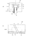
図1(A)は本発明の第1実施例にかかる蒸気タービンの軸シールユニットの円周方向に見た分割部の形態を示す図で、図13のY−Y線矢視図である。図1(B)は図1(A)におけるA視図である。
図1(A)、(B)において、1は複数のリーフ、2a,2bは軸方向に2分割されたリテーナで、前記各リーフ1はその外周部1bを該リテーナ2a,2bで図のように挟み込み、外周側に背部スペーサ(図示省略)を挿入して外周部が該リテーナ2a,2bに固定され、内周部は自由端1aとなっている。
該リーフ1の軸方向両側には、該リーフ1を通過する軸方向流体流を抑制するサイドリーフ(高圧側側板)3及びバックリーフ(低圧側側板)4が、該リーフ1を挟んだ形態で軸方向に対峙して設置されている。
5は前記軸シールユニット100を支持するシールハウジングである。
FIG. 1A is a diagram showing a configuration of a divided portion viewed in the circumferential direction of the shaft seal unit of the steam turbine according to the first embodiment of the present invention, and is a view taken along line YY in FIG. FIG. 1B is a view as viewed from A in FIG.
1 (A) and 1 (B), 1 is a plurality of leaves, 2a and 2b are retainers divided into two in the axial direction, and each
On both sides in the axial direction of the
A
そして、該軸シールユニット100は、前記のように、環状に形成されており、前記回転軸7の外周への組付け上、通常、周方向において、分割隙間6に示すように、2〜8分割されている。
The
本発明の第1実施例においては、軸シールユニット100は、回転軸7(図11参照)の円周方向において、分割することにより形成される複数の前記分割隙間6のそれぞれに対応する部位における前記サイドリーフ3と前記シールハウジング5との間の空間に、可撓性を有する板材10を挿入して、図1(B)のように、該板材10により前記分割隙間6を塞ぐ。
そして、前記板材10の一端部を、シールハウジング5の突出部5aに、スポット溶接Xすることにより固定する。溶接箇所がこの図(図1(B))のように、2箇所でも複数箇所でもよい。
In the first embodiment of the present invention, the
Then, one end of the
かかる第1実施例によれば、前記サイドリーフ3と前記シールハウジング5との間の空間に、可撓性を有する板材10を挿入したことにより、該板材10により前記分割隙間6を塞ぐことができ、該分割隙間6そのものへの圧力流体の流路を無くすことができて、これにより分割隙間6周辺の圧力分布の不連続の発生が回避される。
従って、前記のように分割隙間6周辺の圧力分布の不連続の発生が回避できて、リーフ1の浮上特性の低下を防止でき、回転軸7の回転数の上昇時における回転軸7外周とリーフ1との間に適正隙間が形成できて、高回転時におけるリーフ1と回転軸7外周との接触が回避され、リーフ1の磨耗やリーフ1先端の流体シール部のシール不良による流体洩れの発生を回避できる。
According to the first embodiment, by inserting the
Accordingly, the occurrence of discontinuity in the pressure distribution around the dividing
また、かかる第1実施例によれば、前記可撓性を有する板材10をサイドリーフ3とシールハウジング5との間の空間に挿入して、スポット溶接Xして空間に係止できることにより、分割隙間6周辺を塞いで該分割隙間6周辺の圧力分布の不連続の発生を防止することができるので、従来の機器を設けたままの状態で、板材10を挿入し、スポット溶接Xによって、確実に落下防止を行うことができる。
Further, according to the first embodiment, the
図2(A)は本発明の第2実施例にかかる蒸気タービンの軸シールユニットの円周方向に見た分割部の形態を示す図で、図13のY−Y線矢視図である。図2(B)は図2(A)におけるA矢視図である。
この第2実施例においては、前記第1実施例と同様に、回転軸7(図11参照)の円周方向において、分割することにより形成される複数の前記分割隙間6のそれぞれに対応する部位におけるサイドリーフ3とシールハウジング5との間の空間に、前記可撓性を有する板材10を挿入して、図2(B)のように、該板材10により前記分割隙間6を塞ぐ。
そして、前記板材10の下端の折返部10tを、シールハウジング5に明けた孔7aに挿入して、かしめ結合により固定する。
かしめ結合の折返部10tは、図2(B)のように、両端部の2個所でも、長さ方向全長にわたって形成しても良い。
かかる第2実施例においても、従来の機器を設けたままの状態で、孔7aとかしめ結合によって、板材10の落下防止を確実に行うことができる。
その他の構成は前記第1実施例(図1〜2)と同様であり、これと同一の部材は同一符号で示す。
FIG. 2A is a view showing the form of the divided portion viewed in the circumferential direction of the shaft seal unit of the steam turbine according to the second embodiment of the present invention, and is a view taken along the line YY in FIG. FIG. 2B is a view taken in the direction of arrow A in FIG.
In the second embodiment, as in the first embodiment, portions corresponding to each of the plurality of divided
And the folding | returning
As shown in FIG. 2B, the caulking-joined folded
Also in the second embodiment, it is possible to reliably prevent the
Other configurations are the same as those of the first embodiment (FIGS. 1-2), and the same members are denoted by the same reference numerals.
図3(A)は本発明の第3実施例にかかる蒸気タービンの軸シールユニットの円周方向に見た分割部の形態を示す図で、図13のY−Y線矢視図である。図4は図3(A)におけるA矢視図である。また、図5(A1)、(B1)、(C1)は、板材10の折り曲げ方法を示す平面図であり、図5(A2)、(B2)、(C2)は、図5(A1)、(B1)、(C1)におけるC矢視であり、折り曲げた結果の形状を示す。
この第3実施例においては、回転軸7(図11参照)の円周方向において、分割することにより形成される複数の前記分割隙間6のそれぞれに対応する部位におけるサイドリーフ3とシールハウジング5との間の空間に、前記可撓性を有する板材10を挿入する。
一方、シールハウジング5の板材10に対向する部位の上部に溝5aを形成し、前記板材10の上部を屈曲させて溝5aに係合する1箇所以上の係合部10a(例えば、図4のように2箇所)を設け、図4のように、前記板材10により前記分割隙間6を塞ぐ。
FIG. 3 (A) is a view showing the form of the divided portion viewed in the circumferential direction of the shaft seal unit of the steam turbine according to the third embodiment of the present invention, and is a view taken along the line YY in FIG. FIG. 4 is a view taken in the direction of arrow A in FIG. 5 (A1), (B1), and (C1) are plan views showing a bending method of the
In the third embodiment, in the circumferential direction of the rotating shaft 7 (see FIG. 11), the
On the other hand, a
また、前記板材10の折り曲げ方法は図5(A1)、(B1)、(C1)に示している。
図5(A1)は係合部10aを上縁部全体に設けて、2つ折りにする。図5(B1)は係合部10a、10aを上縁部の両側に設けて、2つ折りにする。図5(C1)は係合部10a、10aを上縁部全体に設けて、3つ折りにする。
その他の構成は前記第1実施例(図1〜2)と同様であり、これと同一の部材は同一符号で示す。
Moreover, the bending method of the said board |
In FIG. 5A1, the engaging
Other configurations are the same as those of the first embodiment (FIGS. 1-2), and the same members are denoted by the same reference numerals.
かかる第3実施例によれば、板材10の係止手段としてシールハウジング5に、溝5aの加工を施し、板材10をこの溝5aに挿入するのみで、他の構成部品は既存の部品を流用することができて、分割隙間6周辺を覆うことができる。
According to the third embodiment, the
図6は本発明の第4実施例にかかる蒸気タービンの軸シールユニットの円周方向に見た分割部の形態を示す図である。また、図7(A1)、(B1)、(C1)は、板材10の折り曲げ方法を示す平面図であり、図7(A2)は図7(A1)のE−E線断面図であり、図7(B2)、(C2)は、図7(B1)、(C1)におけるF矢視であり、折り曲げた結果の形状を示す。
この第4実施例においては、回転軸7(図11参照)の円周方向において、分割することにより形成される複数の前記分割隙間6のそれぞれに対応する部位におけるサイドリーフ3とシールハウジング5との間の空間に、前記可撓性を有する板材10を挿入する。
一方、シールハウジング5の板材10に対向する部位の、中間部に溝5bを形成し、前記板材10の中間部を屈曲させ屈曲部を、前記溝5bに係合する板材中間係合部10cを設け、図4と同様に、前記板材10により前記分割隙間6を塞ぐ。
FIG. 6 is a diagram showing the form of the divided portion viewed in the circumferential direction of the shaft seal unit of the steam turbine according to the fourth embodiment of the present invention. 7 (A1), (B1), and (C1) are plan views showing a bending method of the
In the fourth embodiment, in the circumferential direction of the rotating shaft 7 (see FIG. 11), the
On the other hand, a
また、前記板材10の折り曲げ方法は図7(A1)、(B1)、(C1)に示している。
図7(A1)は係合部の中央部10cを屈曲させ該屈曲部を前記溝5bに挿入する。図7(B1)は係合部10c、10cを180°に折り曲げて前記溝5bに挿入する。図7(C1)は係合部10c、10cを2つに折り曲げて前記溝5bに挿入する。
その他の構成は前記第1実施例(図1〜2)と同様であり、これと同一の部材は同一符号で示す。
Moreover, the bending method of the said board |
In FIG. 7A1, the
Other configurations are the same as those of the first embodiment (FIGS. 1-2), and the same members are denoted by the same reference numerals.
かかる第4実施例によれば、板材10の係止手段として、シールハウジング5の中間部に溝5bの加工を施し、板材10をこの溝5bに挿入するのみで、他の構成部品は既存の部品を流用することができて、分割隙間6周辺を覆うことができる。
According to the fourth embodiment, as a means for locking the
図8は本発明の第5実施例にかかる蒸気タービンの軸シールユニットの円周方向に見た分割部の形態を示す図である(構成自体は図6と同様である)。また図9は図8のZ矢視図である。
この第5実施例においては、前記第4実施例と同様な構成であるが、図9に示すように、該板材10の回転軸7の周方向に沿う、幅の適当部分に前記溝10d及び板材中間係合部5sを構成して組み付ける。5zはシールハウジング5の分割部である。
つまり板材10が前記分割隙間6を塞ぐことができれば、前記溝10d及び板材中間係合部5sを設ける周方向の位置は、分割隙間6の周方向の位置に非対称でもよい。これによって、シールハウジング5に前記溝10dを加工する際には、片側にのみ前記溝10dを設けるのみで良くなることから、加工工程を減らすことが可能となる。
その他の構成は前記第1実施例(図1〜2)と同様であり、これと同一の部材は同一符号で示す。
FIG. 8 is a view showing the configuration of the divided portion viewed in the circumferential direction of the shaft seal unit of the steam turbine according to the fifth embodiment of the present invention (the configuration itself is the same as that of FIG. 6). FIG. 9 is a view taken in the direction of arrow Z in FIG.
In the fifth embodiment, the configuration is the same as that of the fourth embodiment. However, as shown in FIG. 9, the
That is, as long as the
Other configurations are the same as those of the first embodiment (FIGS. 1-2), and the same members are denoted by the same reference numerals.
図10(A)は本発明の第6実施例にかかる蒸気タービンの軸シールユニットの円周方向に見た分割部の形態を示す図で、図13のY−Y線矢視図である。図10(B)は図10(A)におけるA矢視図である。
この第6実施例においては、回転軸7(図11参照)の円周方向において、分割することにより形成される複数の前記分割隙間6のそれぞれに対応する部位におけるサイドリーフ3とシールハウジング5との間の空間に、前記可撓性を有する板材10を挿入する。
そして、前記リーフ1の上部リテーナ2aの下部面と前記シールハウジング5の対応面との間に形成された支持面2cに、前記板材10の上部を屈曲させて前記支持面2cに係合する板材上部支持部10dを挟み込み、該板材10を支持する。
FIG. 10 (A) is a view showing the form of the divided portion viewed in the circumferential direction of the shaft seal unit of the steam turbine according to the sixth embodiment of the present invention, and is a view taken along the line YY in FIG. FIG. 10B is a view as seen from an arrow A in FIG.
In the sixth embodiment, in the circumferential direction of the rotating shaft 7 (see FIG. 11), the
Then, a plate member that is engaged with the
かかる第6実施例によれば、板材10の係止手段として、リーフ1の上部リテーナ2aの下部面と前記シールハウジング5の対応面との間に形成された支持面2cに、前記板材10の上部を屈曲させて前記支持面2cに係合する板材上部支持部10dを挟み込むので、
リーフ1の上部リテーナ2aに支持面2cの加工を施し、板材10をこの支持面2cに挿入するのみで、他の構成部品は既存の部品を流用することができて、分割隙間6周辺を確実に覆うことができる。
According to the sixth embodiment, as a means for locking the
By simply processing the
本発明は、前記蒸気タービンのほか、ガスタービン、軸流圧縮機等の、回転軸外周とケース部材との間の隙間を軸方向に沿って流れる流体のシールを行なうようにした回転機械の軸シール装置全般に適用できる。 In addition to the steam turbine, the present invention provides a shaft for a rotary machine, such as a gas turbine, an axial compressor, etc., that seals fluid flowing along the axial direction in the gap between the outer periphery of the rotary shaft and the case member. Applicable to all sealing devices.
本発明によれば、軸シールユニットの分割隙間を通っての流体洩れを抑制して、かかる流体洩れによるリーフの浮上特性の低下及びこれに伴うリーフの磨耗やリーフ先端の流体シール部のシール不良による流体洩れの発生を回避した回転機械の軸シール装置を提供できる。 According to the present invention, fluid leakage through the division gap of the shaft seal unit is suppressed, and the floating characteristics of the leaf due to such fluid leakage are reduced, and the resulting leaf wear and the seal failure of the fluid seal portion at the tip of the leaf It is possible to provide a shaft seal device for a rotating machine that avoids the occurrence of fluid leakage due to the above.
100 軸シールユニット
1 リーフ
1a 自由端
2 サイドリーフ(高圧側側板)
2a リテーナ
2b リテーナ
2c 支持面
3 バックリーフ(低圧側側板)
5 シールハウジング
5a 溝
5b 溝
6 分割隙間
7 回転軸
7a 孔
10 板材
10a 係合部
10d 溝
X スポット溶接
100
5
Claims (8)
前記軸シールユニットは、前記回転軸の周方向において分割することにより形成される複数の分割隙間のそれぞれに対応する部位における前記高圧側側板と前記ケース部材との間の空間に、可撓性を有する板材を挿入して該板材により前記分割隙間を塞ぐとともに、前記板材を前記空間に係止する係止手段を設けたことを特徴とする回転機械の軸シール装置。 A shaft sealing device for a rotating machine that seals a fluid flowing along an axial direction between the outer periphery of a rotating shaft of a rotating machine and a case member, and a large number of thin plate leaves along the circumferential direction of the rotating shaft And a fluid seal portion is formed between the free end and the outer periphery of the rotating shaft with the outer peripheral portion of the leaf fixed to the case member and the inner peripheral portion as a free end, and both axial sides of the leaf A shaft seal unit is provided in which a high-pressure side plate (side leaf) and a low-pressure side plate (back leaf) that suppress the axial fluid flow passing through the leaf are installed facing each other across the leaf. In the shaft seal device of a rotating machine,
The shaft seal unit is flexible in a space between the high-pressure side plate and the case member in a portion corresponding to each of a plurality of divided gaps formed by dividing in the circumferential direction of the rotating shaft. A shaft seal device for a rotary machine, comprising a plate member inserted therein to close the dividing gap with the plate member and a locking means for locking the plate material in the space.
Priority Applications (1)
| Application Number | Priority Date | Filing Date | Title |
|---|---|---|---|
| JP2008132137A JP5118552B2 (en) | 2008-05-20 | 2008-05-20 | Shaft seal device for rotating machinery |
Applications Claiming Priority (1)
| Application Number | Priority Date | Filing Date | Title |
|---|---|---|---|
| JP2008132137A JP5118552B2 (en) | 2008-05-20 | 2008-05-20 | Shaft seal device for rotating machinery |
Publications (2)
| Publication Number | Publication Date |
|---|---|
| JP2009281437A JP2009281437A (en) | 2009-12-03 |
| JP5118552B2 true JP5118552B2 (en) | 2013-01-16 |
Family
ID=41452108
Family Applications (1)
| Application Number | Title | Priority Date | Filing Date |
|---|---|---|---|
| JP2008132137A Active JP5118552B2 (en) | 2008-05-20 | 2008-05-20 | Shaft seal device for rotating machinery |
Country Status (1)
| Country | Link |
|---|---|
| JP (1) | JP5118552B2 (en) |
Cited By (1)
| Publication number | Priority date | Publication date | Assignee | Title |
|---|---|---|---|---|
| US11614035B2 (en) | 2018-02-19 | 2023-03-28 | Mitsubishi Heavy Industries, Ltd. | Seal segment and rotating machine |
Families Citing this family (9)
| Publication number | Priority date | Publication date | Assignee | Title |
|---|---|---|---|---|
| US8413992B2 (en) | 2009-06-16 | 2013-04-09 | Mitsubishi Heavy Industries, Ltd. | Shaft seal and rotary machine with same |
| JP5398651B2 (en) | 2010-06-24 | 2014-01-29 | 三菱重工業株式会社 | Shaft sealing mechanism and rotating machine equipped with the same |
| JP5804893B2 (en) * | 2011-10-26 | 2015-11-04 | 三菱重工業株式会社 | Shaft seal device and rotary machine equipped with the same |
| JP5931450B2 (en) * | 2012-01-13 | 2016-06-08 | 三菱重工業株式会社 | Shaft seal device and rotary machine equipped with the same |
| JP6012505B2 (en) * | 2013-02-22 | 2016-10-25 | 三菱重工業株式会社 | Shaft seal device and rotary machine |
| DE102013219832B3 (en) * | 2013-09-30 | 2015-03-12 | MTU Aero Engines AG | Brush seal for a turbo machine |
| JP6675262B2 (en) | 2016-05-09 | 2020-04-01 | 三菱日立パワーシステムズ株式会社 | Seal segment and rotating machine |
| CN108952826B (en) * | 2018-06-06 | 2020-12-18 | 中国航发沈阳发动机研究所 | Air pressure elastic sealing device and gas turbine engine |
| JP7777464B2 (en) * | 2022-02-16 | 2025-11-28 | 三菱重工業株式会社 | Seal devices and rotating machines |
Family Cites Families (5)
| Publication number | Priority date | Publication date | Assignee | Title |
|---|---|---|---|---|
| JP3968620B2 (en) * | 1999-02-05 | 2007-08-29 | イーグル・エンジニアリング・エアロスペース株式会社 | Brush type sealing device |
| JP3616016B2 (en) * | 2000-04-28 | 2005-02-02 | 三菱重工業株式会社 | Shaft seal mechanism and gas turbine |
| JP3691000B2 (en) * | 2001-06-20 | 2005-08-31 | 三菱重工業株式会社 | Shaft seal mechanism and gas turbine |
| JP3593082B2 (en) * | 2001-10-09 | 2004-11-24 | 三菱重工業株式会社 | Shaft seal mechanism and turbine |
| JP3950455B2 (en) * | 2004-04-20 | 2007-08-01 | 三菱重工業株式会社 | Shaft sealing member, shaft sealing mechanism and large fluid machine |
-
2008
- 2008-05-20 JP JP2008132137A patent/JP5118552B2/en active Active
Cited By (1)
| Publication number | Priority date | Publication date | Assignee | Title |
|---|---|---|---|---|
| US11614035B2 (en) | 2018-02-19 | 2023-03-28 | Mitsubishi Heavy Industries, Ltd. | Seal segment and rotating machine |
Also Published As
| Publication number | Publication date |
|---|---|
| JP2009281437A (en) | 2009-12-03 |
Similar Documents
| Publication | Publication Date | Title |
|---|---|---|
| JP5118552B2 (en) | Shaft seal device for rotating machinery | |
| JP5830247B2 (en) | Method and apparatus for labyrinth seal packing ring | |
| US9074486B2 (en) | Method and apparatus for labyrinth seal packing ring | |
| US8628092B2 (en) | Method and apparatus for packing rings | |
| CN104696022B (en) | Seal assemblies and corresponding turbine | |
| CN102362107B (en) | Shaft seal and rotary machine with same | |
| US20070102886A1 (en) | Shaft sealing mechanism | |
| KR20070121556A (en) | Seal Assembly and Rotator for Rotator | |
| US9677669B2 (en) | Shaft seal device and rotary machine | |
| WO2014103446A1 (en) | Segmented seal | |
| US9103222B2 (en) | Turbine engine variable area vane with feather seal | |
| EP2803883B1 (en) | Shaft seal device and rotary machine with same | |
| EP3032149B1 (en) | Sealing device, rotating machine, and method for manufacturing sealing device | |
| JP2003004145A (en) | Seal for rotary shaft | |
| US8459653B2 (en) | Seal assembly segment joints | |
| JP3950455B2 (en) | Shaft sealing member, shaft sealing mechanism and large fluid machine | |
| CN1475657A (en) | Steam turbine gland horizontal joint seal and method of forming same | |
| JP5449976B2 (en) | Shaft seal device, turbine device, and shaft seal device gap adjusting method | |
| US6997677B2 (en) | Method and apparatus for rotating machine main fit seal | |
| JP6358976B2 (en) | Turbine sealing device and turbine, and thin plate for sealing device | |
| JP4625438B2 (en) | Shaft seal device for rotating machinery | |
| CN112771248B (en) | Turbine stator, steam turbine and partition plate | |
| EP2520834A1 (en) | Spring seal assembly and method of sealing a gap | |
| JP3917997B2 (en) | Shaft seal mechanism | |
| JP7064071B2 (en) | Shaft sealing device and rotary machine equipped with this shaft sealing device |
Legal Events
| Date | Code | Title | Description |
|---|---|---|---|
| A621 | Written request for application examination |
Free format text: JAPANESE INTERMEDIATE CODE: A621 Effective date: 20110201 |
|
| A977 | Report on retrieval |
Free format text: JAPANESE INTERMEDIATE CODE: A971007 Effective date: 20120328 |
|
| TRDD | Decision of grant or rejection written | ||
| A01 | Written decision to grant a patent or to grant a registration (utility model) |
Free format text: JAPANESE INTERMEDIATE CODE: A01 Effective date: 20120925 |
|
| A01 | Written decision to grant a patent or to grant a registration (utility model) |
Free format text: JAPANESE INTERMEDIATE CODE: A01 |
|
| A61 | First payment of annual fees (during grant procedure) |
Free format text: JAPANESE INTERMEDIATE CODE: A61 Effective date: 20121019 |
|
| R151 | Written notification of patent or utility model registration |
Ref document number: 5118552 Country of ref document: JP Free format text: JAPANESE INTERMEDIATE CODE: R151 |
|
| FPAY | Renewal fee payment (event date is renewal date of database) |
Free format text: PAYMENT UNTIL: 20151026 Year of fee payment: 3 |
|
| R250 | Receipt of annual fees |
Free format text: JAPANESE INTERMEDIATE CODE: R250 |