JP5118348B2 - Work transfer device - Google Patents
Work transfer device Download PDFInfo
- Publication number
- JP5118348B2 JP5118348B2 JP2007001337A JP2007001337A JP5118348B2 JP 5118348 B2 JP5118348 B2 JP 5118348B2 JP 2007001337 A JP2007001337 A JP 2007001337A JP 2007001337 A JP2007001337 A JP 2007001337A JP 5118348 B2 JP5118348 B2 JP 5118348B2
- Authority
- JP
- Japan
- Prior art keywords
- conveyor
- path length
- workpiece
- forging
- along
- Prior art date
- Legal status (The legal status is an assumption and is not a legal conclusion. Google has not performed a legal analysis and makes no representation as to the accuracy of the status listed.)
- Expired - Fee Related
Links
Images


Description
本発明は、異種のワークを高速且つ自動的に搬送することが可能なワーク搬送路長切換機構を備えるワーク搬送装置に関する。
The present invention relates to a workpiece transfer apparatus including a workpiece transfer path length switching mechanism capable of automatically transferring different types of workpieces at high speed.
例えば、エンジン等のクランクシャフトや歯車等の部品は、円柱状のビレットに対して複数の鍛造成形工程を遂行することによって製造されている。この場合、前記鍛造成形する際、金型内へのビレットの配置形態によって、いわゆる「縦打ち」といわゆる「横打ち」とに大別される。 For example, components such as crankshafts and gears for engines and the like are manufactured by performing a plurality of forging processes on a cylindrical billet. In this case, when the forging is performed, the billet is roughly classified into so-called “vertical strike” and so-called “horizontal strike” depending on the arrangement of billets in the mold.
前記「縦打ち」とは、ビレットの一端面が底面となるように下型のキャビティ内に配置されて鍛造成形される成形方法をいい、この「縦打ち」によって、例えば、歯車が鍛造成形される。 The term “vertical punching” refers to a molding method in which one end surface of the billet is placed in the cavity of the lower mold so that the bottom surface is the bottom surface, and forging is performed. The
一方、前記「横打ち」とは、ビレットの軸線方向に沿った両端面が両側面となるように下型のキャビティ内に配置されて鍛造成形される成形方法をいい、この「横打ち」によって、例えば、クランクシャフトが鍛造成形される。 On the other hand, the above-mentioned “horizontal strike” refers to a molding method in which both end faces along the billet's axial direction are both side faces and are forged and placed in the cavity of the lower mold. For example, a crankshaft is forged.
この種の鍛造成形装置に関し、例えば、特許文献1には、1台の鍛造プレス装置によって「縦打ち」と「横打ち」とを行うことによってそれぞれ逆の部位から排出される成形品とピアス、又は成形品とバリを、2系統の各コンベアを成形品払い出し用とスクラップ払い出し用に適宜選択的に入れ換えて使用することによって、成形品とスクラップを自動的に払い出すことができる鍛造設備の払い出し装置と、その鍛造設備の払い出し装置に使用されるコンベアとがそれぞれ開示されている。 With regard to this type of forging apparatus, for example, Patent Document 1 discloses that a molded product and a pierced article that are discharged from opposite parts by performing “vertical strike” and “horizontal strike” by one forging press apparatus, Alternatively, forging equipment that can automatically dispense molded products and scrap by selectively switching between two conveyors for molding products and burrs as needed for molded product delivery and scrap delivery. An apparatus and a conveyor used in a forging equipment dispensing apparatus are disclosed.
しかしながら、前記特許文献1に開示されたコンベアでは、横打ち製品であるクランクシャフトを搬送するためのクランクシャフト搬出用コンベアと、縦打ち製品である歯車を搬送するための歯車搬出用コンベアとが鍛造プレス装置に対してそれぞれ別個に接合されているため、各コンベアの設置スペースが増大すると共に、ワークの搬送速度が低下し生産効率が低下するという問題がある。 However, in the conveyor disclosed in Patent Document 1, a crankshaft carrying-out conveyor for conveying a crankshaft that is a laterally punched product and a gear-loading conveyor for conveying a gear that is a vertically-placed product are forged. Since they are separately joined to the press device, there is a problem that the installation space for each conveyor increases, and the work conveyance speed decreases and the production efficiency decreases.
本発明は、前記の問題に鑑みてなされたものであり、異種のワークを1系統のコンベアによって自動的に且つ高速で搬送することが可能なワーク搬送路長切換機構を備えるワーク搬送装置を提供することを目的とする。
The present invention has been made in view of the above problems, and provides a workpiece transfer device including a workpiece transfer path length switching mechanism that can automatically transfer different types of workpieces at a high speed by a single system conveyor. The purpose is to do.
前記の目的を達成するために、本発明は、ワークが載置される搬送路がローラによって回転自在に設けられたコンベアと、
前記コンベアのフレームに固定されたリニアアクチュエータと、
前記リニアアクチュエータの駆動作用下に、略水平方向に沿って前記ローラと一体的に変位自在に設けられたスライダと、
を備え、
異種のワークに対応して前記コンベアに沿って搬送されるワークの搬送路長を、短縮された第1搬送路長と伸長された第2搬送路長との間で切り換えることを特徴とする。
In order to achieve the above object, the present invention provides a conveyor in which a conveyance path on which a workpiece is placed is rotatably provided by a roller,
A linear actuator fixed to the conveyor frame;
A slider provided so as to be displaceable integrally with the roller along a substantially horizontal direction under the driving action of the linear actuator;
With
The conveyance path length of the workpiece conveyed along the conveyor corresponding to different kinds of workpieces is switched between the shortened first conveyance path length and the elongated second conveyance path length.
本発明によれば、リニアアクチュエータの駆動作用下にスライダ及びローラが水平方向に沿って一体的に変位し、コンベアの搬送路長が伸縮されることにより、異種のワークに対応して前記コンベアに沿って搬送されるワークの搬送路長を、短縮された第1搬送路長と伸長された第2搬送路長との間で切り換えられる。 According to the present invention, the slider and the roller are integrally displaced along the horizontal direction under the driving action of the linear actuator, and the conveyor path length of the conveyor is expanded and contracted. The transport path length of the workpiece transported along is switched between the shortened first transport path length and the extended second transport path length.
この場合、複数の上型及び下型により同時に多工程の成形を遂行し且つワークに対応して前記複数の上型及び下型が一体的に交換可能な単一の鍛造成形装置に接続された1系統のコンベアによって構成され、例えば、鍛造成形されるワークがクランクシャフトからギヤへと変更されて前記ワークに対応する上型及び下型が一体的に交換された場合であっても、ワーク搬送路長切換機構を付勢して、鍛造成形された成形品に対し好適な搬送路長に迅速且つ簡便に切り換えることができる。 In this case, a plurality of upper molds and lower molds are simultaneously subjected to multi-step molding, and the plurality of upper molds and lower molds are connected to a single forging apparatus that can be replaced integrally corresponding to the workpiece. Consists of a single conveyor system, for example, even when the workpiece to be forged is changed from a crankshaft to a gear and the upper and lower molds corresponding to the workpiece are replaced together, By energizing the path length switching mechanism, it is possible to quickly and easily switch to a suitable transport path length for a forged molded product.
本発明では、異種のワークを1系統からなるコンベアによって自動的に且つ高速で搬送することができる。従って、本発明では、従来技術のように多種類の複数のコンベアを設けることが不要となり、コンベアの設置スペースを削減して設置スペースの有効利用を図ることができると共に、従来技術と比較してワークの搬送速度を向上させることができる。 In the present invention, different kinds of workpieces can be automatically and at high speed conveyed by a conveyor consisting of one system. Therefore, in the present invention, it is not necessary to provide a plurality of types of conveyors as in the prior art, and the installation space of the conveyor can be reduced and the installation space can be effectively used. The work conveyance speed can be improved.
本発明に係るワーク搬送路長切換機構を備えるワーク搬送装置について好適な実施の形態を挙げ、添付の図面を参照しながら以下詳細に説明する。
A preferred embodiment of a workpiece transfer apparatus including a workpiece transfer path length switching mechanism according to the present invention will be described in detail below with reference to the accompanying drawings.
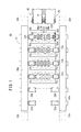
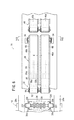
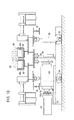
図1において、参照符号10は、本発明の実施の形態に係るワーク搬送路長切換機構が組み込まれたワーク搬送装置を備えた鍛造成形システムを示す。この鍛造成形システム10は、第1〜第5工程が連続して遂行される第1〜第4鍛造金型12a〜12dを有する鍛造成形装置14と、前記鍛造成形装置14に近接配置され該鍛造成形装置14によって鍛造成形された成形品及びバリをそれぞれ搬送するワーク搬送装置16とから構成される。
In FIG. 1,
この場合、前記鍛造成形装置14は、前記第1〜第4鍛造金型12a〜12dからなる複数の上型及び下型により同時に多工程の型打ちを行うことができる多工程鍛造成形プレスであって、型打ち時における上下の金型の位置決め精度を保持しながら、第1〜第4鍛造金型12a〜12dからなる上型及び下型全体を図示しない上ダイホルダ及び下ダイホルダと一体的に交換可能に設けられている。
In this case, the
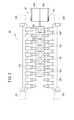
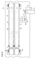
なお、図1では、いわゆる「横打ち」によってクランクシャフト24を鍛造成形する第1〜第4鍛造金型12a〜12dが下ダイホルダ上に配置された状態が示されており、一方、図2は、例えば、「縦打ち」によってギヤ25a、25bを2個同時に鍛造成形することが可能な第1〜第4鍛造金型18a〜18dに交換された場合を示している。
FIG. 1 shows a state in which the first to fourth forging dies 12a to 12d for forging the
また、図1に示されるように、前記第1〜第4鍛造金型12a〜12dは直線状に配列された単一の上型(図示せず)と単一の下型とによって構成されており、前記上型は、図示しないプレスラムに連結された上ダイホルダ(図示せず)に固定されて一体的に昇降自在に設けられ、前記下型は、図示しないクランプ機構を介して下ダイホルダに固定される。 Further, as shown in FIG. 1, the first to fourth forging dies 12a to 12d are constituted by a single upper die (not shown) and a single lower die arranged in a straight line. The upper die is fixed to an upper die holder (not shown) connected to a press ram (not shown) and is provided so as to be movable up and down integrally. The lower die is fixed to the lower die holder via a clamping mechanism (not shown). Is done.
さらに、前記第1〜第4鍛造金型12a〜12dの配列方向の両側には、該下型から所定距離離間しワークを各成形工程に対して連続して自動送りするための中空でレール状の一対のフィードバー20a、20bが前記下型を間にした水平方向に沿って対向配置されている。
Further, on both sides in the arrangement direction of the first to fourth forging dies 12a to 12d, a hollow, rail-like shape for separating the predetermined distance from the lower die and automatically feeding the workpiece continuously to each forming step. A pair of
前記一対のフィードバー20a、20bは、図示しない装置本体に固定されたトランスファ機構によって、第1〜第4鍛造金型12a〜12dの配列方向に沿ったX軸方向と、前記X軸方向と直交するY軸方向と、前記第1〜第4鍛造金型12a〜12dの上下方向(高さ方向)に沿ったZ軸方向とからなる3軸方向に沿ってそれぞれ略同時に移動可能に設けられる。
The pair of
前記一対のフィードバー20a、20bには、各工程においてワークを把持するための複数のクランプ爪22a〜22fが対向配置されると共に、前記一対のクランプ爪22c〜22fが第1〜第4鍛造金型12a〜12dに対応する位置にそれぞれ離間して複数個並列状に配置される。
A plurality of
また、一方のフィードバー20a側のクランプ爪22a〜22fには、ワークが把持されて該ワークによってクランプ爪22a〜22fが押圧されることによりワークのクランプ状態を検知する図示しない検出センサがそれぞれ付設されている。なお、前記検出センサは、図示しないばね部材のばね力によって付勢されたクランプ爪22a〜22fが前記ばね部材のばね力に抗して押圧されることにより、ワークが確実にクランプされたことを検知するクランプ検出信号を図示しない外部制御装置に向かって導出する近接センサによって構成されるとよい。
Each of the
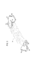
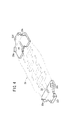
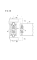
さらに、第4鍛造金型12dに対応する位置に所定距離離間して設けられた相互に対向する一対のクランプ爪22fには、図3に示されるように、成形品であるクランクシャフト24の両端部をそれぞれ把持する凹部26が形成されると共に、図4に示されるように、前記成形品に付着して打ち抜かれたバリ28を把持するための略ハの字形状からなる一対の突起部30a、30bがその上面に膨出形成される。
Furthermore, as shown in FIG. 3, both ends of the
なお、相互に対向する一方のクランプ爪22a〜22fと他方のクランプ爪22a〜22fは、クランクシャフト24の両端部の形状がそれぞれ異なるため、具体的には爪形状が僅かに相違するが、図面では便宜上同一形状に描写されている。また、成形品をギヤ25a、25bとした場合、前記ギヤ25a、25bを把持するクランプ爪の形状がクランクシャフト24と相違することは勿論である(図1及び図2比較参照)。
In addition, since one clamp nail |
前記一対のフィードバー20a、20bの両端部は、それぞれトランスファ機構のフィードバー着脱部32a、32bによって挟持され、後述するように、前記フィードバー着脱部32a、32bを介してトランスファ機構に対して前記一対のフィードバー20a、20bが着脱自在且つ交換可能に設けられている。この場合、トランスファ機構のフィードバー着脱部32a、32bとフィードバー20a、20bの両端部には、図示しない凹部と凸部とからなる位置決め機構が設けられ、前記位置決め機構を介して同軸状に精度よく連結される。
Both ends of the pair of
金型の交換作業では、前記フィードバー20a、20bがダイセット(金型を含む)と一体的に交換される。すなわち、トランスファ機構を3軸方向に付勢してフィードバー着脱部32a、32bをフィードバー20a、20bの両端部からそれぞれ離間させることにより、フィードバー20a、20bをトランスファ機構から取り外し、前記取り外されたフィードバー20a、20bを下ダイホルダ上に設けられた図示しないフィードバー支持部に支持することにより、上下型及び上下ダイセットと一体的に前記フィードバー20a、20bを鍛造成形装置14の外部に引き出して交換することができる。
In the mold exchanging operation, the
ワーク搬送装置16は、鍛造成形装置14に近接して配置され第1回転駆動源34の駆動作用下に所定距離離間する一組のローラがそれぞれ回転し前記ローラの回転運動が伝達されたベルト体が回転することにより成形品(クランクシャフト24、ギヤ25a、25b)又はバリ28を水平方向に沿って搬送する第1コンベア36と、前記第1コンベア36に連続し且つ同軸で直線状に配置され第2回転駆動源38の駆動作用下に所定距離離間する一組のローラがそれぞれ回転し前記ローラの回転運動が伝達されたベルト体が回転することにより成形品のみを水平方向に沿って搬送する第2コンベア40とを有する。
The
なお、前記第2コンベア40の下流側には、図示しないスラットコンベアが設けられ、第2コンベア40によって搬送された成形品が前記スラットコンベアを介して次工程に移送される。
A slat conveyor (not shown) is provided on the downstream side of the
前記第1コンベア36及び第2コンベア40には、それぞれ軸線方向に沿った一端部(搬送方向に沿った終端部)を支点として該第1コンベア36及び第2コンベア40の他端部(搬送方向に沿った始点部)を円弧状に所定角度だけ回動させる第1回動機構42及び第2回動機構44と(図8〜図11参照)、前記第1コンベア36及び第2コンベア40をそれぞれ構成する並列的に配置された第1搬送路46aと第2搬送路46bとの離間距離X(搬送方向と直交するコンベア幅)を調整する第1コンベア幅調整機構48a及び第2コンベア幅調整機構48bと(図12及び図13参照)、前記第1コンベア36にのみ設けられ、鍛造成形装置14に近接する第1コンベア36の軸線方向に沿った全長を異種のワークに対応して、短縮された第1コンベア長(第1搬送路長)と伸長された第2コンベア長(第2搬送路長)とを相互に切り換えるコンベア長切換機構50(図14参照)とを有する。
The
このコンベア長切換機構50は、ワーク搬送路長切換機構として機能するものであり、異種のワークとしては、横打ち製品であるクランクシャフト24をその一例とし、縦打ち製品であるギヤ25a、25bをその一例として説明しているが、前記クランクシャフト24、ギヤ25a、25bに限定されるものではない。
The conveyor
第1コンベア36に設けられた第1回動機構42は、主として、金型交換の際に金型との接触を防止するために設けられたものであり、図8に示されるように、ピボット47を揺動支点として揺動自在に設けられたトラニオン形の第1シリンダ52を有し、前記第1シリンダ52を駆動させることにより、搬送方向に沿ったフレーム49の終端部側に設けられたヒンジ部51をその回動支点として第1コンベア36が略水平状態から上方に向かって所定角度だけ回動(傾動)する。
The
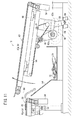
第2コンベア40に設けられた第2回動機構44は、成形品であるクランクシャフト24を水平方向に沿って搬送した後、続いて搬送されるバリ28を下方のバリシュート54側に導入するために設けられたものである。
The second
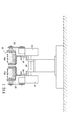
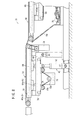
第2回動機構44は、図9〜図11に示されるように、フレーム56に固定された回転駆動源58と、前記回転駆動源58の駆動軸に連結された駆動プーリ62aと従動プーリ62bとの間に懸架されたチェーン64と、前記従動プーリ62bの回転中心から偏心して軸支され該従動プーリ62bの回転運動が伝達される偏心カム60と、前記偏心カム60の偏位作用下に上下方向に沿って所定角度揺動するコンベアベッド66と、前記コンベアベッド66の下部であって搬送方向と直交する両側にそれぞれ配置され前記コンベアベッド66が所定角度傾動する際に補助的に作動する一組の第2シリンダ68とを有する。なお、前記第2シリンダ68は、ピボット69を揺動支点として揺動自在に設けられたトラニオン形シリンダによって構成される。
As shown in FIGS. 9 to 11, the
第1コンベア幅調整機構48aは、図示しない第2コンベア幅調整機構48bと同一構成からなるため、第1コンベア幅調整機構48aについて詳細に説明し、第2コンベア幅調整機構48bの説明を省略する。
Since the first conveyor
前記第1コンベア幅調整機構48aは、図12に示されるように、回転駆動源70と、前記回転駆動源70の駆動軸に連結された第1プーリ72aと第2プーリ72bとの間に懸架され前記回転駆動源70の駆動力を前記第2プーリ72bに伝達するチェーン74と、前記第2プーリ72bに軸着されて該第2プーリ72bと一体的に回転運動が伝達されると共に第1及び第2ベアリングブロック76a、76bを介して回転自在に軸支される回転シャフト78と、前記回転シャフト78の両端部側に所定間隔離間して設けられねじ切り方向が互いに逆方向となるように形成された第1雄ねじ部80a及び第2雄ねじ部80bと、前記回転シャフト78の第1雄ねじ部80a及び第2雄ねじ部80bにそれぞれ螺合する第1雌ねじ部及び第2雌ねじ部を有する一対のブラケット82a、82bと、前記一対のブラケット82a、82bにそれぞれ連結されフレーム56に固定された一対のガイドレール84a、84b(図13参照)に沿って接近又は離間可能に設けられたコンベアベッド66とを含む。
As shown in FIG. 12, the first conveyor
この場合、前記回転駆動源70の駆動力がチェーン74及び第2プーリ72bを介して前記回転シャフト78に伝達され該回転シャフト78が所定方向に回動することにより、互いに逆ねじに形成された第1雄ねじ部80a及び第2雄ねじ部80bを介して一対のブラケット82a、82bが水平方向に沿った相互に接近する方向又は離間する方向(搬送方向と直交する方向)に変位し、前記ブラケット82a、82bにそれぞれ連結されたコンベアベッド66を介して第1コンベア36を構成する第1搬送路46aと第2搬送路46bとの離間距離(X)がワークに対応して適宜設定される。
In this case, the driving force of the rotation drive
この場合、第1搬送路46aと第2搬送路46bとの離間距離(X)を調整して適宜選択することによって、例えば、種々のエンジンに組み込まれる各種クランクシャフト24の全長に対応した所望のコンベア幅に設定することができる。なお、成形品をギヤ25a、25bとした場合には、前記第1搬送路46aと第2搬送路46bとの離間距離(X)が略零に設定され(図2参照)、前記ギヤ25a、25bを第1及び第2搬送路46a、46b上に載置して好適に搬送される。
In this case, by adjusting and appropriately selecting the separation distance (X) between the
コンベア長切換機構50は、図14及び図6に示されるように、第1コンベア36の上部側フレームに固定され、リニアアクチュエータとして機能する扁平な第3シリンダ86と、前記第3シリンダ86のピストンロッド86aが進退自在に挿通する貫通孔が形成されたブロック体からなるヨーク88と、前記第3シリンダ86のピストンロッド86aを間にしてその両側に略平行に配置された一組のガイドロッド90a、90bと、前記第3シリンダ86のピストンロッド86a及び前記ガイドロッド90a、90bの一端部に連結されたスライダ92と、前記スライダ92の両側に回転自在に軸着されると共に、前記スライダ92と一体的に水平方向に沿って移動するベルト回転用ローラ94とを有する。
As shown in FIGS. 14 and 6 , the conveyor
また、コンベア長切換機構50は、前記第3シリンダ86に近接配置され、ピストンロッド96aが下方側に向かって延在するように設けられた第4シリンダ96を有する。この第4シリンダ96は、コンベア長が変更されたときに複数のプーリ72間を懸架するチェーン74のテンションを適度に調整するためのものであり、例えば、コンベア長が短縮されてチェーン74が弛み状態のときにピストンロッド96aが下方側に伸長して前記チェーン74のテンションを適度に調整すると共に、コンベア長が伸長されたときにピストンロッド96aが上方側に伸長してチェーン74のテンションを適度に調整する機能を有する。
The conveyor
なお、図14に示されるように、前記第3シリンダ86の駆動作用下にベルト回転用ローラ94及びスライダ92を水平方向に沿って伸縮させた場合であっても、鍛造成形装置14を構成するダイセット97の端面97aの位置は、変化することがなく一定であり、また、このダイセット97の端面97aの位置は、クランクシャフト24又はギヤ25a、25b等の異種のワークに対応して金型が一体的に交換された場合であっても同一である。
As shown in FIG. 14, the forging
本発明の実施の形態に係るコンベア長切換機構50が組み込まれたワーク搬送装置16を備えた鍛造成形システム10は、基本的には以上のように構成されるものであり、次にその動作並びに作用効果について説明する。
The forging and forming
図示しないワーク供給ステーションからワーク(円柱状のビレット)を順次搬送し、供給されたワークを保持する第1工程と、前記ワークを圧潰する第2工程と、第2工程で潰されたワークを成形品の概略形状とする荒打ちからなる第3工程と、ワークの形状を成形品の形状に仕上げる第4工程と、前記成形品に付着したバリ28を射抜く第5工程とがそれぞれ連続してなされることにより、例えば、クランクシャフト24の成形品が得られる。
A workpiece (columnar billet) is sequentially conveyed from a workpiece supply station (not shown), a first step for holding the supplied workpiece, a second step for crushing the workpiece, and a workpiece crushed in the second step are formed. The third step consisting of roughing to make the rough shape of the product, the fourth step of finishing the shape of the workpiece into the shape of the molded product, and the fifth step of punching out the
このように、鍛造成形装置14の複数の第1〜第4鍛造金型12a〜12dによって、クランクシャフト24の成形品が得られた後、フィードバー20a、20bの第4鍛造金型12dに対応する位置に設けられた一対のクランプ爪22fの凹部26によって前記成形品のみが把持され、前記フィードバー20a、20bの移動動作によって前記成形品が第1コンベア36上に載置される。その際、第1回転駆動源34の駆動作用下に前記第1コンベア36が回転して前記成形品が第1コンベア36から第2コンベア40に向かって移送される。
Thus, after the molded product of the
水平状態に保持された第1コンベア36及び第2コンベア40を介して前記成形品が外部に移送された後、一対のクランプ爪22fの上面に形成された略ハの字形状の突起部30a、30bによってバリ28を把持し、前記フィードバー20a、20bによって前記バリ28が第1コンベア36上に載置されて第2コンベア40側に向かって搬送される。なお、前記バリ28は、一対のクランプ爪22fによって前記成形品と略同一の高さに持ち上げられて移送される。
After the molded product is transferred to the outside via the
この場合、バリ28が鍛造成形装置14(第4鍛造金型12d)から排出されたことを図示しないセンサによって検出し、前記センサからの検出信号が図示しない外部制御装置に導入される。外部制御装置では、前記センサからの検出信号に基づいてバリ28が第1コンベア36上に載置されたことを確認した後、第2コンベア40の第2回動機構44を付勢するために、回転駆動源58に対して付勢信号を出力する。
In this case, it is detected by a sensor (not shown) that the
第2回動機構44では、前記回転駆動源58が回転駆動され、この回転駆動源58の回転駆動力はチェーン64及び駆動プーリ62a、従動プーリ62bを介して偏心カム60に伝達され、前記偏心カム60が回転することにより、前記偏心カム60の一端部に連結されたコンベアベッド66が点Oを支点として円弧状に所定角度だけ上昇し、搬送方向に沿った第1コンベア36の終端部と搬送方向に沿った第2コンベア40の始点部との間に開口部98が形成される(図11参照)。前記偏心カム60の回動動作と同時に一組の第2シリンダ68がそれぞれ補助的に駆動され、前記偏心カム60及び第2シリンダ68によって第2コンベア40の上方に向かう回動動作が円滑に遂行される。
In the
従って、第1コンベア36によって水平状態で移送されたバリ28は、前記第2コンベア40の始点部が所定角度だけ上昇して形成された開口部98内に落下し、第2コンベア40の下部側に設けられたバリシュート54に沿って移動する。なお、前記バリ28は、バリシュート54の下流側に設けられた図示しない収納ボックス内に収納される。
Accordingly, the
このように本実施の形態では、直線状に1系統からなる第1コンベア36及び第2コンベア40を配置し、第1コンベア36及び第2コンベア40により水平方向に沿って成形品を搬送した後、点Oを支点として第2コンベア40の始点部を所定角度だけ傾動(上昇)させることにより、搬送方向に沿った第1コンベア36の終端部と搬送方向に沿った第2コンベア40の始点部との間に形成された間隙を介してバリを落下させて好適に収容することができる。
Thus, in this Embodiment, after arrange | positioning the
なお、バリシュート54に沿ってバリ28が収納された後、図示しない外部制御装置が第2回動機構44に対して滅勢信号を導出することにより、第2コンベア40が支点Oを中心として下降し、水平な初期状態に復帰する。
In addition, after the burr |
次に、図示しない金型搬送用台車を用い、図1に示すクランクシャフトの「横打ち」用の第1〜第4鍛造金型12a〜12dから図2に示されるギヤ25a、25bの「縦打ち」用の第1〜第4鍛造金型18a〜18dに金型交換する。成形品としてギヤ25a、25bを鍛造成形する場合、図16に示されるように、一つの工程で2個のギヤ25a、25bを同時に成形するいわゆる「2個取り」が行われる。
Next, using a die conveying carriage (not shown), the first to fourth forging dies 12a to 12d for "horizontal strike" of the crankshaft shown in FIG. 1 are used for the "longitudinal" of the
さらに、ギヤ25a、25bの第1〜第4鍛造金型18a〜18dに交換された場合、外部制御装置は、コンベア長切換機構50を付勢し、第1コンベア36における全長を所定長だけ伸長させる。
Further, when the
すなわち、フィードバー20a、20bにおけるワークの搬送距離Sはクランクシャフト24からギヤ25a、25bに変更した場合であっても同一であるため、第4鍛造金型12dから第1コンベア36へのワークの移送距離Sは、同一である(図15及び図16参照)。ギヤ用の第1〜第4鍛造金型18a〜18dに交換された場合、ギヤ25a、25bの成形品は、搬送方向に沿って前後に連続する2個の配置となるため、移送距離Sとの関係から後方側のギヤの成形品を第1コンベア36上に載置することができない。
That is, since the workpiece transport distance S in the feed bars 20a and 20b is the same even when the
換言すると、ワークの移送距離Sを設定するためのワークの中心がクランクシャフト24の軸線と一致するが、2個取りのギヤ25a、25bでは、ワークの中心が2個のギヤ25a、25bの離間距離を二等分した位置となるため、前記ワークの中心より前方に位置する一方のギヤ25bのみが第1コンベア36上に載置されるのに対し、前記ワークの中心より後方に位置する他方のギヤ25aが移送距離の範囲外となる(図16参照)。
In other words, the center of the workpiece for setting the workpiece transfer distance S coincides with the axis of the
このため、クランクシャフト用の第1〜第4鍛造金型12a〜12dからギヤ用の第1〜第4鍛造金型18a〜18dに交換された場合、コンベア長切換機構50によって搬送方向に沿った第1コンベア36のコンベア長を伸長された第2コンベア長に切り換える必要がある。
Therefore, when the first to fourth forging dies 12a to 12d for crankshaft are replaced with the first to fourth forging dies 18a to 18d for gears, the conveyor
なお、ギヤ用の第1〜第4鍛造金型18a〜18dからクランクシャフト24用の第1〜第4鍛造金型12a〜12dに交換された場合には、前記とは逆に、コンベア長切換機構50によって搬送方向に沿った第1コンベア36のコンベア長を短縮された第1コンベア長に切り換える。
When the first to fourth forging dies 18a to 18d for gears are replaced with the first to fourth forging dies 12a to 12d for the
コンベア長切換機構50では、第3シリンダ86に対して圧力流体が供給されることによりピストンロッド86aが伸長し、前記ピストンロッド86aの先端部に連結されたスライダ92が同時に変位する。この場合、複数のガイドロッド90a〜90cのガイド作用下に、一端部側に配置されたスライダ92及びベルト回転用ローラ94が水平方向に沿って前記ピストンロッド86aと一体的に変位することにより、搬送方向に沿ったコンベア全長が伸長された第2コンベア長に切り換えられる。
In the conveyor
なお、第1コンベア36に懸架されたチェーン74のテンションについては、第4シリンダ96によって好適に調整される。また、ギヤ用の第1〜第4鍛造金型18a〜18dを用い成形品としてギヤが鍛造成形された場合には、クランクシャフト24と異なってその鍛造成形時にバリ28が発生しないため、第2回動機構44が付勢されることがない。
The tension of the
このように、本実施の形態では、第1コンベア36における搬送距離を伸縮させて第1コンベア長と第2コンベア長とを相互に切り換えるコンベア長切換機構50を設けることにより、ワークに対する縦打ちと横打ちに対応して鍛造金型を交換した場合であっても、2個取りで成形された2個のギヤ25a、25b及びクランクシャフト24等の成形品をそれぞれ第1コンベア36上に円滑に載置することができる。
As described above, in the present embodiment, by providing the conveyor
すなわち、本実施の形態では、鍛造成形装置14に近接して第1コンベア36を接続し、前記第1コンベア36の搬送方向に沿った搬送路長を、短縮された第1コンベア長と伸長された第2コンベア長との間で自在に切り換えることにより、異種のワークを1系統からなる第1コンベア36によって自動的に且つ高速で搬送することができる。この結果、成形品の搬送速度を上昇させることができるため、生産効率を向上させることができる。
That is, in the present embodiment, the
また、本実施の形態では、鍛造成形装置14に近接して第1コンベア36と第2コンベア40とを同軸状に連続して配置し、搬送方向に沿った第2コンベア40の始点部を所定角度傾動させて第1コンベア36と第2コンベア40との間に開口部98を形成する第2回動機構44を設けることにより、第1コンベア36及び第2コンベア40によって成形品(クランクシャフト24等の軸成形体)を水平方向に沿って搬送した後、前記第2回動機構44を付勢して前記開口部98内にバリ28のみを落下させ、成形品とバリ28とを1系統からなる第1コンベア36及び第2コンベア40によって自動的に且つ高速で搬送することができる。この結果、成形品の搬送速度を上昇させることができるため、生産効率を向上させることができる。
Moreover, in this Embodiment, the
さらに、本実施の形態では、第1コンベア幅調整機構48a及び第2コンベア幅調整機構48bをそれぞれ設けることにより、第1コンベア36及び第2コンベア40の搬送方向と直交するコンベア幅である第1搬送路46aと第2搬送路46bとの離間距離(X)を自在に調整することができ、全長がそれぞれ異なる各種クランクシャフト24等を含む軸成形体を好適に搬送することができる。
Further, in the present embodiment, the first conveyor
10…鍛造成形システム
12a〜12d、18a〜18d…鍛造金型
14…鍛造成形装置 16…ワーク搬送装置
20a、20b…フィードバー 22a〜22f…クランプ爪
24…クランクシャフト 25a、25b…ギヤ
30a、30b…突起部 34、38、58、70…回転駆動源
36、40…コンベア 42、44…回動機構
46a、46b…搬送路 48a、48b…コンベア幅調整機構
49、56…フレーム 50…コンベア長切換機構
52、68、86、96…シリンダ 54…バリシュート
60…偏心カム 62a、62b、72…プーリ
64、74…チェーン 66…コンベアベッド
78…回転シャフト 80a、80b…雄ねじ部
82a、82b…ブラケット 84a、84b…ガイドレール
88…ヨーク 90a〜90c…ガイドロッド
92…スライダ 94…ベルト回転用ローラ
98…開口部
DESCRIPTION OF
Claims (2)
前記第1コンベアと直線状に連続して配置される第2コンベアと、
前記第1コンベアの搬送路長を、短縮された第1搬送路長と伸長された第2搬送路長との間で切り換えるワーク搬送路長切換機構と、
を有し、
前記ワーク搬送路長切換機構は、
前記第1コンベアのフレームに固定されたリニアアクチュエータと、
前記リニアアクチュエータの駆動作用下に、略水平方向に沿って前記ローラと一体的に変位自在に設けられたスライダと、
を備え、
異種の前記ワークに対応して前記スライダを変位させることにより、前記搬送路長を前記第1搬送路長と前記第2搬送路長との間で切り換えることを特徴とするワーク搬送装置。 A plurality of upper molds and lower molds are simultaneously formed in a multi-step process, and the plurality of upper molds and lower molds are arranged in close proximity to a single forging apparatus that can be replaced integrally corresponding to a workpiece. A first conveyor on which a belt body on which the workpiece is placed is rotatably provided by a roller;
A second conveyor arranged linearly with the first conveyor;
A work transport path length switching mechanism for switching the transport path length of the first conveyor between the shortened first transport path length and the extended second transport path length;
Have
The workpiece transfer path length switching mechanism is
A linear actuator fixed to the frame of the first conveyor;
A slider provided so as to be displaceable integrally with the roller along a substantially horizontal direction under the driving action of the linear actuator;
With
A workpiece transfer apparatus , wherein the transfer path length is switched between the first transfer path length and the second transfer path length by displacing the slider in response to the different types of workpieces.
前記第2コンベアは回動機構を備え、
前記回動機構は、前記第2コンベアの搬送方向に沿った終端部を回動支点として、前記第2コンベアの搬送方向に沿った始点部側を所定角度だけ回動させて、前記第1コンベアの搬送方向に沿った終端部と、前記第2コンベアの前記始点部との間に、前記鍛造成形装置で発生したバリが搬入される開口部を形成することを特徴とするワーク搬送装置。 The apparatus of claim 1.
The second conveyor includes a rotation mechanism,
The rotating mechanism rotates the first point along the conveying direction of the second conveyor by a predetermined angle with the end portion along the conveying direction of the second conveyor as a rotation fulcrum. and the end portion along the conveying direction of, between the start point portion of the second conveyor, the workpiece transfer apparatus, characterized that you form an opening burr generated in the forging device is carried.
Priority Applications (1)
| Application Number | Priority Date | Filing Date | Title |
|---|---|---|---|
| JP2007001337A JP5118348B2 (en) | 2007-01-09 | 2007-01-09 | Work transfer device |
Applications Claiming Priority (1)
| Application Number | Priority Date | Filing Date | Title |
|---|---|---|---|
| JP2007001337A JP5118348B2 (en) | 2007-01-09 | 2007-01-09 | Work transfer device |
Publications (2)
| Publication Number | Publication Date |
|---|---|
| JP2008168963A JP2008168963A (en) | 2008-07-24 |
| JP5118348B2 true JP5118348B2 (en) | 2013-01-16 |
Family
ID=39697439
Family Applications (1)
| Application Number | Title | Priority Date | Filing Date |
|---|---|---|---|
| JP2007001337A Expired - Fee Related JP5118348B2 (en) | 2007-01-09 | 2007-01-09 | Work transfer device |
Country Status (1)
| Country | Link |
|---|---|
| JP (1) | JP5118348B2 (en) |
Families Citing this family (8)
| Publication number | Priority date | Publication date | Assignee | Title |
|---|---|---|---|---|
| SE535695C2 (en) * | 2010-03-03 | 2012-11-13 | Sandvik Intellectual Property | conveyor |
| CN106915598A (en) * | 2017-04-24 | 2017-07-04 | 芜湖市海联机械设备有限公司 | A kind of clinker chain bucket machine |
| KR102040582B1 (en) * | 2019-03-18 | 2019-11-06 | 한국후지공업주식회사 | Belt Conveyor for food slicer easy to attachament and detachment the belt |
| KR102040578B1 (en) * | 2019-03-18 | 2019-11-06 | 한국후지공업주식회사 | Discharge conveyor for food slicers with a structure that allows lifting of the belt |
| CN110228634B (en) * | 2019-06-15 | 2021-02-26 | 江阴市华夏包装机械有限公司 | High-precision automatic bagging machine |
| CN111099269A (en) * | 2019-12-24 | 2020-05-05 | 安徽芜湖宝丰输送机械有限公司 | Conveyer with variable conveying distance |
| CN113023291B (en) * | 2021-02-09 | 2022-10-28 | 浙江万胜智能科技股份有限公司 | Conveyer belt transition device |
| CN113682729B (en) * | 2021-10-26 | 2022-04-15 | 邳州东泰食品有限公司 | Melon and fruit processing is with transportation charging equipment |
Family Cites Families (4)
| Publication number | Priority date | Publication date | Assignee | Title |
|---|---|---|---|---|
| JPH0586921U (en) * | 1991-05-15 | 1993-11-22 | 株式会社中村機器エンジニアリング | Sorting conveyor device |
| JP3130713B2 (en) * | 1993-10-15 | 2001-01-31 | 川崎重工業株式会社 | Dispensing device for forging equipment and conveyor used for it |
| JP3020107U (en) * | 1995-06-30 | 1996-01-19 | 株式会社阪村機械製作所 | Scratch prevention device for multi-stage forging machine |
| JP4079951B2 (en) * | 2005-02-10 | 2008-04-23 | 株式会社栗本鐵工所 | Method and apparatus for carrying out forging press product |
-
2007
- 2007-01-09 JP JP2007001337A patent/JP5118348B2/en not_active Expired - Fee Related
Also Published As
| Publication number | Publication date |
|---|---|
| JP2008168963A (en) | 2008-07-24 |
Similar Documents
| Publication | Publication Date | Title |
|---|---|---|
| JP5118348B2 (en) | Work transfer device | |
| CN107214518A (en) | A kind of copper rod forges trimming equipment automatically | |
| JP4886456B2 (en) | Work transfer device | |
| CN103861963B (en) | Thin-wall gold tube automatic necking machines | |
| CN115846580A (en) | High-strength bolt cold heading equipment and bolt manufacturing process thereof | |
| CN115533444A (en) | Rolling equipment | |
| WO2016160464A2 (en) | Multi-station reciprocating die roll forming machine | |
| CN212495168U (en) | Gear forges and uses conveyer | |
| TW544350B (en) | Forging press with setting device on the die side | |
| JP6911240B2 (en) | Cutting material holding and scale removal device in hot former | |
| CN100396401C (en) | Multistage heading and forming machine | |
| JP3766282B2 (en) | Multistage forging machine | |
| JPH0735636Y2 (en) | Material supply device in forging machine | |
| JP2007307581A (en) | Multi-stage former | |
| JPS6182945A (en) | Feeding device of semifinished blank material of multistage type cold press forming machine | |
| JP2821474B2 (en) | Press forming machine | |
| CN116748445A (en) | Cold header | |
| CN215279365U (en) | Stamping forming and thread-filing integrated machine | |
| KR200294250Y1 (en) | Hydraulic press feed device for trimming process | |
| JPH0685959B2 (en) | Multi-stage press forming machine | |
| JP3145390U (en) | Former | |
| JPH0649396Y2 (en) | Forging abnormality detection device in forging machine | |
| JPH0352734A (en) | Swaging apparatus for swaging end portion of long and narrow work such wire seg- ment | |
| JP2005279675A (en) | Transfer feeder in forging press | |
| JPS5994549A (en) | Automatic changer for set-up of tooling in former |
Legal Events
| Date | Code | Title | Description |
|---|---|---|---|
| A621 | Written request for application examination |
Free format text: JAPANESE INTERMEDIATE CODE: A621 Effective date: 20091126 |
|
| A977 | Report on retrieval |
Free format text: JAPANESE INTERMEDIATE CODE: A971007 Effective date: 20120213 |
|
| A131 | Notification of reasons for refusal |
Free format text: JAPANESE INTERMEDIATE CODE: A131 Effective date: 20120515 |
|
| A521 | Request for written amendment filed |
Free format text: JAPANESE INTERMEDIATE CODE: A523 Effective date: 20120713 |
|
| TRDD | Decision of grant or rejection written | ||
| A01 | Written decision to grant a patent or to grant a registration (utility model) |
Free format text: JAPANESE INTERMEDIATE CODE: A01 Effective date: 20121016 |
|
| A01 | Written decision to grant a patent or to grant a registration (utility model) |
Free format text: JAPANESE INTERMEDIATE CODE: A01 |
|
| A61 | First payment of annual fees (during grant procedure) |
Free format text: JAPANESE INTERMEDIATE CODE: A61 Effective date: 20121019 |
|
| R150 | Certificate of patent or registration of utility model |
Free format text: JAPANESE INTERMEDIATE CODE: R150 Ref document number: 5118348 Country of ref document: JP Free format text: JAPANESE INTERMEDIATE CODE: R150 |
|
| FPAY | Renewal fee payment (event date is renewal date of database) |
Free format text: PAYMENT UNTIL: 20151026 Year of fee payment: 3 |
|
| R250 | Receipt of annual fees |
Free format text: JAPANESE INTERMEDIATE CODE: R250 |
|
| LAPS | Cancellation because of no payment of annual fees |