JP5117601B2 - Temperature indicating tape molded body and method of using the same - Google Patents
Temperature indicating tape molded body and method of using the same Download PDFInfo
- Publication number
- JP5117601B2 JP5117601B2 JP2011175456A JP2011175456A JP5117601B2 JP 5117601 B2 JP5117601 B2 JP 5117601B2 JP 2011175456 A JP2011175456 A JP 2011175456A JP 2011175456 A JP2011175456 A JP 2011175456A JP 5117601 B2 JP5117601 B2 JP 5117601B2
- Authority
- JP
- Japan
- Prior art keywords
- temperature indicating
- temperature
- tape
- agent
- molded body
- Prior art date
- Legal status (The legal status is an assumption and is not a legal conclusion. Google has not performed a legal analysis and makes no representation as to the accuracy of the status listed.)
- Expired - Fee Related
Links
Images


Landscapes
- Measuring Temperature Or Quantity Of Heat (AREA)
Description
本発明は、温度管理が必要な各種設備、機器等の所望部位に貼付し、あらかじめ設定された温度に達したとき、発色現象により、その事実を表示する示温テープに関するものである。特に構造体(除く電線・ケーブル)用として有用であり、貼り付け作業が容易で且つ危険ポイントを的確に判断し易くなる示温テープに関するものである。
The present invention relates to a temperature indicating tape that is attached to a desired part of various facilities, equipment, etc. that require temperature control and displays the fact by a coloring phenomenon when it reaches a preset temperature. In particular, the present invention relates to a temperature indicating tape that is useful for a structural body (excluding electric wires and cables) , can be easily pasted, and can easily determine a dangerous point.
従来、温度管理が必要な各種設備、機器等の保守、点検に使用される示温材は、ラベル状の示温シール(温度感知シール)があらゆる産業界に広く用いられている。
この示温シールはあらかじめ設定された温度に達すると、発色によってその事実を表示するもので、一度発色したら同じ表示を続ける不可逆タイプと、被測定物の温度の変化に応じて表示を変化させる可逆タイプが存在し、それらは単独で又は複合して使われている。
2. Description of the Related Art Conventionally, as a temperature indicating material used for maintenance and inspection of various facilities and equipment that require temperature management, a label temperature indicating seal (temperature sensing seal) has been widely used in all industries.
This temperature indicator displays the fact by color development when it reaches a preset temperature, and the irreversible type that keeps the same display once the color is developed, and the reversible type that changes the display according to the temperature change of the object to be measured And they are used alone or in combination.
この示温シールは一般に台紙の離型紙の上に貼られた状態であり、台紙から剥がして所望の部位に貼り付ける方式のラベルタイプとなっている(例えば、特許文献1、2、3参照)。
そして、糊面を保護する為に台紙(セパレーター)が必要であり、作業時に剥がす手間がかかることや、台紙がゴミとなることも欠点として挙げられる。
This temperature indicating seal is generally in a state of being affixed on a release paper of a mount, and is a label type that is peeled off from the mount and affixed to a desired site (for example, see
In order to protect the glue surface, a mount (separator) is necessary, and it takes time and labor to remove the work, and the mount becomes garbage.
しかし、従来のラベルタイプの示温材では被測定部位が小さな面積(点状部位)のものであり、大きな面積あるいは長い部位(線状部位)を連続的に検知・測定したい場合は、シールを無作為多量に貼る作業が必要であり、貼着作業が大変である点、また、発熱が起こった際にそのポイントを的確に判断できない恐れがある等実質的に困難であった。
また、従来のラベルタイプは紙に示温剤を塗布するものであり、基材が紙であるために耐水性が悪いという欠点があった。そのうえ、基材が紙で伸びが無いために、従来のラベルタイプでは特にパイプ状の部位また、振動や伸縮が起こる部位ではでは破れや剥がれという問題点があった。
その他、紙に示温剤を塗布しているため屋外では雨水の浸入で変色、誤発色、或いは電気絶縁性の低下の危険性があった。更に、台紙(セパレーター)を必要とするため、使用時に剥がす手間がかかると共に、残った台紙がゴミとなるといった欠点があった。
However, the conventional label-type temperature indicating material has a small area (dotted area), and if you want to continuously detect and measure a large area or a long area (linear area), there is no seal. A large amount of work was required to be applied, and the attachment work was difficult. In addition, when heat generation occurred, the point could not be determined accurately.
In addition, the conventional label type has a disadvantage that water resistance is poor because a temperature indicating agent is applied to paper and the base material is paper. In addition, since the base material is made of paper and does not stretch, the conventional label type has a problem of tearing or peeling particularly in a pipe-shaped part or a part where vibration or expansion / contraction occurs.
In addition, since the temperature indicating agent is applied to the paper, there is a risk of discoloration, false coloration, or deterioration of electrical insulation due to rainwater intrusion outdoors. Further, since a mount (separator) is required, there is a drawback in that it takes time to peel off during use and the remaining mount becomes garbage.
上記のような問題点に鑑み、従来、ラベルタイプしかなかった示温材は大サイズのパイプ等へは連続的に使うことが困難であった。そこで、本発明の目的は、大型の構造体や、電線、液輸送パイプ等の特に長尺タイプのものだけでなく、小型の構造物に対しても、連続的に保守、点検するのに簡単に使える示温テープ成形体およびその使用方法を提供する。
In view of the above problems, conventionally, the temperature indicating material was only label type is to pipes or the like of a large size it is difficult to use continuously. Therefore, the object of the present invention is easy to continuously maintain and inspect not only large structures, particularly long types such as electric wires and liquid transport pipes, but also small structures. A temperature indicating tape molded body that can be used for the present invention and a method for using the same.
本発明者らは上記課題を解決するために、示温シールをラベル状では無く長尺のテープ状とするのが良いことを見出した。
すなわち本発明は、
〔1〕少なくとも、着色されたプラスチック系基材の一方の面に、溶融して透明になり下地の基材色が現れるワックス混合物からなる示温剤が塗布され、
前記プラスチック基材は、ポリエチレン、ポリプロピレン、エチレン−酢酸ビニル共重合体(EVA)、ポリエチレンとエチレン−酢酸ビニル共重合体(EVA)との混合物、又はこれらにゴムもしくは熱可塑性エラストマーをブレンドしたものからなり、
示温剤が塗布された基材の面側には、示温剤を保護するための透明保護層として透明のプラスチックフィルムが設けられ、かつ、前記基材の示温剤を塗布する面側にはコロナ処理による被接着処理が施されており、
前記基材の示温剤が塗布された面に対しその他方の面には、粘着層が設けられ、
体積抵抗率が1×10 12 Ω−cm以上で、破壊電圧が10kV/mm以上の電気絶縁性を持ち、長さ方向の破断伸びが100%以上であり、
構造体(除く電線・ケーブル)に適用することを特徴とする巻き付け性に優れた示温テープ成形体。
〔2〕前記構造体が、液輸送パイプ、配線用バスダクト、または柱状構造物である〔1〕に記載の示温テープ成形体。
〔3〕前記示温剤が前記基材の幅方向の両端を除く部分の、長さ方向に塗布部と非塗布部に分けて塗布部にのみ塗布されていることを特徴とする〔1〕または〔2〕に記載の示温テープ成形体。
〔4〕前記非塗布部に、テープの長さ方向または幅方向にミシン目をいれて、長さ方向または幅方向に裁断し易くしたことを特徴とする〔3〕記載の示温テープ成形体。
〔5〕前記保護層表面が離型性を持っているノンセパレータータイプの示温テープであることを特徴とする〔1〕から〔4〕のいずれか1項に記載の示温テープ成形体。
〔6〕前記保護層がフッ素系透明フィルムであることを特徴とする〔1〕から〔5〕のいずれか1項に記載の示温テープ成形体。
〔7〕〔1〕から〔6〕のいずれか1項に記載の示温テープ成形体を示温剤の無い箇所で、幅方向に裁断した短尺のテープ又はラベル状として使用することを特徴する示温テープ成形体の使用方法。
〔8〕〔1〕から〔6〕のいずれか1項に記載の示温テープ成形体を構造体の長手方向に対して、直交する方向に1回転以上巻回するかまたは長手方向に1回以上螺旋巻きすることを特徴とする示温テープ成形体の使用方法。
〔9〕〔1〕から〔6〕のいずれか1項に記載の示温テープ成形体を製造する方法であって、
前記着色されたプラスチック系基材の一方の面に、前記溶融して透明になり下地の基材色が現れるワックス混合物からなる示温剤を塗布し、
前記示温剤が塗布された基材の面側には、示温剤を保護するための前記透明保護層を設け、
前記基材の示温剤が塗布された面に対しその他方の面には、前記粘着層を設け、
前記保護層表面に離型性を持たせたノンセパレーターテープとするに当たり、
前記基材の示温剤を塗布する面側にコロナ処理による被接着処理を施し、体積抵抗率が1×10 12 Ω−cm以上で、破壊電圧が10kV/mm以上の電気絶縁性を持ち、長さ方向の破断伸びが100%以上であり、構造体(除く電線・ケーブル)に適用すること特徴とする示温テープ成形体の製造方法。
In order to solve the above-mentioned problems, the present inventors have found that the temperature indicating seal should be a long tape shape instead of a label shape.
That is, the present invention
[1] At least one surface of the colored plastic base material is coated with a temperature indicating agent made of a wax mixture that melts and becomes transparent to reveal the base color of the base,
The plastic substrate is made of polyethylene, polypropylene, ethylene-vinyl acetate copolymer (EVA), a mixture of polyethylene and ethylene-vinyl acetate copolymer (EVA), or a blend of rubber or thermoplastic elastomer. Become
A transparent plastic film is provided as a transparent protective layer for protecting the temperature-indicating agent on the surface side of the substrate to which the temperature-indicating agent is applied, and the surface side of the substrate to which the temperature-indicating agent is applied is corona-treated. Adhesive treatment by
An adhesive layer is provided on the other surface of the substrate on which the temperature indicating agent is applied,
The volume resistivity is 1 × 10 12 Ω-cm or more, the breakdown voltage is 10 kV / mm or more, has electrical insulation, and the breaking elongation in the length direction is 100% or more,
A temperature indicating tape molded body with excellent winding properties, characterized by being applied to structures (excluding electric wires and cables).
[2] The temperature indicating tape molded body according to [1], wherein the structure is a liquid transport pipe, a wiring bus duct, or a columnar structure.
[3] The temperature-indicating agent is applied only to the application part in the length direction of the part excluding both ends in the width direction of the base material, divided into an application part and a non-application part [1] or The temperature indicating tape molded article according to [2].
[4] The temperature indicating tape molded article according to [3], wherein the non-coated portion is perforated in the length direction or width direction of the tape so as to be easily cut in the length direction or width direction.
[5] The temperature indicating tape molded article according to any one of [1] to [4], wherein the surface of the protective layer is a non-separator type temperature indicating tape having releasability.
[6] The temperature indicating tape molded article according to any one of [1] to [5], wherein the protective layer is a fluorine-based transparent film.
[7] A temperature indicating tape characterized in that the temperature indicating tape molded body according to any one of [1] to [6] is used as a short tape or a label shape cut in the width direction at a position where no temperature indicating agent is present. How to use the molded body.
[8] The temperature indicating tape molded body according to any one of [1] to [6] is wound one or more times in a direction perpendicular to the longitudinal direction of the structure, or once or more in the longitudinal direction. A method of using a temperature indicating tape molded article, characterized by being spirally wound.
[9] A method for producing the temperature indicating tape molded article according to any one of [1] to [6],
On one side of the colored plastic-based substrate, a temperature indicating agent composed of a wax mixture that melts and becomes transparent and reveals the base color of the base is applied.
On the surface side of the substrate on which the temperature indicating agent is applied, the transparent protective layer for protecting the temperature indicating agent is provided,
The adhesive layer is provided on the other surface of the substrate on which the temperature indicating agent is applied,
In making a non-separator tape having release properties on the surface of the protective layer,
The surface side of the base material to which the temperature indicating agent is applied is subjected to a corona treatment, and has a volume resistivity of 1 × 10 12 Ω-cm or more and a breakdown voltage of 10 kV / mm or more. A method for producing a temperature indicating tape molded body characterized by having a breaking elongation in the vertical direction of 100% or more and applied to a structure (excluding electric wires and cables).
本願発明の示温テープ成形体は、テープ状であることで、大きな面積あるいは長い部位(線状部位)の温度を連続的に測定または検知したい場合等、特に輸送パイプ、建築構造物(柱状物)等での作業において、巻きつけて、又は長く貼り付けて用いることができ、かつ、そのポイントが的確に判断できるメリットがあり好適である。
また、シールを無作為多量に貼る作業がテープを巻くだけの作業となることから、作業効率の向上にもつながる。巻きつけて、長さを稼いで貼り付けて用いることができるために、視認部位を複数個所にして視認しやすくすることができるために有効である。
Temperature-indicating tape molded product of the present invention, by a tape-like, large area or long site if you continuously measuring or sensing a temperature of (the linear parts) and the like, sent transportation especially pipes, architectural structures (columnar It can be used by wrapping or sticking for a long time in the operation of the object), etc., and there is an advantage that the point can be accurately determined, which is preferable.
In addition, the work of applying a large amount of seals in a random manner is the work of simply wrapping the tape, leading to an improvement in work efficiency. Wound, in order to be able to use paste earns length is effective in order to be able to facilitate visual recognition by the visual認部position at a plurality of positions.
示温テープ成形体の基材と保護層を伸びのあるゴム・プラスチック系フィルムとしたことで、基材が紙の場合では、追従できずに、破れや剥がれが生じていた振動や伸縮が起こる部位でも追随し、破れや剥がれが無くなった。
また、基材および保護層(フィルム)は電気的に絶縁性の材料とすることで、配電機器、電設機器等の箇所でも安心して使うことができる。
By making the base material and protective layer of the temperature tape molded body into an elastic rubber / plastic film, when the base material is paper, it cannot follow, and the part where vibration or expansion / contraction occurs where tearing or peeling occurred But it was followed and there was no tearing or peeling.
Further, the substrate and the protective layer (film) by an electrically insulating material, distribution electrical equipment, can be used safely in place, such as electrical construction equipment.
さらに、基材フィルムの表面にコロナ処理や火炎処理などの被接着処理を施したことにより、印刷性の悪いゴム・プラスティック面に対して示温剤を印刷方式で塗布することができた。また、保護層(フィルム)との貼り合わせも良好であった。
更に、好ましい態様として、透明保護層に離型性を持たせ、ノンセパレーターのテープとすることで、実際に使用する際、毎回台紙(セパレーター)を剥がす手間を省けると同時に、ゴミの発生が少なくなる。
以上のことより、本発明の示温テープは、大きな面積あるいは長い部位(線)を連続的に測定することができ、振動や伸縮が起こる部位でも使用することができ、テープを巻くだけという単純作業にもかかわらず、効率の良い機能性を示すことができる。また、視認部位の長さを稼ぐことにより、小型の構造物などの製品にも適用できる。
Furthermore, by applying an adherend treatment such as corona treatment or flame treatment to the surface of the base film, a temperature indicating agent could be applied to a rubber / plastic surface having poor printability by a printing method. Moreover, the bonding with the protective layer (film) was also good.
Furthermore, as a preferred embodiment, the transparent protective layer has a releasability and is made of a non-separator tape, so that it is possible to save the trouble of peeling off the mount (separator) every time when actually used, and at the same time, less dust is generated. Become.
From the above, the temperature indicating tape of the present invention can continuously measure a large area or a long part (line), can be used even in a part where vibration or expansion / contraction occurs, and is a simple operation of only winding the tape. Nevertheless, efficient functionality can be demonstrated. Further, by gaining the length of the visible region it can also be applied to products, such as small-type structures.
本発明の示温テープ成形体の好ましい実施の態様の断面図を図1に、これを巻き芯に巻いた状態を図2に示す。示温テープ成形体1を構成するのは、プラスチック系基材4、示温剤2、および保護層3であり、さらに粘着層5を設けることが好ましく、他に補助的表示等を設けることができる。これらについて詳細に説明する。
FIG. 1 shows a cross-sectional view of a preferred embodiment of the temperature indicating tape molded body of the present invention, and FIG. The temperature indicating tape molded
(a)プラスチック系基材
プラスチック系基材はフィルム状のものであり、前記基材に用いられる材料はポリエチレン、ポリプロピレン、ポリエステル、エチレン−酢酸ビニル共重合体(EVA)等のプラスチックを挙げることができる。また、柔軟性をよくするために、これらにゴムや熱可塑性エラストマーをブレンドしたものも好適である。
(b)基材の製造方法
これらの基材は、単独又は複数の原料樹脂、配合剤をそのまま或いはバンバリーミキサー等でコンパウンディング後、通常下記の3つのいずれの方法によっても、フィルム状に製造することができる。(1)公知の押出、インフレーション成形を用いる方法、(2)Tダイによる押出成形方法、(3)カレンダーロール成型方法のいずれの方法も適用できる。
基材は、示温剤を塗布する面側をコロナ処理や火炎処理などの被接着処理を施し、示温剤や保護層の接着を容易で強固にできるようするのが好ましい。
(A) Plastic base material The plastic base material is in the form of a film, and examples of the material used for the base material include plastics such as polyethylene, polypropylene, polyester, and ethylene-vinyl acetate copolymer (EVA). it can. Also, in order to improve flexibility, those obtained by blending rubber or thermoplastic elastomer with them are also suitable.
(B) Substrate production method These substrates are produced in a film form by any one of the following three methods after compounding a single or a plurality of raw material resins and compounding agents as they are or after compounding with a Banbury mixer or the like. be able to. Any one of (1) a method using known extrusion and inflation molding, (2) an extrusion molding method using a T die, and (3) a calendar roll molding method can be applied.
It is preferable that the base material is subjected to an adhesion treatment such as a corona treatment or a flame treatment on the surface side to which the temperature indicating agent is applied so that the temperature indicating agent or the protective layer can be easily and firmly adhered.
(c)示温剤
示温剤には、下地の基材色が現れるという熱溶融(ワックス)型の材料を用いる。熱溶融(ワックス)型のもとしては、ワックス系、脂肪酸系、アルコール系、エーテル系などの化合物が挙げられる。
また、示温剤には、あらかじめ設定された温度範囲で発色したら同じ表示を続ける非可逆タイプのものと、被測定物の温度変化に追随して表示色を変化させる可逆タイプのものがある。一般に熱溶融型のものは前者に属するものが多い。
これらの示温剤には顔料が加えられその色彩をより鮮明にすることができる。
本発明では、非可逆タイプのものの方が温度変化の履歴が残るので、異常昇温の検知という意味では望ましく、これらを適宜組み合わせると過去の履歴と現在温度の両者が分かるので、可逆タイプと非可逆タイプを組み合わせて使用するのが好ましい。
The (c) temperature indicating agents temperature indicating agents, Ru with hot melt (wax) type materials that appear substrate color below ground. Examples of the hot- melt (wax) type include wax-based, fatty acid-based, alcohol-based and ether-based compounds.
Further, the temperature indicating agents include a non-reversible type that continues to display the same color when colored in a preset temperature range, and a reversible type that changes the display color following the temperature change of the object to be measured. Generally those hot melt type have multi those belonging to the former.
A pigment is added to these temperature indicating agents to make the color clearer.
In the present invention, the non- reversible type has a history of temperature change, so it is desirable in terms of detecting abnormal temperature rise, and by combining these appropriately, both the past history and the current temperature are known. It is preferable to use a combination of reversible types.
(d)示温剤の塗布方法
示温剤を基材フィルムに塗布する方法としては、シルク印刷、グラビア印刷などの方法が適用できる。特に、グラビア印刷が望ましく、ロールの窪みに塗布された示温剤を基材フィルムの表面に転写し、ブレードで余分な示温剤を除去することで、示温剤の塗布が行なえる。また、示温剤の塗布部の間隔を変えたり、指示温度の異なる示温剤を塗布する場合には、複数の印刷ロールを所定位置に配置することで対応することが可能である。
また、所定速度で印刷ラインを走る基材フィルムに示温剤を適下する滴下法によっても、示温剤を基材フィルムに塗布することができる。
このように、示温剤の滴下装置を印刷ラインに複数個所設置して、示温剤の滴下位置と種類および滴下するタイミングを変えることで、表示温度の異なる複数の示温剤を所望の間隔で複数個所塗布することができるので、ユーザの多様なニーズに答えることができる。
ここで、示温剤は示温剤を節約するために、通常間隔を空けて塗布するが、もちろん示温剤を基材フィルムの長手方向に連続的に塗布することも可能である。
(D) Method for applying temperature indicator As a method for applying the temperature indicating agent to the base film, methods such as silk printing and gravure printing are applicable. In particular, gravure printing is desirable, and the temperature indicating agent applied to the depression of the roll is transferred to the surface of the base film, and the temperature indicating agent can be applied by removing excess temperature indicating agent with a blade. Further, when changing the interval between the application portions of the temperature indicating agents or applying the temperature indicating agents having different instruction temperatures, it is possible to cope with this by arranging a plurality of printing rolls at predetermined positions.
Also, the temperature-indicating agent can be applied to the substrate film by a dropping method in which the temperature-indicating agent is appropriately applied to the substrate film running on the printing line at a predetermined speed.
In this way, a plurality of temperature indicator dripping devices are installed in the printing line, and a plurality of temperature indicating agents having different display temperatures are arranged at a desired interval by changing the position and type of the temperature indicating agent dropping timing. Since it can be applied, it can answer various needs of users.
Here, in order to save the temperature indicating agent, the temperature indicating agent is usually applied at an interval, but it is of course possible to apply the temperature indicating agent continuously in the longitudinal direction of the base film.
(e)保護層
保護層は示温剤を保護するためのものであるが、同時に基材を保護する機能を有するので、基材を保護するためでもある。
保護層に用いられる材料は、基材のフィルムと同様の材質のフィルム状のもので透明のプラスチック系が用いられ、同種の種類の材質のフィルムを用いるのが好ましいが、異なる種類のフィルムも用いることができる。
尚、基材と保護層に同種の材質のフィルムを用いるのが好ましいのは、基材と保護層を貼り合わせてテープとする場合の基材と保護層を貼り合わせた後のテープの物性値の制御が、基材と保護層が同種の材料で構成され、これらの物性値が近い方がしやすいからである。この場合に、耐候性、絶縁性、すべり性などを考慮して、示温テープに特徴を持たせるため、基材と保護層との適用材料を必要に応じて適宜変更することもできる。これらの保護層となるフィルムは、前記示温剤を塗布した基材と貼り合わせて用いるため片面に粘着剤を施すのが好適である。
また、耐候性のあるフッ素樹脂等の透明のプラスチックフィルムも好適である。
(E) Protective layer Although a protective layer is for protecting a temperature-indicating agent, since it has the function to protect a base material simultaneously, it is also for protecting a base material.
The material used for the protective layer is a film of the same material as the base film, and a transparent plastic system is used. It is preferable to use a film of the same kind of material, but a different kind of film is also used. be able to.
In addition, it is preferable to use the film of the same kind of material for the base material and the protective layer. When the base material and the protective layer are pasted together to form a tape, the physical property value of the tape after the base material and the protective layer are pasted together. This is because the base material and the protective layer are made of the same kind of material, and these physical property values are easier to control. In this case, in consideration of weather resistance, insulation, slipperiness, etc., the temperature indicating tape is characterized, so that the application material of the base material and the protective layer can be appropriately changed as necessary. Since these films to be the protective layer are used by being bonded to the base material coated with the temperature indicating agent, it is preferable to apply an adhesive to one side.
A transparent plastic film such as a weather-resistant fluororesin is also suitable.
(f)粘着層
基材の示温剤塗布面の反対側の面に粘着層を設けて、貼り付け性や巻きつけ性を持たせることができる。
粘着層は、従来より公知の種々の粘着剤により形成することができる。このような粘着剤としては、何ら限定されるものではないが、たとえばアクリル系、ゴム系、シリコーン系、ポリビニルエーテル系等をベースポリマーとした粘着剤が用いられる。
これらのベースポリマーに凝集力を付加するためにイソシアネート系やエポキシ系等の架橋剤を配合することができ、発明の目的が損なわれない範囲で、所望により、各種添加成分を含有させることができる。
基材に設けるこの粘着層は、予め設けていても良いし、基材と保護層を貼り合わせ後に設けても良い。
また、保護層が上記フッ素樹脂等離型性のある材料の場合はそのままノンセパレーターとすることもでき、場合により、保護層外面にシリコーン系、フッ素系、脂肪酸等の離型処理を施すことでノンセパレーターのテープにすることができる。
(F) Adhesive layer An adhesive layer can be provided on the surface of the base material opposite to the surface where the temperature-indicating agent is applied, so as to give sticking properties and winding properties.
The pressure-sensitive adhesive layer can be formed from various conventionally known pressure-sensitive adhesives. Such an adhesive is not limited at all, but for example, an adhesive having an acrylic, rubber, silicone, polyvinyl ether or the like as a base polymer is used.
In order to add cohesive force to these base polymers, a crosslinking agent such as an isocyanate type or an epoxy type can be blended, and various additive components can be contained as desired within the range not impairing the object of the invention. .
This adhesive layer provided on the substrate may be provided in advance, or may be provided after the substrate and the protective layer are bonded together.
In addition, when the protective layer is a material having releasability such as the above-mentioned fluororesin, it can be used as a non-separator as it is, and in some cases, the outer surface of the protective layer may be subjected to a release treatment such as silicone, fluorine, or fatty acid. It can be a non-separator tape.
(g)示温剤を塗布した基材のフィルムと保護層等のフィルムの貼り合わせ
示温剤を塗布した基材と保護フィルムの貼り合わせは、例えば、片側金属ロールで反対側がシリコーンのカレンダーロールを用いて、反応温度以下の低温圧着によって貼り合わせる。尚、保護フィルムの貼り合わせは、その他のいかなる方法で行なっても良い。
また、保護フィルムの貼り合わせ面又は基材の示温剤塗布面に粘着層を設けてもよい。前記保護フィルムの貼り合わせ面又は基材の示温剤塗布面側に設ける粘着層は、その反対面の粘着層より粘着力の強固なものが好ましい。
(h)さらに、これら基材、示温剤、保護層、粘着層以外に補助的表示部を設けても良い。
補助的表示部は、表示を強調させたり、その位置を示したりするために用いる。特に熱溶融型の示温剤は溶融後透明になるため、示温剤塗布部も示温剤溶融後は、基材の色と同色に見えるので、示温剤溶融後の示温剤塗布部が判りにくくなる。そのため、示温剤塗布部に予め補助的表示用の塗料を塗布してマーキングすることにより、塗布部を視認しやすくできる。補助的表示に用いる塗料は、示温剤の表示温度以上の温度でも、ほとんど変色しないか、或いは変色が少なく耐熱性が高いものを用いるが、同時に耐候性が高い方がより望ましい。補助的表示に用いる塗料は、使用用途を考慮して、種々のものを用いることができるが、耐熱性の高い鉱物性の材料を含むものが望ましい。
(G) Bonding of a film of a base material coated with a temperature indicating agent and a film such as a protective layer For example, a one-side metal roll and a silicone calender roll on the opposite side are used for bonding of a base material coated with a temperature indicating agent and a protective film. Then, they are bonded together by low-temperature pressure bonding below the reaction temperature. The protective film may be attached by any other method.
Moreover, you may provide an adhesion layer in the bonding surface of a protective film, or the temperature-indicator application surface of a base material. The pressure-sensitive adhesive layer provided on the bonding surface of the protective film or on the side of the base material where the temperature indicator is applied preferably has a stronger adhesive force than the pressure-sensitive adhesive layer on the opposite surface.
(H) Further, an auxiliary display unit may be provided in addition to the base material, the temperature indicating agent, the protective layer, and the adhesive layer.
The auxiliary display unit is used to highlight the display or indicate its position. In particular, since the heat melting type temperature indicating agent becomes transparent after melting, the temperature indicating agent application portion also appears to be the same color as the color of the base material after the temperature indicating agent is melted, so that the temperature indicating agent applying portion after the temperature indicating agent melting becomes difficult to understand. Therefore, the application part can be easily visually recognized by applying and marking the auxiliary display paint on the temperature indicating agent application part in advance. The paint used for the auxiliary display uses a paint that hardly discolors even at a temperature higher than the display temperature of the temperature indicating agent or has little discoloration and high heat resistance, but at the same time, it is more desirable that the weather resistance is high. Various paints can be used for the auxiliary display in consideration of the intended use, but those containing a mineral material with high heat resistance are desirable.
以上のようにして、製造した示温テープ成形体における示温剤の塗布位置は、基材に対し種々の配置を取ることができる。その好ましい態様について記載する。
示温剤は、基材の幅方向の両端を除く中央部分で、長さ方向全体にほぼ等間隔で塗布されるが、図3に示すように、塗布部と非塗布部に分けて塗布部にのみ1個又は同一温度を指示する数個を塗布されているものも用いることができる。また、塗布部に複数個を塗布する場合には指示温度の異なる示温剤を塗布し、指示温度の違いを検知出来るようにすることができる。
さらに、示温テープ成形体は、非可逆タイプの示温剤の塗布部と非塗布部が1個ずつの繰り返し構造を有していても良く、又は塗布部が複数個の非可逆示温剤の塗布部を組み合わせた示温部位若しくは非可逆示温剤の塗布部と可逆示温剤の塗布部を組合せた複数個を1単位とする繰り返し構造の示温部位を有していことができる。
As described above, the application position of the temperature indicating agent in the manufactured temperature indicating tape molded body can be variously arranged with respect to the substrate. The preferable aspect is described.
The temperature indicating agent is applied at almost equal intervals in the central portion except for both ends in the width direction of the base material. As shown in FIG. 3, the temperature indicating agent is divided into an application portion and a non-application portion. Only one or a few coated with the same temperature can be used. In addition, when a plurality of coatings are applied to the application part, it is possible to apply a temperature indicating agent having a different indicated temperature so that the difference in the indicated temperature can be detected.
Further, the temperature indicating tape molded body may have a repeating structure in which the application part and the non-application part of the irreversible type temperature indicating agent are one by one, or the application part has a plurality of application parts of the irreversible temperature indicating agent. Or a temperature indicating region having a repeating structure in which a plurality of combinations of the application portion of the irreversible temperature indicating agent and the application portion of the reversible temperature indicating agent are taken as one unit.
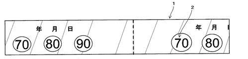
示温剤の塗布形状は、「○」、「□」、「◇」、「☆」、その他どのようなものでも良く、図4−1に示すように指示温度をそのまま数値記入したものでも良い。
数値で記載する場合は、非可逆タイプで、複数の異なる指示温度の材料を塗布する場合には、指示温度の数値を記載した表示部分の色が変化するものの方が、表示部分が解けて透明になるものより望ましい。
示温剤による指示温度は、指示温度以上になった時に検知できるが、厳密な到達温度は表示できない。例えば、70℃、80℃、90℃の指示温度の示温剤で、100℃になると、ワックスタイプでは全てとけ、変色タイプでは全て変色し、90℃以上であることが検知できる。また、ワクッスタイプで85℃になると、70℃、80℃はとけるが、90℃は解けず、同様に、変色タイプで、85℃になると、70℃、80℃は変色するが、90℃は変色しないので、85℃が検知できる。
示温テープ成形体には、テープを貼り付けた日付けが分かるように、図4−1に示すように示温剤の塗布時に日付記入欄を設けておくと便利である。さらに、示温剤塗布部も示温剤溶融後は、示温剤塗布部が判りにくくなるので、図4−2に示すように示温剤塗布部に予め補助的表示用の塗料を塗布してマーキングし、塗布部を視認し易くするのも良い。
The application form of the temperature indicating agent may be “◯”, “□”, “◇”, “☆”, or any other shape, or may be a numerical value of the indicated temperature as shown in FIG. 4-1.
When describing numerical values, it is a non-reversible type, and when applying materials with different indication temperatures, the display portion with the indicated temperature values changing in color will be more clear and the display portion will be clearer. More desirable than
The indicated temperature by the temperature indicating agent can be detected when the temperature exceeds the indicated temperature, but the exact reached temperature cannot be displayed. For example, the temperature indicating agents of 70 ° C., 80 ° C., and 90 ° C. are 100 ° C. When the temperature is 100 ° C., the wax type is completely dissolved, the discolored type is all discolored, and it can be detected that the temperature is 90 ° C. or higher. When the wax type is 85 ° C., 70 ° C. and 80 ° C. can be dissolved, but 90 ° C. cannot be solved. Similarly, when the temperature is 85 ° C., the color is changed to 70 ° C. and 80 ° C., but 90 ° C. is discolored. Therefore, 85 ° C. can be detected.
As shown in FIG. 4-1, it is convenient to provide a date entry column in the temperature indicating tape molded body at the time of application of the temperature indicating agent so that the date on which the tape is applied can be understood. Furthermore, after the temperature indicating agent is also melted after the temperature indicating agent is melted, the temperature indicating agent applying portion is difficult to understand, so as shown in FIG. It is also possible to make the application part easily visible.
得られる本発明の示温テープ成形体は、長さ方向の破断伸びが100%以上である。このように、長さ方向の破断伸びが大きいので、振動や伸縮が起こる部位に対して有効である。地震などの揺れによる示温テープ成形体を貼り付けた構造体等が揺れ動いたりしても、テープがずれにくい。
さらに、本発明の示温テープ成形体は、体積抵抗率が1×10¹²以上、好ましくは1×10¹⁴Ω−cm以上、破壊電圧が10kV/mm以上、好ましくは20kV/mm以上の電気絶縁性を持つものであり、電気設備関係の構造体にも効果的に利用できる。
The obtained temperature indicating tape molded article of the present invention has a breaking elongation in the length direction of 100 % or more. Thus, since the breaking elongation in the length direction is large, it is effective for a site where vibration and expansion / contraction occur. Even if a structure with a temperature indicating tape molded body attached due to shaking such as an earthquake shakes, the tape is not easily displaced.
Furthermore, the temperature indicating tape molded product of the present invention has an electrical insulation property with a volume resistivity of 1 × 10 12 or more, preferably 1 × 10 14 Ω-cm or more, and a breakdown voltage of 10 kV / mm or more, preferably 20 kV / mm or more. It can be used effectively for structures related to electrical equipment.
本発明の示温テープ成形体は、製品の示温テープ幅の整数倍の広幅の成形体とすることができる。この場合は、示温テープ成形体をテープ長手方向に切断して所望本数の示温テープ成形体とした後、示温テープ成形体を示温剤の無い箇所で、用途に応じて幅方向に切断して、必要長さのテープ又は短尺のラベル状として使用することができる。このように、必要に応じて所望長さの示温テープ成形体として使用することができるので、ラベル状の示温ラベルと比べると、切断長さの自由度が高く、伸縮性に優れるので使いやすくなる。示温テープ成形体をテープ長手方向に切断して所望本数の示温テープ成形体とするのに、テープ長手方向にミシン目を入れて切断をし易くすることもできる。 The temperature indicating tape molded article of the present invention can be a molded article having a width that is an integral multiple of the temperature indicating tape width of the product. In this case, after the temperature indicating tape molded body is cut in the longitudinal direction of the tape to obtain the desired number of temperature indicating tape molded bodies, the temperature indicating tape molded body is cut in the width direction according to the application at a location without the temperature indicating agent, It can be used as a tape of a required length or as a short label. Thus, since it can be used as a temperature-indicating tape molded body having a desired length as required, it is easy to use because it has a high degree of freedom in cutting length and is excellent in elasticity compared to a label-like temperature indicating label. . In order to cut the temperature indicating tape molded body in the longitudinal direction of the tape to obtain the desired number of temperature indicating tape molded bodies, a perforation may be provided in the longitudinal direction of the tape to facilitate cutting.
本発明の示温テープ成形体において、示温テープ成形体を所望幅に切断した後或いはもともと所望幅に製造した示温テープ成形体を種々のパターンに示温剤を塗布した後、示温テープ成形体の非塗布部に、テープの長さ方向にミシン目を入れて、長さ方向に裁断し易くしたことで、示温テープ成形体をミシン目位置で切断すれば、容易に切断して所望幅の示温テープとすることができる。また、前記の所望幅(製品幅)の示温テープを幅方向にミシン目を入れて、ミシン目に沿って切断することで、必要長さのテープとすることができる。 In the temperature indicating tape molded body of the present invention, after the temperature indicating tape molded body is cut to a desired width or after the temperature indicating tape molded body originally manufactured to a desired width is applied to various patterns, the temperature indicating tape molded body is not applied. By making perforations in the length direction of the tape in the part and making it easy to cut in the length direction, if the temperature indicating tape molded product is cut at the perforation position, it can be easily cut and the temperature indicating tape of the desired width can be obtained. can do. Moreover, the temperature-indicating tape having the desired width (product width) is perforated in the width direction and cut along the perforations, whereby a tape having a required length can be obtained.
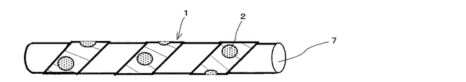
本発明の示温テープ成形体を、ケーブル又はケーブル保護管等の検査対象物7の長手方向に対して、直交する方向に1回転以上巻回して固定する(図5参照)か、長手方向に1回転以上螺旋巻きして固定して(図6参照)使用することができる。例えば、細径のケーブル又は細径ケーブルのより線などに使用する場合には、本発明の示温テープ成形体の一端をケーブルに固定した後、前記示温テープ成形体を前記ケーブル又は前記より線と直交する方向に張力を加えながら1回転以上巻回して他端を固定することができ、示温テープ成形体に張力が加えられた状態で巻回されているので、巻きつけられた示温テープが緩みにくい効果がある。
The temperature indicating tape molded body of the present invention is wound and fixed one or more times in a direction orthogonal to the longitudinal direction of the
また、前記ケーブル又はより線に示温テープ成形体を巻き付ける時に、ラセン巻きを行ないその巻き回数を多くすれば、示温剤塗布部を複数回繰り返して、同一方向に向けて表示することができるので、示温テープが緩みにくい効果のみでなく、示温剤の温度変化を読み取りやすい利点がある。
逆に、内部に複数のケーブルが収納されている太径のケーブル保護管に示温テープ成形体を巻き付ける時には、複数本のいずれのケーブルが異常事態で昇温するか不明なために、ケーブル全周に渡って、所望長さの示温テープ成形体を巻き付けなければならないため、螺旋巻きが有効である。このようにすれば、ラベルをケーブル保護管の周囲全長に渡って、多数貼り付けることが不要になる。
Also, when winding the temperature indicating tape molded body around the cable or stranded wire, if the spiral winding is performed and the number of windings is increased, the temperature indicating agent application part can be repeated multiple times and displayed in the same direction. In addition to the effect that the temperature indicating tape is not easily loosened, there is an advantage that the temperature change of the temperature indicating agent can be easily read.
On the other hand, when winding the temperature tape molded body around a large diameter cable protection tube containing multiple cables inside, it is unclear which of the multiple cables will heat up due to an abnormal situation. Therefore, spiral winding is effective because a temperature-formed tape molded body having a desired length has to be wound. In this way, it is not necessary to apply a large number of labels over the entire circumference of the cable protection tube.
本発明の示温テープ成形体は、ケーブル又はケーブル保護管の温度表示以外にも使用できる。例えば、保護管等の構造材料又は構造物の温度変化を示温テープ成形体で検知するために、構造材料又は構造物の周囲に、前記構造材料又は構造物の周囲を覆うように示温テープ成形体を巻き付けることができる。このように、構造体に示温テープを巻き付ける時に、巻き付け方としては、1回以上、直交巻き又は螺旋巻きを行なうことができる。ここで、地震などで、大きなゆれがあった場合でも、示温テープ成形体は、テープの伸びがおおきいので、緩むことはない。 The temperature indicating tape molded body of the present invention can be used in addition to the temperature display of the cable or cable protection tube. For example, in order to detect a temperature change of a structural material such as a protective tube or a structure with the temperature-increasing tape molded body, the temperature-increasing tape molded body is arranged around the structural material or the structure so as to cover the periphery of the structural material or the structure Can be wound. Thus, when the temperature indicating tape is wound around the structure, the winding can be performed at least once, orthogonal winding or spiral winding. Here, even if there is a large fluctuation due to an earthquake or the like, the temperature indicating tape molded body does not loosen because the tape stretches greatly.
本発明の示温テープ成形体は、ケーブル保護管の温度表示に使用するときでも、異なる形で使用できる。例えば、保護管の1箇所にケーブルが片寄って配置されている場合は、塗布部と非塗布部が交互に繰り返された示温テープ成形体をケーブル保護管の長手方向に、沿わせて貼り付けることができる。これにより、示温テープ成形体を貼り付けたいずれの位置での温度上昇をも示温テープにより、検知することができる。 The temperature indicating tape molded body of the present invention can be used in different forms even when used to display the temperature of the cable protection tube. For example, when the cable is arranged at one place on the protective tube, a temperature indicating tape molded body in which the coating part and the non-coating part are alternately repeated is pasted along the longitudinal direction of the cable protection pipe. Can do. Thereby, the temperature rise at any position where the temperature indicating tape molded body is attached can be detected by the temperature indicating tape.
また、ビルの屋内配線に用いる配線用バスダクト等構造物の内面に、示温テープ成形体を貼り付け、漏電や火事などの温度上昇を検知する場合には、配線用バスダクト内面に貼り付けることができるが、各階ごとにバスダクトの取り出し口が設けられるために、所定長さごとに、温度検知が必要となるが、必ずしもバスダクト全長に渡って温度検知を行なう必要がない。このように、間隔を空けて必要部分のみに示温テープを貼り付けて、温度検知を行なうことも可能である。また、直交巻きや螺旋巻き、直線的な貼り付けなどの種々の形の巻き付け方ができ、特に螺旋巻きではラップ量を変えることができる。 In addition, when a temperature indicating tape molded body is affixed to the inner surface of a structure such as a wiring bus duct used for indoor wiring in a building and a temperature rise such as electric leakage or fire is detected, it can be affixed to the inner surface of the wiring bus duct However, since a bus duct outlet is provided for each floor, temperature detection is required for each predetermined length, but it is not always necessary to detect temperature over the entire length of the bus duct. In this way, it is also possible to perform temperature detection by attaching a temperature indicating tape only to a necessary part with an interval. In addition, various forms of winding such as orthogonal winding, spiral winding, and linear pasting can be performed, and the amount of wrapping can be changed particularly in spiral winding.
次に、添付の図面を参照しながら本発明の示温テープについてさらに詳しく説明する。
本発明の示温テープは一方の面がコロナ処理され、他方の面が粘着層を設けたポリオレフィン系黒色フィルムの基材を用い、コロナ処理面に示温剤をグラビア印刷し、その上にフッ素樹脂等の透明のプラスチック粘着フィルムの保護層を貼り合わせて示温テープ成形体を作製する。
Next, the temperature indicating tape of the present invention will be described in more detail with reference to the accompanying drawings.
The temperature indicating tape of the present invention uses a polyolefin black film base material on which one surface is corona-treated and the other surface is provided with an adhesive layer, and the temperature indicating agent is gravure-printed on the corona-treated surface, and a fluororesin or the like thereon. A protective tape layer of a transparent plastic adhesive film is bonded together to produce a temperature indicating tape molded body.
得られた示温テープ成形体は、次のようにしてその特性を調べた。
(a)伸び:
JIS K 6251に準拠し、その伸び(%)を、ダンベル状1号形、引張速度500mm/分の条件で測定した。
(b)巻付作業性:
約φ30mmのポリエチレン(PE)被覆電線に1/4ラップで試験テープを巻きつけ、その作業性の良し悪しを官能試験により評価した。
(c)耐振動性:
約φ30mm、長さ500mmのポリエチレン(PE)被覆電線の中央部約200mmに試験テープを巻き付けた又は貼り付けた試料の両端を固定し、振動試験機にかけ(試験条件は、振幅:全振幅2.0〜2.5mm、加速度:34.3m/s2、振動回数:10万回)、テープの剥がれ、破れ等の状況を観察した。
(d)耐水性:
降雨を想定して常温水中に24時間浸漬した後変色、誤発色を観察した。
(e)体積抵抗率:
JIS K 6911に準拠して測定した。
(f)破壊電圧:
JIS K 6911に準拠して測定した。
(g)耐候性:
JIS K 7350-2に準拠したウエザロ促進耐候性試験で行った。
The obtained temperature indicating tape molded body was examined for its characteristics as follows.
(A) Elongation:
In accordance with JIS K 6251, the elongation (%) was measured under the conditions of dumbbell No. 1 type and tensile speed of 500 mm / min.
(B) Winding workability:
A test tape was wound around a polyethylene (PE) -coated electric wire having a diameter of about 30 mm with a 1/4 wrap, and whether the workability was good or bad was evaluated by a sensory test.
(C) Vibration resistance:
A test tape is wound around or attached to a central part of a polyethylene (PE) -coated electric wire having a diameter of about 30 mm and a length of about 500 mm, and both ends of the sample are fixed and applied to a vibration tester (test conditions are: amplitude:
(D) Water resistance:
Assuming rainfall, after being immersed in room temperature water for 24 hours, discoloration and miscoloration were observed.
(E) Volume resistivity:
Measurement was performed in accordance with JIS K 6911.
(F) Breakdown voltage:
Measurement was performed in accordance with JIS K 6911.
(G) Weather resistance:
The weather resistance accelerated weathering test was conducted in accordance with JIS K 7350-2.
[実施例1]
図1は実施例1の示温テープの断面図である。
基材4は、ポリエチレン30質量部/EVA70質量部ブレンド系フィルム(カーボン1.5%含有)の一方の面にコロナ処理を行い、他方の面にアクリル系粘着剤0.03mm厚さの粘着層5を設けた厚さ0.20mm黒色フィルムである。
示温剤2は、90℃タイプのWAX示温インク(商品名:「WL−90」、アセイ工業(株)製)である。
保護層3は、厚さ0.05mmのフッ素樹脂の透明のプラスチック粘着フィルム(商品名:「DXフィルム」、電気化学(株)製)である。この外面はフッ素樹脂であるため適度な離型性がある。
この黒色の基材フィルム4のコロナ処理面に示温剤2をシルク印刷で間歇的に白丸状に塗布し、その上に保護フィルム3を貼り合わせた。
これを図2に示すように紙管製の巻き芯6に巻き取り、幅方向示温剤の無い箇所で裁断し、長さ3mのノンセパレーターのテープ状とした。
[Example 1]
1 is a cross-sectional view of a temperature indicating tape of Example 1. FIG.
The
The
The
On the corona-treated surface of the
As shown in FIG. 2, this was wound around a core 6 made of a paper tube and cut at a place where there was no width direction temperature indicating agent to form a non-separator tape having a length of 3 m.
本実施例の示温剤は90℃タイプであり、金属パイプに巻きつけてパイプを加熱し、90℃で1分以内に透明になり白丸が無くなり下地の黒色が明瞭になった。
本テープの伸びは200%、電気絶縁性は体積抵抗率で5×10¹⁴Ω−cm、破壊電圧は45kV/mmと非常に良好であった。耐候性試験では2000時間経過後も変色、誤発色は無く明瞭であった。また、耐水性試験では変色、誤発色は無く明瞭であった。巻付作業性も良好で、耐振動性は、テープの剥がれ、破れ等の状況を観察したが、異常は見られなかった。
The temperature indicating agent of this example was a 90 ° C. type, and was wrapped around a metal pipe to heat the pipe, and became transparent within 1 minute at 90 ° C., and the white circle disappeared and the underlying black became clear.
The elongation of this tape was 200%, the electrical insulation was 5 × 10 14 Ω-cm in terms of volume resistivity, and the breakdown voltage was very good at 45 kV / mm. In the weather resistance test, there was no discoloration or false coloration even after 2000 hours, and it was clear. Further, in the water resistance test, there was no discoloration or erroneous color development and it was clear. Winding workability was also good, and vibration resistance was observed such as tape peeling and tearing, but no abnormality was found.
[実施例2]
基材4は、黒色ポリエチレンフィルム(厚さ0.20mm)で一方の面にコロナ処理をし、他面は実施例1と同様の粘着層5を設け、粘着面に離型紙を付けた。
示温剤2は、70℃タイプのWAX示温インク(商品名:「WL−70」、アセイ工業(株)製)である。
保護層3は透明のポリプロピレン粘着フィルム(厚さ0.10mm)である。
実施例1と同様に加工し、1m長さのテープ状とした。但し、離型紙を挿入したテープ状である。
本実施例の示温剤は70℃タイプであり、金属パイプに巻きつけてパイプを加熱し、70℃で1分以内に透明になり白丸が無くなり下地の黒色が明瞭になった。
本テープの伸びは150%、電気絶縁性は体積抵抗率で2×10¹⁴Ω−cm、破壊電圧は42kV/mmと非常に良好であった。耐候性は1000時間経過後保護層の変色がみられ、明瞭さは悪くなったが500時間までは変色は見られなかった。
耐水性試験では変色、誤発色は無く明瞭であった。巻付作業性と耐振動性も実施例1と同様に評価し、何れも良好であった。
[Example 2]
The
The
The
It processed like Example 1 and it was set as the tape shape of 1 m length. However, it is in the form of a tape with a release paper inserted.
The temperature indicating agent of this example was a 70 ° C. type. The pipe was heated by being wrapped around a metal pipe, and became transparent within 1 minute at 70 ° C., and the white circle disappeared and the underlying black became clear.
The elongation of this tape was 150%, the electrical insulation property was 2 × 10 14 Ω-cm in terms of volume resistivity, and the breakdown voltage was very good at 42 kV / mm. As for weather resistance, discoloration of the protective layer was observed after 1000 hours, and the clarity was deteriorated, but no discoloration was observed until 500 hours.
The water resistance test was clear with no discoloration or false color development. Winding workability and vibration resistance were also evaluated in the same manner as in Example 1, and both were good.
[実施例3]
基材と保護層は実施例1と同様であるが、示温剤はアセイ工業製のWAX示温インク「WL−70」、「WL−90」、「WL−110」(いずれも商品名)の3種類とし、3台の印刷機を並べて流れ方向に3種類の示温剤を順次印刷した。印刷は白丸ではなく数字で70、90、110とした。
また、長さ方向の非印刷部にミシン目を入れ、更に日付を書き込める欄を設け、場合により適宜ラベルと同じようにも使えるようにした。
実施例1と同様に加工し、2m長さのノンセパレーターのテープ状とした。
本実施例の示温剤は70℃と90℃、110℃の3タイプであり、金属パイプに巻きつけてパイプを加熱し、各温度毎にそれぞれの示温剤が1分以内に透明になり温度を示す数字が見えなくなり下地の黒色が明瞭になった。
本テープの伸びは190%、電気絶縁性は体積抵抗率で4×10¹⁴Ω−cm、破壊電圧は44kV/mmと非常に良好であった。耐候性は2000時間経過後も変色、誤発色は無く明瞭であった。
また、耐水性試験では変色、誤発色は無く明瞭であった。巻付作業性と耐振動性も実施例1と同様に評価し、何れも良好であった。
[Example 3]
The base material and the protective layer are the same as in Example 1, except that the temperature indicating agent is WAX temperature ink “WL-70”, “WL-90”, “WL-110” (all trade names) manufactured by ASEI Three types of temperature indicating agents were sequentially printed in the flow direction by arranging three printing machines. Printing was made with
In addition, a perforation is made in the non-printing portion in the length direction, and a column for writing the date is provided, so that it can be used in the same manner as a label depending on the case.
It processed like Example 1, and it was set as the tape shape of a non-separator of 2 m length.
There are three types of temperature indicating agents in this example: 70 ° C., 90 ° C., and 110 ° C., and each pipe is heated around a metal pipe, and each temperature indicating agent becomes transparent within 1 minute at each temperature. The numbers shown were not visible, and the black background became clear.
The elongation of this tape was 190%, the electrical insulation property was 4 × 10 14 Ω-cm in terms of volume resistivity, and the breakdown voltage was very good at 44 kV / mm. The weather resistance was clear with no discoloration or false coloration after 2000 hours.
Further, in the water resistance test, there was no discoloration or erroneous color development and it was clear. Winding workability and vibration resistance were also evaluated in the same manner as in Example 1, and both were good.
[比較例1]
基材4は、黒色ポリエチレンフィルム(厚さ0.20mm)で一方の面にコロナ処理をし、他面は実施例1と同様の粘着層5を設けた。
示温剤2は、90℃タイプのWAX示温インク(商品名:「WL−90」、アセイ工業(株)製)である。
保護層3は、透明の片面シリコーン処理ポリエステル粘着フィルム(厚さ0.05mm)である。
実施例1と同様に加工し、2m長さのノンセパレーターのテープ状とした。
本実施例の示温剤は90℃タイプであり、金属パイプに巻きつけてパイプを加熱し、90℃で1分以内に透明になり白丸が無くなり下地の黒色が明瞭になった。
本示温テープの伸びは50%、電気絶縁性は体積抵抗率で5×10¹⁴Ω−cm、破壊電圧は43kV/mmと非常に良好であった。耐候性は1500時間経過後保護層の変色がみられ、明瞭さはやゝ悪くなったが1000時間までは変色は見られなかった。
また、耐水性試験では変色、誤発色は無く明瞭であった。巻付作業性と耐振動性も実施例1と同様に評価し、巻付作業性は実施例1と比べやゝ劣ったが、耐振動性は実施例1と同様異常は見られなかった。
[ Comparative Example 1 ]
The
The
The
It processed like Example 1, and it was set as the tape shape of a non-separator of 2 m length.
The temperature indicating agent of this example was a 90 ° C. type, and was wrapped around a metal pipe to heat the pipe, and became transparent within 1 minute at 90 ° C., and the white circle disappeared and the underlying black became clear.
The elongation of the temperature indicating tape was 50%, the electric insulation was 5 × 10 14 Ω-cm in terms of volume resistivity, and the breakdown voltage was 43 kV / mm, which was very good. As for the weather resistance, discoloration of the protective layer was observed after 1500 hours, and although the clarity was slightly worse, no discoloration was observed until 1000 hours.
Further, in the water resistance test, there was no discoloration or erroneous color development and it was clear. The winding workability and vibration resistance were also evaluated in the same manner as in Example 1. The winding workability was slightly inferior to that of Example 1, but the vibration resistance was not abnormal as in Example 1.
[比較例2]
紙の片面に発色タイプの示温剤が塗布され、その上にプラスチックフィルムの保護層があり、逆面は粘着剤が施されている、市販の示温ラベル(商品名:「サーモラベルLI−90」、日油技研(株)製)を利用した。
伸びはほとんど無く0%、耐候性は500時間、耐水性は24時間でいずれも変色が見られた。電線へ巻きつけることはできず、貼り付けた後、振動試験機にかけたが剥がれが見られた。
[Comparative Example 2 ]
A commercially available temperature label (trade name: “Thermo Label LI-90”), in which a color-type temperature indicating agent is coated on one side of a paper, a plastic film protective layer is applied on the surface, and an adhesive is applied on the opposite side. , Made by NOF Engineering Co., Ltd.).
There was almost no elongation, 0%, weather resistance was 500 hours, and water resistance was 24 hours. It was not possible to wrap it around an electric wire, and after being attached, it was applied to a vibration tester, but peeling was observed.
前記実施例等と市販の示温ラベルを比較して評価を行った結果を下記の表1に示した。
Table 1 below shows the results of evaluation by comparing the examples and the like with commercially available temperature labels.

以上のことから、本発明の示温テープ成形体は、テープを巻くだけという単純作業にもかかわらず、効率の良い機能性を示すことが出来、長尺用途や連続用途向け、特に、液輸送パイプ、バスダクト、柱状構造物等に極めて高い実用性があることが分かった。 From the above, the temperature indicating tape molded product of the present invention, despite only that simple task with tape, efficient it is possible to show a good functionality, long use and continuous applications, especially liquid transport It was found that pipes, bus ducts, columnar structures, etc. have extremely high practicality.
1 示温テープ成形体
2 示温剤
3 保護層
4 プラスチック系基材
5 粘着層
6 巻き芯
7 検査対象物
DESCRIPTION OF
Claims (9)
前記プラスチック基材は、ポリエチレン、ポリプロピレン、エチレン−酢酸ビニル共重合体(EVA)、ポリエチレンとエチレン−酢酸ビニル共重合体(EVA)との混合物、又はこれらにゴムもしくは熱可塑性エラストマーをブレンドしたものからなり、
示温剤が塗布された基材の面側には、示温剤を保護するための透明保護層として透明のプラスチックフィルムが設けられ、かつ、前記基材の示温剤を塗布する面側にはコロナ処理による被接着処理が施されており、
前記基材の示温剤が塗布された面に対しその他方の面には、粘着層が設けられ、
体積抵抗率が1×10¹²Ω−cm以上で、破壊電圧が10kV/mm以上の電気絶縁性を持ち、長さ方向の破断伸びが100%以上であり、
構造体(除く電線・ケーブル)に適用することを特徴とする巻き付け性に優れた示温テープ成形体。 At least one side of the colored plastic base material is coated with a temperature indicating agent composed of a wax mixture that melts and becomes transparent to reveal the base color of the base,
The plastic substrate is made of polyethylene, polypropylene, ethylene-vinyl acetate copolymer (EVA), a mixture of polyethylene and ethylene-vinyl acetate copolymer (EVA), or a blend of rubber or thermoplastic elastomer. Become
A transparent plastic film is provided as a transparent protective layer for protecting the temperature-indicating agent on the surface side of the substrate to which the temperature-indicating agent is applied, and the surface side of the substrate to which the temperature-indicating agent is applied is corona-treated. Adhesive treatment by
An adhesive layer is provided on the other surface of the substrate on which the temperature indicating agent is applied,
The volume resistivity is 1 × 10 12 Ω-cm or more, the breakdown voltage is 10 kV / mm or more, has electrical insulation, and the breaking elongation in the length direction is 100% or more,
A temperature indicating tape molded body with excellent winding properties, characterized by being applied to structures (excluding electric wires and cables).
前記着色されたプラスチック系基材の一方の面に、前記溶融して透明になり下地の基材色が現れるワックス混合物からなる示温剤を塗布し、
前記示温剤が塗布された基材の面側には、示温剤を保護するための前記透明保護層を設け、
前記基材の示温剤が塗布された面に対しその他方の面には、前記粘着層を設け、
前記保護層表面に離型性を持たせたノンセパレーターテープとするに当たり、
前記基材の示温剤を塗布する面側にコロナ処理による被接着処理を施し、体積抵抗率が1×10¹²Ω−cm以上で、破壊電圧が10kV/mm以上の電気絶縁性を持ち、長さ方向の破断伸びが100%以上であり、構造体(除く電線・ケーブル)に適用すること特徴とする示温テープ成形体の製造方法。
A method for producing the temperature indicating tape molded body according to any one of claims 1 to 6,
On one side of the colored plastic-based substrate, a temperature indicating agent composed of a wax mixture that melts and becomes transparent and reveals the base color of the base is applied.
On the surface side of the substrate on which the temperature indicating agent is applied, the transparent protective layer for protecting the temperature indicating agent is provided,
The adhesive layer is provided on the other surface of the substrate on which the temperature indicating agent is applied,
In making a non-separator tape having release properties on the surface of the protective layer,
The surface side of the base material to which the temperature indicating agent is applied is subjected to a corona treatment, and has a volume resistivity of 1 × 10 12 Ω-cm or more and a breakdown voltage of 10 kV / mm or more. A method for producing a temperature indicating tape molded body characterized by having a breaking elongation in the vertical direction of 100% or more and applied to a structure (excluding electric wires and cables).
Priority Applications (1)
| Application Number | Priority Date | Filing Date | Title |
|---|---|---|---|
| JP2011175456A JP5117601B2 (en) | 2008-09-12 | 2011-08-10 | Temperature indicating tape molded body and method of using the same |
Applications Claiming Priority (3)
| Application Number | Priority Date | Filing Date | Title |
|---|---|---|---|
| JP2008235657 | 2008-09-12 | ||
| JP2008235657 | 2008-09-12 | ||
| JP2011175456A JP5117601B2 (en) | 2008-09-12 | 2011-08-10 | Temperature indicating tape molded body and method of using the same |
Related Parent Applications (1)
| Application Number | Title | Priority Date | Filing Date |
|---|---|---|---|
| JP2009021937A Division JP4956564B2 (en) | 2008-09-12 | 2009-02-02 | Temperature indicating tape molded body and method of using the same |
Publications (3)
| Publication Number | Publication Date |
|---|---|
| JP2011221045A JP2011221045A (en) | 2011-11-04 |
| JP2011221045A5 JP2011221045A5 (en) | 2012-09-27 |
| JP5117601B2 true JP5117601B2 (en) | 2013-01-16 |
Family
ID=42254390
Family Applications (2)
| Application Number | Title | Priority Date | Filing Date |
|---|---|---|---|
| JP2009021937A Expired - Fee Related JP4956564B2 (en) | 2008-09-12 | 2009-02-02 | Temperature indicating tape molded body and method of using the same |
| JP2011175456A Expired - Fee Related JP5117601B2 (en) | 2008-09-12 | 2011-08-10 | Temperature indicating tape molded body and method of using the same |
Family Applications Before (1)
| Application Number | Title | Priority Date | Filing Date |
|---|---|---|---|
| JP2009021937A Expired - Fee Related JP4956564B2 (en) | 2008-09-12 | 2009-02-02 | Temperature indicating tape molded body and method of using the same |
Country Status (1)
| Country | Link |
|---|---|
| JP (2) | JP4956564B2 (en) |
Families Citing this family (6)
| Publication number | Priority date | Publication date | Assignee | Title |
|---|---|---|---|---|
| KR101304503B1 (en) * | 2012-01-04 | 2013-09-05 | 송범식 | Apparatus for heating pipe line and manufacturing method of the same |
| JP6422648B2 (en) * | 2013-12-27 | 2018-11-14 | スリーエム イノベイティブ プロパティズ カンパニー | Cable connection structure, cable connection kit, and connection structure forming method |
| KR101875336B1 (en) | 2017-09-30 | 2018-07-05 | 이창혁 | printed member using thermochromic ink |
| JP7465108B2 (en) * | 2019-02-25 | 2024-04-10 | グンゼ株式会社 | Temperature-sensitive dye film |
| JP7328780B2 (en) * | 2019-04-02 | 2023-08-17 | 中日本高速道路株式会社 | CABLE STRENGTH DECISION DETERMINATION METHOD AND HEAT RECEIVED TEMPERATURE HISTORY DISPLAY STRUCTURE USED IN THE METHOD |
| JP2023007041A (en) * | 2021-07-01 | 2023-01-18 | Koa株式会社 | Temperature sensor |
Family Cites Families (16)
| Publication number | Priority date | Publication date | Assignee | Title |
|---|---|---|---|---|
| JPS63118626A (en) * | 1986-04-30 | 1988-05-23 | Mitsui Toatsu Chem Inc | Indicator for storage temperature control and its manufacture |
| JPH0745262B2 (en) * | 1990-02-16 | 1995-05-17 | 株式会社巴川製紙所 | Thermal recording |
| JPH05164630A (en) * | 1991-12-19 | 1993-06-29 | Hitachi Zosen Corp | Cable temperature measurement method in suspension bridge |
| JP2808510B2 (en) * | 1992-05-01 | 1998-10-08 | 大阪シーリング印刷 株式会社 | Non-sepa type label base paper |
| JPH08137392A (en) * | 1994-09-14 | 1996-05-31 | Petsutaa:Kk | Successive label body |
| JPH1062269A (en) * | 1996-08-22 | 1998-03-06 | Asahi Electric Works Ltd | Overheating detection display device |
| JP2000321148A (en) * | 1999-05-15 | 2000-11-24 | Kamoi Kakoshi Kk | Seal or label for displaying control state of product |
| JP2001234134A (en) * | 2000-02-25 | 2001-08-28 | Pilot Ink Co Ltd | Reversible thermochromic adhesive tape |
| JP2001247828A (en) * | 2000-03-02 | 2001-09-14 | Pilot Ink Co Ltd | Reversible thermochromic adhesive tape |
| JP2002105416A (en) * | 2000-10-04 | 2002-04-10 | Toyo Chem Co Ltd | Adhesive tape |
| JP4194520B2 (en) * | 2004-03-31 | 2008-12-10 | 日油技研工業株式会社 | Irreversible temperature control material |
| JP4358042B2 (en) * | 2004-06-18 | 2009-11-04 | 大日本印刷株式会社 | Laminated body with indicator for heat treatment and method for producing the same |
| JP4789083B2 (en) * | 2004-07-15 | 2011-10-05 | 株式会社ジークエスト | Temperature sensitive seal |
| JP2006133190A (en) * | 2004-11-09 | 2006-05-25 | Matsushita Electric Works Ltd | Thermal history management sheet and thermal history management method |
| JP4744996B2 (en) * | 2005-09-09 | 2011-08-10 | 花王株式会社 | Temperature history display material and packaging material using the same |
| JP2008238768A (en) * | 2007-03-29 | 2008-10-09 | Sato Corp | Thermal recording sheet and method of using the same |
-
2009
- 2009-02-02 JP JP2009021937A patent/JP4956564B2/en not_active Expired - Fee Related
-
2011
- 2011-08-10 JP JP2011175456A patent/JP5117601B2/en not_active Expired - Fee Related
Also Published As
| Publication number | Publication date |
|---|---|
| JP2010091547A (en) | 2010-04-22 |
| JP4956564B2 (en) | 2012-06-20 |
| JP2011221045A (en) | 2011-11-04 |
Similar Documents
| Publication | Publication Date | Title |
|---|---|---|
| JP5117601B2 (en) | Temperature indicating tape molded body and method of using the same | |
| US9640300B2 (en) | Cable having a thin film material and methods of preventing discoloration damage to a cable having a thin film material | |
| JP2011221045A5 (en) | ||
| RU213269U1 (en) | Device for marking electrical equipment elements for recording the maximum overheating temperature of the equipment surface | |
| US20080261012A1 (en) | Heat-reflecting adhesive tape | |
| JP2010091547A5 (en) | ||
| CN104484973B (en) | A kind of composite cable heat fire detector | |
| JP6129543B2 (en) | Self-adhesive film and electric wire binding method using the same | |
| EP2077441A2 (en) | Thermometer material | |
| RU209916U1 (en) | CABLE PRODUCT THAT CHANGES COLOR DEPENDING ON TEMPERATURE | |
| RU213149U1 (en) | Device for marking electrical equipment for registering overheating of electrical equipment components | |
| US20170154549A1 (en) | Versatile pipe marker tape | |
| US20080144699A1 (en) | Method of sensing high surface temperatures in an aircraft | |
| JP6556206B2 (en) | Multi-layer adhesive assembly | |
| RU2199051C1 (en) | Anticorrosion insulating tape | |
| RU223351U1 (en) | Thermal indicator clip for several threshold temperatures | |
| RU219296U1 (en) | Device for registering exceeding the threshold temperature | |
| US20250182929A1 (en) | Indicating cable temperature with chromogenic polymer coatings | |
| JP6749259B2 (en) | Conductive paint tape | |
| RU218752U1 (en) | Reflective equipment marking device for registering equipment surface temperature exceedances | |
| JP3765667B2 (en) | Adhesive film | |
| JP2013173904A (en) | Resin-made tape and method for producing the same | |
| JP4947261B2 (en) | Electrically insulated molded body with irreversible temperature-sensitive color changer having an intervening protective layer and its production method | |
| CN222337972U (en) | Component with temperature identification structure and cable | |
| JP2006300584A (en) | Temperature indicator |
Legal Events
| Date | Code | Title | Description |
|---|---|---|---|
| A621 | Written request for application examination |
Free format text: JAPANESE INTERMEDIATE CODE: A621 Effective date: 20120118 |
|
| A521 | Written amendment |
Free format text: JAPANESE INTERMEDIATE CODE: A523 Effective date: 20120808 Free format text: JAPANESE INTERMEDIATE CODE: A821 Effective date: 20120808 |
|
| A521 | Written amendment |
Free format text: JAPANESE INTERMEDIATE CODE: A821 Effective date: 20120822 |
|
| A871 | Explanation of circumstances concerning accelerated examination |
Free format text: JAPANESE INTERMEDIATE CODE: A871 Effective date: 20120822 |
|
| A975 | Report on accelerated examination |
Free format text: JAPANESE INTERMEDIATE CODE: A971005 Effective date: 20120906 |
|
| TRDD | Decision of grant or rejection written | ||
| A01 | Written decision to grant a patent or to grant a registration (utility model) |
Free format text: JAPANESE INTERMEDIATE CODE: A01 Effective date: 20120925 |
|
| A01 | Written decision to grant a patent or to grant a registration (utility model) |
Free format text: JAPANESE INTERMEDIATE CODE: A01 |
|
| A61 | First payment of annual fees (during grant procedure) |
Free format text: JAPANESE INTERMEDIATE CODE: A61 Effective date: 20121017 |
|
| R151 | Written notification of patent or utility model registration |
Ref document number: 5117601 Country of ref document: JP Free format text: JAPANESE INTERMEDIATE CODE: R151 |
|
| FPAY | Renewal fee payment (event date is renewal date of database) |
Free format text: PAYMENT UNTIL: 20151026 Year of fee payment: 3 |
|
| LAPS | Cancellation because of no payment of annual fees |