JP5116705B2 - Grill unit and heating cooker provided with the same - Google Patents
Grill unit and heating cooker provided with the same Download PDFInfo
- Publication number
- JP5116705B2 JP5116705B2 JP2009033504A JP2009033504A JP5116705B2 JP 5116705 B2 JP5116705 B2 JP 5116705B2 JP 2009033504 A JP2009033504 A JP 2009033504A JP 2009033504 A JP2009033504 A JP 2009033504A JP 5116705 B2 JP5116705 B2 JP 5116705B2
- Authority
- JP
- Japan
- Prior art keywords
- grill
- pull
- chamber
- slide rail
- arm
- Prior art date
- Legal status (The legal status is an assumption and is not a legal conclusion. Google has not performed a legal analysis and makes no representation as to the accuracy of the status listed.)
- Expired - Fee Related
Links
Images


Description
本発明は、加熱調理器において庫内調理を行うグリルユニット及びこのグリルユニットを備えた加熱調理器に関するものである。 The present invention relates to a grill unit that performs cooking in a refrigerator in a heating cooker, and a heating cooker including the grill unit.
従来の加熱調理器に、グリルケースにスライド手段によってグリル受け皿が引き出し自在に収容されるグリルを有し、上記のスライド手段は、グリルケースの両側に固定されたガイドレールと、このガイドレールに係合しグリル受け皿の両側に配設される被ガイドレールとを備え、被ガイドレールに枠材を架設してカバー枠を構成し、このカバー枠にグリル受け皿を取外し自在に載置するようにしたものがある(例えば、特許文献1参照)。 A conventional cooking device has a grill in which a grill pan is slidably accommodated in the grill case by sliding means, and the sliding means includes guide rails fixed to both sides of the grill case, and the guide rails. And a guided rail disposed on both sides of the grill pan, and a frame material is constructed on the guided rail to form a cover frame, and the grill pan is detachably mounted on the cover frame. There are some (see, for example, Patent Document 1).
また、両側のレールユニットの前部を連結するレール連結部に、受け皿の外周形状に対応した形状の受け皿保持枠を装着し、この受け皿保持枠に受け皿を着脱自在に載置するようにしたものがある(例えば、特許文献2参照)。 In addition, a tray holding frame having a shape corresponding to the outer peripheral shape of the tray is attached to the rail connecting portion that connects the front portions of the rail units on both sides, and the tray is detachably mounted on the tray holding frame. (See, for example, Patent Document 2).
特許文献1のグリルは、被ガイドレールの間に載置されたグリル受け皿のフランジの上面が、被ガイドレールの上面とほぼ同一平面上にあるため、グリル受け皿の取り外しが面倒である。
この場合、グリル受け皿の取り外しを考慮すると、被ガイドレールより高い位置にグリル受け皿を保持するか、又はグリル受け皿を両側の被ガイドレールの間隔より狭い幅に形成する必要がある。
In the grill of
In this case, considering the removal of the grill pan, it is necessary to hold the grill pan at a position higher than the guided rail, or to form the grill pan with a width narrower than the interval between the guided rails on both sides.
しかしながら、グリル受け皿を被ガイドレールより高い位置に保持すると、高さ方向の使用空間が小さくなり、また、グリル受け皿の幅を狭くすると、横方向の使用空間が小さくなるため、いずれの場合も、調理する素材の大きさが制限されることになり、好ましくない。 However, if the grill pan is held at a position higher than the guided rail, the use space in the height direction becomes small, and if the width of the grill pan is narrowed, the use space in the horizontal direction becomes small. The size of the material to be cooked is limited, which is not preferable.
また、特許文献2のグリルにおいては、受け皿の取り外しは容易であるが、特別に受け皿保持体を設けなければならないので、構造が複雑であるばかりでなく、その分コストアップになるという問題があった。 Further, in the grill of Patent Document 2, it is easy to remove the tray, but since a special tray holder must be provided, not only is the structure complicated, but there is a problem that the cost increases accordingly. It was.
本発明は、上記の課題を解決するためになされたもので、構造が簡単で使用空間が大きく、グリル受け皿の着脱が容易で使い勝手のよいグリルユニット及びこのグリルユニットを備えた加熱調理器を提供することを目的としたものである。 The present invention has been made to solve the above problems, and provides a grill unit having a simple structure, a large space for use, and an easy-to-use grill tray, and a cooking device provided with the grill unit. It is intended to do.
本発明に係るグリルユニットは、前面が開口され内壁に対向して固定ガイドレールが設けられたグリル室と、前記固定ガイドレールに摺動自在に嵌合された摺動レールと、前記グリル室の開口部を開閉するグリル扉と、一端が前記グリル扉に固定され他端が前記摺動レールに軸支されたプルダウンアーム及びほぼ中間部が前記摺動レールに軸支され下部が前記プルダウンアームの摺動穴に連結された保持アームによって構成されたプルダウン機構とからなり、前記グリル室に引出し式に収容されるグリル扉装置と、該グリル扉装置の摺動レール上に着脱自在に載置されるグリル受け皿とを備え、前記グリル扉装置を前記グリル室から引き出してプルダウン状態となったときは、前記保持アームの上端部が前記摺動レールの上面から突出するように構成したものである。 A grill unit according to the present invention includes a grill chamber in which a front surface is opened and a fixed guide rail is provided to face an inner wall, a slide rail that is slidably fitted to the fixed guide rail, and the grill chamber A grill door that opens and closes the opening, a pull-down arm having one end fixed to the grill door and the other end pivotally supported by the slide rail, and a substantially middle portion pivotally supported by the slide rail and a lower portion of the pull-down arm. It comprises a pull-down mechanism composed of a holding arm connected to a sliding hole, and is detachably mounted on a sliding door of the grill door device, which is housed in the grill chamber in a pull-out manner. When the grill door device is pulled out of the grill chamber and pulled down, the upper end of the holding arm protrudes from the upper surface of the slide rail. It is those that you have configured.
また、本発明に係る加熱調理器は、上記のグリルユニットを備えたものである。 Moreover, the cooking device according to the present invention includes the grill unit.
本発明によれば、使用空間が大きく、グリル受け皿の着脱が容易で使い勝手のよいグリルユニット及びこれを備えた加熱調理器を得ることができる。 According to the present invention, it is possible to obtain a grill unit that has a large use space, is easy to attach and detach a grill pan, and is easy to use, and a cooking device including the grill unit.
[実施の形態1]
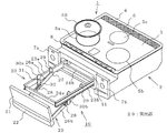
本発明の実施の形態1に係るグリルユニット20を備えた図1の加熱調理器1において、2は上面が開口したほぼ箱状の本体ケースで、上面開口部には、例えば耐熱ガラスの如き非磁性材からなり、外周に天板支持枠4が設けられた平板状の天板3が装着されている。そして、天板3の上面には、調理容器50の載置位置を示す複数の載置位置表示部5a,5b,5c(図には3個の場合が示してあるが、2個以上であればよい)が印刷により設けられている。6は天板3の後部側に設けられた吸排気口である。
[Embodiment 1]
In the
7a,7bは本体ケース2の前面の両側(一方の側又は上面の場合もある)に設けられた主操作部、8は天板支持枠3の前面側に設けられた副操作部である。なお、図示してないが、本体ケース2の天板3の載置位置表示部5a〜5cの下面には、例えば、誘導加熱コイルやヒータの如き加熱体がそれぞれ配設されており、また、これら加熱体を制御する制御部、外気取入口から取り込んだ外気により、加熱体や制御部などを冷却する送風機等が設けられている。
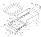
10は主操作部7a,7bの間(主操作部が一方の側に設けられている場合は、これと並行して)に設けられたグリルユニットで、本体ケース2内に設置されて前面が開口されたほぼ箱状のグリル室11と、グリル受け皿が着脱自在に載置され、グリル室11内に挿脱自在に収容される引き出し式のグリル扉装置20とからなっている。以下、このグリルユニット10につき、図2〜図6を参照して説明する。なお、図2〜図6において、グリル室11は天板を省略してある(以下の図面においても同様)。
A
グリル室11は薄い金属板をプレス加工により成形し、あるいは薄い金属板の端部どうしを溶接やねじによって接合してほぼ箱状に形成したもので、前面には本体ケース2の前面側に開口する開口部12が設けられており、後面側には本体ケース2の天板3に設けた吸排気口6に開口する排気ダクト13が設けられている。
The
また、グリル室11の両側壁内面の下部の前後方向には、断面コ字状の一対の固定ガイドレール14a,14b(図には、一方の固定ガイドレール14aのみが示してある。なお、以下の説明では単に14と記すことがある)が、開口部を対向させてねじ、溶接等により取付けられている。なお、図示してないが、グリル室11の天板の下面には、シーズヒータやハロゲンヒータの如き加熱体が配設されており、また、底板の上面には底板と所定の間隔を保って、グリル室11の背面から前面方向にかけて水平に展開されたシーズヒータ等の加熱体が配設されている。
A pair of
グリル扉装置20は、グリル扉21の背面の両側に、後述のプルダウン機構25を介して連結される断面コ字状で開口部が外側に向けられた一対の摺動レール23a,23b(以下、単に23と記すことがある)を有し、この摺動レール23a,23bは、グリル室11に設けた固定ガイドレール14a,14bの外側に、前後方向に摺動可能に嵌合される。そして、これら対向する摺動レール23a,23bの間の前後には、両者の間隔を保持し、かつ補強のための連結アーム24a,24bが固定されて枠状に形成されており、グリル扉装置20の開閉にあたって、グリル受け皿40に載置された被加熱調理物の重量バランスによるゆがみ等を生ずることがなく、スムーズに動作できるようになっている。
The
また、グリル扉装置20には、グリル扉21を引き出したときに、グリル扉21を下方に下げてグリル受け皿40やその上の被加熱調理物を取り出し易くするために、プルダウン機構25が設けられている。
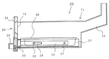
このプルダウン機構25は、一端がグリル扉21の背面側に設けたプルダウン連結アーム33(図4)に固定され、他端が連結ピン27により摺動レール23a,23bに回動自在に軸支されたプルダウンアーム26a,26b(以下、単に26と記すことがある)と、上下方向のほぼ中間部がピン31により摺動レール23a,23bに回動自在に軸支され、下部がプルダウンアーム26a,26bの長手方向に設けた摺動穴28に、ピン32を介して摺動自在に連結された保持アーム30a,30b(以下、単に30と記すことがある)とからなっている。
In addition, the
One end of the pull-
被加熱調理物を載置して調理するグリル受け皿40は、ステンレス鋼板や、例えば表面にホーロー被膜処理が施された耐食性の高い金属板などによって形成されており、中央の凹んだ皿部41の上端部には、外方に折り曲げられたフランジ42が設けられている。
The
次に、上記のように構成した本実施の形態に係るグリルユニット10の作用を説明する。
被加熱調理物(図示せず)が皿部41に載置されたグリル受け皿40は、図2〜図4に示すように、そのフランジ42が摺動レール23a,23b上に載置される。そして、ハンドル22に手を掛けてグリル扉装置20をグリル室11内に押し込むと、摺動レール23a,23bが固定レール14a,14bに沿って移動し、グリル扉21が開口部12を閉塞し、グリル扉装置20、したがってグリル受け皿40はグリル室11内に収容される。
Next, the operation of the
As shown in FIG. 2 to FIG. 4, the
このとき、プルダウンアーム26a,26bは連結ピン27を中心に回動して、摺動レール23a,23bに沿ってほぼ水平状態になり、また、保持アーム30a,30bもピン31を中心に回動すると共に、下部のピン32が摺動穴28内を前面側に移動して摺動レール23a,23bとプルダウンアーム26a,26bの間でほぼ水平状態となることにより、グリル扉21はグリル室11の開口部12を閉塞する。このときの状態を図4に示す。
At this time, the pull-down
この状態で、グリル室11の上下に設けた加熱体に通電し、グリル受け皿40上の被加熱調理物を加熱し、調理する。このとき、加熱、調理によって発生した蒸気や煙は、ダクト13を介して吸排気口5から外部に排出される。
In this state, power is supplied to the heating bodies provided at the top and bottom of the
調理が終ったときは、図5に示すように、グリル扉21の手掛け22に手を掛けて、グリル扉装置20をグリル室11から引き出す。グリル扉21を最大限に引き出すと、グリル扉21の自重や引き出した手の荷重によって、図6に示すように、プルダウンアーム26a,26bが連結ピン27を中心に水平状態から斜め下方に回動し、プルダウン状態になる。
When cooking is finished, as shown in FIG. 5, the user holds the
同時に、保持アーム30a,30bの下部に設けられてプルダウンアーム26a,26bの摺動穴28に連結されたピン32が、摺動穴28の変位に伴ってその後端部まで移動し、保持アーム30a,30bを回動させる。このとき、ピン32はプルダウンアーム26a,26bのストッパとして作用し、プルダウンアーム26a,26bはその位置に保持され、それ以上回動しない。
これにより、グリル扉21は、摺動レール23a,23bに対して斜め下方に位置する。
At the same time, the
Thereby, the
また、保持アーム30a,30bは、プルダウン状態のときはその上端部が摺動レール23a,23bの上面から突出する。これにより、グリル扉21が傾動すると同時に保持アーム30a,30bの上端部が、摺動レール23a,23b上に載置されているグリル受け皿40のフランジ42を押し上げるため、図2、図6に示すように、摺動レール23a,23bとフランジ42との間にすき間が生じる。よって、このすき間に指先や引っ掛け具を差し込むことにより、被加熱調理物が載置されたグリル受け皿40を容易に持ち上げて取り外すことができる。
Further, when the holding
このように、保持アーム30a,30bは、プルダウンアーム26a,26bの傾動に伴って回動し、グリル受け皿40を持ち上げるようにしているため、その上端部を斜めに面取りしたり、グリースを塗ったりすることで、よりスムーズに稼動することができる。
In this way, the holding
図7、図8は本実施の形態に係るグリルユニット10の他の例を示すもので、本例においては、保持アーム30a,30bを、水平状態になったときに摺動レール23a,23bからはみ出さない範囲で、上部が幅広のほぼT字状に形成し、グリル受け皿40をバランスよく安定して持ち上げるようにしたものである。
7 and 8 show another example of the
本実施の形態によれば、グリル扉装置20をグリル室11から引き出すと、プルダウンによりグリル扉21が斜め下方に傾動するため、グリル扉21の上辺とグリル受け皿40との高低差が小さくなり、グリル受け皿40やこれに載置された被加熱調理物が取り出し易くなる。
また、プルダウンにより保持アーム30a,30bの上端部がグリル受け皿40を自動的に持ち上げて、摺動レール23a,23bとの間にすき間が形成されるため、グリル受け皿40の取り外しが容易である。
According to the present embodiment, when the
Further, the upper ends of the holding
さらに、グリル受け皿40は、固定ガイドレール14a,14bの外側に嵌合した摺動レール23a,23b上にそのフランジ42を載置するようにしたので、天板との間を広く、またグリル受け皿40の幅をグリル室11の幅とほぼ等しい幅に形成することができ、これにより、グリル室11の使用空間を、グリルユニット10の使用において最大限に設定することができる。
このため、従来より大きな素材でも加熱調理することができる。
Furthermore, since the
For this reason, even a larger material than before can be cooked.
[実施の形態2]
図9〜図13は本発明の実施の形態2に係るグリルユニット及びこれを備えた加熱調理器を示すもので、実施の形態1と同一又は同じ機能の部分にはこれと同じ符号を付し、説明を省略する。
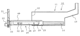
本実施の形態は、グリル扉装置20のプルダウン機構25を構成するプルダウンアーム26a,26bの後端部上面に、グリル扉装置20をグリル室11内に収容した状態では摺動レール23a,23bの高さ(幅)範囲に納まり、グリル扉装置20をグリル室11から引き出してプルダウン状態になったときは、摺動レール23a,23bの上面から突出する突出部29を設けたものである。
[Embodiment 2]
9 to 13 show a grill unit according to Embodiment 2 of the present invention and a cooking device provided with the same, and parts having the same or the same functions as those in
In the present embodiment, the sliding
本実施の形態においては、グリル扉装置20をグリル室11から引き出してプルダウン状態になると、図10〜図13に示すように、グリル受け皿40は、そのフランジ42が、プルダウンアーム26a,26bの突出部29と、保持アーム30a,30bの上端部との両者によりほぼ水平に持ち上げられ、摺動レール23a,23bとグリル受け皿40のフランジ42との間の前後方向にわたってすき間が形成される。
In the present embodiment, when the
本実施の形態の作用、効果は実施の形態1の場合とほぼ同様であるが、さらに、グリル扉装置20がグリル室11から引き出されてプルダウン状態になると、グリル受け皿40はほぼ水平に、バランスよく安定して持ち上げられるので、グリル受け皿40の取り外しがより容易になるばかりでなく、グリル受け皿40上の被加熱調理物が転がり落ちることもないなどの効果を有する。
The operation and effect of the present embodiment are substantially the same as those of the first embodiment. However, when the
[実施の形態3]
実施の形態1,2においては、グリル扉装置20の摺動レール23a,23bを、グリル室11に設けた固定レール14a,14bの外側に摺動自在に嵌合し、グリル受け皿40を摺動レール23a,23b上に載置したが、本実施の形態は、実施の形態1,2のグリルユニット10において、摺動レール23a,23bを固定レール14a,14bの内側に摺動自在に嵌合し、グリル受け皿40を、摺動レール23a,23bの前後において両者を固定する連結アーム24a,24b上に載置するようにしたものである。
本実施の形態の作用、効果は実施の形態1,2の場合とほぼ同様である。
[Embodiment 3]
In the first and second embodiments, the slide rails 23a and 23b of the
The operation and effects of the present embodiment are almost the same as those of the first and second embodiments.
上記の説明では、図示の加熱調理器1に本発明に係るグリルユニット10を設けた場合を示したが、これに限定するものではなく、他の加熱調理器にも本発明に係るグリルユニット10を適用することができる。
In the above description, a case where the illustrated
1 加熱調理器、2 本体ケース、3 天板、7a,7b 主操作部、10 グリルユニット、11 グリル室、14a,14b 固定レール、20 グリル扉装置、21 グリル扉、23a,23b 摺動レール、24a,24b 連結アーム、25 プルダウン機構、26a,26b プルダウンアーム、28 摺動穴、29 突出部、30a,30b 保持アーム、40 グリル受け皿、42 フランジ。
DESCRIPTION OF
Claims (5)
前記固定ガイドレールに摺動自在に嵌合された摺動レールと、前記グリル室の開口部を開閉するグリル扉と、一端が前記グリル扉に固定され他端が前記摺動レールに軸支されたプルダウンアーム及びほぼ中間部が前記摺動レールに軸支され下部が前記プルダウンアームの摺動穴に連結された保持アームによって構成されたプルダウン機構とからなり、前記グリル室に引出し式に収容されるグリル扉装置と、
該グリル扉装置の摺動レール上に着脱自在に載置されるグリル受け皿とを備え、
前記グリル扉装置を前記グリル室から引き出してプルダウン状態となったときは、前記保持アームの上端部が前記摺動レールの上面から突出するように構成したことを特徴とするグリルユニット。 A grill chamber having a front opening and a fixed guide rail facing the inner wall;
A slide rail slidably fitted to the fixed guide rail, a grill door that opens and closes the opening of the grill chamber, one end fixed to the grill door, and the other end pivotally supported by the slide rail The pull-down arm and a pull-down mechanism having a substantially intermediate portion pivotally supported by the slide rail and a lower portion connected to the slide hole of the pull-down arm are housed in the grill chamber in a pull-out manner. A grill door device,
A grill pan that is detachably mounted on the slide rail of the grill door device,
A grill unit characterized in that when the grill door device is pulled out of the grill chamber and pulled down, the upper end of the holding arm projects from the upper surface of the slide rail.
該グリル室の固定ガイドレールに摺動自在に嵌合され、両者の間に連結アームが固定された摺動レールと、前記グリル室の開口部を開閉するグリル扉と、一端が該グリル扉に固定され他端が前記摺動レールに軸支された一対のプルダウンアーム及び上下方向のほぼ中間部が前記摺動レールに軸止され下部が前記プルダウンアームに設けた摺動穴に摺動自在に連結された保持アームによって構成されたプルダウン機構とからなり、前記グリル室に引き出し式に収容されるグリル扉装置と、
該グリル扉装置の前記摺動レール上又は連結アーム上に着脱自在に載置されるグリル受け皿とを備え、
前記グリル扉装置を前記グリル室から引き出したときは、前記プルダウンアームが傾動して前記グリル扉が斜め下方に位置すると共に、前記保持アームの上端部が前記摺動レールの上面から突出するように構成したことを特徴とするグリルユニット。 A grill chamber having an opening on the front surface and provided with a fixed guide rail facing the lower portion of the inner wall;
A sliding rail that is slidably fitted to a fixed guide rail of the grill chamber, and a connecting arm is fixed therebetween, a grill door that opens and closes the opening of the grill chamber, and one end of the grill door A pair of pull-down arms that are fixed and pivotally supported by the slide rail, and a substantially middle portion in the vertical direction are fixed to the slide rail, and a lower portion is slidable in a slide hole provided in the pull-down arm. A grill door device comprising a pull-down mechanism constituted by linked holding arms, and being housed in a drawer manner in the grill chamber;
A grill pan that is detachably mounted on the sliding rail or the connecting arm of the grill door device,
When the grill door device is pulled out from the grill chamber, the pull-down arm is tilted so that the grill door is positioned obliquely downward, and the upper end of the holding arm protrudes from the upper surface of the slide rail. A grill unit characterized by comprising.
Priority Applications (1)
| Application Number | Priority Date | Filing Date | Title |
|---|---|---|---|
| JP2009033504A JP5116705B2 (en) | 2009-02-17 | 2009-02-17 | Grill unit and heating cooker provided with the same |
Applications Claiming Priority (1)
| Application Number | Priority Date | Filing Date | Title |
|---|---|---|---|
| JP2009033504A JP5116705B2 (en) | 2009-02-17 | 2009-02-17 | Grill unit and heating cooker provided with the same |
Publications (2)
| Publication Number | Publication Date |
|---|---|
| JP2010190456A JP2010190456A (en) | 2010-09-02 |
| JP5116705B2 true JP5116705B2 (en) | 2013-01-09 |
Family
ID=42816694
Family Applications (1)
| Application Number | Title | Priority Date | Filing Date |
|---|---|---|---|
| JP2009033504A Expired - Fee Related JP5116705B2 (en) | 2009-02-17 | 2009-02-17 | Grill unit and heating cooker provided with the same |
Country Status (1)
| Country | Link |
|---|---|
| JP (1) | JP5116705B2 (en) |
Cited By (1)
| Publication number | Priority date | Publication date | Assignee | Title |
|---|---|---|---|---|
| JP5896580B1 (en) * | 2015-03-25 | 2016-03-30 | シャープ株式会社 | Cooker |
Families Citing this family (2)
| Publication number | Priority date | Publication date | Assignee | Title |
|---|---|---|---|---|
| WO2021149585A1 (en) * | 2020-01-21 | 2021-07-29 | シャープ株式会社 | Cooker |
| CN114010070A (en) * | 2021-11-12 | 2022-02-08 | 广东美的厨房电器制造有限公司 | Bearing device and cooking appliance |
Family Cites Families (3)
| Publication number | Priority date | Publication date | Assignee | Title |
|---|---|---|---|---|
| JPS5546893Y2 (en) * | 1976-05-14 | 1980-11-04 | ||
| JPS56153712U (en) * | 1980-04-17 | 1981-11-17 | ||
| JP5023822B2 (en) * | 2007-06-08 | 2012-09-12 | 三菱電機株式会社 | Grill unit and heating cooker provided with the same |
-
2009
- 2009-02-17 JP JP2009033504A patent/JP5116705B2/en not_active Expired - Fee Related
Cited By (1)
| Publication number | Priority date | Publication date | Assignee | Title |
|---|---|---|---|---|
| JP5896580B1 (en) * | 2015-03-25 | 2016-03-30 | シャープ株式会社 | Cooker |
Also Published As
| Publication number | Publication date |
|---|---|
| JP2010190456A (en) | 2010-09-02 |
Similar Documents
| Publication | Publication Date | Title |
|---|---|---|
| US9109804B2 (en) | Appliance with vertically adjustable rack | |
| JP5253210B2 (en) | Induction heating cooker | |
| JP5116705B2 (en) | Grill unit and heating cooker provided with the same | |
| JP6552384B2 (en) | Cooker | |
| JP2015231469A (en) | Heating cooker | |
| JP2010043847A (en) | Gas cooking appliance | |
| JP2008304107A (en) | Cooking stove device | |
| JP5363835B2 (en) | Cooker | |
| US1851853A (en) | Broiler | |
| JP2005337651A (en) | Heating cooker | |
| JP5367135B2 (en) | Induction heating cooker | |
| JP7440909B2 (en) | Stove with grill | |
| JP2007051808A (en) | Heating cooker | |
| JP3113927U (en) | Kiritanpo ware | |
| JP5854886B2 (en) | Cooker | |
| JP2001254960A (en) | Built-in oven | |
| JP5100549B2 (en) | Gas cookware | |
| JP3756394B2 (en) | Grill equipment | |
| JP2023061156A (en) | heating cooker | |
| JP2017089943A (en) | Heating cooker | |
| JP2023136617A (en) | heating cooker | |
| JP3596441B2 (en) | Toaster oven | |
| JP4395116B2 (en) | Cooker | |
| JPH10262837A (en) | Heating cooker | |
| JP2010054116A (en) | Gas cooker |
Legal Events
| Date | Code | Title | Description |
|---|---|---|---|
| A621 | Written request for application examination |
Free format text: JAPANESE INTERMEDIATE CODE: A621 Effective date: 20101224 |
|
| A977 | Report on retrieval |
Free format text: JAPANESE INTERMEDIATE CODE: A971007 Effective date: 20120912 |
|
| TRDD | Decision of grant or rejection written | ||
| A01 | Written decision to grant a patent or to grant a registration (utility model) |
Free format text: JAPANESE INTERMEDIATE CODE: A01 Effective date: 20120918 |
|
| A01 | Written decision to grant a patent or to grant a registration (utility model) |
Free format text: JAPANESE INTERMEDIATE CODE: A01 |
|
| A61 | First payment of annual fees (during grant procedure) |
Free format text: JAPANESE INTERMEDIATE CODE: A61 Effective date: 20121016 |
|
| R150 | Certificate of patent or registration of utility model |
Ref document number: 5116705 Country of ref document: JP Free format text: JAPANESE INTERMEDIATE CODE: R150 Free format text: JAPANESE INTERMEDIATE CODE: R150 |
|
| FPAY | Renewal fee payment (event date is renewal date of database) |
Free format text: PAYMENT UNTIL: 20151026 Year of fee payment: 3 |
|
| R250 | Receipt of annual fees |
Free format text: JAPANESE INTERMEDIATE CODE: R250 |
|
| R250 | Receipt of annual fees |
Free format text: JAPANESE INTERMEDIATE CODE: R250 |
|
| R250 | Receipt of annual fees |
Free format text: JAPANESE INTERMEDIATE CODE: R250 |
|
| R250 | Receipt of annual fees |
Free format text: JAPANESE INTERMEDIATE CODE: R250 |
|
| R250 | Receipt of annual fees |
Free format text: JAPANESE INTERMEDIATE CODE: R250 |
|
| R250 | Receipt of annual fees |
Free format text: JAPANESE INTERMEDIATE CODE: R250 |
|
| R250 | Receipt of annual fees |
Free format text: JAPANESE INTERMEDIATE CODE: R250 |
|
| LAPS | Cancellation because of no payment of annual fees |