JP5115187B2 - Liquid ejector - Google Patents
Liquid ejector Download PDFInfo
- Publication number
- JP5115187B2 JP5115187B2 JP2007337473A JP2007337473A JP5115187B2 JP 5115187 B2 JP5115187 B2 JP 5115187B2 JP 2007337473 A JP2007337473 A JP 2007337473A JP 2007337473 A JP2007337473 A JP 2007337473A JP 5115187 B2 JP5115187 B2 JP 5115187B2
- Authority
- JP
- Japan
- Prior art keywords
- filter
- liquid ejecting
- actuator
- smoothing filter
- nozzle
- Prior art date
- Legal status (The legal status is an assumption and is not a legal conclusion. Google has not performed a legal analysis and makes no representation as to the accuracy of the status listed.)
- Active
Links
Images


Description
本発明は、微小な液体を複数のノズルから噴射して、その微粒子(ドット)を印刷媒体上に形成することにより、所定の文字や画像等を印刷するようにした液体噴射装置に関するものである。 The present invention relates to a liquid ejecting apparatus configured to print predetermined characters, images, and the like by ejecting minute liquid from a plurality of nozzles and forming fine particles (dots) on a print medium. .
このような印刷装置の1つであるインクジェットプリンタは、一般に安価で且つ高品質なカラー印刷物が容易に得られることから、パーソナルコンピュータやデジタルカメラなどの普及に伴い、オフィスのみならず一般ユーザにも広く普及してきている。
液体噴射ノズルの形成された液体噴射ヘッドをキャリッジと呼ばれる移動体に載せて印刷媒体の搬送方向と交差する方向に移動させるものを一般に「マルチパス型印刷装置」と呼んでいる。これに対し、印刷媒体の搬送方向と交差する方向に長尺な液体噴射ヘッドを配置して、所謂1パスでの印刷が可能なものを一般に「ラインヘッド型印刷装置」と呼んでいる。
Inkjet printers, which are one of such printing apparatuses, generally provide inexpensive and high-quality color prints, so that with the spread of personal computers and digital cameras, not only for offices but also for general users. It has become widespread.
A device that places a liquid ejecting head on which a liquid ejecting nozzle is formed on a moving body called a carriage and moves the liquid ejecting head in a direction intersecting with the conveyance direction of the printing medium is generally called a “multi-pass printing apparatus”. On the other hand, what is capable of printing in a so-called one pass by arranging a long liquid jet head in a direction crossing the conveyance direction of the printing medium is generally called a “line head type printing apparatus”.
ところで、この種の液体噴射型印刷装置では、電力増幅回路で電力増幅された駆動信号を圧電素子などのノズルアクチュエータに印加してノズルから液体を噴射するが、例えばリニア駆動されるプッシュプル接続型トランジスタ等のアナログ電力増幅器で駆動信号を電力増幅すると、損失が大きく、放熱のための大きなヒートシンクが必要となる。そこで、下記特許文献1では、駆動信号をデジタル電力増幅器、所謂D級アンプで電力増幅することにより、損失を低減し、ヒートシンクを無用としている。
しかしながら、圧電素子などのノズルアクチュエータは静電容量を有する容量性負荷なので、前記特許文献1のように、デジタル電力増幅器を用いて駆動信号を電力増幅する場合、電力増幅する前の変調信号のキャリア成分を平滑フィルタで除去する必要があり、その平滑フィルタ中のインダクタとノズルアクチュエータの静電容量の組合せでフィルタが構成され、しかもノズルアクチュエータ、即ち静電容量の接続数によってフィルタ特性が変化し、その結果、駆動信号特性が変化して液体噴射特性まで変化してしまう。この問題を解決するためには、ノズルアクチュエータの静電容量と同等のダミー静電容量を個々のノズルアクチュエータに併設し、駆動信号を印加しないノズルアクチュエータに対してはダミー静電容量を接続することが考えられるが、そのようにしたのでは駆動する総容量が増加するため、消費電力が増大するという問題が発生する。
本発明は、これらの諸問題に着目して開発されたものであり、デジタル電力増幅器を用いて電力増幅する場合に、消費電力を増大することなく、駆動信号の特性変化を抑制防止することが可能な液体噴射装置を提供することを目的とするものである。
However, since the nozzle actuator such as a piezoelectric element is a capacitive load having an electrostatic capacity, when the drive signal is power amplified using a digital power amplifier as in Patent Document 1, the carrier of the modulation signal before the power amplification is performed. It is necessary to remove the component with a smoothing filter, and the filter is composed of a combination of the inductor and the capacitance of the nozzle actuator in the smoothing filter, and the filter characteristics change depending on the number of nozzle actuators, that is, the number of connections of the capacitance, As a result, the drive signal characteristic changes and changes to the liquid ejection characteristic. In order to solve this problem, dummy capacitance equivalent to the capacitance of the nozzle actuator is provided in each nozzle actuator, and dummy capacitance is connected to the nozzle actuator to which no drive signal is applied. However, if this is done, the total driving capacity increases, which causes a problem of increased power consumption.
The present invention has been developed by paying attention to these problems. When power amplification is performed using a digital power amplifier, the characteristic change of the drive signal can be suppressed and prevented without increasing power consumption. An object of the present invention is to provide a possible liquid ejecting apparatus.
上記諸問題を解決するため、本発明の液体噴射装置は、液体噴射用の複数のアクチュエータを駆動するための基準となる駆動波形信号を発生する駆動波形信号発生回路と、前記駆動波形信号発生回路で発生された駆動波形信号をパルス変調する変調回路と、プッシュプル接続されたスイッチング素子対により前記変調回路でパルス変調された変調信号を電力増幅するデジタル電力増幅器と、前記デジタル電力増幅器で電力増幅された電力増幅変調信号を平滑化する第1平滑フィルタと、前記複数のアクチュエータの夫々に設けられ、前記第1平滑フィルタの出力をさらに平滑化し、前記アクチュエータに向けて駆動信号を出力する第2平滑フィルタと、を備えたことを特徴とするものである。 In order to solve the above problems, a liquid ejection apparatus according to the present invention includes a drive waveform signal generation circuit that generates a drive waveform signal serving as a reference for driving a plurality of actuators for liquid ejection, and the drive waveform signal generation circuit A modulation circuit for pulse-modulating the drive waveform signal generated in step 1, a digital power amplifier for amplifying the modulation signal pulse-modulated by the modulation circuit by a pair of push-pull connected switching elements, and power amplification by the digital power amplifier A first smoothing filter for smoothing the generated power amplification modulation signal, and a second smoothing output provided to each of the plurality of actuators, further smoothing the output of the first smoothing filter, and outputting a drive signal to the actuator And a smoothing filter .
本発明の第2平滑フィルタは、後述するように、例えばアクチュエータの静電容量との組合せで低域通過フィルタを構成する場合を包含するため、そのような場合には第2平滑フィルタは第2平滑フィルタ機能部のように表記するのが適切と考えられるが、例えば抵抗と小さな静電容量の組合せからなる低域通過フィルタをアクチュエータの上流側に介装してもよく、その場合には、正に第2平滑フィルタであるから、これらを統括して第2平滑フィルタと表記した。 As will be described later, the second smoothing filter of the present invention includes, for example, a case where a low-pass filter is configured in combination with the capacitance of the actuator. In such a case, the second smoothing filter is the second smoothing filter. Although it is considered appropriate to express as a smoothing filter function unit, for example, a low-pass filter composed of a combination of a resistance and a small capacitance may be interposed on the upstream side of the actuator. Since it is the second smoothing filter, these are collectively referred to as the second smoothing filter.
而して、本発明の液体噴射装置によれば、各アクチュエータ毎に第2平滑フィルタを設けることで静電容量変動に対する平滑フィルタ全体のゲインの変動を抑制することができ、これにより消費電力を増大することなく、駆動信号の特性変化を抑制防止することができると共に、デジタル電力増幅側に共通の第1平滑フィルタを設けることで回路構成を簡素化することができる。 Thus, according to the liquid ejecting apparatus of the present invention, by providing the second smoothing filter for each actuator, it is possible to suppress the fluctuation of the gain of the entire smoothing filter with respect to the capacitance fluctuation, thereby reducing the power consumption. Without increasing, it is possible to suppress and prevent a change in characteristics of the drive signal, and it is possible to simplify the circuit configuration by providing a common first smoothing filter on the digital power amplification side.
また、本発明の液体噴射装置は、前記第1平滑フィルタは前記デジタル電力増幅器の特性に対応づけて設け、前記第2平滑フィルタは前記複数のアクチュエータの夫々の特性に対応づけて設けたことを特徴とするものである。
本発明の液体噴射装置によれば、電力増幅変調信号の変調周期成分を効率よく除去することができると共に、駆動信号の特性変化を効率よく抑制防止することができる。
In the liquid ejecting apparatus according to the aspect of the invention, the first smoothing filter may be provided in association with characteristics of the digital power amplifier, and the second smoothing filter may be provided in association with characteristics of the plurality of actuators. It is a feature.
According to the liquid ejecting apparatus of the present invention, it is possible to efficiently remove the modulation period component of the power amplification modulation signal and to efficiently suppress and prevent the change in the characteristics of the drive signal.
また、本発明の液体噴射装置は、前記第1平滑フィルタは、コイルとコンデンサで構成したことを特徴とするものである。
本発明の液体噴射装置によれば、電力増幅変調信号の変調周期成分を効率よく除去することができると共に、容積の大きなコイルやコンデンサが少数ですむため、回路構成を簡素化し、回路面積を低減することが可能となる。
In the liquid ejecting apparatus according to the aspect of the invention, the first smoothing filter may include a coil and a capacitor.
According to the liquid ejecting apparatus of the present invention, it is possible to efficiently remove the modulation period component of the power amplification modulation signal, and the number of coils and capacitors having a large volume is reduced, so that the circuit configuration is simplified and the circuit area is reduced. It becomes possible to do.
また、本発明の液体噴射装置は、前記第2平滑フィルタは、アクチュエータの静電容量を含めた低域通過フィルタであることを特徴とするものである。
本発明の液体噴射装置によれば、個々のアクチュエータに低域通過フィルタが設けられていることになり、第1平滑フィルタとで構成される低域通過フィルタの静電容量が単純に増減する場合に比べて、駆動信号の特性変化を効率よく抑制防止することができる。
In the liquid ejecting apparatus according to the aspect of the invention, the second smoothing filter may be a low-pass filter including a capacitance of an actuator.
According to the liquid ejecting apparatus of the invention, each actuator is provided with a low-pass filter, and the capacitance of the low-pass filter configured with the first smoothing filter simply increases or decreases. Compared to the above, it is possible to efficiently suppress and prevent the change in characteristics of the drive signal.
また、本発明の液体噴射装置は、前記第2平滑フィルタは、前記アクチュエータの静電容量と各アクチュエータの特性に対応づけて設けられた抵抗により低域通過フィルタを構成することを特徴とするものである。
本発明の液体噴射装置によれば、回路構成を簡素化し、回路面積を低減することができる。
In the liquid ejecting apparatus according to the aspect of the invention, the second smoothing filter may form a low-pass filter by a resistance provided in association with the capacitance of the actuator and the characteristics of each actuator. It is.
According to the liquid ejecting apparatus of the invention, the circuit configuration can be simplified and the circuit area can be reduced.
また、本発明の液体噴射装置は、前記第1平滑フィルタ及び第2平滑フィルタ及びアクチュエータのフィルタ特性と逆のフィルタ特性を有する逆フィルタと、前記駆動信号が印加されるアクチュエータの数に応じて前記逆フィルタのフィルタ特性を変更する逆フィルタ特性変更回路とを備えたことを特徴とするものである。
本発明の液体噴射装置によれば、駆動信号の特性変化をより一層抑制防止することができる。
The liquid ejecting apparatus according to the aspect of the invention may include the inverse filter having filter characteristics opposite to the filter characteristics of the first smoothing filter, the second smoothing filter, and the actuator, and the number of actuators to which the driving signal is applied. And an inverse filter characteristic changing circuit for changing the filter characteristic of the inverse filter.
According to the liquid ejecting apparatus of the present invention, it is possible to further suppress and prevent the change in characteristics of the drive signal.
次に、本発明の液体噴射装置を用いた液体噴射型印刷装置の第1実施形態について説明する。
図1は、本実施形態の印刷装置の概略構成図であり、図1aは、その平面図、図1bは正面図である。図1において、印刷媒体1は、図の右から左に向けて矢印方向に搬送され、その搬送途中の印字領域で印字される、ラインヘッド型印刷装置である。
Next, a first embodiment of a liquid jet printing apparatus using the liquid jet apparatus of the present invention will be described.
FIG. 1 is a schematic configuration diagram of a printing apparatus according to the present embodiment, FIG. 1a is a plan view thereof, and FIG. 1b is a front view thereof. In FIG. 1, a print medium 1 is a line head type printing apparatus that is transported in the direction of an arrow from the right to the left in the figure and printed in a print area in the middle of the transport.
図中の符号2は、印刷媒体1の搬送方向上流側に設けられた第1液体噴射ヘッド、符号3は、同じく下流側に設けられた第2液体噴射ヘッドであり、第1液体噴射ヘッド2の下方には印刷媒体1を搬送するための第1搬送部4が設けられ、第2液体噴射ヘッド3の下方には第2搬送部5が設けられている。第1搬送部4は、印刷媒体1の搬送方向と交差する方向(以下、ノズル列方向とも称す)に所定の間隔をあけて配設された4本の第1搬送ベルト6で構成され、第2搬送部5は、同じく印刷媒体1の搬送方向と交差する方向(ノズル列方向)に所定の間隔をあけて配設された4本の第2搬送ベルト7で構成される。
In the figure,
4本の第1搬送ベルト6と同じく4本の第2搬送ベルト7とは、互いに交互に隣り合うように配設されている。本実施形態では、これらの搬送ベルト6,7のうち、ノズル列方向右側2本の第1搬送ベルト6及び第2搬送ベルト7と、ノズル列方向左側2本の第1搬送ベルト6及び第2搬送ベルト7とを区分する。即ち、ノズル列方向右側2本の第1搬送ベルト6及び第2搬送ベルト7の重合部に右側駆動ローラ8Rが配設され、ノズル列方向左側2本の第1搬送ベルト6及び第2搬送ベルト7の重合部に左側駆動ローラ8Lが配設され、それより上流側に右側第1従動ローラ9R及び左側第1従動ローラ9Lが配設され、下流側に右側第2従動ローラ10R及び左側第2従動ローラ10Lが配設されている。これらのローラは、一連のように見られるが、実質的には図1aの中央部分で分断されている。
The four
そして、ノズル列方向右側2本の第1搬送ベルト6は右側駆動ローラ8R及び右側第1従動ローラ9Rに巻回され、ノズル列方向左側2本の第1搬送ベルト6は左側駆動ローラ8L及び左側第1従動ローラ9Lに巻回され、ノズル列方向右側2本の第2搬送ベルト7は右側駆動ローラ8R及び右側第2従動ローラ10Rに巻回され、ノズル列方向左側2本の第2搬送ベルト7は左側駆動ローラ8L及び左側第2従動ローラ10Lに巻回されており、右側駆動ローラ8Rには右側電動モータ11Rが接続され、左側駆動ローラ8Lには左側電動モータ11Lが接続されている。
The two
従って、右側電動モータ11Rによって右側駆動ローラ8Rを回転駆動すると、ノズル列方向右側2本の第1搬送ベルト6で構成される第1搬送部4及び同じくノズル列方向右側2本の第2搬送ベルト7で構成される第2搬送部5は、互いに同期し且つ同じ速度で移動し、左側電動モータ11Lによって左側駆動ローラ8Lを回転駆動すると、ノズル列方向左側2本の第1搬送ベルト6で構成される第1搬送部4及び同じくノズル列方向左側2本の第2搬送ベルト7で構成される第2搬送部5は、互いに同期し且つ同じ速度で移動する。但し、右側電動モータ11Rと左側電動モータ11Lの回転速度を異なるものとすると、ノズル列方向左右の搬送速度を変えることができ、具体的には右側電動モータ11Rの回転速度を左側電動モータ11Lの回転速度よりも大きくすると、ノズル列方向右側の搬送速度を左側よりも大きくすることができ、左側電動モータ11Lの回転速度を右側電動モータ11Rの回転速度よりも大きくすると、ノズル列方向左側の搬送速度を右側よりも大きくすることができる。そして、このようにノズル列方向、即ち搬送方向と交差する方向の搬送速度を調整することにより、印刷媒体1の搬送姿勢を制御することが可能となる。
Accordingly, when the
第1液体噴射ヘッド2及び第2液体噴射ヘッド3は、例えばイエロー(Y)、マゼンタ(M)、シアン(C)、ブラック(K)の4色の各色毎に、印刷媒体1の搬送方向にずらして配設されている。各液体噴射ヘッド2,3には、図示しない各色の液体タンクから液体供給チューブを介してインク等の液体が供給される。各液体噴射ヘッド2,3には、印刷媒体1の搬送方向と交差する方向に、複数のノズルが形成されており(即ちノズル列方向)、それらのノズルから同時に必要箇所に必要量の液滴を噴射することにより、印刷媒体1上に微小なドットを出力する。これを各色毎に行うことにより、第1搬送部4及び第2搬送部5で搬送される印刷媒体1を一度通過させるだけで、所謂1パスによる印刷を行うことができる。
The first
液体噴射ヘッドの各ノズルから液体を噴射する方法としては、静電方式、ピエゾ方式、膜沸騰液体噴射方式などがあり、本実施形態ではピエゾ方式を用いた。ピエゾ方式は、アクチュエータである圧電素子に駆動信号を与えると、キャビティ内の振動板が変位してキャビティ内に圧力変化を生じ、その圧力変化によって液滴がノズルから噴射されるというものである。そして、駆動信号の波高値や電圧増減傾きを調整することで液滴の噴射量を調整することが可能となる。なお、圧電素子からなるアクチュエータは静電容量を有する容量性負荷である。 As a method of ejecting liquid from each nozzle of the liquid ejecting head, there are an electrostatic method, a piezo method, a film boiling liquid ejecting method, and the like. In this embodiment, the piezo method is used. In the piezo method, when a drive signal is given to a piezoelectric element that is an actuator, the diaphragm in the cavity is displaced to cause a pressure change in the cavity, and a droplet is ejected from the nozzle by the pressure change. The droplet ejection amount can be adjusted by adjusting the peak value of the drive signal and the voltage increase / decrease slope. Note that an actuator made of a piezoelectric element is a capacitive load having a capacitance.
第1液体噴射ヘッド2のノズルは第1搬送部4の4本の第1搬送ベルト6の間にだけ形成されており、第2液体噴射ヘッド3のノズルは第2搬送部5の4本の第2搬送ベルト7の間にだけ形成されている。これは、後述するクリーニング部によって各液体噴射ヘッド2,3をクリーニングするためであるが、このようにすると、どちらか一方の液体噴射ヘッドだけでは、1パスによる全面印刷を行うことができない。そのため、互いに印字できない部分を補うために第1液体噴射ヘッド2と第2液体噴射ヘッド3とを印刷媒体1の搬送方向にずらして配設しているのである。
The nozzles of the first
第1液体噴射ヘッド2の下方に配設されているのが当該第1液体噴射ヘッド2をクリーニングする第1クリーニングキャップ12、第2液体噴射ヘッド3の下方に配設されているのが当該第2液体噴射ヘッド3をクリーニングする第2クリーニングキャップ13である。各クリーニングキャップ12,13は、何れも第1搬送部4の4本の第1搬送ベルト6の間、及び第2搬送部5の4本の第2搬送ベルト7の間を通過できる大きさに形成してある。これらのクリーニングキャップ12,13は、例えば液体噴射ヘッド2,3の下面、即ちノズル面に形成されているノズルを覆い且つ当該ノズル面に密着可能な方形有底のキャップ体と、その底部に配設された液体吸収体と、キャップ体の底部に接続されたチューブポンプと、キャップ体を昇降する昇降装置とで構成されている。そこで、昇降装置によってキャップ体を上昇して液体噴射ヘッド2,3のノズル面に密着する。その状態で、チューブポンプによってキャップ体内を負圧にすると、液体噴射ヘッド2,3のノズル面に開設されているノズルから液体や気泡が吸い出され、液体噴射ヘッド2,3をクリーニングすることができる。クリーニングが終了したら、クリーニングキャップ12,13を下降する。
Disposed below the first
第1従動ローラ9R,9Lの上流側には、給紙部15から供給される印刷媒体1の給紙タイミングを調整すると共に当該印刷媒体1のスキューを補正する、二個一対のゲートローラ14が設けられている。スキューとは、搬送方向に対する印刷媒体1の捻れである。また、給紙部15の上方には、印刷媒体1を供給するためのピックアップローラ16が設けられている。なお、図中の符号17は、ゲートローラ14を駆動するゲートローラモータである。
On the upstream side of the first driven
駆動ローラ8R,8Lの下方にはベルト帯電装置19が配設されている。このベルト帯電装置19は、駆動ローラ8R,8Lを挟んで第1搬送ベルト6及び第2搬送ベルト7に当接する帯電ローラ20と、帯電ローラ20を第1搬送ベルト6及び第2搬送ベルト7に押し付けるスプリング21と、帯電ローラ20に電荷を付与する電源18とで構成されており、帯電ローラ20から第1搬送ベルト6及び第2搬送ベルト7に電荷を付与してそれらを帯電する。一般に、これらのベルト類は、中・高抵抗体又は絶縁体で構成されているので、ベルト帯電装置によって帯電すると、その表面に印加された電荷が、同じく高抵抗体又は絶縁体で構成される印刷媒体1に誘電分極を生じせしめ、その誘電分極によって発生する電荷とベルト表面の電荷との間に生じる静電気力でベルトに印刷媒体1を吸着することができる。なお、帯電手段としては、所謂電荷を降らせるコロトロンなどでもよい。
A
従って、この印刷装置によれば、ベルト帯電装置で第1搬送ベルト6及び第2搬送ベルト7の表面を帯電し、その状態でゲートローラ14から印刷媒体1を給紙し、図示しない拍車やローラで構成される紙押えローラで印刷媒体1を第1搬送ベルト6に押し付けると、前述した誘電分極の作用によって印刷媒体1は第1搬送ベルト6の表面に吸着される。この状態で、電動モータ11R,11Lによって駆動ローラ8R,8Lを回転駆動すると、その回転駆動力が第1搬送ベルト6を介して第1従動ローラ9R,9Lに伝達される。
Therefore, according to this printing apparatus, the surfaces of the
このようにして印刷媒体1を吸着した状態で第1搬送ベルト6を搬送方向下流側に移動して印刷媒体1を第1液体噴射ヘッド2の下方に移動し、当該第1液体噴射ヘッド2に形成されているノズルから液滴を噴射して印刷を行う。この第1液体噴射ヘッド2による印刷が終了したら、印刷媒体1を搬送方向下流側に移動して第2搬送部5の第2搬送ベルト7に乗り移らせる。前述したように、第2搬送ベルト7もベルト帯電装置によって表面が帯電しているので、前述した誘電分極の作用によって印刷媒体1は第2搬送ベルト7の表面に吸着される。
In this manner, with the print medium 1 adsorbed, the
この状態で、第2搬送ベルト7を搬送方向下流側に移動して印刷媒体1を第2液体噴射ヘッド3の下方に移動し、当該第2液体噴射ヘッド3に形成されているノズルから液滴を噴射して印刷を行う。この第2液体噴射ヘッド3による印刷が終了したら、印刷媒体1を更に搬送方向下流側に移動し、図示しない分離装置で印刷媒体1を第2搬送ベルト7の表面から分離しながら排紙部に排紙する。
In this state, the second conveying
また、第1及び第2液体噴射ヘッド2,3のクリーニングが必要なときには、前述したように第1及び第2クリーニングキャップ12,13を上昇して第1及び第2液体噴射ヘッド2,3のノズル面にキャップ体を密着し、その状態でキャップ体内を負圧にすることで第1及び第2液体噴射ヘッド2,3のノズルから液体や気泡を吸い出してクリーニングし、然る後、第1及び第2クリーニングキャップ12,13を下降する。
When the first and second liquid jet heads 2 and 3 need to be cleaned, the first and second liquid jet heads 2 and 3 are lifted by raising the first and second cleaning caps 12 and 13 as described above. The cap body is brought into close contact with the nozzle surface, and in that state, the cap body is set to a negative pressure so that liquids and bubbles are sucked out from the nozzles of the first and second
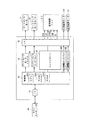
この印刷装置内には、自身を制御するための制御装置が設けられている。この制御装置は、例えば図2に示すように、例えばパーソナルコンピュータ、デジタルカメラ等のホストコンピュータ60から入力された印刷データに基づいて、印刷装置や給紙装置等を制御することにより印刷媒体に印刷処理を行うものである。そして、ホストコンピュータ60から入力された印刷データを受取るための入力インタフェース61と、この入力インタフェース61から入力された印刷データに基づいて印刷処理を実行する例えばマイクロコンピュータで構成される制御部62と、ゲートローラモータ17を駆動制御するゲートローラモータドライバ63と、ピックアップローラ16を駆動するためのピックアップローラモータ51を駆動制御するピックアップローラモータドライバ64と、液体噴射ヘッド2,3を駆動制御するヘッドドライバ65と、右側電動モータ11Rを駆動制御する右側電動モータドライバ66Rと、左側電動モータ11Lを駆動制御する左側電動モータドライバ66Lと、各ドライバ63〜65、66R、66Lと外部のゲートローラモータ17、ピックアップローラモータ51、液体噴射ヘッド2,3、右側電動モータ11R、左側電動モータ11Lとを接続するインタフェース67とを備えて構成される。
A control device for controlling itself is provided in the printing apparatus. For example, as shown in FIG. 2, the control device prints on a print medium by controlling a printing device, a paper feeding device, and the like based on print data input from a
制御部62は、印刷処理等の各種処理を実行するCPU(Central Processing Unit)62aと、入力インタフェース61を介して入力された印刷データ或いは当該印刷データ印刷処理等を実行する際の各種データを一時的に格納し、或いは印刷処理等のプログラムを一時的に展開するRAM(Random Access Memory)62cと、CPU62aで実行する制御プログラム等を格納する不揮発性半導体メモリで構成されるROM(Read-Only Memory)62dを備えている。この制御部62は、インタフェース部61を介してホストコンピュータ60から印刷データ(画像データ)を入手すると、CPU62aが、この印刷データに所定の処理を実行して、何れのノズルから液滴を吐出するか或いはどの程度の液滴を吐出するかというノズル選択データやノズルアクチュエータへの駆動信号出力データを算出し、この印刷データや駆動信号出力データ及び各種センサからの入力データに基づいて、各ドライバ63〜65、66R、66Lに制御信号を出力する。各ドライバ63〜65、66R、66Lからはアクチュエータを駆動するための駆動信号が出力され、液体噴射ヘッド2,3の複数のノズルに対応するノズルアクチュエータ、ゲートローラモータ17、ピックアップローラモータ51、右側電動モータ11R、左側電動モータ11Lが夫々作動して、印刷媒体1の給紙及び搬送、印刷媒体1の姿勢制御、並びに印刷媒体1への印刷処理が実行される。なお、制御部62内の各構成要素は、図示しないバスを介して電気的に接続されている。
The
図3には、本実施形態の印刷装置の制御装置から液体噴射装置2、3に供給され、圧電素子からなるノズルアクチュエータを駆動するための駆動信号COMの一例を示す。本実施形態では、中間電位を中心に電位が変化する信号とした。この駆動信号COMは、ノズルアクチュエータを駆動して液体を噴射する単位駆動信号としての駆動パルスPCOMを時系列的に接続したものであり、各駆動パルスPCOMの立上がり部分がノズルに連通するキャビティ(圧力室)の容積を拡大して液体を引込む(液体の噴射面を考えればメニスカスを引き込むとも言える)段階であり、駆動パルスPCOMの立下がり部分がキャビティの容積を縮小して液体を押出す(液体の噴射面を考えればメニスカスを押出すとも言える)段階であり、液体を押出した結果、液滴がノズルから噴射される。
FIG. 3 shows an example of a drive signal COM that is supplied from the control device of the printing apparatus of the present embodiment to the
この電圧台形波からなる駆動パルスPCOMの電圧増減傾きや波高値を種々に変更することにより、液体の引込量や引込速度、液体の押出量や押出速度を変化させることができ、これにより液滴の噴射量を変化させて異なる大きさのドットを得ることができる。従って、複数の駆動パルスPCOMを時系列的に連結する場合でも、そのうちから単独の駆動パルスPCOMを選択してアクチュエータに供給し、液滴を噴射したり、複数の駆動パルスPCOMを選択してアクチュエータに供給し、液滴を複数回噴射したりすることで種々の大きさのドットを得ることができる。即ち、液体が乾かないうちに複数の液滴を同じ位置に着弾すると、実質的に大きな液滴を噴射するのと同じことになり、ドットの大きさを大きくすることができるのである。このような技術の組合せによって多階調化を図ることが可能となる。なお、図3の左端の駆動信号COMは、液体を引込むだけで押出していない。これは、微振動と呼ばれ、液滴を噴射せずに、例えばノズルの増粘を抑制防止したりするのに用いられる。 By variously changing the voltage increase / decrease slope and peak value of the driving pulse PCOM composed of this voltage trapezoidal wave, the liquid drawing amount and drawing speed, the liquid pushing amount and the pushing speed can be changed. It is possible to obtain dots of different sizes by changing the amount of injection. Therefore, even when a plurality of drive pulses PCOM are connected in time series, a single drive pulse PCOM is selected and supplied to the actuator, and droplets are ejected or a plurality of drive pulses PCOM are selected and the actuator is selected. In this way, dots of various sizes can be obtained by ejecting droplets a plurality of times. That is, if a plurality of droplets land on the same position before the liquid dries, it is substantially the same as ejecting a large droplet, and the size of the dot can be increased. By combining such techniques, it is possible to increase the number of gradations. Note that the drive signal COM at the left end in FIG. 3 only draws liquid and does not push it out. This is called microvibration, and is used, for example, to suppress or prevent thickening of the nozzle without ejecting droplets.
これらの結果、液体噴射ヘッド2,3には、後述する駆動信号出力回路から出力される駆動信号COM、印刷データに基づいて噴射するノズルを選択すると共に圧電素子などのノズルアクチュエータの駆動信号COMへの接続タイミングを決定する駆動信号選択データSI&SP、全ノズルにノズル選択データが入力された後、駆動信号選択データSI&SPに基づいて駆動信号COMと液体噴射ヘッド2,3のノズルアクチュエータとを接続させるラッチ信号LAT及びチャンネル信号CH、駆動信号選択データSI&SPをシリアル信号として液体噴射ヘッド2,3に送信するためのクロック信号SCKが入力されている。なお、これ以後、ノズルアクチュエータを駆動する駆動信号の最小単位を駆動パルスPCOMとし、駆動パルスPCOMが時系列的に連結された信号全体を駆動信号COMと記す。 As a result, the liquid ejecting heads 2 and 3 select the nozzles to be ejected based on the drive signal COM output from the drive signal output circuit, which will be described later, and the print data, and the drive signals COM of the nozzle actuators such as piezoelectric elements. Drive signal selection data SI & SP for determining the connection timing of the nozzles, and after the nozzle selection data is inputted to all nozzles, the latch for connecting the drive signal COM and the nozzle actuators of the liquid jet heads 2 and 3 based on the drive signal selection data SI & SP A clock signal SCK for transmitting the signal LAT, the channel signal CH, and the drive signal selection data SI & SP as serial signals to the liquid jet heads 2 and 3 is input. Hereinafter, the minimum unit of the drive signal for driving the nozzle actuator is referred to as a drive pulse PCOM, and the entire signal in which the drive pulses PCOM are connected in time series is referred to as a drive signal COM.
次に、前記駆動回路から出力される駆動信号COMと圧電素子などのノズルアクチュエータを接続する構成について説明する。図4は、駆動信号COMとピエゾ素子などのアクチュエータとを接続する選択部のブロック図である。この選択部は、インク滴を吐出させるべきノズルに対応した圧電素子などのノズルアクチュエータを指定するための駆動信号選択データSI&SPを保存するシフトレジスタ211と、シフトレジスタ211のデータを一時的に保存するラッチ回路212と、ラッチ回路212の出力をレベル変換するレベルシフタ213と、レベルシフタの出力に応じて駆動信号COMをピエゾ素子などのノズルアクチュエータ22に接続する選択スイッチ201によって構成されている。
Next, a configuration for connecting a drive signal COM output from the drive circuit and a nozzle actuator such as a piezoelectric element will be described. FIG. 4 is a block diagram of a selection unit that connects the drive signal COM and an actuator such as a piezo element. This selection unit temporarily stores drive register selection data SI & SP for designating a nozzle actuator such as a piezoelectric element corresponding to a nozzle that should eject ink droplets, and data in the
シフトレジスタ211には、駆動信号選択データ信号SI&SPが順次入力されると共に、クロック信号SCKの入力パルスに応じて記憶領域が初段から順次後段にシフトする。ラッチ回路212は、ノズル数分の駆動信号選択データSI&SPがシフトレジスタ211に格納された後、入力されるラッチ信号LATによってシフトレジスタ211の各出力信号をラッチする。ラッチ回路212に保存された信号は、レベルシフタ213によって次段の選択スイッチ201をオンオフできる電圧レベルに変換される。これは、駆動信号COMが、ラッチ回路212の出力電圧に比べて高い電圧であり、これに合わせて選択スイッチ201の動作電圧範囲も高く設定されているためである。従って、レベルシフタ213によって選択スイッチ201が閉じられる圧電素子などのノズルアクチュエータは駆動信号選択データSI&SPの接続タイミングで駆動信号COM(駆動パルスPCOM)に接続される。また、シフトレジスタ211の駆動信号選択データSI&SPがラッチ回路212に保存された後、次の印字情報をシフトレジスタ211に入力し、インク滴の吐出タイミングに合わせてラッチ回路212の保存データを順次更新する。なお、図中の符号HGNDは、圧電素子などのノズルアクチュエータのグランド端である。また、この選択スイッチ201によれば、圧電素子などのノズルアクチュエータを駆動信号COM(駆動パルスPCOM)から切り離した後も、当該ノズルアクチュエータ22の入力電圧は、切り離す直前の電圧に維持される。
The drive signal selection data signal SI & SP is sequentially input to the
図5には、ノズルアクチュエータ22を駆動するヘッドドライバ65内の駆動信号出力回路の具体的な構成の一例を示す。ラインヘッド型印刷装置を構成する液体噴射ヘッド2,3には多数のノズルが形成されており、その夫々に、前述したノズルアクチュエータ22が設けられている。これらのノズルアクチュエータ22の上流側には、夫々、トランスミッションゲートで構成される選択スイッチ23が配設されており、各選択スイッチ23は図示しないノズル選択制御回路により印刷データに応じてオンオフされ、選択スイッチ23がオンされているノズルアクチュエータ22にのみ駆動信号COM(駆動パルスPCOM)が印加される。
FIG. 5 shows an example of a specific configuration of a drive signal output circuit in the
一方、駆動信号出力回路は、制御部62からの駆動信号出力データに基づいて、駆動信号COM(駆動パルスPCOM)の元、つまりノズルアクチュエータ22の駆動を制御する信号の基準となる駆動波形信号WCOMを生成する駆動波形信号発生回路25と、駆動波形信号発生回路25で生成された駆動波形信号WCOMをパルス変調する変調回路26と、変調回路26でパルス変調された変調信号を電力増幅するデジタル電力増幅器、所謂D級アンプ28と、デジタル電力増幅器28で電力増幅された電力増幅変調信号を平滑化して、駆動信号COM(駆動パルスPCOM)としてノズルアクチュエータ22に供給する第1平滑フィルタ29a及び第2平滑フィルタ29bとを備えて構成される。
On the other hand, the drive signal output circuit is based on the drive signal output data from the
駆動波形信号発生回路25は、予め設定されたデジタルデータを時系列に組合せて出力し、それをD/A変換器でアナログ変換して駆動波形信号WCOMとして出力する。本実施形態では、この駆動波形信号WCOMをパルス変調する変調回路26に、一般的なパルス幅変調(PWM)回路を用いた。パルス幅変調は、三角波信号発生回路23で所定周波数の三角波信号を発生し、この三角波信号と駆動波形信号WCOMとをコンパレータ24で比較して、例えば三角波信号より駆動波形信号WCOMが大きいときにオンデューティとなるパルス信号を変調信号として出力する。デジタル電力増幅器28は、実質的に電力を増幅するためのハイサイドのスイッチング素子Q1及びローサイドのスイッチング素子Q2からなるハーフブリッジD級出力段31と、変調回路26からの変調信号に基づいて、それらのスイッチング素子Q1、Q2のゲート−ソース間信号GH、GLを調整するためのゲートドライバ回路30とを備えて構成されている。また、第1平滑フィルタ29aはコイルLとコンデンサCの組合せからなるローパスフィルタ(低域通過フィルタ)で構成され、このローパスフィルタによって電力増幅変調信号の変調周期成分、この場合は三角波信号の周波数成分が除去される。つまり、第1平滑フィルタ29aは、デジタル電力増幅器28の出力特性に対応づけて設けられている。また、第2平滑フィルタ29bは各ノズルアクチュエータ22との間に介装された抵抗Rを当該ノズルアクチュエータ22の数分だけ備えて構成され、この抵抗Rとノズルアクチュエータ22の静電容量でローパスフィルタ(低域通過フィルタ)が構成される。つまり、ノズルアクチュエータ22分だけローパスフィルタが設けられていることになり、ノズルアクチュエータ22がオンされるたびにローパスフィルタが駆動信号出力回路に接続されることになる。従って、第2平滑フィルタ29bは、各ノズルアクチュエータ22の周波数特性に対応づけて設けられている。
The drive waveform
デジタル電力増幅器28では、変調信号がHiレベルであるとき、ハイサイド側スイッチング素子Q1のゲート−ソース間信号GHはHiレベルとなり、ローサイド側スイッチング素子Q2のゲート−ソース間信号GLはLoレベルとなるので、ハイサイド側スイッチング素子Q1はON状態となり、ローサイド側スイッチング素子Q2はOFF状態となり、その結果、ハーフブリッジD級出力段31の出力は、供給電力VDDとなる。一方、変調信号がLoレベルであるとき、ハイサイド側スイッチング素子Q1のゲート−ソース間信号GHはLoレベルとなり、ローサイド側スイッチング素子Q2のゲート−ソース間信号GLはHiレベルとなるので、ハイサイド側スイッチング素子Q1はOFF状態となり、ローサイド側スイッチング素子Q2はON状態となり、その結果、ハーフブリッジ出力段31の出力は0となる。
In the
このようにハイサイド及びローサイドのスイッチング素子がデジタル駆動される場合には、ON状態のスイッチング素子に電流が流れるが、ドレイン−ソース間の抵抗値は非常に小さく、損失は殆ど発生しない。また、OFF状態のスイッチング素子には電流が流れないので損失は発生しない。従って、このデジタル電力増幅器28の損失は極めて小さく、小型のMOSFET等のスイッチング素子を使用することができ、冷却用放熱板などの冷却手段も不要である。ちなみに、トランジスタをリニア駆動するときの効率が30%程度であるのに対し、デジタル電力増幅器の効率は90%以上である。また、トランジスタの冷却用放熱板は、トランジスタ一つに対して60mm角程度の大きさが必要になるので、こうした冷却用放熱板が不要になると、実際のレイアウト面で圧倒的に有利である。
In this way, when the high-side and low-side switching elements are digitally driven, a current flows through the ON-state switching elements, but the resistance value between the drain and source is very small and almost no loss occurs. In addition, since no current flows through the switching element in the OFF state, no loss occurs. Therefore, the loss of the
図6には、本実施形態の駆動信号出力回路全体の周波数特性を示す。図中のゲインの平坦な領域が駆動波形信号の周波数成分であり、駆動信号COM(駆動パルスPCOM)に反映すべき周波数成分である。また、図中のゲインの低減する領域がパルス変調の変調周期、即ち三角波信号発生回路23から発生される三角波信号の周期に相当する周波数成分であり、駆動信号COM(駆動パルスPCOM)に反映すべきでない周波数成分である。本実施形態では、各ノズルアクチュエータ22の静電容量と各ノズルアクチュエータ22に接続されている第2平滑フィルタ29bの抵抗Rによってローパスフィルタが構成されているため、ノズルアクチュエータ22をオンするとそれに伴ってローパスフィルタが駆動信号出力回路に接続されることになるため、オンされるノズルアクチュエータ22の数が多い場合(図中の負荷大)でも、オンされるノズルアクチュエータ22の数が少ない場合(図中の負荷小)でも、周波数特性は大きく変化していない。即ち、オンされるノズルアクチュエータ22の数に関わらず、駆動信号出力回路全体の周波数特性は余り変化せず、その結果、ノズルアクチュエータ22の夫々にダミー静電容量を併設する場合のように消費電力を増大することなく、駆動信号COM(駆動パルスPCOM)の特性変化を抑制防止することができる。また、コイルLやコンデンサCで構成される第1平滑フィルタ29aをデジタル電力増幅器28側に一つだけ配設することで、電力増幅変調信号の変調周期成分を効率よく除去することができると共に、容積の大きなコイルやコンデンサが少数ですむため、回路構成を簡素化し、回路面積を低減することが可能となる。
FIG. 6 shows the frequency characteristics of the entire drive signal output circuit of this embodiment. The flat region of the gain in the figure is the frequency component of the drive waveform signal, and is the frequency component that should be reflected in the drive signal COM (drive pulse PCOM). Further, the gain reduction region in the figure is a frequency component corresponding to the modulation period of pulse modulation, that is, the period of the triangular wave signal generated from the triangular wave
図7は、平滑フィルタをコイルL、コンデンサC、抵抗Rで構成される一般的な一次ローパスフィルタとし、その平滑フィルタをノズルアクチュエータ22と図示しないデジタル電力増幅器の間に一つだけ介装した従来の駆動信号出力回路の出力部分のブロック図である。図8には、この従来技術の駆動信号出力回路全体の周波数特性を示す。このような構成では、ノズルアクチュエータ22をオンするたびに平滑フィルタにノズルアクチュエータ22の静電容量が付加され、ローパスフィルタの周波数特性が変化してしまう。例えば、この比較例では、オンされるノズルアクチュエータ22の数が多いほど(図中の負荷大)、ゲインが増大する傾向にあり、オンされるノズルアクチュエータ22の数が少ないほど(図中の負荷小)、ゲインが減少する傾向にある。例えばゲインが増大すると、除去すべきパルス変調の周波数成分が残存して駆動信号COM(駆動パルスPCOM)が変化するし、ゲインが減少すると、反映すべき駆動波形信号WCOMの周波数成分が低減して駆動信号COM(駆動パルスPCOM)が変化する。
In FIG. 7, the smoothing filter is a general primary low-pass filter composed of a coil L, a capacitor C, and a resistor R, and only one smoothing filter is interposed between the
このように本実施形態の液体噴射装置によれば、ノズルアクチュエータ22を駆動するための基準となる駆動波形信号WCOMを駆動波形信号発生回路25で発生し、その駆動波形信号WCOMを変調回路26でパルス変調し、そのパルス変調された変調信号をデジタル電力増幅器28のプッシュプル接続されたスイッチング素子対により電力増幅し、その電力増幅された電力増幅変調信号を第1平滑フィルタ29a及び第2平滑フィルタ29bで平滑化してノズルアクチュエータ22に向けて出力するにあたり、各アクチュエータ22毎に第2平滑フィルタ29bを設けることで静電容量変動に対する平滑フィルタ全体のゲインの変動を抑制することができ、これにより消費電力を増大することなく、駆動信号COM(駆動パルスPCOM)の特性変化を抑制防止することができると共に、デジタル電力増幅側に共通の第1平滑フィルタ29aを設けることで回路構成を簡素化することができる。
As described above, according to the liquid ejecting apparatus of the present embodiment, the drive waveform signal WCOM serving as a reference for driving the
また、第1平滑フィルタ29aはデジタル電力増幅器28の特性に対応づけて設け、前記第2平滑フィルタは前記複数のアクチュエータの夫々の特性に対応づけて設けたことにより、電力増幅変調信号の変調周期成分を効率よく除去することができると共に、駆動信号COM(駆動パルスPCOM)の特性変化を効率よく抑制防止することができる。
また、第1平滑フィルタ29aは、コイルLとコンデンサCで構成したことにより、電力増幅変調信号の変調周期成分を効率よく除去することができると共に、容積の大きなコイルLやコンデンサCが少数ですむため、回路構成を簡素化し、回路面積を低減することが可能となる。
Further, the first smoothing
In addition, since the first smoothing
また、第2平滑フィルタ29bは、ノズルアクチュエータ22の静電容量を含めた低域通過フィルタ(ローパスフィルタ)であることとしたため、個々のノズルアクチュエータ22に低域通過フィルタ(ローパスフィルタ)が設けられていることになり、第1平滑フィルタ29aとで構成される低域通過フィルタ(ローパスフィルタ)の静電容量が単純に増減する場合に比べて、駆動信号COM(駆動パルスPCOM)の特性変化を効率よく抑制防止することができる。
また、第2平滑フィルタ29は、ノズルアクチュエータ22の静電容量と各アクチュエータ22の特性に対応づけて設けられた抵抗Rにより低域通過フィルタ(ローパスフィルタ)を構成することとしたため、回路構成を簡素化し、回路面積を低減することができる。
Since the
Further, since the second smoothing filter 29 is configured as a low-pass filter (low-pass filter) by the resistance R provided in correspondence with the capacitance of the
次に、本発明の液体噴射装置をラインヘッド型印刷装置に適用した第2実施形態について説明する。図9は、本実施形態の駆動信号出力回路のブロック図である。本実施形態の駆動信号出力回路は、前記図5の第1実施形態の駆動信号出力回路に類似しており、同等の構成要件も多い。そこで、同等の構成要件には同等の符号を附して、その詳細な説明を省略する。具体的には、両者に存在する回路の構成要件は全て同じであり、変調回路26と駆動波形信号発生回路25の間に逆フィルタ32が介装され、この逆フィルタ32のフィルタ特性を印刷データに応じて変更する逆フィルタ特性変更回路33が付加されている。
Next, a second embodiment in which the liquid ejecting apparatus of the present invention is applied to a line head type printing apparatus will be described. FIG. 9 is a block diagram of the drive signal output circuit of this embodiment. The drive signal output circuit according to the present embodiment is similar to the drive signal output circuit according to the first embodiment shown in FIG. 5 and has many equivalent components. Therefore, equivalent constituent elements are denoted by the same reference numerals, and detailed description thereof is omitted. Specifically, the circuit configuration requirements of both are the same, and an
逆フィルタ32は、第1平滑フィルタ29a及び第2平滑フィルタ29b及びノズルアクチュエータ22で構成されるローパスフィルタ(低域通過フィルタ)のフィルタ特性と逆のフィルタ特性を有するものであり、前述のようにオンされるノズルアクチュエータ22の数によってローパスフィルタ(低域通過フィルタ)のフィルタ特性が異なることから、当該オンされるノズルアクチュエータ22の数に応じたローパスフィルタのフィルタ特性と逆のフィルタ特性を幾つか記憶している。本実施形態では、特に駆動波形信号の周波数成分が安定して出力されるフィルタ特性とした。
The
逆フィルタ特性変更回路33は、印刷データからオンされるノズルアクチュエータ22の数を算出し、そのオンされるノズルアクチュエータ22の数に応じて逆フィルタ32のフィルタ特性を変更するものであり、例えば本実施形態のように、逆フィルタ32がオンされるノズルアクチュエータ22の数に応じたローパスフィルタのフィルタ特性と逆のフィルタ特性を幾つか備えている場合には、オンされるノズルアクチュエータ22の数に応じた逆フィルタ特性を選出する。本実施形態の場合、オンされるノズルアクチュエータ22の数は駆動パルスPCOM毎に変化するので、オンされるノズルアクチュエータ22の数に応じた逆フィルタ特性の選出は、各駆動パルスPCOMの間(繋ぎ目)で行われる。
The inverse filter characteristic changing
この駆動信号出力回路全体の周波数特性を図10及び図11示す。図10は、オンされるノズルアクチュエータ22の数が少ない場合(図中の負荷小)の周波数特性、図11は、オンされるノズルアクチュエータ22の数が多い場合(図中の負荷大)の周波数特性を示す。本実施形態では、前述したように逆フィルタ32に記憶させるフィルタ特性を、駆動波形信号の周波数成分が安定して出力されるものとしたため、例えばオンされるノズルアクチュエータ22の数が少ない場合には駆動波形信号の周波数成分を減少させるような逆フィルタ32のフィルタ特性が記憶され、オンされるノズルアクチュエータ22の数が多い場合には駆動波形信号の周波数成分を増大させるような逆フィルタ32のフィルタ特性が記憶されている。そのため、これらのフィルタ特性が選出された駆動信号出力回路では、駆動波形信号の周波数成分が安定して出力され、駆動信号COM(駆動パルスPCOM)の駆動信号COM(駆動パルスPCOM)の特性変化をより一層抑制防止することができる。
The frequency characteristics of the entire drive signal output circuit are shown in FIGS. FIG. 10 shows the frequency characteristics when the number of
このように本実施形態の液体噴射装置によれば、前記第1実施形態の効果に加えて、第1平滑フィルタ29a及び第2平滑フィルタ29b及びノズルアクチュエータ22のフィルタ特性と逆のフィルタ特性を有する逆フィルタ32と、駆動信号COM(駆動パルスPCOM)が印加されるノズルアクチュエータ22の数に応じて逆フィルタ32のフィルタ特性を変更する逆フィルタ特性変更回路33とを備えたことにより、駆動信号COM(駆動パルスPCOM)の特性変化をより一層抑制防止することができる。
Thus, according to the liquid ejecting apparatus of the present embodiment, in addition to the effects of the first embodiment, the filter characteristics of the first smoothing
なお、前記実施形態では、逆フィルタ32に記憶するフィルタ特性をオンされるノズルアクチュエータ22の数に応じて幾つか記憶するものとしたが、その数は限定されるものではない。また、逆フィルタ32に幾つかのフィルタ特性を記憶する代わりに、逆フィルタ32のフィルタ特性を司るパラメータをオンされるノズルアクチュエータ22の数に応じて逆フィルタ特性変更回路33が変更することで、逆フィルタ32のフィルタ特性が連続的に変化するようにしてもよい。
また、前記実施形態では、本発明の液体噴射装置をラインヘッド型印刷装置に用いた場合についてのみ詳述したが、本発明の液体噴射装置は、マルチパス型印刷装置にも同様に適用可能である。
In the above-described embodiment, several filter characteristics stored in the
In the above-described embodiment, only the case where the liquid ejecting apparatus of the present invention is used in a line head type printing apparatus has been described in detail. However, the liquid ejecting apparatus of the present invention can be similarly applied to a multi-pass type printing apparatus. is there.
また、前記実施形態では、本発明の液体噴射装置をインクジェット式印刷装置に具体化したが、この限りではなく、インク以外の他の液体(液体以外にも、機能材料の粒子が分散されている液状体、ジェルなどの流状体を含む)や液体以外の流体(流体として流して噴射できる固体など)を噴射したり吐出したりする液体噴射装置に具体化することもできる。例えば、液晶ディスプレイ、EL(エレクトロルミネッサンス)ディスプレイ、面発光ディスプレイ、カラーフィルタの製造などに用いられる電極材や色材などの材料を分散又は溶解の形態で含む液状体を噴射する液状体噴射装置、バイオチップ製造に用いられる生体有機物を噴射する液体噴射装置、精密ピペットとして用いられて試料となる液体を噴射する液体噴射装置であってもよい。更に、時計やカメラなどの精密機械にピンポイントで潤滑油を噴射する液体噴射装置、光通信素子などに用いられる微小半球レンズ(光学レンズ)などを形成するための紫外線硬化樹脂などの透明樹脂液を基板上に吐出する液体噴射装置、基板などをエッチングするために酸又はアルカリなどのエッチング液を噴射する液体噴射装置、ジェルを噴射する流状体噴射装置、トナーなどの粉体を例とする固体を噴射する流体噴射式記録装置であってもよい。そして、これらのうち何れか一種の噴射装置に本発明を適用することができる。 In the above embodiment, the liquid ejecting apparatus of the present invention is embodied in an ink jet printing apparatus. However, the present invention is not limited to this, and liquids other than ink (functional material particles are dispersed in addition to liquids). It is also possible to embody the present invention in a liquid ejecting apparatus that ejects or ejects a fluid other than a liquid (including a fluid such as a liquid or gel) or a fluid other than a liquid (such as a solid that can be ejected by flowing as a fluid). For example, a liquid material ejecting apparatus that ejects a liquid material that contains materials such as electrode materials and color materials used in the manufacture of liquid crystal displays, EL (electroluminescence) displays, surface-emitting displays, color filters, and the like in a dispersed or dissolved form. Further, it may be a liquid ejecting apparatus that ejects a bio-organic matter used for biochip manufacturing, or a liquid ejecting apparatus that ejects a liquid that is used as a precision pipette and serves as a sample. In addition, transparent resin liquids such as UV curable resins for forming liquid injection devices that inject lubricating oil onto precision machines such as watches and cameras, micro hemispherical lenses (optical lenses) used in optical communication elements, etc. For example, a liquid ejecting apparatus that ejects a liquid onto a substrate, a liquid ejecting apparatus that ejects an etching solution such as acid or alkali to etch the substrate, a fluid ejecting apparatus that ejects gel, and a powder such as toner It may be a fluid ejection recording apparatus that ejects a solid. The present invention can be applied to any one of these injection devices.
1は印刷媒体、2,3は液体噴射ヘッド、4,5は搬送部、23は三角波信号発生回路、24はコンパレータ、25は駆動波形信号発生回路、26は変調回路、27は変調周期調整回路、28はデジタル電力増幅器、29は平滑フィルタ、30はゲートドライバ回路、31はハーフブリッジ出力段、32は逆フィルタ、33は逆フィルタ特性変更回路、62は制御部、65はヘッドドライバ 1 is a printing medium, 2 and 3 are liquid ejecting heads, 4 and 5 are conveyance units, 23 is a triangular wave signal generation circuit, 24 is a comparator, 25 is a drive waveform signal generation circuit, 26 is a modulation circuit, and 27 is a modulation cycle adjustment circuit. , 28 is a digital power amplifier, 29 is a smoothing filter, 30 is a gate driver circuit, 31 is a half-bridge output stage, 32 is an inverse filter, 33 is an inverse filter characteristic changing circuit, 62 is a control unit, and 65 is a head driver.
Claims (7)
前記駆動波形信号発生回路で発生された駆動波形信号をパルス変調する変調回路と、
プッシュプル接続されたスイッチング素子対により前記変調回路でパルス変調された変調信号を電力増幅するデジタル電力増幅器と、
前記デジタル電力増幅器で電力増幅された電力増幅変調信号を平滑化する第1平滑フィルタと、
前記複数のアクチュエータの夫々に設けられ、前記第1平滑フィルタの出力をさらに平滑化し、前記アクチュエータに向けて駆動信号を出力する第2平滑フィルタと、
を備えたことを特徴とする液体噴射装置。 A drive waveform signal generating circuit that generates a drive waveform signal that serves as a reference for driving a plurality of actuators for liquid ejection;
A modulation circuit for pulse-modulating the drive waveform signal generated by the drive waveform signal generation circuit;
A digital power amplifier that amplifies the power of a modulation signal pulse-modulated by the modulation circuit by a pair of push-pull connected switching elements;
A first smoothing filter for smoothing the power amplification modulated signal that has been power amplified by the digital power amplifier ;
A second smoothing filter that is provided in each of the plurality of actuators, further smoothes the output of the first smoothing filter, and outputs a drive signal toward the actuator;
A liquid ejecting apparatus comprising the.
Priority Applications (1)
| Application Number | Priority Date | Filing Date | Title |
|---|---|---|---|
| JP2007337473A JP5115187B2 (en) | 2007-12-27 | 2007-12-27 | Liquid ejector |
Applications Claiming Priority (1)
| Application Number | Priority Date | Filing Date | Title |
|---|---|---|---|
| JP2007337473A JP5115187B2 (en) | 2007-12-27 | 2007-12-27 | Liquid ejector |
Publications (3)
| Publication Number | Publication Date |
|---|---|
| JP2009154478A JP2009154478A (en) | 2009-07-16 |
| JP2009154478A5 JP2009154478A5 (en) | 2011-01-06 |
| JP5115187B2 true JP5115187B2 (en) | 2013-01-09 |
Family
ID=40958997
Family Applications (1)
| Application Number | Title | Priority Date | Filing Date |
|---|---|---|---|
| JP2007337473A Active JP5115187B2 (en) | 2007-12-27 | 2007-12-27 | Liquid ejector |
Country Status (1)
| Country | Link |
|---|---|
| JP (1) | JP5115187B2 (en) |
Families Citing this family (5)
| Publication number | Priority date | Publication date | Assignee | Title |
|---|---|---|---|---|
| JP5212336B2 (en) | 2009-10-29 | 2013-06-19 | セイコーエプソン株式会社 | Liquid ejecting apparatus, liquid ejecting printing apparatus, and driving method of liquid ejecting apparatus |
| JP5471325B2 (en) * | 2009-11-10 | 2014-04-16 | セイコーエプソン株式会社 | Liquid ejecting apparatus, printing apparatus, and surgical tool |
| JP5736645B2 (en) * | 2010-01-15 | 2015-06-17 | 株式会社リコー | Recording head drive device |
| JP6007512B2 (en) * | 2012-02-29 | 2016-10-12 | セイコーエプソン株式会社 | Liquid discharge head drive circuit |
| JP6020806B2 (en) * | 2012-09-06 | 2016-11-02 | セイコーエプソン株式会社 | Liquid ejecting apparatus and printing apparatus |
Family Cites Families (4)
| Publication number | Priority date | Publication date | Assignee | Title |
|---|---|---|---|---|
| JP2007168172A (en) * | 2005-12-20 | 2007-07-05 | Seiko Epson Corp | Head drive device for inkjet printer |
| CN101370662B (en) * | 2006-01-17 | 2010-08-25 | 精工爱普生株式会社 | Head drive device of inkjet printer and ink jet printer |
| JP2007203493A (en) * | 2006-01-31 | 2007-08-16 | Seiko Epson Corp | Inkjet printer |
| JP4946685B2 (en) * | 2006-07-24 | 2012-06-06 | セイコーエプソン株式会社 | Liquid ejecting apparatus and printing apparatus |
-
2007
- 2007-12-27 JP JP2007337473A patent/JP5115187B2/en active Active
Also Published As
| Publication number | Publication date |
|---|---|
| JP2009154478A (en) | 2009-07-16 |
Similar Documents
| Publication | Publication Date | Title |
|---|---|---|
| JP5145921B2 (en) | Liquid ejector | |
| JP4518152B2 (en) | Liquid ejecting apparatus and ink jet printer | |
| JP5256713B2 (en) | Capacitive load driving circuit, liquid ejecting apparatus, and printing apparatus | |
| JP5109651B2 (en) | Liquid ejecting apparatus and printing apparatus | |
| JP4877234B2 (en) | Inkjet printer head drive device and inkjet printer | |
| JP4992723B2 (en) | Inkjet printer head drive apparatus and drive control method, and inkjet printer | |
| US7984956B2 (en) | Liquid jet apparatus and printing apparatus | |
| JP4333753B2 (en) | Inkjet printer | |
| US8336979B2 (en) | Liquid jetting device | |
| JP5170211B2 (en) | Capacitive load drive circuit, jetting apparatus and printing apparatus | |
| JP5256768B2 (en) | Liquid ejector | |
| JPWO2007086375A1 (en) | Inkjet printer head drive apparatus, head drive method, and inkjet printer | |
| JP2007168172A (en) | Head drive device for inkjet printer | |
| JP2012011782A (en) | Head driving device of ink jet printer, and ink jet printer | |
| JP5115187B2 (en) | Liquid ejector | |
| JP5287618B2 (en) | Liquid ejecting apparatus and printing apparatus | |
| JP5783203B2 (en) | Liquid ejecting apparatus, printing apparatus, and driving method of liquid ejecting apparatus | |
| JP5440684B2 (en) | Driving circuit | |
| JP2009286134A (en) | Liquid jet device and printing device | |
| JP2009226628A (en) | Liquid jetting device | |
| JP2009226901A (en) | Liquid jet device |
Legal Events
| Date | Code | Title | Description |
|---|---|---|---|
| A521 | Written amendment |
Free format text: JAPANESE INTERMEDIATE CODE: A523 Effective date: 20101116 |
|
| A621 | Written request for application examination |
Free format text: JAPANESE INTERMEDIATE CODE: A621 Effective date: 20101116 |
|
| RD04 | Notification of resignation of power of attorney |
Free format text: JAPANESE INTERMEDIATE CODE: A7424 Effective date: 20110630 |
|
| A977 | Report on retrieval |
Free format text: JAPANESE INTERMEDIATE CODE: A971007 Effective date: 20120912 |
|
| TRDD | Decision of grant or rejection written | ||
| A01 | Written decision to grant a patent or to grant a registration (utility model) |
Free format text: JAPANESE INTERMEDIATE CODE: A01 Effective date: 20120918 |
|
| A01 | Written decision to grant a patent or to grant a registration (utility model) |
Free format text: JAPANESE INTERMEDIATE CODE: A01 |
|
| A61 | First payment of annual fees (during grant procedure) |
Free format text: JAPANESE INTERMEDIATE CODE: A61 Effective date: 20121001 |
|
| R150 | Certificate of patent or registration of utility model |
Free format text: JAPANESE INTERMEDIATE CODE: R150 Ref document number: 5115187 Country of ref document: JP Free format text: JAPANESE INTERMEDIATE CODE: R150 |
|
| FPAY | Renewal fee payment (event date is renewal date of database) |
Free format text: PAYMENT UNTIL: 20151026 Year of fee payment: 3 |
|
| S531 | Written request for registration of change of domicile |
Free format text: JAPANESE INTERMEDIATE CODE: R313531 |
|
| R350 | Written notification of registration of transfer |
Free format text: JAPANESE INTERMEDIATE CODE: R350 |