JP5114590B2 - Turbine seal structure - Google Patents
Turbine seal structure Download PDFInfo
- Publication number
- JP5114590B2 JP5114590B2 JP2011238242A JP2011238242A JP5114590B2 JP 5114590 B2 JP5114590 B2 JP 5114590B2 JP 2011238242 A JP2011238242 A JP 2011238242A JP 2011238242 A JP2011238242 A JP 2011238242A JP 5114590 B2 JP5114590 B2 JP 5114590B2
- Authority
- JP
- Japan
- Prior art keywords
- turbine
- blade
- shim
- disk
- sealing material
- Prior art date
- Legal status (The legal status is an assumption and is not a legal conclusion. Google has not performed a legal analysis and makes no representation as to the accuracy of the status listed.)
- Active
Links
Images


Landscapes
- Turbine Rotor Nozzle Sealing (AREA)
- Gasket Seals (AREA)
Description
本発明は、例えばガスタービンエンジンにおけるタービンディスクとその外周部に取り付けられる複数のタービン翼との間から冷却媒体が漏れるのを抑制するシール構造に関するものである。 The present invention relates to a seal structure that suppresses leakage of a cooling medium from between a turbine disk in a gas turbine engine, for example, and a plurality of turbine blades attached to the outer periphery thereof.
図5の横断面図に示すように、ガスタービンエンジンにおけるタービン30は、タービンディスク31の外周部に、周方向Qに一定間隔をおいて複数の取付溝33が形成されており、複数のタービン動翼32のそれぞれが、翼部34の下部の翼取付部35を取付溝33に軸方向に挿入して嵌合することで、タービンディスク31に取り付けられている。タービンディスク31の取付溝33とタービン動翼32の翼取付部35とは、周方向Qおよび径方向Rに所要の隙間36を存して嵌合するようになっている。
As shown in the cross-sectional view of FIG. 5, the
また、タービン30には、高温の燃焼ガスに対するタービン動翼32の耐熱性の向上を図るために、冷却媒体である冷却空気Aによりタービン動翼32を冷却する冷却構造が採用されている。この冷却構造は、タービンディスク31の外方からこれの冷却通路31aに導入した冷却空気Aをタービン動翼32の内部の冷却通路32aに供給するようになっている。ところが、タービンディスク31の冷却通路31aの出口部31aaとタービン動翼32の冷却通路32aの入口部32aaとの間に前記隙間36が介在しているため、この隙間36に冷却空気Aの一部が漏れ出て、タービン動翼32の冷却空気Aによる冷却効率が低下する。そこで、従来では、タービンディスク31の取付溝33の溝底面33aとタービン動翼32の翼取付部35の先端面35aとの間に、この両者間の隙間36を埋めて冷却空気Aの漏れを抑制するためのシム材38を介装し、このシム材38に形成された貫通孔38aを通じてタービンディスク31の冷却通路31aとタービン動翼32の冷却通路32aとを互いに気密に連通させている(シムについては特許文献1参照)。
The
しかしながら、前記シール構造では、シム材38の厚みの寸法管理が難しく、シム材38の厚みを隙間36よりも小さ目に設定した場合、タービン回転時の遠心力を受けてシム材38が翼取付部35の先端面35aに張り付く状態に接触して、シム材38とタービンディスク31の取付溝33との間に空隙が生じ、シール性が低下する。そこで、隙間36とほぼ同じ厚みに設定したシム材38を隙間36に圧入するようにしているが、この場合、シム材38を軸方向から叩打しながら隙間36内に強制的に押し込む作業を行うことから、組立性が悪いだけでなく、シム材38の一部が曲がったり、シム材38における貫通孔38aの孔縁部がタービン動翼32の冷却通路32aの入口部32aaの一部を塞ぐ状態に位置ずれすることがある。
However, in the seal structure, it is difficult to manage the thickness of the
また、冷却空気Aによる冷却効果と組立性の双方の向上を考慮すると、シム材38の厚みを所定寸法に高精度に加工する必要があるのに伴ってコスト高を招く。さらに、タービンディスク31およびタービン動翼32の形状公差などによって隙間36の大きさにばらつきが生じるのに伴って冷却空気Aの漏れ量、つまりタービン動翼32への冷却空気量にもばらつきが生じる。また、シム材38の隙間36への挿入方向(軸方向)に対するシム材38の抜け止め機構が必要である。
In consideration of both the cooling effect by the cooling air A and the improvement of the assemblability, the thickness of the
本発明は、簡単で安価な構成としながらも、冷却媒体の漏れを効果的に抑制して冷却効果の向上を図ることができるタービンのシール構造を提供することを目的とする。 SUMMARY OF THE INVENTION An object of the present invention is to provide a turbine seal structure capable of effectively suppressing leakage of a cooling medium and improving the cooling effect while having a simple and inexpensive configuration.
上記目的を達成するために、本発明の一構成に係るタービンのシール構造は、タービンディスクとその外周部に取り付けられる複数のタービン翼との間で、冷却媒体の漏れを抑制するタービンのシール構造であって、前記各タービン翼の翼取付部が前記タービンディスクにおける取付溝に径方向と直交する方向への嵌合により取り付けられ、前記タービンディスクおよびタービン翼に、冷却媒体を前記タービンディスクの外方から内方を経て前記タービン翼内に導入する冷却通路が形成されており、前記タービン翼の前記翼取付部と前記タービンディスクの取付溝との間の隙間にシム材が挿入され、前記シム材に前記冷却通路の一部を形成する貫通孔を有するシール材が取り付けられ、前記タービンディスクに前記シール材が嵌合される嵌合孔が設けられ、前記シール材の外周面と前記嵌合孔の内周面との間が気密となるように前記シール材が前記嵌合孔に緊密に嵌合され、前記シム材が帯状であり、遠心力により前記タービン翼の前記翼取付部に押し付けられて接触して前記翼取付部との間をシールしている。 In order to achieve the above object, a turbine seal structure according to one configuration of the present invention is a turbine seal structure that suppresses leakage of a cooling medium between a turbine disk and a plurality of turbine blades attached to the outer periphery thereof. The blade mounting portion of each turbine blade is attached to the mounting groove in the turbine disk by fitting in a direction perpendicular to the radial direction, and a cooling medium is attached to the turbine disk and the turbine blade outside the turbine disk. A cooling passage is formed to be introduced into the turbine blade from the inside to the inside, and a shim material is inserted into a gap between the blade mounting portion of the turbine blade and the mounting groove of the turbine disk. A seal material having a through hole that forms a part of the cooling passage is attached to the material, and the seal material is fitted to the turbine disk. Is provided, the sealing material the sealing member so as to airtightly between the outer peripheral surface and the inner peripheral surface of the fitting hole of are closely fitted into the fitting hole, the shim member is located in the strip The blade is pressed against and contacted with the blade mounting portion of the turbine blade by centrifugal force to seal between the blade mounting portion .
このタービンのシール構造によれば、シール材がタービンディスクの嵌合孔に緊密に嵌合されてシール材の外周面と嵌合孔の内周面との間が気密になっているから、シール材とタービンディスクとの間のシールが確保される。一方、タービン回転時の遠心力と、シール材に作用する冷却媒体の圧力差とにより、シール材が取り付けられたシム材がタービン翼の翼取付部に押し付けられて接触するから、このシム材とタービン翼の翼取付部との間のシールも確保される。これにより、タービンディスクの冷却通路からシール材の貫通孔を通ってタービン翼の冷却通路に流入する冷却媒体が、シール材の周囲から、タービン翼の翼取付部とタービンディスクの取付溝との間の隙間へ漏れ出るのを抑制できる。その結果、タービン翼の冷却効果が向上し、タービン翼の長寿命化を図ることができる。この冷却効果を、既存のシム材に対してシール材を取り付け、かつタービンディスクに嵌合孔を形成するだけの簡単で安価な構成により得ることができる。 According to this turbine seal structure, the sealing material is tightly fitted into the fitting hole of the turbine disk, and the space between the outer peripheral surface of the sealing material and the inner peripheral surface of the fitting hole is airtight. A seal between the material and the turbine disk is ensured. On the other hand, due to the centrifugal force during turbine rotation and the pressure difference of the cooling medium acting on the seal material, the shim material to which the seal material is attached is pressed against and contacts the blade attachment portion of the turbine blade. A seal with the blade mounting portion of the turbine blade is also ensured. Thus, the cooling medium flowing into the turbine blade cooling passage from the turbine disk cooling passage through the seal material through-hole is inserted between the turbine blade blade mounting portion and the turbine disk mounting groove from the periphery of the sealing material. Leakage into the gap can be suppressed. As a result, the cooling effect of the turbine blade is improved, and the life of the turbine blade can be extended. This cooling effect can be obtained by a simple and inexpensive configuration in which a sealing material is attached to an existing shim material and a fitting hole is formed in the turbine disk.
また、シム材で隙間を埋める従来のシール構造とは異なり、タービンディスクの冷却通路の隙間に対するシールは、嵌合孔の内周面とシール材の外周面とを気密にすることで確保できる。したがって、シム材自身によってシールする必要がないから、シム材の厚みを前記隙間よりも十分小さくできるので、シム材の厚みが設計寸法よりも多少大きくなっても、前記隙間よりも大きくなってシム材が隙間に挿入できなくなるおそれがない。したがって、シム材は、厚みの精密な寸法管理が不要となるのに伴って高精度な加工を必要とせず、安価に製造できる。しかも、前記隙間よりも十分薄いシム材は当該隙間内に容易に挿入できるので、組立性が向上する。また、シール材およびタービンディスクの嵌合孔は、円形状とすることにより、共に機械加工によって高い寸法精度で形成できるから、互いに正確な嵌め合い状態で緊密に嵌合することができる。さらに、シム材は、タービンディスクの嵌合孔に緊密に嵌合されたシール材に取り付けられて位置ずれが生じることがないので、タービン翼の冷却通路の入口部に対し常に正確に対向する。 Further, unlike the conventional seal structure in which the gap is filled with the shim material, the seal against the gap in the cooling passage of the turbine disk can be ensured by making the inner peripheral surface of the fitting hole and the outer peripheral surface of the seal material airtight. Therefore, since it is not necessary to seal with the shim material itself, the thickness of the shim material can be made sufficiently smaller than the gap, so even if the thickness of the shim material is slightly larger than the design dimension, the shim material becomes larger than the gap. There is no possibility that the material cannot be inserted into the gap. Therefore, the shim material can be manufactured at a low cost without the need for high-precision processing as the precise dimensional management of the thickness becomes unnecessary. Moreover, since a shim material that is sufficiently thinner than the gap can be easily inserted into the gap, the assemblability is improved. In addition, since the fitting holes of the sealing material and the turbine disk are formed in a circular shape, both can be formed with high dimensional accuracy by machining, so that the fitting holes can be closely fitted with each other in an accurate fitting state. Further, since the shim material is attached to the seal material tightly fitted in the fitting hole of the turbine disk and is not displaced, the shim material always faces the inlet portion of the cooling passage of the turbine blade accurately.
本発明において、前記シム材は軸方向に対して若干傾斜した方向に延びていることが好ましい。In the present invention, the shim material preferably extends in a direction slightly inclined with respect to the axial direction.
本発明において、前記貫通孔の内径が前記タービン翼内の前記冷却通路の入口部の内径よりも小さいことが好ましい。この構成によれば、タービン翼の冷却通路への冷却媒体の供給量をシール部材の貫通孔の内径を変えることで任意に調整することができる。 In the present invention, it is preferable that an inner diameter of the through hole is smaller than an inner diameter of an inlet portion of the cooling passage in the turbine blade. According to this configuration, the supply amount of the cooling medium to the cooling passage of the turbine blade can be arbitrarily adjusted by changing the inner diameter of the through hole of the seal member.
本発明において、前記タービン翼の前記翼取付部の軸方向の一端部に係合突起が、前記シム材の一端部に前記係合突起に係合して前記シム材の前記タービン翼に対する軸方向の位置決めを行う係合凹所がそれぞれ形成されていることが好ましい。この構成によれば、シム材は、タービンディスクの嵌合孔に嵌合しているシール材を介してタービンディスクに対する位置決めが行われているのに加えて、係合突起と係合凹所の係合によってタービン翼に対する軸方向の位置決めも行われる。このように、シム材は、前記2点での位置決めによって軸方向への位置ずれだけでなく軸方向に沿った水平面内での回り止めもなされるので、シム材の正確な位置決めがなされる。 In the present invention, an engagement projection is formed at one end of the turbine blade in the axial direction of the blade attachment portion, and the shim material is engaged with the engagement projection at one end of the shim material to thereby axially move the shim material with respect to the turbine blade. It is preferable that engagement recesses for positioning are respectively formed. According to this configuration, the shim material is positioned with respect to the turbine disk via the seal material fitted in the fitting hole of the turbine disk, and in addition, the engagement protrusion and the engagement recess are provided. Engagement also results in axial positioning relative to the turbine blades. In this way, the shim material is not only displaced in the axial direction by positioning at the two points, but also prevented from rotating in the horizontal plane along the axial direction, so that the shim material is accurately positioned.
本発明において、前記シール材がシム材に溶接により取り付けられていることが好ましい。この構成によれば、シール材をシム材に容易に取り付けることができる。特に、スポット溶接を行えば、シム材およびシール材に対し熱による悪影響が生じない。 In the present invention, the sealing material is preferably attached to the shim material by welding. According to this configuration, the sealing material can be easily attached to the shim material. In particular, if spot welding is performed, the shim material and the sealing material are not adversely affected by heat.
本発明のタービンのシール構造によれば、シール材がタービンディスクの嵌合孔に緊密に嵌合されてシール材の外周面と嵌合孔の内周面との間が気密になっているから、シール材とタービンディスクとの間のシール性が確保され、一方、タービン回転時の遠心力および圧力差によりシム材またはシール材がタービン翼の翼取付部に気密に接触することで、シム材またはシール材とタービン翼の翼取付部との間のシール性も確保される。これにより、冷却通路内の冷却媒体がシール材の周囲からタービンディスクの取付溝とタービン翼の翼取付部との間の隙間に漏れるのが抑制されて、タービン翼の冷却効果が向上する。また、シール材をタービンディスクの嵌合孔に嵌合させる構造であるから、簡単で安価な構成となる。 According to the turbine seal structure of the present invention, the sealing material is closely fitted in the fitting hole of the turbine disk, and the space between the outer peripheral surface of the sealing material and the inner peripheral surface of the fitting hole is airtight. The sealability between the sealing material and the turbine disk is ensured, while the shim material or the sealing material comes into airtight contact with the blade mounting portion of the turbine blade due to the centrifugal force and pressure difference during turbine rotation, so that the shim material Or the sealing performance between a sealing material and the blade attachment part of a turbine blade is also ensured. As a result, the cooling medium in the cooling passage is prevented from leaking from the periphery of the seal material into the gap between the turbine disk mounting groove and the blade mounting portion of the turbine blade, and the cooling effect of the turbine blade is improved. Further, since the seal material is fitted into the fitting hole of the turbine disk, the structure is simple and inexpensive.
以下、本発明の好ましい実施形態について図面を参照しながら詳細に説明する。
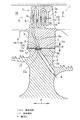
本発明のタービンのシール構造は、例えばガスタービンエンジンのタービンに適用されるものである。ガスタービンエンジンは、空気を圧縮する圧縮機、圧縮機からの圧縮空気に燃料を供給して燃焼させる燃焼器、および燃焼器からの高温、高圧の燃焼ガスにより駆動されるタービンを備えている。図1は、本発明の第1実施形態に係るタービン1を示す。タービン1の円板状のタービンディスク2の外周部に、タービン動翼である複数のタービン翼3が周方向に一定間隔をおいた配置で取り付けられている。タービン翼3は、燃焼ガスGの燃焼ガス通路18に位置する翼部8と、その径方向R内側に連続する翼取付部9とを有し、翼部8が燃焼ガスGのエネルギによって回転動力を受け、タービンディスク2を回転させる。
Hereinafter, preferred embodiments of the present invention will be described in detail with reference to the drawings.
The turbine seal structure of the present invention is applied to a turbine of a gas turbine engine, for example. The gas turbine engine includes a compressor that compresses air, a combustor that supplies and burns fuel to compressed air from the compressor, and a turbine that is driven by high-temperature, high-pressure combustion gas from the combustor. FIG. 1 shows a turbine 1 according to a first embodiment of the present invention. A plurality of
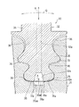
図2に示すように、タービンディスク2の外周部に、周方向Qに一定間隔をおいて複数の取付溝4が形成されており、この各取付溝4に、複数のタービン翼3の翼取付部9をそれぞれ嵌合させることにより、タービンディスク2に複数のタービン翼3が取り付けられている。翼取付部9の嵌合方向はタービン1の径方向Rと直交する方向であり、軸方向P(図1)に対して若干傾斜する場合もある。
As shown in FIG. 2, a plurality of mounting
タービンディスク2の取付溝4は、その両側溝面が周方向Qへの凹凸を有する曲線状の断面形状に、かつ両側溝面と溝底面4aとの境界部分が弧状の断面形状にそれぞれ形成されている。タービン翼3の翼取付部9は、取付溝4の断面形状にほぼ対応した外形を有し、かつ取付溝4に嵌合されたときに取付溝4に対し周方向Qおよび径方向Rの隙間10が複数生じる断面形状に形成されている。タービン翼2は、翼部8が燃焼ガスGにより加熱されるので、翼取付部9も高温化されて熱膨張する。前記隙間10は、翼取付部9の熱膨張を許容するために設けられている。
The mounting
図1に示すように、タービンディスク2には、圧縮機からの圧縮空気を、冷却媒体の一種である冷却空気Aとして外方から導入するための冷却通路2aが設けられ、タービン翼3には、タービンディスク2の冷却通路2aから冷却空気Aが供給される冷却通路3aが設けられている。タービンディスク2の冷却通路2aはタービンディスク2の背面から取付溝4の溝底面4aに向け延びている。図2に示すように、取付溝4の溝底面4aには、冷却通路2aに連通して溝底面4a上に開口する円形状の嵌合孔11が形成されており、この嵌合孔11は、通路断面が円形の冷却通路2aの内径D1よりも大きな内径D2を有している。
As shown in FIG. 1, the
前記嵌合孔11には貫通孔12aを有する薄い円柱状のシール材12が緊密に嵌合されている。「緊密に嵌合」とは、隙間のない状態で嵌合することを言い、したがって、シール材12の外周面と嵌合孔11の内周面との間が気密になっている。シール材12に同芯に形成された貫通孔12aは、タービンディスク2およびタービン翼3の各々の冷却通路2a,3aを互いに連通させて冷却通路の一部を形成するものであり、この貫通孔12aの内径D3は、タービンディスク2内の冷却通路2aの出口部2aaの内径D1およびタービン翼3内の冷却通路3aの入口部3aaの内径D4よりも小さく設定されている。
A thin
前記シール材12は、タービンディスク2の取付溝4の溝底面4aとタービン翼3の翼取付部9の先端面9aとの間に介装されるシム材13における幅方向(図2の左右方向)の中央部に固着されている。シール材12とシム材13は金属製である。シム材13は、タービンディスク2の取付溝4の溝底面4aとタービン翼3の翼取付部9の先端面9aとの間の隙間10よりも小さな厚みと、図5に示した従来のシール構造のシム材38よりも短い幅とを有している。また、シム材13の幅方向の中央部には、シール材12の貫通孔12aの内径D2およびタービン翼3の冷却通路3aの入口部3aaの内径D4よりもそれぞれ大きい内径を有する貫通孔13aが形成されている。
The sealing
シール材12が取り付けられたシム材13の底面部を示す図3において、シム材13の所定箇所にシール材12を重ね合わせた状態で、シム材13側から4点をスポット溶接Wすることで、シール材12がシム材13に取り付けられている。このようにスポット溶接Wすることにより、シム材13およびシール材12に対し熱による悪影響が生じることなしに、シール材12がシム材13に対し気密状態に強固に固定される。製造方法としては、シール素材の所定位置にシール材12を取り付けておき、このシール素材を所定形状に打ち抜き加工することにより、帯状の長手方向の一端部(図の左端部)に係合凹所13bを有する所定形状のシム材13が得られる。シム材13はタービン翼3のタービンディスク2への嵌合方向に平行で、軸方向Pに対して若干傾斜した方向に延びている。
In FIG. 3 which shows the bottom face part of the
他方、タービン翼3の翼取付部9には、図1に示す径方向Rの内方端における軸方向Pの一端部(図の左端部)に、軸方向Pおよび径方向内側に突出する係合突起14が形成されている。
On the other hand, the
タービン翼3は、以下の手順でタービンディスク2に取り付けられる。すなわち、シム材13と一体のシール材12をタービンディスク2の嵌合孔11に嵌合し、かつシム材13を取付溝4の溝底面4a上に載置した状態で、タービン翼3の翼取付部9を軸方向Pにおける図1の右方に向け移動させながら取付溝4に嵌合することにより、タービン翼3がタービンディスク2に取り付けられる。この取り付けが完了した時点で、翼取付部9の係合突起14がシム材13の係合凹所13bに嵌まり込んで係合し、シム材13のタービン翼3に対する軸方向Pの位置決めが行われる。
The
タービンディスク2の外方からタービンディスク2の冷却通路2aに導入された冷却空気Aは、図1のシール材12の貫通孔12aおよびシム材13の貫通孔13aを通ってタービン翼3の冷却通路3aに供給されたのち、翼部8内において径方向Rに複数回折り返す形状に形成された冷却通路3a内を流れて、下流の媒体室19の後縁開口20から燃焼ガス通路18へ排出される。これにより、翼部8が冷却空気Aによって効果的に冷却される。
The cooling air A introduced from the outside of the
この実施形態のタービン1のシール構造では、図2に示したように、円柱状のシール材12が、タービンディスク2の嵌合孔11に緊密に嵌合され、シール材12の貫通孔12aを介してタービンディスク2の冷却通路2aとタービン翼3の冷却通路3aとが連通している。
In the seal structure of the turbine 1 of this embodiment, as shown in FIG. 2, the
このように、円柱状のシール材12がタービンディスク2の嵌合孔11に緊密に嵌合されてシール材12の外周面と嵌合孔11の内周面との間が気密になっているから、シール材12とタービンディスク2との間のシールが確保される。一方、タービン回転時の遠心力と、タービンディスク2の冷却通路2aからの冷却空気Aの空気圧、つまりシール材12前後の冷却空気Aの圧力差とにより、シール材12が取り付けられたシム材13がタービン翼3の翼取付部9の先端面9aに押しつけられて接触するから、このシム材13とタービン翼3の翼取付部9との間のシールも確保される。これにより、タービンディスク2の冷却通路2aからシール材12の貫通孔12aを通ってタービン翼3の冷却通路3aに流入する冷却空気Aが、シール材12の周囲からタービン翼3の翼取付部9とタービンディスク2の取付溝4との間の隙間10へ漏れるのを抑制できる。その結果、タービン翼3の冷却効果が向上し、タービン翼3の長寿命化を図ることができる。この冷却効果を、既存のシム材に対して、シール材12を取り付け、かつタービンディスク2に嵌合孔11を形成するだけの簡単で安価な構成により得ることができる。
Thus, the
また、シム材で隙間を埋める従来のシール構造とは異なり、タービンディスク2の冷却通路2aの隙間10に対するシールは、嵌合孔11の内周面とシール材12の外周面とを気密にすることで確保できる。したがって、シム材13自身によってシールする必要がないから、シム材13の厚みを前記隙間10よりも十分に小さくできるので、シム材13の厚みが設計寸法よりも多少大きくなっても、前記隙間10よりも大きくなってシム材13が隙間10に挿入できなくなるおそれがない。したがって、シム材13は、厚みの精密な寸法管理が不要となるのに伴って高精度な加工を必要とせず、安価に製造できる。しかも、前記隙間10よりも十分薄いシム材13は当該隙間10内に容易に挿入できるので、組立性が向上する。
Further, unlike the conventional seal structure in which the gap is filled with the shim material, the seal against the
また、シール材12およびタービンディスク2の嵌合孔11は、円形状とすることにより、共に機械加工によって高い寸法精度で形成できるから、互いに正確な嵌め合い状態で緊密に嵌合することができる。さらに、シム材13は、タービンディスク2の嵌合孔11に緊密に嵌合されたシール材12に取り付けられて位置ずれが生じることがないので、タービン翼3の冷却通路3aの入口部3aaに対し常に正確に対向する。
In addition, since the sealing
さらに、冷却空気Aの漏れを防ぐ目的で隙間10を詰めるようにシム材13の厚みおよび幅を大きく設定する必要がないから、シム材13を、前記隙間10よりも薄い厚みで、かつ従来よりも狭い幅を有する形状にできる。したがって、タービン1の組み立てに際しては、シール材12を嵌合孔11に嵌合し、かつシム材13をタービンディスク2の取付溝4内に挿入したのち、タービン翼3の翼取付部9をタービンディスク2の取付溝4に嵌合する手順でタービン翼3をタービンディスク2に取り付けることが可能となる。このタービン翼3の取り付けの際に、翼取付部9が隙間10よりも薄いシム材13に強く接触してシム材13を変形させることがないとともに、幅の狭いシム材13が取付溝4と翼取付部9との間に噛み込むこともない。したがって、このシール構造では、図5の従来シール構造のようにタービンディスク50にタービン翼51を取り付けて形成される隙間52に、この隙間52と同じ厚みを有するシム材53を叩打しながら強制的に圧入する場合に比べて、組立性が向上する。
Furthermore, since it is not necessary to set the thickness and width of the
さらに、シム材13は、タービンディスク2の嵌合孔11に嵌合されたシール材12と、シム材13の係合凹所13bに翼取付部9の係合突起14に係合した係合凹所13bとにより、2点で位置決めされる。これにより、シム材13は、軸方向への位置ずれだけでなく軸方向に沿った水平面内における回り止めもなされるので、シム材13の正確な位置決めがなされる。シール材12の貫通孔12aの内径D3は、タービン翼3内の冷却通路3aの入口部3aaの内径D4よりも小さく設定されているので、タービン翼3の冷却通路3aへの冷却空気Aの供給量を貫通孔12aの内径を変えることで任意に調整することができる。
Furthermore, the
図4は本発明の第2実施形態に係るシール構造を示す横断面図であり、同図において、第1実施形態と同一若しくは相当するものに同一の符号を付して、重複する説明を省略する。このシール構造が第1実施形態のものと相違するのは、第1実施形態のシム材13を割愛して、タービン翼3の翼取付部9の先端面9aに、タービン1の回転時の遠心力によってシール材13が嵌まり込む凹部21が形成されている構成のみである。凹部21は、シール材12の外径D2(嵌合孔11の内径D2にほぼ同じ)よりも大きな内径D5を有し、底面21aが、機械加工により、シール材12の一端面12b(図4の上端面)に対し平行な平坦面に加工されて、シール材12の一端面12bが気密に接触できるようになっている。
FIG. 4 is a cross-sectional view showing a seal structure according to a second embodiment of the present invention, in which the same or corresponding parts as those in the first embodiment are denoted by the same reference numerals, and redundant description is omitted. To do. This seal structure is different from that of the first embodiment in that the
このシール構造は、タービン翼3の冷却通路3aの入口部3aaの内径D4がシール材12の外径D2よりも十分に小さいタービン1に対し好適に適用できるものである。シール材12が、タービン1の回転による遠心力と、シール材12前後の冷却空気Aの圧力差とにより、一端面12bが凹部21の底面21aに押しつけられて気密に接触する。このように、シール材12の外周面と嵌合孔11の内周面との間が気密になるようにシール材12が嵌合孔11に緊密に嵌合されることと、シール材12の一端面12bが凹部21の底面21aに気密に接触することとにより、タービンディスク2の冷却通路2aからシール材12の貫通孔12aを通ってタービン翼3の冷却通路3aに流入する冷却空気Aが、シール材12の周囲から4ービン翼3の翼取付部9とタービンディスク2の取付溝4との間の隙間10へ漏れるのを抑制できる。したがって、このシール構造においても、第1実施形態で説明したと同様の効果が得られるのに加えて、第1実施形態に比べて、シム材13が割愛される分だけ、構成を簡略化できる。
This seal structure can be suitably applied to the turbine 1 in which the inner diameter D4 of the inlet portion 3aa of the
本発明は、以上の実施形態で示した内容に限定されるものでなく、本発明の要旨を逸脱しない範囲内で、種々の追加、変更または削除が可能であり、そのようなものも本発明の範囲内に含まれる。例えば、前記シール材12は円柱状以外の柱状の形状でもよく、要するに、その外周面と嵌合孔11の内周面とが気密となるようにシール材12が嵌合孔11に緊密に嵌合されていればよい。
The present invention is not limited to the contents shown in the above embodiments, and various additions, modifications, or deletions can be made without departing from the spirit of the present invention. It is included in the range. For example, the sealing
1 タービン
2 タービンディスク
2a タービンディスクの冷却通路
3 タービン翼
3a タービン翼の冷却通路
4 取付溝
9 翼取付部
11 嵌合孔
12 シール材
12a 貫通孔
13 シム材
13b 係合凹所
14 係合突起
21 凹部
21a 凹部の底面
A 冷却空気(冷却媒体)
P 軸方向
Q 周方向
R 径方向
DESCRIPTION OF SYMBOLS 1
P axis direction Q circumferential direction R radial direction
Claims (5)
前記各タービン翼の翼取付部が前記タービンディスクにおける取付溝に径方向と直交する方向への嵌合により取り付けられ、
前記タービンディスクおよびタービン翼に、冷却媒体を前記タービンディスクの外方から内方を経て前記タービン翼内に導入する冷却通路が形成されており、
前記タービン翼の前記翼取付部と前記タービンディスクの取付溝との間の隙間にシム材が挿入され、
前記シム材に前記冷却通路の一部を形成する貫通孔を有するシール材が取り付けられ、前記タービンディスクに前記シール材が嵌合される嵌合孔が設けられ、
前記シール材の外周面と前記嵌合孔の内周面との間が気密となるように前記シール材が前記嵌合孔に緊密に嵌合され、
前記シム材が帯状であり、遠心力により前記タービン翼の前記翼取付部に押し付けられて接触して前記翼取付部との間をシールするタービンのシール構造。 A seal structure for a turbine that suppresses leakage of a cooling medium between a turbine disk and a plurality of turbine blades attached to the outer periphery of the turbine disk,
The blade attachment portion of each turbine blade is attached to the attachment groove in the turbine disk by fitting in a direction perpendicular to the radial direction,
A cooling passage is formed in the turbine disk and the turbine blade to introduce a cooling medium into the turbine blade from the outside to the inside of the turbine disk.
Shim material is inserted into the gap between the blade mounting portion of the turbine blade and the mounting groove of the turbine disk,
A sealing material having a through hole that forms a part of the cooling passage is attached to the shim material, and a fitting hole is provided in which the sealing material is fitted to the turbine disk.
The sealing material is tightly fitted into the fitting hole so that the outer circumferential surface of the sealing material and the inner circumferential surface of the fitting hole are airtight,
A turbine seal structure in which the shim material is strip-shaped and pressed against and contacted with the blade attachment portion of the turbine blade by centrifugal force .
Priority Applications (1)
| Application Number | Priority Date | Filing Date | Title |
|---|---|---|---|
| JP2011238242A JP5114590B2 (en) | 2011-10-31 | 2011-10-31 | Turbine seal structure |
Applications Claiming Priority (1)
| Application Number | Priority Date | Filing Date | Title |
|---|---|---|---|
| JP2011238242A JP5114590B2 (en) | 2011-10-31 | 2011-10-31 | Turbine seal structure |
Related Parent Applications (1)
| Application Number | Title | Priority Date | Filing Date |
|---|---|---|---|
| JP2009236901A Division JP4880019B2 (en) | 2009-10-14 | 2009-10-14 | Turbine seal structure |
Publications (2)
| Publication Number | Publication Date |
|---|---|
| JP2012062895A JP2012062895A (en) | 2012-03-29 |
| JP5114590B2 true JP5114590B2 (en) | 2013-01-09 |
Family
ID=46058824
Family Applications (1)
| Application Number | Title | Priority Date | Filing Date |
|---|---|---|---|
| JP2011238242A Active JP5114590B2 (en) | 2011-10-31 | 2011-10-31 | Turbine seal structure |
Country Status (1)
| Country | Link |
|---|---|
| JP (1) | JP5114590B2 (en) |
Families Citing this family (1)
| Publication number | Priority date | Publication date | Assignee | Title |
|---|---|---|---|---|
| WO2019102556A1 (en) * | 2017-11-22 | 2019-05-31 | 東芝エネルギーシステムズ株式会社 | Turbine blade and turbine |
Family Cites Families (2)
| Publication number | Priority date | Publication date | Assignee | Title |
|---|---|---|---|---|
| JPH09310603A (en) * | 1996-05-21 | 1997-12-02 | Hitachi Ltd | Gas turbine |
| JP3952629B2 (en) * | 1999-03-24 | 2007-08-01 | 株式会社日立製作所 | gas turbine |
-
2011
- 2011-10-31 JP JP2011238242A patent/JP5114590B2/en active Active
Also Published As
| Publication number | Publication date |
|---|---|
| JP2012062895A (en) | 2012-03-29 |
Similar Documents
| Publication | Publication Date | Title |
|---|---|---|
| JP4880019B2 (en) | Turbine seal structure | |
| JP4124614B2 (en) | Turbine disk side plate | |
| US10612397B2 (en) | Insert assembly, airfoil, gas turbine, and airfoil manufacturing method | |
| CN102132011B (en) | Fixed vane assembly for turbine engine with reduced weight, and a turbine engine including at least one such fixed vane assembly | |
| US9982553B2 (en) | Seal assembly including a notched seal element for arranging between a stator and a rotor | |
| US10508557B2 (en) | Gas turbine | |
| JPH116446A (en) | Sealing device for gas turbine | |
| CA2662039A1 (en) | Turbine shroud gas path duct interface | |
| JP6072930B2 (en) | Belly seal with underwrap end | |
| JP2010065698A (en) | Shroud for turbo machine | |
| JP2017141821A (en) | Centrifugal compressor assembly for use in turbine engine and method of assembly thereof | |
| JP3762661B2 (en) | Turbine rotor | |
| US20100008781A1 (en) | Method and Apparatus for Creating Seal Slots for Turbine Components | |
| US11434785B2 (en) | Jacket ring assembly for a turbomachine | |
| JP5705753B2 (en) | Seal structure of rotating machine and gas turbine provided with the same | |
| JP5114590B2 (en) | Turbine seal structure | |
| KR101660679B1 (en) | Gas turbine high-temperature component, gas turbine with same and method for producing gas turbine high-temperature component | |
| JP2013130136A (en) | Fastening part structure of turbocharger | |
| FR3048998A1 (en) | TURBINE ROTOR COMPRISING A VENTILATION SPACER | |
| JP2021195920A (en) | Turbine stationary blade | |
| EP4151834A1 (en) | Turbine stage sealing mechanism compensating thermal deformation | |
| JP2006220047A (en) | Sealing device for gas turbine | |
| US11408298B2 (en) | Sealing of a turbine | |
| US20220154591A1 (en) | Assembly for a turbomachine turbine | |
| JP7079343B2 (en) | Sealed structure between turbine shrouds |
Legal Events
| Date | Code | Title | Description |
|---|---|---|---|
| A521 | Request for written amendment filed |
Free format text: JAPANESE INTERMEDIATE CODE: A523 Effective date: 20120117 |
|
| A621 | Written request for application examination |
Free format text: JAPANESE INTERMEDIATE CODE: A621 Effective date: 20120117 |
|
| A977 | Report on retrieval |
Free format text: JAPANESE INTERMEDIATE CODE: A971007 Effective date: 20120927 |
|
| TRDD | Decision of grant or rejection written | ||
| A01 | Written decision to grant a patent or to grant a registration (utility model) |
Free format text: JAPANESE INTERMEDIATE CODE: A01 Effective date: 20121002 |
|
| A01 | Written decision to grant a patent or to grant a registration (utility model) |
Free format text: JAPANESE INTERMEDIATE CODE: A01 |
|
| A61 | First payment of annual fees (during grant procedure) |
Free format text: JAPANESE INTERMEDIATE CODE: A61 Effective date: 20121015 |
|
| FPAY | Renewal fee payment (event date is renewal date of database) |
Free format text: PAYMENT UNTIL: 20151019 Year of fee payment: 3 |
|
| R150 | Certificate of patent or registration of utility model |
Ref document number: 5114590 Country of ref document: JP Free format text: JAPANESE INTERMEDIATE CODE: R150 Free format text: JAPANESE INTERMEDIATE CODE: R150 |
|
| R250 | Receipt of annual fees |
Free format text: JAPANESE INTERMEDIATE CODE: R250 |