JP5113850B2 - Termination cassette release latch - Google Patents
Termination cassette release latch Download PDFInfo
- Publication number
- JP5113850B2 JP5113850B2 JP2009532573A JP2009532573A JP5113850B2 JP 5113850 B2 JP5113850 B2 JP 5113850B2 JP 2009532573 A JP2009532573 A JP 2009532573A JP 2009532573 A JP2009532573 A JP 2009532573A JP 5113850 B2 JP5113850 B2 JP 5113850B2
- Authority
- JP
- Japan
- Prior art keywords
- cassette
- terminated
- patch panel
- tab
- latch
- Prior art date
- Legal status (The legal status is an assumption and is not a legal conclusion. Google has not performed a legal analysis and makes no representation as to the accuracy of the status listed.)
- Active
Links
Images


Classifications
-
- H—ELECTRICITY
- H04—ELECTRIC COMMUNICATION TECHNIQUE
- H04Q—SELECTING
- H04Q1/00—Details of selecting apparatus or arrangements
- H04Q1/02—Constructional details
- H04Q1/13—Patch panels for monitoring, interconnecting or testing circuits, e.g. patch bay, patch field or jack field; Patching modules
-
- H—ELECTRICITY
- H04—ELECTRIC COMMUNICATION TECHNIQUE
- H04Q—SELECTING
- H04Q1/00—Details of selecting apparatus or arrangements
- H04Q1/18—Electrical details
- H04Q1/20—Testing circuits or apparatus; Circuits or apparatus for detecting, indicating, or signalling faults or troubles
-
- H—ELECTRICITY
- H04—ELECTRIC COMMUNICATION TECHNIQUE
- H04Q—SELECTING
- H04Q1/00—Details of selecting apparatus or arrangements
- H04Q1/02—Constructional details
- H04Q1/14—Distribution frames
Description
本発明は、成端済カセットに関し、より具体的にはパッチパネル内に取り付けられている成端済カセットを取り外すための解放ラッチに関する。 The present invention relates to a terminated cassette, and more particularly to a release latch for removing a terminated cassette mounted in a patch panel.
本特許出願は、35U.S.C.第119条(e)に基づき、2006年10月11日に出願された米国仮特許出願第60/829,070号に対する優先権を主張し、同仮出願の開示全体を参考文献としてここに援用する。本特許出願は、更に、35U.S.C.第119条(e)に基づき、2007年8月9日に出願された米国仮特許出願第60/954,863号に対する優先権を主張し、同仮出願の開示全体を参考文献としてここに援用する。 This patent application is filed in 35U. S. C. Claims priority to US Provisional Patent Application No. 60 / 829,070, filed October 11, 2006, based on Section 119 (e), the entire disclosure of that provisional application is incorporated herein by reference. To do. This patent application is further described in 35U. S. C. Claims priority to US Provisional Patent Application No. 60 / 954,863, filed on August 9, 2007, under section 119 (e), the entire disclosure of which is incorporated herein by reference. To do.
成端済の銅又はファイバーケーブルカセットを使えば、ケーブルをパッチパネルへ迅速且つ確実に取り付けることができるようになる。成端済カセットは、出荷前に、顧客の仕様に基づいて組み立てられる。カセットの性能も、顧客に出荷する前に検証される。従って、新しいデータセンターを取り付けるか又は既存のデータセンターを変更しようとする顧客は、一般に現場でのケーブル端子処理、テスト実施、及び取り付けに伴うデータセンターの停止時間を最小限に抑えるのに役立つ成端済カセットを使用することができる。 Using a terminated copper or fiber cable cassette allows the cable to be quickly and reliably attached to the patch panel. The terminated cassette is assembled based on customer specifications before shipment. Cassette performance is also verified before shipping to customers. Therefore, customers who are installing a new data center or modifying an existing data center will generally be able to help minimize data center downtime associated with on-site cable termination, test execution, and installation. A finished cassette can be used.
先行技術による成端済カセットは、カセットの上面に位置するラッチ又はスライドアームを含んでいる。これらのカセットは、一旦パッチパネルに取り付けられてしまうと、ラッチに容易にアクセスすることができないため、カセットを取り外すことがしばしば難しくなる。複数のカセットがデータセンターのパッチパネルに取り付けられている場合は、ラッチを外し成端済カセットを取り外すことは、顧客がケーブルの列の間に手を入れてラッチを外す必要があるため、難しくなる。而して、容易にアクセスすることができ、パッチパネルから取り外し易くする解放機構を有する、成端済カセットが必要とされている。 Prior art terminated cassettes include a latch or slide arm located on the top surface of the cassette. Once these cassettes are attached to the patch panel, it is often difficult to remove the cassettes because the latches are not easily accessible. If multiple cassettes are attached to the data center patch panel, it is difficult to unlatch and remove the terminated cassettes because the customer has to put a hand between the cable rows to unlatch. Become. Thus, there is a need for a terminated cassette that has a release mechanism that is easily accessible and easy to remove from the patch panel.
パッチパネルの中へ取り付けられる成端済カセット用の解放ラッチを説明する。成端済カセットは、カセットを保持するための保持機構を含んでいるパッチパネルから、カセットを取り外せるようにするための解放ラッチを含んでいる。解放ラッチは、成端済カセットの側壁に位置する片持ち梁を含んでいる。片持ち梁は、梁を側壁に対して撓ませることのできるヒンジ点を有している。解放ラッチは、更に、片持ち梁の遠位端に設けられている押圧タブと、片持ち梁の表面から突き出ているラッチタブを含んでいる。ラッチタブは、ヒンジ点と押圧タブの間に位置している。ラッチタブは、カセットをパッチパネルに取り付ける時、パッチパネルの保持機構と係合させることができる。 A release latch for a terminated cassette mounted in a patch panel is described. The terminated cassette includes a release latch that allows the cassette to be removed from a patch panel that includes a holding mechanism for holding the cassette. The release latch includes a cantilever located on the side wall of the terminated cassette. The cantilever beam has a hinge point that can deflect the beam relative to the side wall. The release latch further includes a push tab provided at the distal end of the cantilever and a latch tab protruding from the surface of the cantilever. The latch tab is located between the hinge point and the pressing tab. The latch tab can be engaged with a retention mechanism of the patch panel when the cassette is attached to the patch panel.
成端済カセットの各側壁は、解放ラッチを有しているのが望ましい。更に、ラッチタブと、パッチパネルの保持機構は、互いに相補的な形状を有している。ラッチタブと保持機構が互いに係合することができる限り、様々な相補的形状を使用することができる。 Each side wall of the terminated cassette preferably has a release latch. Further, the latch tab and the patch panel holding mechanism have complementary shapes. Various complementary shapes can be used as long as the latch tab and the retention mechanism can engage each other.
ラッチタブは、押圧タブをカセットの側壁に対し内向きに押すと、好適に内向きに撓ませることができる。ラッチタブは、内向きに撓ませると、パッチパネルの保持機構から外すことができる。 The latch tab can be flexed inward preferably when the pressing tab is pressed inward against the side wall of the cassette. The latch tab can be removed from the patch panel retention mechanism when deflected inward.
或る好適な実施形態では、成端済カセットは、同カセットの側壁から伸張していて、押圧タブに隣接して位置する把持面を含んでいる。例えば、把持面は、成端済カセットの後部に位置する壁伸張部であってもよい。把持面は、カセットをパッチパネルに挿入する際又はパッチパネルから取り外す際に掴む追加の表面を利用者に提供することができる。 In certain preferred embodiments, the terminated cassette includes a gripping surface extending from the side wall of the cassette and positioned adjacent to the pressing tab. For example, the gripping surface may be a wall extension located at the rear of the terminated cassette. The gripping surface can provide the user with an additional surface to grip when inserting or removing the cassette from the patch panel.
解放ラッチを有する成端済カセットを受け入れるためのパッチパネルについても説明する。パッチパネルは、上及び下フランジを有するフレームを含んでいる。パネルは、上フランジから下向きに伸張している複数の上パネルタブと、下フランジから上向きに伸張している複数の下パネルタブを含んでいる。パッチパネルは、更に、上パネルタブを受け入れることができるようになっている上スロットと下パネルタブを受け入れることができるようになっている下スロットとを有する、複数の側面ガイドを含んでいる。側面ガイドは、一対のガイドラッチタブを含んでいる。両ガイドラッチタブは、側面ガイドの後端から外向きに伸張していて、反対方向を向いている。ガイドラッチタブは、パッチパネルのための保持機構を含んでいてもよい。好適なことに、パッチパネルは、解放ラッチを有する成端済カセットが隣接する側面ガイドの間に受け入れられた時、同カセットを保持するようになっている。 A patch panel for receiving a terminated cassette having a release latch is also described. The patch panel includes a frame having upper and lower flanges. The panel includes a plurality of upper panel tabs extending downward from the upper flange and a plurality of lower panel tabs extending upward from the lower flange. The patch panel further includes a plurality of side guides having an upper slot adapted to receive an upper panel tab and a lower slot adapted to receive a lower panel tab. The side guide includes a pair of guide latch tabs. Both guide latch tabs extend outward from the rear end of the side guide and face in opposite directions. The guide latch tab may include a retention mechanism for the patch panel. Preferably, the patch panel is adapted to hold the cassette when a terminated cassette having a release latch is received between adjacent side guides.
別の実施形態では、成端済カセットを保持するための保持機構を含んでいるパッチパネルの中へ取り付ける成端済カセットは、解放タブを備えている。解放タブは、成端済カセットの表面に接続されている固定端と、カセットの側壁に沿って伸張している自由端を有している。解放タブは、更に、タブの固定端と自由端の間に位置するヒンジ部分を含んでいる。タブがカセットの側壁に向けて内向きに押圧されると、自由端は、カセットをパッチパネルから取り外せるように、パッチパネルの保持機構と相互に作用し合う。好適なことに、解放タブがカセットの側壁と保持機構の間に差し込まれていて、保持機構をカセットの側壁から離れる方向に撓ませるようになっている。 In another embodiment, a terminated cassette that is mounted into a patch panel that includes a retention mechanism for retaining the terminated cassette includes a release tab. The release tab has a fixed end connected to the surface of the terminated cassette and a free end extending along the side wall of the cassette. The release tab further includes a hinge portion located between the fixed end and the free end of the tab. When the tab is pressed inward toward the side wall of the cassette, the free end interacts with the patch panel retention mechanism so that the cassette can be removed from the patch panel. Preferably, a release tab is inserted between the side wall of the cassette and the holding mechanism so as to deflect the holding mechanism away from the side wall of the cassette.
上記及び他の態様並びに利点は、適宜、添付図面を参照しながら、以下の詳細な説明を読んで頂ければ当業者には明らかになるであろう。更に、この概要は、一例に過ぎず、特許請求の範囲に記載の本発明の範囲を限定する意図はないものと理解頂きたい。 These and other aspects and advantages will become apparent to those of ordinary skill in the art by reading the following detailed description, with reference where appropriate to the accompanying drawings. Further, it is to be understood that this summary is merely an example and is not intended to limit the scope of the invention as recited in the claims.
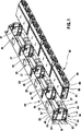
図1と図2は、複数の側面ガイド50がパッチパネル内に取り付けられている代表的なパッチパネル20を示している。パッチパネル20は、隣接する側面ガイド50の間に配置される多数の成端済カセット80を受け入れる。成端済カセット80は、カセット80が隣接する側面ガイド50の間をパッチパネル20にパチンと嵌るまで、パッチパネル20の中へ真っ直ぐに挿入される。
1 and 2 show a
図3は、本発明の側面ガイド50を備えたパッチパネル20の分解図を示している。パッチパネル20は、上フランジ24と下フランジ26と複数の開口部28とを有するフレーム22を含んでいる。パッチパネル20の各端部は、パッチパネルをネットワークラック(図示せず)に固定するための取付穴34を有する取付板32を含んでいる。
FIG. 3 shows an exploded view of the
パッチパネル20は、複数のパネルタブ40、41を含んでいる。図3に示しているように、パネルタブ40は、上フランジ24から下向きに伸張し、パネルタブ41は、下フランジ26から上向きに伸張している。パネルタブ40は、パネルタブ41より短くてもよい。パネルタブ40、41は、パッチパネル20の各開口部28の端近くに位置している。パッチパネル20の上フランジ24は、更に、複数の方向合わせ用ノッチ42を含んでいる。方向合わせ用ノッチ42は、パッチパネルフレーム22の上フランジ24から伸張しているパネルタブ40の後方に配置されている。
The
パッチパネルの上フランジ24と下フランジ26は、更に、複数の支持フランジ25、27それぞれを含んでいる。支持フランジ25と27は、カセットがパッチパネル内に取り付けられる時、各成端済カセットを心合わせして、各成端済カセットを案内する働きをする。
The
図3は、更に、本発明の側面ガイド50の1つがパッチパネル20に取り付けられる前の状態を示しており、図4と図5は、側面ガイド50がパッチパネル20に取り付けられた状態を示している。側面ガイド50は、成端済カセットをパッチパネル20内に保持するために、保持機構を含んでいてもよい。支持フランジ25と27に加え、側面ガイド50も、成端済カセット80がパッチパネル20内に正しく位置決めされるように、同カセット80を案内する。側面ガイド50は、更に、カセット80が確実にパッチパネル20に固定されるようにしている。
FIG. 3 further shows a state before one of the side guides 50 of the present invention is attached to the
各側面ガイド50の上面52と下面54は、それぞれ開口部又はスロット56、57を含んでいる。下で論じるが、側面ガイド50がパッチパネル20に取り付けられる時、スロット56は、パネルタブ40の内の1つを受け入れ、スロット57は、パネルタブ41の内の1つを受け入れる。側面ガイド50は、更に、側面ガイド50内の、側面ガイド50の上面52と下面54の付近に配置されているガイドタブ60を含んでいる。ガイドタブ60は、側面ガイド50がパッチパネル20に取り付けられる時、パネルタブ40、41と係合するように設計されている。
The upper and
側面ガイド50の上面52は、更に、方向合わせ用タブ62を含んでいる。方向合わせ用タブ62は、パッチパネル20の方向合わせ用ノッチ42と整列して、側面ガイド50が確実にパッチパネル20に正しく取り付けられるようにする。各側面ガイド50の中心部は、側面ガイド50の背面から外向きに伸張する一対の可撓性を有するガイドラッチタブ64を含んでいる。ガイドラッチタブ64は、成端済カセット80がパッチパネル20に取り付けられる時に、カセットの側壁82に係合するリップ66を含んでいる(図2及び図6から図9参照)。代わりのやり方では、ガイドラッチタブ64は、パッチパネル20に取り付けられる時に、成端済カセット115のラッチタブ128(図12から図17参照)、又は成端済高密度マルチファイバープッシュオン(MPO)型ケーブルアッセンブリ150のラッチタブ128(図18及び図19参照)と係合するリップを含んでいる。
The
側面ガイド50は、パネルタブ40、41がスロット56、57の中にそれぞれ入るように、滑らせてパッチパネル20に差し込まれる。パネルタブ40とパネルタブ41は、確実に、側面ガイド50がパッチパネルに正しく取り付けられるようにするために、スロット56とスロット57それぞれとしか嵌り合わないキーを形成している。側面ガイド50を滑らせてパッチパネル20に差し込むと、ガイドタブ60はパネルタブ40、41と係合する。更に、方向合わせ用タブ62が方向合わせ用ノッチ42と整列した状態に維持されることによって、確実に、側面ガイド50がパッチパネル20に正しく取り付けられる。図4に示しているように、側面ガイド50は、側面ガイド50がパッチパネルフレーム22と面一になり、方向合わせ用タブ62がパッチパネル20の方向合わせ用ノッチ42内に位置決めされるように、パッチパネル20に取り付けられる。
The side guide 50 is slid into the
図1、図2及び図6から図9に示しているように、本発明の或る実施形態による成端済カセット80は、一対の解放タブ84を含んでいる。解放タブ84は、カセット80の後方角部から伸張し、成端済カセット80の側壁82に沿って配置されている。解放タブ84は、自由端88を有するヒンジ部分86を含んでいる。自由端88は、カセットの側壁82に向けて下向きに伸張している。解放タブ84は、本発明の譲受人に譲渡されている米国特許第5,993,236号に開示されているモジュラープラグのラッチアームと同様であり、同特許を参考文献としてここに援用する。
As shown in FIGS. 1, 2, and 6-9, the terminated
図2、図6、及び図7は、パッチパネル20の側面ガイド50に取り付けられた成端済カセット80を示している。ガイドラッチタブ64のリップ66は、成端済カセット80をパッチパネル20内に維持するために、成端済カセットの側壁82と係合している。成端済カセット80の解放タブ84は、ガイドラッチタブ64の内の1つに隣接して位置している。
2, 6 and 7 show the terminated
図8及び図9に示しているように、パッチパネル20から成端済カセット80を取り外すには、解放タブ84を押圧して、ガイドラッチタブ64がカセットの側壁82から外れ始めるようにする。解放タブ84は、カセットの側壁82とガイドラッチタブ64の間に差し込まれて、ガイドラッチタブ64を変位させる。解放タブ84を一杯に押圧すると、ガイドラッチタブ64は、カセットの側壁82を障害とならないようにかわして、成端済カセット80がパッチパネル20から取り外せるようにする。
As shown in FIGS. 8 and 9, to remove the terminated
本発明のこの実施形態の成端済カセット80と解放機構は、或る角度に曲げられたパッチパネルと共に、又は高密度パッチパネルと共に使用することができる。一例として、図10は、成端済カセット80を受け入れるための本発明の側面ガイド50を備えた、或る角度に曲げられたパッチパネル120を示している。図11は、本発明の側面ガイド50が成端済カセット80を受け入れるために取り付けられている高密度パッチパネル220を示している。
The terminated
成端済カセット80の解放機構は、顧客が、所望の移動、追加、又は変更を行う場合に、工具を使用せずに片手だけを使って、成端済カセットをパッチパネルから素早く取り外すことができるようにしている。
The release mechanism of the terminated
図12から図17は、本発明の成端済カセットのもう1つの実施形態である、成端済カセット115を示している。本発明のこの追加の実施形態は、図6から図9に関連して説明した成端済カセット80と同様である。例えば、この追加の実施形態は、成端済カセット80を取り付けることができる、上で説明した同じパッチパネル20に取り付けることができる。図17に示しているように、パッチパネル20は、多数の成端済カセット115が側面ガイド50の間に配置されるように、成端済カセット115を受け入れる。成端済カセット115は、同カセット115が隣接する側面ガイド50の間をパッチパネル20にパチンと嵌るまで、パッチパネル20の中へ真っ直ぐに挿入される。但し、成端済カセット80とは異なり、図12から図17に示されている実施形態は、成端済カセット80の解放機構とは異なる解放機構を有している。以下に、成端済カセット115の解放機構を詳細に説明する。
FIGS. 12-17 show a
図12は、成端済カセット115の部分後面斜視図を示している。成端済カセット115は、カセット基部121とカセットカバー123を有している。カセット基部121は、解放ラッチ122を含んでいる。代わりに、カセットカバー123が解放ラッチを含んでいてもよい。図13と図14は、成端済カセット115のカセット基部121の斜視図であり、解放ラッチ122を更に詳細に示している。
FIG. 12 shows a partial rear perspective view of the terminated
成端済カセット115は、一対の解放ラッチ122を含んでいる。図12から図14は、成端済カセット又はカセット基部の一方の側の部分図を示しているが、反対側も実質的に同様の解放ラッチ設計を有しているものと理解頂きたい。解放ラッチ122は、成端済カセット基部121の側壁125に位置している。解放ラッチ122は、ヒンジ点126とラッチタブ128と押圧タブ130を有する片持ち梁24である。カセット基部121は、カセット基部121の縁部から伸張している壁伸張部134を好適に含んでいる。壁伸張部134は、カセット基部121の後部に、解放ラッチ122の上方に配置されている。
The terminated
成端済カセット基部の側壁125のスロット136は、片持ち梁124を形成する働きをする。図示のように、スロット136は、成端済カセット基部の底に向けて配置されている。スロットは、ヒンジ点126から壁伸張部134まで伸張していてもよい。
The
解放ラッチ122は、更に、ラッチタブ128を含んでいる。ラッチタブ128は、成端済カセット基部121の片持ち梁124から突き出ている部分である。解放ラッチは、更に、押圧タブ130を含んでいる。押圧タブ130を内向きに押し付けると、ラッチタブ128は、ラッチタブ128が片持ち梁のヒンジ点126と押圧タブ130の間に配置されているので、内向きに動く。更に、カセット基部121の側壁125は、壁伸張部134を含んでいる。この壁伸張部は、カセット基部121の後部に位置しており、押圧タブ130の上方に好適に位置している。壁伸張部は、把持面として好適に働き、好都合にも、顧客が成端済カセットを取り付けるか又は取り外すために押圧タブ130を押している時に、顧客に追加の把持部を提供している。
更に、或る好適な実施形態では、成端済カセット基部121は、図14に示しているように、カセット基部121の内部142のリブ140にノッチ138を含んでいる。ノッチ138は、解放ラッチ122のためのクリアランスを提供するために、内部リブ140に設けられている。更に、ノッチ138は、解放ラッチ122の片持ち梁124が過剰に撓むのを防ぐための、解放ラッチ122の積極的な停止装置としても働く。過剰な撓みは、片持ち梁のヒンジ点126に過度な応力を引き起こす可能性がある。ノッチ138は、ヒンジ点126の応力を好適に制限しており、これにより解放ラッチの構造的な安定性と強度が増す。
Further, in certain preferred embodiments, the terminated
成端済カセット115の様な成端済カセットは、上で説明したパッチパネルに容易に取り付け取り外すことができる。図15と図16は、パッチパネル20の側面ガイド50に取り付けられた成端済カセット115を示している。パッチパネル20のガイドラッチタブ64のリップ66は、解放ラッチ122のラッチタブ128と係合して、成端済カセット115をパッチパネル20内に維持している。互いに係合するために、ガイドラッチタブ64とラッチタブ128は相補的な形状を有している。図15と図16は、ガイドラッチタブとラッチタブの相補的な形状の1つの例を示しているが、ガイドラッチタブとラッチタブについては、ガイドラッチタブとラッチタブが係合する限り、他の形状も可能であるものと理解頂きたい。成端済カセット115がパッチパネル20の中に完全に挿入されると、ラッチタブ128は、ガイドラッチタブ64の後ろにパチンと嵌って係止する。ラッチタブ128がガイドラッチタブ64に係合すると、パッチパネル20は、成端済カセット115をしっかり係止して所定の位置に保持する。
A terminated cassette, such as terminated
更に、成端済カセットに機械的な荷重が掛けられる事態が生じた時、パッチパネル20と成端済カセット115のそれぞれのラッチは、成端済カセット115をパッチパネル内の所定の位置にしっかりと保持するよう働く。解放ラッチ122は、好適にも自己増力ラッチなので、カセットに後向き又は横の荷重が掛かると、ラッチは、パッチパネルの保持機構との係合を強める。例えば、成端済カセット115に後向き及び/又は横向きの荷重が掛けられるというシナリオでは、パッチパネル20のガイドラッチタブ64と成端済カセット115のラッチタブ128は係合を強める。より具体的には、成端済カセット115に後ろ又は横向きの荷重が掛かると、ガイドラッチタブ64とラッチタブ128は、荷重の無いシナリオよりも一層強く互いに係合することになる。例えば、成端済カセットのケーブルが誤って引かれたり、ぐっと強く引っ張られたり、又は捻られると、ガイドラッチタブ64とラッチタブ128は相互係合を強めるので、成端済カセット115はパッチパネル20にしっかりと装着された状態に留まる。
Further, when a mechanical load is applied to the terminated cassette, the respective latches of the
図16に示しているように、成端済カセット115をパッチパネル20から取り外すには、押圧タブ130を押圧して、ガイドラッチ64が成端済カセット115のラッチタブ128から外れ始めるようにする。成端済カセット115をパッチパネルから取り外す場合、顧客は、壁伸張部134と押圧タブ130を掴むことによって成端済カセット115を把持し、押圧タブを内向きに押せば、成端済カセット115をパッチパネル20から引き出すことができる。図16に点線で示されているように、押圧タブを内向きに押圧するか又は押すと、ラッチタブ128も内向きに撓む。押圧タブとラッチタブ128が内向きに動くことによって、ラッチタブはパッチパネル20のガイドラッチタブ64のリップ66から外れる。ラッチタブ128は、パッチパネル20のガイドラッチタブ64のリップ66を障害とならないようにかわす。ラッチタブ128がガイドラッチ64のリップ66をかわすと、成端済カセット115はパッチパネル20から容易に取り外せるようになる。
As shown in FIG. 16, to remove the terminated
成端済カセット80の場合と同じように、本発明のこの実施形態の成端済カセット115と解放ラッチも、角の付いたパッチパネルと共に又は高密度パッチパネルと共に使用することができる。一例として、図10は、成端済カセット80又は成端済カセット115の様な成端済カセットを受け入れることのできる本発明の側面ガイド50を備えている、或る角度に曲げられたパッチパネル120を示している。図11は、成端済カセットを受け入れるために本発明の側面ガイド50が取り付けられている高密度のパッチパネル220を示している。
As with the terminated
本発明のこの実施形態の利点は、成端済カセット115をパッチパネルから取り外そうとする際、ラッチを解放してカセットを自由にするのに、圧迫力をほとんど加える必要がないことである。片持ち梁は、圧力が加えられると容易に撓む。更に、上で説明したラッチ84を有する成端済カセット80の場合と同じように、成端済カセット115の解放ラッチ122は、顧客が、所望の移動、追加、又は変更を行う場合に、工具を使用せず片手だけを使って、成端済カセットをパッチパネルから素早く取り外すことができるようにしている。
An advantage of this embodiment of the present invention is that when attempting to remove the terminated
更に、成端済カセット115の壁伸張部の造形は、好都合にも、成端済カセットをパッチパネルから取り外す際に、顧客が握るのに都合のよい構造を提供している。把握部のおかげで、顧客は、パッチパネルからのカセットの取り外しを支援するために、成端済カセットのケーブルを握る必要がなくなる。例えば、成端済カセット115が光ファイバーの成端済カセットであるというシナリオでは、パッチパネルからのカセット取り外しを支援するのに、顧客に光ファイバーケーブルを握るよう要求するのは望ましくない。顧客が取り外しを支援するために光ファイバーケーブルを握れば、光ファイバーコネクタの端子又はファイバーに傷のつく恐れがある。既に説明した解放ラッチと壁伸張部とのおかげで、使用者は、取り外しを支援するためにケーブルを握る必要なしに、成端済カセットをパッチパネルから容易に取り外すことができる。
Furthermore, the shaping of the wall extension of the terminated
図18と図19には、本発明の別の実施形態を示している。具体的には、図18と図19は、本発明の或る実施形態による成端済の高密度マルチファイバープッシュオン(MPO)ケーブルアッセンブリ150を示している。図18と図19に示されているように、カセットアッセンブリ150は、成端済カセット115に関して先に説明したものと同じ解放ラッチ122を含んでいる。従って、カセットアッセンブリ150は、成端済カセット80と成端済カセット115の何れをも取り付けることのできる、上で説明した同じパッチパネル20に取り付けることができる。
18 and 19 show another embodiment of the present invention. Specifically, FIGS. 18 and 19 illustrate a terminated high density multi-fiber push-on (MPO)
図19は、成端済高密度MPOケーブルアッセンブリ150の分解図を示している。カセットアッセンブリ150は、基部152とカバー154を含んでいる。基部とカバーは一体にパチンと嵌め合わすことができる。カセットアッセンブリ150は、更に、基部152にパチンと嵌め込むことができるMPO様式のアダプター156を含んでいる。基部は、MPO様式のアダプター156を保持する矩形穴158を含んでいる。矩形穴158は、MPO様式のアダプター156を受け入れて係止する。6つの矩形穴158が示されているが、必要とされるMPO様式のアダプター156の数が少ない場合は、設ける穴158も少なくてよい。
FIG. 19 shows an exploded view of the terminated high density
マルチファイバーケーブル160は、MPO光ファイバーコネクタ162で成端されている。ファイバーコネクタ162とMPO様式のアダプター156は、基部152に取り付けられると、コネクタがアダプターに嵌り込む。ケーブル160は、歪み緩和金具164と保持用ナット166によって基部152に取り付けられている。ケーブル160の強度部材は、スクリュー168とナット170によって基部に好適に取り付けられている。基部の中には、スクリュー168用の穴となるボス172が設けられていてもよい。更に、強度を高めるために、ボス172にガセット174を付け加えてもよい。強度部材を基部に取り付けることによって、野外ケーブルを取り付ける際に要求される追加の引っ張り強度が好適に提供される。
The
カセットアッセンブリ150は、更に、カセットの後部に角度の付いた輪郭180を含んでいる。角度の付いた輪郭180は、カセットを装着相手のパッチパネルに挿入し及び取り外す場合のクリアランスを提供する働きをする。これは、様々な理由で好都合である。例えば、顧客は、カセットとカセットの間に手を入れて、他のカセットを乱すことなく個別のカセットを取り外すことができる。更に、角度の付いた輪郭180は、カセット150をパッチパネル20に挿入し又はパッチパネル20から取り外す際に、顧客が握る追加の把持部を提供する。角度の付いた輪郭180のおかげで、顧客は、パッチパネルから取り外すのを支援するためにケーブル160を握る必要がなくなる。更に、カセットアッセンブリ150は角度の付いた輪郭を有しているので、追加の把握部を提供する壁伸張部134は必ずしも必要ではない。しかしながら、カセットアッセンブリ150は、追加の把握部となる壁伸張部134を含んでいてもよいものと理解頂きたい。
The
上で論じたように、カセットアッセンブリ150は、パッチパネル20の様なパッチパネルに取り付けることができる。解放ラッチ122を有するカセットアッセンブリ150は、或る角度に曲げられたパッチパネルと共に又は高密度のパッチパネルと共に使用することができる。例えば、或る好適な実施形態では、カセットアッセンブリ150は、図10に示している或る角度に曲げられたパッチパネル120に取り付けることができる。カセットアッセンブリ150の角度の付いた輪郭180のおかげで、カセットは、既に取り付けられている隣接するカセットに邪魔されることなく、装着相手の或る角度に曲げられたパッチパネル120に挿入することができる。同様に、カセットは、パッチパネルに取り付けられている隣接するカセットに邪魔されることなく、装着相手の或る角度に曲げられたパッチパネル120から取り外すことができる。
As discussed above, the
以上、本発明の特定の好適な実施形態を示し説明してきたが、当業者には明らかなように、本発明には、本発明の教示から逸脱することなく、変更及び修正を加えることができる。これまでの説明に記載され添付図面中に示されている事柄は、説明のみを目的として提示したものであり、何ら限定を課すものではない。 While certain preferred embodiments of the invention have been shown and described, it will be apparent to those skilled in the art that changes and modifications can be made to the invention without departing from the teachings of the invention. . Matters described in the foregoing description and shown in the accompanying drawings are presented for illustrative purposes only and are not intended to be limiting.
図示の実施形態は一例に過ぎず、本発明の範囲を限定するものと見なすべきではないと解釈して頂きたい。特許請求の範囲に記載の内容は、その趣旨の記載がない限り、記載されている順序又は要素に限定されるものと読み取るべきではない。従って、特許請求の範囲に記載の内容及びその等価物の範囲及び精神に含まれる全ての実施形態は、本発明の特許請求の対象となる。 The illustrated embodiments are merely examples and should not be construed as limiting the scope of the invention. The content of the claims should not be read as limited to the described order or elements unless stated to that effect. Accordingly, all embodiments that come within the scope and spirit of the following claims and their equivalents are the subject of the claims of the present invention.
20 パッチパネル
22 フレーム
24 上フランジ
25、27 支持フランジ
26 下フランジ
28 開口部
32 取付板
34 取付穴
40、41 パネルタブ
42 方向合わせ用ノッチ
50 側面ガイド
52 上面
54 下面
56、57 スロット
60 ガイドタブ
62 方向合わせ用タブ
64 ガイドラッチタブ
66 リップ
80 成端済カセット
82 側壁
84 解放タブ
86 ヒンジ部
88 自由端
115 成端済カセット
120 或る角度に曲げられたパッチパネル
121 基部
122 解放ラッチ
123 カセットカバー
124 片持ち梁
125 側壁
126 ヒンジ点
128 ラッチタブ
130 押圧タブ
134 壁伸張部
136 スロット
138 ノッチ
140 リブ
142 基部内部
150 カセットアッセンブリ、ケーブルアッセンブリ
152 基部
154 カバー
156 アダプター
158 穴
160 ケーブル
162 コネクタ
164 歪み緩和金具
166 保持用ナット
168 スクリュー
170 ナット
172 ボス
174 ガセット
180 角度の付いた輪郭
220 高密度パッチパネル
20
Claims (18)
前記成端済カセットの側壁に位置する片持ち梁であって、前記梁を前記側壁に対し撓ませることができるヒンジ点を有している、片持ち梁と、
前記片持ち梁の遠位端に設けられている押圧タブと、
前記片持ち梁の表面の前記ヒンジ点と前記押圧タブの間から突き出ているラッチタブであって、前記カセットが前記パッチパネルに取り付けられる時、前記パッチパネルの前記保持機構と係合することができる、ラッチタブと、を備え、
前記成端済カセットの各側壁は、前記パッチパネルの保持機構と係合することができる解放ラッチを有し、
前記解放ラッチは、前記成端済カセットの前記側壁内のスロットによって形成されている、成端済カセット。A termination cassette mounted in a patch panel having a retention mechanism for retaining the terminated cassette, the termination cassette having a release latch that allows the cassette to be removed from the panel. In the finished cassette, the release latch is
A cantilever beam located on a side wall of the terminated cassette, the cantilever having a hinge point capable of deflecting the beam with respect to the side wall;
A pressing tab provided at the distal end of the cantilever;
A latching tab protruding from between the hinge point of the surface of the cantilever and the pressing tab, and can engage with the holding mechanism of the patch panel when the cassette is attached to the patch panel. includes a latching tab, the,
Each sidewall of the terminated cassette has a release latch that can engage with a retention mechanism of the patch panel;
The terminated cassette is formed by a slot in the sidewall of the terminated cassette.
上フランジと下フランジを備えているフレームと、
前記上フランジから下向きに伸張している複数の上パネルタブと、
前記下フランジから上向きに伸張している複数の下パネルタブと、
複数の側面ガイドであって、それぞれが、
上パネルタブを受け入れることができるようになっている上スロット及び下パネルタブを受け入れることができるようになっている下スロットと、
成端済カセットを保持するための一対のガイドラッチタブと、を有する、側面ガイドと、
隣接する側面ガイドの間に取り付けられる成端済カセットであって、前記カセットを前記パッチパネルから取り外せるようにする解放ラッチを有しており、前記解放ラッチは、
前記成端済カセットの側壁に位置する片持ち梁であって、前記梁を前記側壁に対し撓ませることができるヒンジ点を有している、片持ち梁と、
前記片持ち梁の遠位端に設けられている押圧タブと、
前記片持ち梁の表面の前記ヒンジ点と前記押圧タブの間から突き出ているラッチタブであって、前記カセットが隣接する側面ガイドの間に受け入れられた時、前記カセットを前記パッチパネル内に保持するように、前記パッチパネルの前記ガイドラッチタブの内の1つと係合することができる、ラッチタブと、を備えている、成端済カセットと、を備え、
前記成端済カセットの各側壁は、前記パッチパネルのガイドラッチタブと係合することができる解放ラッチを有し、
前記解放ラッチは、前記成端済カセットの前記側壁内のスロットによって形成されている、パッチパネル。In a patch panel for receiving a terminated cassette, the patch panel comprises:
A frame having an upper flange and a lower flange;
A plurality of upper panel tabs extending downward from the upper flange;
A plurality of lower panel tabs extending upward from the lower flange;
A plurality of side guides, each
An upper slot adapted to accept an upper panel tab and a lower slot adapted to accept a lower panel tab;
A side guide having a pair of guide latch tabs for holding the terminated cassette;
A terminated cassette mounted between adjacent side guides, having a release latch that allows the cassette to be removed from the patch panel;
A cantilever beam located on a side wall of the terminated cassette, the cantilever having a hinge point capable of deflecting the beam with respect to the side wall;
A pressing tab provided at the distal end of the cantilever;
A latching tab protruding from between the hinge point on the surface of the cantilever and the pressure tab, the cassette being held in the patch panel when the cassette is received between adjacent side guides. A terminated cassette comprising a latch tab capable of engaging with one of the guide latch tabs of the patch panel ;
Each sidewall of the terminated cassette has a release latch that can engage a guide latch tab of the patch panel;
The patch panel , wherein the release latch is formed by a slot in the sidewall of the terminated cassette .
Applications Claiming Priority (7)
| Application Number | Priority Date | Filing Date | Title |
|---|---|---|---|
| US82907006P | 2006-10-11 | 2006-10-11 | |
| US60/829,070 | 2006-10-11 | ||
| US95486307P | 2007-08-09 | 2007-08-09 | |
| US60/954,863 | 2007-08-09 | ||
| US11/870,038 | 2007-10-10 | ||
| US11/870,038 US7689089B2 (en) | 2006-10-11 | 2007-10-10 | Release latch for pre-terminated cassette |
| PCT/US2007/081079 WO2008045994A2 (en) | 2006-10-11 | 2007-10-11 | Release latch for pre-terminated cassette |
Publications (2)
| Publication Number | Publication Date |
|---|---|
| JP2010507107A JP2010507107A (en) | 2010-03-04 |
| JP5113850B2 true JP5113850B2 (en) | 2013-01-09 |
Family
ID=39272844
Family Applications (1)
| Application Number | Title | Priority Date | Filing Date |
|---|---|---|---|
| JP2009532573A Active JP5113850B2 (en) | 2006-10-11 | 2007-10-11 | Termination cassette release latch |
Country Status (7)
| Country | Link |
|---|---|
| US (3) | US7689089B2 (en) |
| EP (1) | EP2074833B1 (en) |
| JP (1) | JP5113850B2 (en) |
| KR (1) | KR101356603B1 (en) |
| CN (1) | CN101523925B (en) |
| MX (1) | MX2009003463A (en) |
| WO (1) | WO2008045994A2 (en) |
Families Citing this family (109)
| Publication number | Priority date | Publication date | Assignee | Title |
|---|---|---|---|---|
| WO2008065545A2 (en) | 2006-06-23 | 2008-06-05 | Adc Gmbh | Latch and handle arrangement for a telecommunications panel |
| US7689089B2 (en) * | 2006-10-11 | 2010-03-30 | Panduit Corp. | Release latch for pre-terminated cassette |
| US7570860B2 (en) | 2007-01-19 | 2009-08-04 | Adc Telecommunications, Inc. | Adapter panel with lateral sliding adapter arrays |
| US7570861B2 (en) | 2007-01-19 | 2009-08-04 | Adc Telecommunications, Inc. | Adapter panel with lateral sliding adapter arrays |
| DE102007040496A1 (en) * | 2007-08-21 | 2009-02-26 | Telegärtner Karl Gärtner GmbH | Cable connection device and connection device with such cable processing devices |
| AU2015203580A1 (en) * | 2008-08-29 | 2015-07-23 | Corning Optical Communications LLC | Rear-installable fiber optic modules and equipment |
| US8184938B2 (en) | 2008-08-29 | 2012-05-22 | Corning Cable Systems Llc | Rear-installable fiber optic modules and equipment |
| US11294135B2 (en) | 2008-08-29 | 2022-04-05 | Corning Optical Communications LLC | High density and bandwidth fiber optic apparatuses and related equipment and methods |
| US8452148B2 (en) | 2008-08-29 | 2013-05-28 | Corning Cable Systems Llc | Independently translatable modules and fiber optic equipment trays in fiber optic equipment |
| US7856166B2 (en) | 2008-09-02 | 2010-12-21 | Corning Cable Systems Llc | High-density patch-panel assemblies for optical fiber telecommunications |
| DE102008064535A1 (en) | 2008-12-19 | 2010-06-24 | Telegärtner Karl Gärtner GmbH | Electrical connector |
| ATE534049T1 (en) | 2009-02-24 | 2011-12-15 | Ccs Technology Inc | CABLE HOLDING DEVICE OR ARRANGEMENT FOR USE WITH A CABLE |
| US8699838B2 (en) | 2009-05-14 | 2014-04-15 | Ccs Technology, Inc. | Fiber optic furcation module |
| US9075216B2 (en) | 2009-05-21 | 2015-07-07 | Corning Cable Systems Llc | Fiber optic housings configured to accommodate fiber optic modules/cassettes and fiber optic panels, and related components and methods |
| US8538226B2 (en) | 2009-05-21 | 2013-09-17 | Corning Cable Systems Llc | Fiber optic equipment guides and rails configured with stopping position(s), and related equipment and methods |
| EP3693778A1 (en) | 2009-06-19 | 2020-08-12 | Corning Optical Communications LLC | High density and bandwidth fiber optic apparatuses and related equipment and methods |
| US8712206B2 (en) | 2009-06-19 | 2014-04-29 | Corning Cable Systems Llc | High-density fiber optic modules and module housings and related equipment |
| AU2010263046B2 (en) | 2009-06-19 | 2015-07-23 | Corning Cable Systems Llc | High fiber optic cable packing density apparatus |
| EP2446312A1 (en) * | 2009-06-22 | 2012-05-02 | Corning Cable Systems LLC | Fiber optic cable parking device |
| GB0917498D0 (en) * | 2009-10-07 | 2009-11-18 | 3M Innovative Properties Co | Connector module for telecommunication patch panels |
| US20110103575A1 (en) * | 2009-10-30 | 2011-05-05 | Telect Inc. | High-density splitter/patch telecommunications system |
| US8625950B2 (en) | 2009-12-18 | 2014-01-07 | Corning Cable Systems Llc | Rotary locking apparatus for fiber optic equipment trays and related methods |
| US8992099B2 (en) | 2010-02-04 | 2015-03-31 | Corning Cable Systems Llc | Optical interface cards, assemblies, and related methods, suited for installation and use in antenna system equipment |
| US8913866B2 (en) | 2010-03-26 | 2014-12-16 | Corning Cable Systems Llc | Movable adapter panel |
| EP2558895B1 (en) | 2010-04-16 | 2019-04-17 | Corning Optical Communications LLC | Sealing and strain relief device for data cables |
| EP2381284B1 (en) | 2010-04-23 | 2014-12-31 | CCS Technology Inc. | Under floor fiber optic distribution device |
| US9519118B2 (en) | 2010-04-30 | 2016-12-13 | Corning Optical Communications LLC | Removable fiber management sections for fiber optic housings, and related components and methods |
| US9075217B2 (en) * | 2010-04-30 | 2015-07-07 | Corning Cable Systems Llc | Apparatuses and related components and methods for expanding capacity of fiber optic housings |
| US8879881B2 (en) | 2010-04-30 | 2014-11-04 | Corning Cable Systems Llc | Rotatable routing guide and assembly |
| US9720195B2 (en) | 2010-04-30 | 2017-08-01 | Corning Optical Communications LLC | Apparatuses and related components and methods for attachment and release of fiber optic housings to and from an equipment rack |
| US8705926B2 (en) | 2010-04-30 | 2014-04-22 | Corning Optical Communications LLC | Fiber optic housings having a removable top, and related components and methods |
| US9632270B2 (en) | 2010-04-30 | 2017-04-25 | Corning Optical Communications LLC | Fiber optic housings configured for tool-less assembly, and related components and methods |
| US8660397B2 (en) | 2010-04-30 | 2014-02-25 | Corning Cable Systems Llc | Multi-layer module |
| AU2015227448B2 (en) * | 2010-05-07 | 2017-10-12 | Corning Optical Communications LLC | Apparatuses and related components and methods for expanding capacity of fiber optic housings |
| US8424814B2 (en) | 2010-05-19 | 2013-04-23 | Panduit Corp. | Cable tray cable routing system |
| GB2485133B (en) * | 2010-08-09 | 2015-03-04 | Fibrefab Ltd | Cable support assembly including a cable interconnect module |
| US8718436B2 (en) | 2010-08-30 | 2014-05-06 | Corning Cable Systems Llc | Methods, apparatuses for providing secure fiber optic connections |
| US9279951B2 (en) | 2010-10-27 | 2016-03-08 | Corning Cable Systems Llc | Fiber optic module for limited space applications having a partially sealed module sub-assembly |
| US9116324B2 (en) | 2010-10-29 | 2015-08-25 | Corning Cable Systems Llc | Stacked fiber optic modules and fiber optic equipment configured to support stacked fiber optic modules |
| US8662760B2 (en) | 2010-10-29 | 2014-03-04 | Corning Cable Systems Llc | Fiber optic connector employing optical fiber guide member |
| CN203759315U (en) | 2010-11-30 | 2014-08-06 | 康宁光缆系统有限责任公司 | Optical fiber device |
| TWI487964B (en) | 2011-02-02 | 2015-06-11 | Corning Cable Sys Llc | Dense fiber optic connector assemblies and related connectors and cables suitable for establishing optical connections for optical backplanes in equipment racks, and methods of molding fiber optic connector components |
| US9008485B2 (en) | 2011-05-09 | 2015-04-14 | Corning Cable Systems Llc | Attachment mechanisms employed to attach a rear housing section to a fiber optic housing, and related assemblies and methods |
| CA2840388C (en) | 2011-06-30 | 2020-03-10 | Corning Cable Systems Llc | Fiber optic equipment assemblies employing non-u-width-sized housings and related methods |
| US8953924B2 (en) | 2011-09-02 | 2015-02-10 | Corning Cable Systems Llc | Removable strain relief brackets for securing fiber optic cables and/or optical fibers to fiber optic equipment, and related assemblies and methods |
| US9229172B2 (en) | 2011-09-12 | 2016-01-05 | Commscope Technologies Llc | Bend-limited flexible optical interconnect device for signal distribution |
| US9417418B2 (en) | 2011-09-12 | 2016-08-16 | Commscope Technologies Llc | Flexible lensed optical interconnect device for signal distribution |
| US9170391B2 (en) | 2011-10-07 | 2015-10-27 | Adc Telecommunications, Inc. | Slidable fiber optic connection module with cable slack management |
| US9002166B2 (en) | 2011-10-07 | 2015-04-07 | Adc Telecommunications, Inc. | Slidable fiber optic connection module with cable slack management |
| AU2012321127B2 (en) | 2011-10-07 | 2016-02-04 | Commscope Technologies Llc | Fiber optic cassette |
| EP4224227A3 (en) * | 2011-10-07 | 2023-08-30 | Commscope Technologies LLC | Slidable fiber optic connection module with cable slack management |
| US9097872B2 (en) * | 2011-11-08 | 2015-08-04 | Optical Cable Corporation | High density telecommunications patching system and cassettes |
| US9038832B2 (en) | 2011-11-30 | 2015-05-26 | Corning Cable Systems Llc | Adapter panel support assembly |
| US9075203B2 (en) | 2012-01-17 | 2015-07-07 | Adc Telecommunications, Inc. | Fiber optic adapter block |
| US9250409B2 (en) | 2012-07-02 | 2016-02-02 | Corning Cable Systems Llc | Fiber-optic-module trays and drawers for fiber-optic equipment |
| US8781284B2 (en) | 2012-08-01 | 2014-07-15 | Leviton Manufacturing Co., Inc. | Low profile copper and fiber optic cassettes |
| US9195021B2 (en) * | 2012-09-21 | 2015-11-24 | Adc Telecommunications, Inc. | Slidable fiber optic connection module with cable slack management |
| US10082636B2 (en) * | 2012-09-21 | 2018-09-25 | Commscope Technologies Llc | Slidable fiber optic connection module with cable slack management |
| US9146374B2 (en) | 2012-09-28 | 2015-09-29 | Adc Telecommunications, Inc. | Rapid deployment packaging for optical fiber |
| WO2014052441A1 (en) | 2012-09-28 | 2014-04-03 | Tyco Electronic Uk Ltd. | Fiber optic cassette |
| AU2013323664B2 (en) | 2012-09-28 | 2017-12-07 | Adc Telecommunications, Inc. | Manufacture and testing of fiber optic cassette |
| US9223094B2 (en) | 2012-10-05 | 2015-12-29 | Tyco Electronics Nederland Bv | Flexible optical circuit, cassettes, and methods |
| EP2725397B1 (en) | 2012-10-26 | 2015-07-29 | CCS Technology, Inc. | Fiber optic management unit and fiber optic distribution device |
| AU2014211445B2 (en) | 2013-01-29 | 2017-07-13 | CommScope Connectivity Belgium BVBA | Optical fiber distribution system |
| US9128262B2 (en) | 2013-02-05 | 2015-09-08 | Adc Telecommunications, Inc. | Slidable telecommunications tray with cable slack management |
| US9389384B2 (en) | 2013-02-27 | 2016-07-12 | Commscope Technologies Llc | Slidable fiber optic connection module with cable slack management |
| US8985862B2 (en) | 2013-02-28 | 2015-03-24 | Corning Cable Systems Llc | High-density multi-fiber adapter housings |
| US9435975B2 (en) | 2013-03-15 | 2016-09-06 | Commscope Technologies Llc | Modular high density telecommunications frame and chassis system |
| DK2989497T3 (en) | 2013-04-24 | 2018-01-02 | CommScope Connectivity Belgium BVBA | cable holder |
| RU2656120C2 (en) | 2013-04-24 | 2018-05-31 | Тайко Электроникс Рейкем Бвба | Universal mounting mechanism for mounting a telecommunications chassis to a telecommunciations fixture |
| CN105705976A (en) | 2013-09-23 | 2016-06-22 | 泰科电子英国有限公司 | Telecommunications chassis |
| US9392722B2 (en) * | 2013-10-25 | 2016-07-12 | Brocade Communications Systems, Inc. | Cable backplane assembly and method |
| WO2015116672A1 (en) | 2014-01-28 | 2015-08-06 | Adc Telecommunications, Inc. | Slidable fiber optic connection module with cable slack management |
| DE102014104446A1 (en) | 2014-03-28 | 2015-10-01 | Telegärtner Karl Gärtner GmbH | Electrical connector |
| DE102014104449A1 (en) | 2014-03-28 | 2015-10-01 | Telegärtner Karl Gärtner GmbH | Electrical connector |
| US9494758B2 (en) | 2014-04-03 | 2016-11-15 | Commscope Technologies Llc | Fiber optic distribution system |
| JP6281424B2 (en) * | 2014-06-24 | 2018-02-21 | 日立金属株式会社 | Communication module |
| US9690065B2 (en) | 2014-09-12 | 2017-06-27 | Panduit Corp. | High density fiber enclosure and method |
| EP3230780B1 (en) | 2014-12-10 | 2023-10-25 | CommScope Technologies LLC | Fiber optic cable slack management module |
| AU2016239875C1 (en) | 2015-04-03 | 2021-06-24 | CommScope Connectivity Belgium BVBA | Telecommunications distribution elements |
| US10111355B1 (en) | 2015-06-01 | 2018-10-23 | VCE IP Holding Company LLC | Equipment module adapter blocks |
| US9599785B2 (en) * | 2015-07-09 | 2017-03-21 | Alliance Fiber Optic Products, Inc. | Fiber module rack system |
| US9690064B2 (en) | 2015-11-10 | 2017-06-27 | Leviton Manufacturing Co., Ltd. | Multi-gang cassette system |
| US10539757B2 (en) | 2016-04-19 | 2020-01-21 | Commscope, Inc. Of North Carolina | Telecommunications chassis with slidable trays |
| US11674345B2 (en) | 2016-04-19 | 2023-06-13 | Commscope, Inc. Of North Carolina | Door assembly for a telecommunications chassis with a combination hinge structure |
| US10215944B2 (en) | 2016-06-30 | 2019-02-26 | Panduit Corp. | Modular fiber optic tray |
| WO2018046677A1 (en) | 2016-09-08 | 2018-03-15 | CommScope Connectivity Belgium BVBA | Telecommunications distribution elements |
| CN108270109B (en) * | 2016-12-30 | 2020-12-22 | 富士康(昆山)电脑接插件有限公司 | Cable connector assembly and manufacturing method thereof |
| US10295773B2 (en) | 2017-03-29 | 2019-05-21 | Leviton Manufacturing Co., Inc. | Segregated fiber in a splice cassette |
| US11215767B2 (en) | 2017-06-07 | 2022-01-04 | Commscope Technologies Llc | Fiber optic adapter and cassette |
| US10670822B2 (en) | 2017-06-28 | 2020-06-02 | Afl Telecommunications Llc | High density patch panel with modular cassettes |
| MX2020002878A (en) | 2017-10-02 | 2020-07-22 | Commscope Technologies Llc | Fiber optic circuit and preparation method. |
| US11385429B2 (en) * | 2017-10-18 | 2022-07-12 | Commscope Technologies Llc | Fiber optic connection cassette |
| WO2019169148A1 (en) | 2018-02-28 | 2019-09-06 | Commscope Technologies Llc | Packaging assembly for telecommunications equipment |
| US11256054B2 (en) | 2018-04-16 | 2022-02-22 | Commscope Technologies Llc | Adapter structure |
| EP3781973A1 (en) | 2018-04-17 | 2021-02-24 | CommScope Connectivity Belgium BVBA | Telecommunications distribution elements |
| FR3080496B1 (en) * | 2018-04-23 | 2020-05-15 | Schneider Electric Industries Sas | INTELLIGENT MODULE FOR BREWING CABINET PANEL RECEIVING DATA TRANSFER CABLES |
| JP7035770B2 (en) * | 2018-04-27 | 2022-03-15 | 京セラドキュメントソリューションズ株式会社 | Connector holder |
| US10571640B2 (en) * | 2018-06-22 | 2020-02-25 | Panduit Corp. | Cassette adapter and method of installation |
| EP3844972B1 (en) | 2018-08-31 | 2022-08-03 | CommScope Connectivity Belgium BVBA | Frame assemblies for optical fiber distribution elements |
| EP3844973A1 (en) | 2018-08-31 | 2021-07-07 | CommScope Connectivity Belgium BVBA | Frame assemblies for optical fiber distribution elements |
| EP3844547A1 (en) | 2018-08-31 | 2021-07-07 | CommScope Connectivity Belgium BVBA | Frame assemblies for optical fiber distribution elements |
| EP3845044B1 (en) | 2018-08-31 | 2023-02-15 | CommScope Connectivity Belgium BVBA | Frame assemblies for optical fiber distribution elements |
| WO2020152347A1 (en) | 2019-01-25 | 2020-07-30 | CommScope Connectivity Belgium BVBA | Frame assemblies for optical fiber distribution elements |
| EP3957078B1 (en) | 2019-04-17 | 2023-07-05 | Afl Ig Llc | Patch panel with lifting cassette removal |
| US11417992B2 (en) * | 2019-06-12 | 2022-08-16 | Ortronics, Inc. | Modular edge patching system |
| US11191357B1 (en) * | 2020-05-29 | 2021-12-07 | Aic Inc. | Removable self-unlocking structure |
| US11740421B2 (en) | 2021-02-18 | 2023-08-29 | Commscope Technologies Llc | Communications panel system |
| KR102418183B1 (en) * | 2022-02-17 | 2022-07-08 | 마루네트웍스 주식회사 | Patch panel system with network monitoring function, and communication cable management systems using the same |
Family Cites Families (75)
| Publication number | Priority date | Publication date | Assignee | Title |
|---|---|---|---|---|
| US4343528A (en) | 1980-04-25 | 1982-08-10 | Amp Incorporated | Modular interconnect system |
| US4655521A (en) | 1985-11-15 | 1987-04-07 | The Siemon Company | Multicomponent telephone block access system |
| US4846565A (en) | 1988-06-10 | 1989-07-11 | Gte Products Corporation | Emergency preterminated cable apparatus |
| JPH0797164B2 (en) | 1988-08-23 | 1995-10-18 | 住友電気工業株式会社 | Branch of optical fiber ribbon |
| GB8916333D0 (en) | 1989-07-17 | 1989-08-31 | Telephone Cables Ltd | Junction box for optical communications cords,and gland assembly for cord |
| US5380216A (en) * | 1992-05-11 | 1995-01-10 | The Whitaker Corporation | Cable backpanel interconnection |
| US5333221A (en) * | 1992-06-30 | 1994-07-26 | The Whitaker Corporation | Universal adapter for optical connectors |
| US5370541A (en) | 1993-01-25 | 1994-12-06 | Minnesota Mining And Manufacturing Company | Repositionable termination module |
| US5647043A (en) | 1995-10-12 | 1997-07-08 | Lucent Technologies, Inc. | Unipartite jack receptacle |
| JPH09147979A (en) * | 1995-11-20 | 1997-06-06 | Sumitomo Wiring Syst Ltd | Connector with lock arm |
| US5836786A (en) | 1996-05-21 | 1998-11-17 | The Whitaker Corporation | Patch panel having snap together construction |
| US5804765A (en) | 1996-05-23 | 1998-09-08 | The Siemon Company | Cable management enclosure |
| US6080011A (en) | 1996-09-12 | 2000-06-27 | Berg Technology, Inc. | Stacked double deck modular gang jack connector |
| WO1998034302A1 (en) * | 1997-01-30 | 1998-08-06 | Berg Technology, Inc. | Cable connector |
| US5902155A (en) | 1997-08-28 | 1999-05-11 | Molex Incorporated | Electrical connector assembly |
| US5987203A (en) * | 1997-10-09 | 1999-11-16 | Lucent Technologies Inc. | Distribution module for optical couplings |
| US6358091B1 (en) | 1998-01-15 | 2002-03-19 | The Siemon Company | Telecommunications connector having multi-pair modularity |
| US6537106B1 (en) * | 1998-06-05 | 2003-03-25 | Adc Telecommunications, Inc. | Telecommunications patch panel with angled connector modules |
| US6017238A (en) | 1998-06-09 | 2000-01-25 | The Wiremold Company | Connector assembly and method for making |
| US6109978A (en) | 1998-07-08 | 2000-08-29 | Nortel Networks Limited | Connector assembly having a plurality of electrical connectors |
| US6086415A (en) | 1998-10-29 | 2000-07-11 | Hubbell Incorporated | High density modular patch panel |
| US6095852A (en) | 1998-12-17 | 2000-08-01 | Yazaki North America, Inc. | Connector bracket wire shield with connector retention arms |
| US6336826B1 (en) | 1998-12-17 | 2002-01-08 | Steelcase Development Corporation | Communications cabling system with twisted wire pairs |
| FR2798005B1 (en) | 1999-08-30 | 2001-09-21 | Cit Alcatel | DEVICE FOR CONNECTING A MULTI-PAIR CABLE WITH REDUCED CROSS-RATE BETWEEN PAIRS |
| GB9925818D0 (en) | 1999-11-02 | 1999-12-29 | Apw Electronics Ltd | Mounting bracket |
| US6210216B1 (en) | 1999-11-29 | 2001-04-03 | Hon Hai Precision Ind. Co., Ltd. | Two port USB cable assembly |
| US6352447B1 (en) | 2000-03-24 | 2002-03-05 | Techsonic Industries, Inc. | Cable bundle connector |
| JP3678990B2 (en) * | 2000-03-31 | 2005-08-03 | タイコエレクトロニクスアンプ株式会社 | Electrical connector assembly and female connector |
| US6305986B1 (en) | 2000-05-18 | 2001-10-23 | Hon Hai Precision Ind. Co., Ltd. | Cable connector assembly having improved grounding means |
| US6647197B1 (en) * | 2000-06-02 | 2003-11-11 | Panduit Corp. | Modular latch and guide rail arrangement for use in fiber optic cable management systems |
| US20030022553A1 (en) | 2000-08-03 | 2003-01-30 | Bel-Fuse, Inc. | Multiport RJ connector |
| US6347715B1 (en) | 2000-09-25 | 2002-02-19 | Hubbell Incorporated | Patch panel assembly |
| US6443627B1 (en) * | 2001-01-10 | 2002-09-03 | Fitel Usa Corp. | Duplex optical connector |
| US6534709B2 (en) | 2001-06-06 | 2003-03-18 | Walker Systems, Inc. | Communications distribution box having improved access |
| US6547585B2 (en) | 2001-06-15 | 2003-04-15 | Alcatel, Societe Anonyme | Cable holder for supporting a plurality of cable connectors |
| US6600106B2 (en) | 2001-07-11 | 2003-07-29 | Adc Telecommunications, Inc. | Cable management bar and patch panel |
| US20030092314A1 (en) | 2001-11-05 | 2003-05-15 | Whiteside William B. | Network interface panel |
| EP1248126A1 (en) | 2001-11-10 | 2002-10-09 | Agilent Technologies, Inc. (a Delaware corporation) | Adapter for multiple cable holders |
| DE10157056A1 (en) | 2001-11-21 | 2003-05-28 | Alcatel Sa | Light waveguide end closure |
| US6568542B1 (en) | 2002-02-05 | 2003-05-27 | Surtec Industries Inc. | Suspending cable rack for patch panel |
| US6980725B1 (en) | 2002-04-30 | 2005-12-27 | Calix Networks, Inc. | Space reuse during technology upgrade in a protection area of an outdoor enclosure |
| EP1549982B1 (en) | 2002-10-11 | 2008-07-16 | 3M Innovative Properties Company | Drawer for the management of optical fibers |
| GB0228929D0 (en) | 2002-12-11 | 2003-01-15 | R W Data Ltd | Structured cabling system and method |
| TW555273U (en) | 2002-12-13 | 2003-09-21 | Hon Hai Prec Ind Co Ltd | Cable connector assembly |
| TW547816U (en) | 2002-12-25 | 2003-08-11 | Hon Hai Prec Ind Co Ltd | Electrical connector assembly |
| US6932514B2 (en) * | 2003-01-21 | 2005-08-23 | Furukawa Electric North America, Inc. | High density modular backplane connector for fiber optics |
| US6796844B1 (en) | 2003-02-07 | 2004-09-28 | Cisco Technology, Inc. | System and method for coupling a plurality of cables to a device |
| JP4303148B2 (en) * | 2003-03-07 | 2009-07-29 | 日本圧着端子製造株式会社 | Plug connector housing with locking mechanism and plug connector with locking mechanism using the same |
| WO2004097989A2 (en) | 2003-04-29 | 2004-11-11 | Carlyle, Inc. | Cable connector holders and methods for connecting and disconnecting a plurality of cable connectors |
| CN1293675C (en) | 2003-06-13 | 2007-01-03 | 致伸科技股份有限公司 | Multi-slot communication socket with wire packing-up device |
| JP2005062513A (en) * | 2003-08-13 | 2005-03-10 | Fujikura Ltd | Optical connector |
| US6971909B2 (en) | 2003-12-30 | 2005-12-06 | Ortronics, Inc. | Angled patch panel assembly |
| US6974348B2 (en) | 2004-03-04 | 2005-12-13 | Commscope Solutions Properties, Llc. | High-density multi-port-module patch panel system |
| US7200929B2 (en) * | 2004-03-31 | 2007-04-10 | Adc Telecommunications, Inc. | Patch panel with modules |
| US6846200B1 (en) | 2004-04-09 | 2005-01-25 | Golden Bridge Electech Inc. | Structure for a module connector |
| US7070459B2 (en) | 2004-04-14 | 2006-07-04 | Tyco Electronics Corporation | Non-orthogonal cable management system |
| US6818834B1 (en) | 2004-04-27 | 2004-11-16 | Hsing Chau Industrial Co., Ltd | Suspended type cable fixing-up rack |
| US6887098B1 (en) | 2004-05-17 | 2005-05-03 | Cheng Uei Precision Industry Co., Ltd. | Combined electrical connector |
| US7218827B2 (en) * | 2004-06-18 | 2007-05-15 | Adc Telecommunications, Inc. | Multi-position fiber optic connector holder and method |
| US7526171B2 (en) | 2004-07-22 | 2009-04-28 | Panduit Corp. | Front access punch down patch panel |
| US7213975B2 (en) | 2004-09-10 | 2007-05-08 | Adc Telecommunications, Inc. | Hybrid fiber/copper connector system and method |
| US7376322B2 (en) * | 2004-11-03 | 2008-05-20 | Adc Telecommunications, Inc. | Fiber optic module and system including rear connectors |
| US7123808B2 (en) | 2004-11-19 | 2006-10-17 | Tyco Electronics Corporation | Cable management system |
| US7404736B2 (en) | 2004-12-30 | 2008-07-29 | Panduit Corp. | Patch panel and strain relief bar assembly |
| US7218828B2 (en) | 2005-01-24 | 2007-05-15 | Feustel Clay A | Optical fiber power splitter module apparatus |
| US7194181B2 (en) * | 2005-03-31 | 2007-03-20 | Adc Telecommunications, Inc. | Adapter block including connector storage |
| US7091418B1 (en) | 2005-04-01 | 2006-08-15 | Adc Telecommunications, Inc. | Cable management bar and patch panel |
| US7376323B2 (en) * | 2005-05-25 | 2008-05-20 | Adc Telecommunications, Inc. | Fiber optic adapter module |
| US7400813B2 (en) * | 2005-05-25 | 2008-07-15 | Adc Telecommunications, Inc. | Fiber optic splitter module |
| US7330625B2 (en) * | 2005-05-25 | 2008-02-12 | Adc Telecommunications, Inc. | Underground enclosure mounting system |
| US7346254B2 (en) * | 2005-08-29 | 2008-03-18 | Adc Telecommunications, Inc. | Fiber optic splitter module with connector access |
| US7418181B2 (en) * | 2006-02-13 | 2008-08-26 | Adc Telecommunications, Inc. | Fiber optic splitter module |
| US7244131B1 (en) * | 2006-04-21 | 2007-07-17 | Adc Telecommunications, Inc. | High density coaxial jack |
| US7689089B2 (en) | 2006-10-11 | 2010-03-30 | Panduit Corp. | Release latch for pre-terminated cassette |
| US7509016B2 (en) * | 2007-03-09 | 2009-03-24 | Adc Telecommunications, Inc. | Telecommunication rack unit tray |
-
2007
- 2007-10-10 US US11/870,038 patent/US7689089B2/en active Active
- 2007-10-11 CN CN200780038182XA patent/CN101523925B/en active Active
- 2007-10-11 KR KR1020097006791A patent/KR101356603B1/en active IP Right Grant
- 2007-10-11 JP JP2009532573A patent/JP5113850B2/en active Active
- 2007-10-11 MX MX2009003463A patent/MX2009003463A/en active IP Right Grant
- 2007-10-11 WO PCT/US2007/081079 patent/WO2008045994A2/en active Application Filing
- 2007-10-11 EP EP07844160.7A patent/EP2074833B1/en active Active
-
2010
- 2010-02-01 US US12/697,687 patent/US7962000B2/en active Active
-
2011
- 2011-05-27 US US13/117,329 patent/US8346046B2/en active Active
Also Published As
| Publication number | Publication date |
|---|---|
| CN101523925B (en) | 2012-09-26 |
| US20110229102A1 (en) | 2011-09-22 |
| JP2010507107A (en) | 2010-03-04 |
| CN101523925A (en) | 2009-09-02 |
| WO2008045994A2 (en) | 2008-04-17 |
| KR20090068226A (en) | 2009-06-25 |
| US8346046B2 (en) | 2013-01-01 |
| US20080089656A1 (en) | 2008-04-17 |
| EP2074833A2 (en) | 2009-07-01 |
| EP2074833B1 (en) | 2017-12-13 |
| US7962000B2 (en) | 2011-06-14 |
| US20100135633A1 (en) | 2010-06-03 |
| WO2008045994A3 (en) | 2008-06-12 |
| KR101356603B1 (en) | 2014-02-03 |
| US7689089B2 (en) | 2010-03-30 |
| MX2009003463A (en) | 2009-04-14 |
Similar Documents
| Publication | Publication Date | Title |
|---|---|---|
| JP5113850B2 (en) | Termination cassette release latch | |
| US11105994B2 (en) | Fiber optic splitter module | |
| EP2257842B1 (en) | Adapter plate with angled openings and method of manufacture | |
| JP5447986B2 (en) | Module assembly having interface module and insertable modular jack | |
| KR100388762B1 (en) | Fiber optic connector module | |
| US8406597B2 (en) | Intelligent fiber optic adapter mounting structures that receive and correctly position multiple types of fiber optic adapters and related adapter collars and bulkheads | |
| JP3518678B2 (en) | Optical connector | |
| US20140241671A1 (en) | Optical connector | |
| US20160313512A1 (en) | Stackable optical fiber adapter | |
| US20090232455A1 (en) | Multi-port adapter block | |
| KR20010062142A (en) | Alignment system for mating connector | |
| US20060169856A1 (en) | Fiber optic adapter including removable mount | |
| US20120141070A1 (en) | Connector assembly with improved structure on a bracket for mounting connectors | |
| US6953285B2 (en) | Anti-backout latch for fiber optic connector | |
| US6582132B1 (en) | Connector panel mount system | |
| JP5492642B2 (en) | Optical module, optical junction box, and method of installing optical module in optical junction box | |
| US11811163B2 (en) | Mutoa and quad floating connector | |
| US20230231347A1 (en) | Telecommunications jack adapter | |
| JP5339633B2 (en) | Optical connector array case with mounting members | |
| JP2007114314A (en) | Optical plug socket | |
| JP4260069B2 (en) | Optical connection box drawer tray | |
| AU2012265621B2 (en) | Fiber optic splitter module |
Legal Events
| Date | Code | Title | Description |
|---|---|---|---|
| A621 | Written request for application examination |
Free format text: JAPANESE INTERMEDIATE CODE: A621 Effective date: 20100511 |
|
| A521 | Request for written amendment filed |
Free format text: JAPANESE INTERMEDIATE CODE: A523 Effective date: 20110411 |
|
| A977 | Report on retrieval |
Free format text: JAPANESE INTERMEDIATE CODE: A971007 Effective date: 20110905 |
|
| A131 | Notification of reasons for refusal |
Free format text: JAPANESE INTERMEDIATE CODE: A131 Effective date: 20111005 |
|
| A521 | Request for written amendment filed |
Free format text: JAPANESE INTERMEDIATE CODE: A523 Effective date: 20111220 |
|
| TRDD | Decision of grant or rejection written | ||
| A01 | Written decision to grant a patent or to grant a registration (utility model) |
Free format text: JAPANESE INTERMEDIATE CODE: A01 Effective date: 20120914 |
|
| A01 | Written decision to grant a patent or to grant a registration (utility model) |
Free format text: JAPANESE INTERMEDIATE CODE: A01 |
|
| A61 | First payment of annual fees (during grant procedure) |
Free format text: JAPANESE INTERMEDIATE CODE: A61 Effective date: 20121012 |
|
| FPAY | Renewal fee payment (event date is renewal date of database) |
Free format text: PAYMENT UNTIL: 20151019 Year of fee payment: 3 |
|
| R150 | Certificate of patent or registration of utility model |
Ref document number: 5113850 Country of ref document: JP Free format text: JAPANESE INTERMEDIATE CODE: R150 Free format text: JAPANESE INTERMEDIATE CODE: R150 |
|
| R250 | Receipt of annual fees |
Free format text: JAPANESE INTERMEDIATE CODE: R250 |
|
| R250 | Receipt of annual fees |
Free format text: JAPANESE INTERMEDIATE CODE: R250 |
|
| R250 | Receipt of annual fees |
Free format text: JAPANESE INTERMEDIATE CODE: R250 |
|
| R250 | Receipt of annual fees |
Free format text: JAPANESE INTERMEDIATE CODE: R250 |
|
| R250 | Receipt of annual fees |
Free format text: JAPANESE INTERMEDIATE CODE: R250 |
|
| R250 | Receipt of annual fees |
Free format text: JAPANESE INTERMEDIATE CODE: R250 |
|
| R250 | Receipt of annual fees |
Free format text: JAPANESE INTERMEDIATE CODE: R250 |
|
| R250 | Receipt of annual fees |
Free format text: JAPANESE INTERMEDIATE CODE: R250 |
|
| R250 | Receipt of annual fees |
Free format text: JAPANESE INTERMEDIATE CODE: R250 |